bs 8110-1 1997 ribbed slabs
TRANSCRIPT
BS 8110-1:1997
© BSI 30 November 2005 45
Section 3
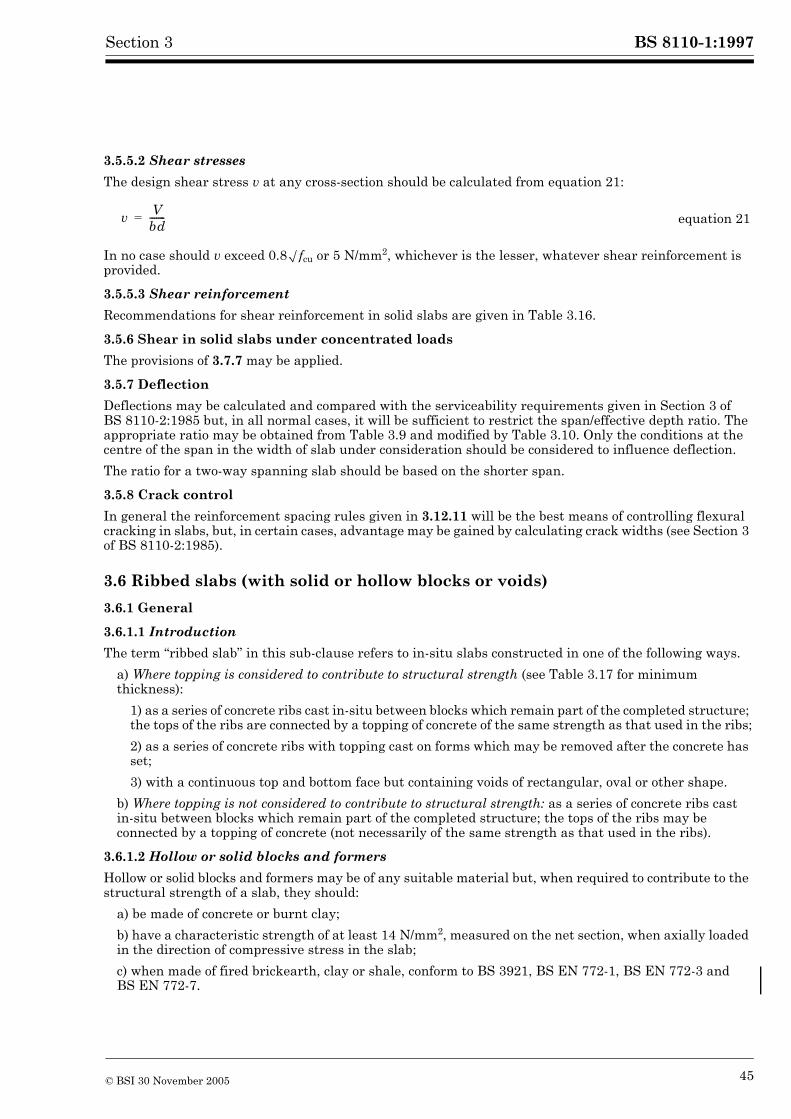
3.5.5.2 Shear stresses
The design shear stress v at any cross-section should be calculated from equation 21:
In no case should v exceed 0.8Æfcu or 5 N/mm2, whichever is the lesser, whatever shear reinforcement is provided.
3.5.5.3 Shear reinforcement
Recommendations for shear reinforcement in solid slabs are given in Table 3.16.
3.5.6 Shear in solid slabs under concentrated loads
The provisions of 3.7.7 may be applied.
3.5.7 Deflection
Deflections may be calculated and compared with the serviceability requirements given in Section 3 of BS 8110-2:1985 but, in all normal cases, it will be sufficient to restrict the span/effective depth ratio. The appropriate ratio may be obtained from Table 3.9 and modified by Table 3.10. Only the conditions at the centre of the span in the width of slab under consideration should be considered to influence deflection.
The ratio for a two-way spanning slab should be based on the shorter span.
3.5.8 Crack control
In general the reinforcement spacing rules given in 3.12.11 will be the best means of controlling flexural cracking in slabs, but, in certain cases, advantage may be gained by calculating crack widths (see Section 3 of BS 8110-2:1985).
3.6 Ribbed slabs (with solid or hollow blocks or voids)
3.6.1 General
3.6.1.1 Introduction
The term “ribbed slab” in this sub-clause refers to in-situ slabs constructed in one of the following ways.
a) Where topping is considered to contribute to structural strength (see Table 3.17 for minimum thickness):
1) as a series of concrete ribs cast in-situ between blocks which remain part of the completed structure; the tops of the ribs are connected by a topping of concrete of the same strength as that used in the ribs;
2) as a series of concrete ribs with topping cast on forms which may be removed after the concrete has set;
3) with a continuous top and bottom face but containing voids of rectangular, oval or other shape.
b) Where topping is not considered to contribute to structural strength: as a series of concrete ribs cast in-situ between blocks which remain part of the completed structure; the tops of the ribs may be connected by a topping of concrete (not necessarily of the same strength as that used in the ribs).
3.6.1.2 Hollow or solid blocks and formers
Hollow or solid blocks and formers may be of any suitable material but, when required to contribute to the structural strength of a slab, they should:
a) be made of concrete or burnt clay;
b) have a characteristic strength of at least 14 N/mm2, measured on the net section, when axially loaded in the direction of compressive stress in the slab;
c) when made of fired brickearth, clay or shale, conform to BS 3921, BS EN 772-1, BS EN 772-3 and BS EN 772-7.
equation 21v Vbd-------=
BS 8110-1:1997
46 © BSI 30 November 2005
Section 3
3.6.1.3 Spacing and size of ribs
In-situ ribs should be spaced at centres not exceeding 1.5 m and their depth, excluding any topping, should not exceed four times their width. The minimum width of rib will be determined by considerations of cover, bar spacing and fire.
3.6.1.4 Non-structural side support
Where the side of a slab is built into a wall or rests on a beam parallel to the ribs, that side should be strengthened by the formation of a rib of width equal to that of the bearing.
3.6.1.5 Thickness of topping used to contribute to structural strength
The thickness after any necessary allowance has been made for wear, should be not less than those of Table 3.17.
3.6.1.6 Hollow block slabs where topping is not used to contribute to structural strength
When a slab is constructed to b) of Table 3.17 the blocks should conform to 3.6.1.2. In addition the thickness of the block material above its void should be not less than 20 mm nor less than one-tenth of the dimension of the void measured transversely to the ribs. The overall thickness of the block and topping (if any) should be not less than one-fifth of the distance between ribs.
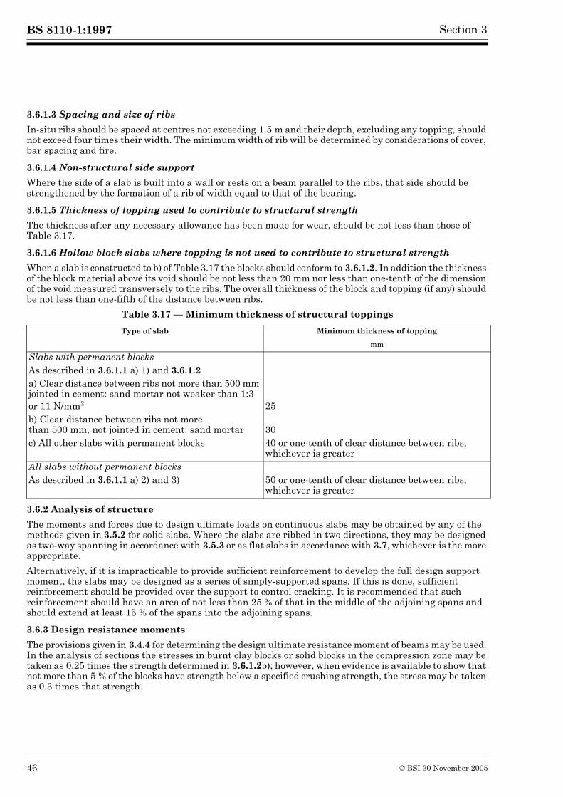
Table 3.17 — Minimum thickness of structural toppings
3.6.2 Analysis of structure
The moments and forces due to design ultimate loads on continuous slabs may be obtained by any of the methods given in 3.5.2 for solid slabs. Where the slabs are ribbed in two directions, they may be designed as two-way spanning in accordance with 3.5.3 or as flat slabs in accordance with 3.7, whichever is the more appropriate.
Alternatively, if it is impracticable to provide sufficient reinforcement to develop the full design support moment, the slabs may be designed as a series of simply-supported spans. If this is done, sufficient reinforcement should be provided over the support to control cracking. It is recommended that such reinforcement should have an area of not less than 25 % of that in the middle of the adjoining spans and should extend at least 15 % of the spans into the adjoining spans.
3.6.3 Design resistance moments
The provisions given in 3.4.4 for determining the design ultimate resistance moment of beams may be used. In the analysis of sections the stresses in burnt clay blocks or solid blocks in the compression zone may be taken as 0.25 times the strength determined in 3.6.1.2b); however, when evidence is available to show that not more than 5 % of the blocks have strength below a specified crushing strength, the stress may be taken as 0.3 times that strength.
Type of slab Minimum thickness of topping
mm
Slabs with permanent blocksAs described in 3.6.1.1 a) 1) and 3.6.1.2a) Clear distance between ribs not more than 500 mm jointed in cement: sand mortar not weaker than 1:3 or 11 N/mm2 25b) Clear distance between ribs not more than 500 mm, not jointed in cement: sand mortar 30c) All other slabs with permanent blocks 40 or one-tenth of clear distance between ribs,
whichever is greaterAll slabs without permanent blocksAs described in 3.6.1.1 a) 2) and 3) 50 or one-tenth of clear distance between ribs,
whichever is greater
BS 8110-1:1997
© BSI 30 November 2005 47
Section 3
3.6.4 Shear
3.6.4.1 Flat slab construction
If the design assumes this method 3.7.6 should be used. Where a perimeter (see 1.3.3.1) cuts any ribs, they should each be designed to resist an equal proportion of the applied effective design shear force. Shear links in the ribs should continue for a distance of at least d into the solid area.
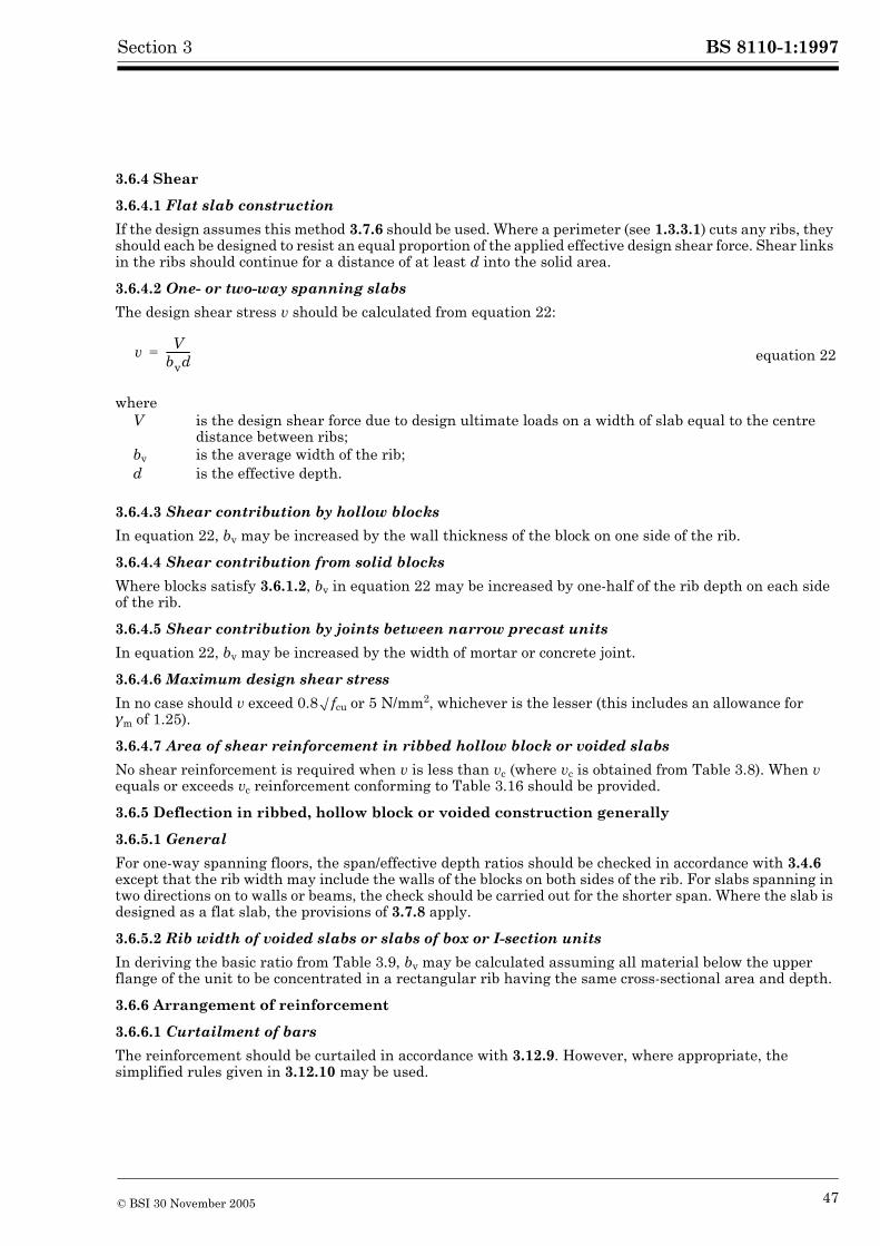
3.6.4.2 One- or two-way spanning slabs
The design shear stress v should be calculated from equation 22:
3.6.4.3 Shear contribution by hollow blocks
In equation 22, bv may be increased by the wall thickness of the block on one side of the rib.
3.6.4.4 Shear contribution from solid blocks
Where blocks satisfy 3.6.1.2, bv in equation 22 may be increased by one-half of the rib depth on each side of the rib.
3.6.4.5 Shear contribution by joints between narrow precast units
In equation 22, bv may be increased by the width of mortar or concrete joint.
3.6.4.6 Maximum design shear stress
In no case should v exceed 0.8Æfcu or 5 N/mm2, whichever is the lesser (this includes an allowance for ¾m of 1.25).
3.6.4.7 Area of shear reinforcement in ribbed hollow block or voided slabs
No shear reinforcement is required when v is less than vc (where vc is obtained from Table 3.8). When v equals or exceeds vc reinforcement conforming to Table 3.16 should be provided.
3.6.5 Deflection in ribbed, hollow block or voided construction generally
3.6.5.1 General
For one-way spanning floors, the span/effective depth ratios should be checked in accordance with 3.4.6 except that the rib width may include the walls of the blocks on both sides of the rib. For slabs spanning in two directions on to walls or beams, the check should be carried out for the shorter span. Where the slab is designed as a flat slab, the provisions of 3.7.8 apply.
3.6.5.2 Rib width of voided slabs or slabs of box or I-section units
In deriving the basic ratio from Table 3.9, bv may be calculated assuming all material below the upper flange of the unit to be concentrated in a rectangular rib having the same cross-sectional area and depth.
3.6.6 Arrangement of reinforcement
3.6.6.1 Curtailment of bars
The reinforcement should be curtailed in accordance with 3.12.9. However, where appropriate, the simplified rules given in 3.12.10 may be used.
equation 22
whereV is the design shear force due to design ultimate loads on a width of slab equal to the centre
distance between ribs;bv is the average width of the rib;d is the effective depth.
v Vbvd----------=
BS 8110-1:1997
48 © BSI 30 November 2005
Section 3
3.6.6.2 Reinforcement in topping for ribbed or hollow block slabs
Consideration should be given to providing a single layer of welded steel fabric, having a cross-sectional area of not less than 0.12 % of the topping, in each direction; the spacing between wires should not be greater than half the centre-to-centre distance between ribs.
3.6.6.3 Links in ribs
Provided the geometry satisfies 3.6.1.3 ribs reinforced with a single bar or ribs in waffle slabs do not require links unless shear or fire resistance requirements so dictate. However consideration should be given to the use of purpose made spacers occupying the full width of the rib to ensure correct cover to the bar.
Where two or more bars are used in a rib, the use of link reinforcement in addition to normal spacers is recommended except in waffle slabs, to ensure correct cover to reinforcement. The spacing of the links can generally be of the order of 1 m to 1.5 m depending on the size of the main bars
The cover of the link reinforcement should satisfy the durability requirement of Table 3.4 but need not satisfy the requirements for fire resistance in Table 3.5 provided the cover to the main bars does so.
3.7 Flat slabsNOTE See 1.3.2 for definitions specific to flat slabs.
3.7.1 General
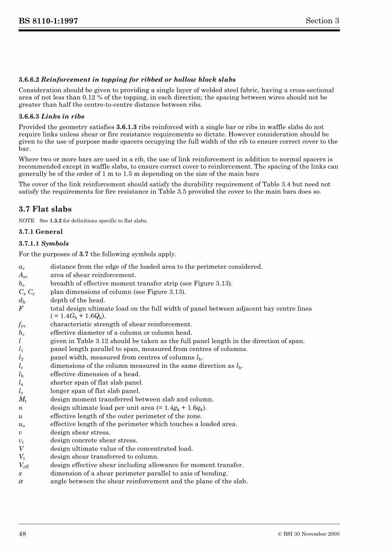
3.7.1.1 Symbols
For the purposes of 3.7 the following symbols apply.
av distance from the edge of the loaded area to the perimeter considered.Asv area of shear reinforcement.be breadth of effective moment transfer strip (see Figure 3.13).Cx Cy plan dimensions of column (see Figure 3.13).dh depth of the head.F total design ultimate load on the full width of panel between adjacent bay centre lines
( = 1.4Gk + 1.6Qk).fyv characteristic strength of shear reinforcement.hc effective diameter of a column or column head.l given in Table 3.12 should be taken as the full panel length in the direction of span.l1 panel length parallel to span, measured from centres of columns.l2 panel width, measured from centres of columns lh.lc dimensions of the column measured in the same direction as lh.lh effective dimension of a head.lx shorter span of flat slab panel.ly longer span of flat slab panel.Mt design moment transferred between slab and column.n design ultimate load per unit area (= 1.4gk + 1.6qk).u effective length of the outer perimeter of the zone.uo effective length of the perimeter which touches a loaded area.v design shear stress.vc design concrete shear stress.V design ultimate value of the concentrated load.Vt design shear transferred to column.Veff design effective shear including allowance for moment transfer.x dimension of a shear perimeter parallel to axis of bending.µ angle between the shear reinforcement and the plane of the slab.