bs en746!3!1997 industrial thermoprocessing equipment
DESCRIPTION
ThermalTRANSCRIPT

|||||||||||||||||||||||||||||||||||||||||||||||||||||||||||||||||||||||||||||||||||||||||||||||||||||||||||||||||||||||||||||||||
BRITISH STANDARD BS EN746-3 : 1997
The European Standard EN 746-3 : 1997 has the status of aBritish Standard
ICS 25.180.01
NO COPYING WITHOUT BSI PERMISSION EXCEPT AS PERMITTED BY COPYRIGHT LAW
Industrialthermoprocessingequipment
Part 3. Safety requirements for thegeneration and use of atmosphere gases

BS EN 746-3 : 1997
This British Standard, havingbeen prepared under thedirection of the EngineeringSector Board, was publishedunder the authority of theStandards Board and comes intoeffect on15 September 1997
BSI 1997
The following BSI referencesrelate to the work on thisstandard:Committee reference MCE/3/8Draft for comment 92/76831 DC
ISBN 0 580 28103 5
Amendments issued since publication
Amd. No. Date Text affected
Committees responsible for thisBritish Standard
The preparation of this British Standard was entrusted by Technical CommitteeMCE/3, Safeguarding of machinery, to Subcommittee MCE/3/8, Thermoprocessingequipment Ð Safety, upon which the following bodies were represented:
British Combustion Equipment Manufacturers' Association
British Gas
British Industrial Furnace Constructors' Association
British National Committee for Electroheat
British Non-Ferrous Metals Federation
British Vermiculite Association
Health and Safety Executive
Institute of Materials
Institution of Gas Engineers

BSI 1997 i
BS EN 746-3 : 1997
1) In preparation.
National foreword
This Part of BS EN 746 has been prepared by Subcommittee MCE/3/8 and is theEnglish language version of EN 746-3 : 1997 Industrial thermoprocessingequipment Ð Part 3 : Safety requirements for the generation and use of atmospheregases published by the European Committee for Standardization (CEN).
EN 746-3 was produced as a result of international discussions in which the UnitedKingdom took an active part.
Cross-references
Publication referred to Corresponding British Standard
EN 88 BS EN 88 : 1991 Pressure governors for gas appliances forinlet pressures up to 200 mbar
EN 161 BS EN 161 : 1991 Automatic shut-off valves for gas burnersand gas appliancesBS EN 292 Safety of machinery. Basic concepts, generalprinciples for design
EN 292-1 : 1991 BS EN 292-1 : 1991 Basic terminology, methodology
EN 292-2 : 1991 BS EN 292-2 : 1991 Technical principles and specifications
EN 298 BS EN 298 : 1994 Automatic gas burner control systems forgas burners and gas burning appliances with or withoutfansBS EN 746 Industrial thermoprocessing equipment
EN 746-1 1) BS EN 746-1 : 1997 Common safety requirements forindustrial thermoprocessing equipment
EN 746-2 BS EN 746-2 : 1997 Safety requirements for combustion andfuel handling systemsBS EN 60204 Safety of machineryElectrical equipment of machines
EN 60204-1 BS EN 60204-1 : 1993 Specification for general requirementsBS EN 60519 Safety in electroheat installations
EN 60519-1 BS EN 60519-1 : 1993 General requirements
EN 60519-2 BS EN 60519-2 : 1994 Particular requirements for resistanceheating equipment
EN 60519-3(IEC 519-3)
BS EN 60519-3 : 1996 Particular requirements for inductionand conduction heating and induction melting installations
Compliance with a British Standard does not of itself confer immunityfrom legal obligations.
Summary of pages
This document comprises a front cover, an inside front cover, pages i and ii, the ENtitle page, pages 2 to 28, an inside back cover and a back cover.

ii blank

www.bzfxw.com
CENEuropean Committee for Standardization
Comite EuropeÂen de Normalisation
EuropaÈisches Komitee fuÈ r Normung
Central Secretariat: rue de Stassart 36, B-1050 Brussels
1997 All rights of reproduction and communication in any form and by any means reserved to CEN and itsmembers.
Ref. No. EN 746-3 : 1997 E
EUROPEAN STANDARD EN 746-3
NORME EUROPEÂ ENNE
EUROPAÈ ISCHE NORM March 1997
ICS 25.180.01
Descriptors: Industrial products, heating installation, heat treatment, dangerous machines, safety of machinery, accident prevention,hazards, controlled atmospheres, gases, safety devices, specifications
English version
Industrial thermoprocessing equipment Ð Part 3 : Safetyrequirements for the generation and use of atmosphere gases
Equipements thermiques industriels ÐPartie 3 : Prescriptions de seÂcurite pour lageÂneÂration et l'utilisation des gaz d'atmospheÁre
Industrielle Thermoprozebanlagen ÐTeil 3 : Sicherheitsanforderungen fuÈr die Erzeugungund Anwendung von Schutz-und Reaktionsgasen
This European Standard was approved by CEN on 1997-02-15. CEN members arebound to comply with the CEN/CENELEC Internal Regulations which stipulate theconditions for giving this European Standard the status of a national standardwithout any alteration.
Up-to-date lists and bibliographical references concerning such national standardsmay be obtained on application to the Central Secretariat or to any CEN member.
This European Standard exists in three official versions (English, French, German).A version in any other language made by translation under the responsibility of aCEN member into its own language and notified to the Central Secretariat has thesame status as the official versions.
CEN members are the national standards bodies of Austria, Belgium, Denmark,Finland, France, Germany, Greece, Iceland, Ireland, Italy, Luxembourg, Netherlands,Norway, Portugal, Spain, Sweden, Switzerland and United Kingdom.
www.bzfxw.com
Page 2EN 746-3 : 1997
BSI 1997
Foreword
This European Standard has been prepared byTechnical Committee CEN/TC 186, Industrialthermoprocessing Ð Safety, the secretariat of which isheld by DIN.
This European Standard shall be given the status of anational standard, either by publication of an identicaltext or by endorsement, at the latest by September1997, and conflicting national standards shall bewithdrawn at the latest by September 1997.
The working group that drafted this part of EN 746comprised experts from the following countries:France, Germany, Italy, Switzerland and the UnitedKingdom.
This standard forms one part of safety standardscovering industrial thermoprocessing equipment.
The full list of Parts of this standard is given below:
EN746 Industrial thermoprocessing equipment
Part 1: Common safety requirements forindustrial thermoprocessing equipment;
Part 2: Safety requirements for combustionand fuel handling systems;
Part 3: Safety requirements for thegeneration and use of atmosphere gases;
Part 4: Particular safety requirements forhot dip galvanising thermoprocessingequipment;
Part 5: Particular safety requirements forsalt bath thermoprocessing equipment;
Part 6: Particular safety requirements forliquid phase treatment thermoprocessingequipment;
Part 7: Particular safety requirements forvacuum thermoprocessing equipment;
Part 8: Particular safety requirements forquenching equipment.
This European Standard has been prepared under amandate given to CEN by the European Commissionand the European Free Trade Association, andsupports essential requirements of EU Directive(s).
For relationship with EU Directive(s), see informativeannex ZA, which is an integral part of this standard.
An assessment of the foreseeable risks arising from theuse of the equipment was carried out when thisstandard was prepared.
Contents
Page
Foreword 2
Introduction 3
1 Scope 3
2 Normative references 3
3 Definitions 4
4 List of hazards 6
5 Safety requirements for the use ofatmosphere gases 12
5.1 Purging 12
5.2 Safety control equipment foratmosphere gases 13
5.3 Thermoprocessing equipmentrequirements 14
6 Safety requirements for atmospheregas generators 16
6.1 Reaction gas supplies 16
6.2 Fuel gas supplies 16
6.3 Air supplies 16
6.4 Mixture supplies 17
6.5 Electrical supplies 17
6.6 Cooling water supplies and discharge 17
6.7 Atmosphere gas supplies anddistribution 17
6.8 System requirements 17
7 Verification of the safety requirementsand/or measures 19
8 Information for use 19
8.1 Instruction handbook 19
8.2 Marking 20
Annexes
A (informative) Typical atmospheregases 21
B (informative) Explosion hazards of gasmixtures containing combustibles 22
C (informative) Inert gas purging 23
D (informative) Bibliography 24
E (informative) Used definitions 25
ZA (informative) Clauses of this EuropeanStandard addressing essentialrequirements or other provisions ofEU Directives. 28

www.bzfxw.com
Page 3EN 746-3 : 1997
BSI 1997
IntroductionThis standard has been prepared to be a harmonizedstandard to provide one means of conforming with theessential requirements of the Machinery Directive andassociated EFTA Regulations.
The extent to which hazards are covered is indicatedin the scope of this standard. In addition, machineryshall comply as appropriate with EN 292 for hazardswhich are not covered by this standard.
This European Standard is a type C-standard asdefined in EN 292.
The equipment dealt with and the extent to whichhazards are covered are indicated in the scope of thisPart of EN 746.
Where for clarity an example of a preventativemeasure is given in the text, this should not beconsidered as the only possible solution. Anyother solution leading to the same riskreduction is permissible if an equivalent levelof safety is achieved.
This Part of EN 746 assumes that the installations areoperated and maintained by trained personnel.
1 ScopeThis Part of EN 746 specifies safety requirements foratmosphere gas systems and their use in industrialthermoprocessing equipment and associated plant,including systems for the production of atmospheregases by reaction inside the thermoprocessingequipment.
It applies to the supply of atmosphere gases, gaseousand liquid additions to, and their removal fromindustrial thermoprocessing equipment and associatedplant, confined to equipment integrated in thethermoprocessing and associated plant.
This Part of EN 746 also details the anticipatedsignificant hazards associated with atmosphere gassystems and their use in industrial thermoprocessingequipment and specifies the appropriate preventativemeasures for the reduction or elimination of thesehazards.
This Part of EN 746 does not apply to atmosphereprocess gases, essential safety equipment, start-up,operation and shut-down of thermoprocessing plant forsemi-conductor devices for which special additionalengineering requirements are necessary.
This Part of EN 746 specifies the requirements to bemet to ensure the safety of persons and propertyduring commissioning, start up, operation, shut downand maintenance, as well as in the event of foreseeablefaults or malfunctions which can occur in theequipment. It specifies the safety requirements atstages in the life of the equipment, and its design,ordering, construction and use.
This Part of EN 746 applies to equipment which isplaced on the market after the date of issue of thisstandard.
The hazards covered by this Part of EN 746 are listedin clause 4.
A table of typical atmosphere gases is given inannex A.
2 Normative referencesThis European Standard incorporates by dated orundated reference, provisions from other publications.These normative references are cited at theappropriate places in the text and the publications arelisted hereafter. For dated references, subsequentamendments to or revisions of any of thesepublications apply to this European Standard onlywhen incorporated in it by amendment or revision. Forundated references the latest edition of the publicationreferred to applies.
EN 88 Pressure governors for gasappliances for inlet pressures up to200 mbar;
EN 161 Automatic shut-off valves for gasburners and gas appliances;
EN 292-1:1991 Safety of machinery Ð Basicconcepts, general principles fordesign Ð Part 1: Basicterminology, methodology;
EN 292-2:1991 Safety of machinery Ð Basicconcepts, general principles fordesign Ð Part 2: Technicalprinciples and specifications;
EN 298 Automatic gas burner controlsystems for gas burners and gasburning appliances with orwithout fans;
EN 746-1 Industrial thermoprocessingequipment Ð Part 1: Commonsafety requirements for industrialthermoprocessing equipment;
EN 746-2 Industrial thermoprocessingequipment Ð Part 2: Safetyrequirements for combustion andfuel handling systems;
EN 60204-1 Safety of machinery Ð Electricalequipment of machines Ð Part 1:General requirements(IEC 204-1:1992, modified);
EN 60519-1 Safety in electroheatinstallations Ð Part 1: Generalrequirements;
EN 60519-2 Safety in electroheatinstallations Ð Part 2: Particularrequirements for resistance heatingequipment;

www.bzfxw.com
Page 4EN 746-3 : 1997
BSI 1997
IEC 364-4-41 Electrical installations of buildingsPart 4: Protection for safetyChapter 41: Protection againstelectrical shock;
IEC 364-4-43 Electrical installations of buildingsPart 4: Protection for safetyChapter 43: Protection againstovercurrent;
IEC 364-4-47 Electrical installations of buildingsPart 4: Protection for safetyChapter 47: Application ofprotective measures for safetySection 470 Ð GeneralSection 471 Ð Measures ofprotection against electric shock;
IEC 364-4-442 Electrical installations of buildingsPart 4: Protection for safetyChapter 44: Protection againstovervoltagesSection 442: Protection oflow-voltage installations againstfaults between high-voltage systemsand earth
IEC 364-4-443 Electrical installations of buildingsPart 4: Protection for safetyChapter 44; Protection againstovervoltagesSection 443 Ð Protection againstovervoltages of atmospheric originor due to switching;
IEC 364-4-473 Electrical installations of buildingsPart 4: Protection for safetyChapter 47: Application ofprotective measures for safetySection 473 Ð Measures ofprotection against overcurrent;
IEC 364-4-45 Electrical installations of buildingsPart 4: Protection for safetyChapter 45: Protection againstundervoltage;
IEC 364-4-46 Electrical installations of buildingsPart 4: Protection for safetyChapter 46: Isolation andswitching;
IEC 519-3 Safety in electroheatinstallations Ð Part 3: Particularrequirements for induction andconduction heating and inductionmelting installations.
3 DefinitionsFor the purposes of this standard the followingdefinitions apply:
NOTE. An alphabetic listing of the definitions, as well as theircross-references in German, French and English is given ininformative annex E.
3.1 industrial thermoprocessing and associatedequipment
Any equipment through or into which the atmospheregases flow.
NOTE. This includes atmosphere gas distribution systems, safetycontrol equipment and the furnace or other enclosures in whichatmosphere gases are used.
3.2 safe ignition temperature
The minimum temperature at which spontaneous, safeauto-ignition of flammable gases occurs.
NOTE. The safe ignition temperature has been establishedat 750 ÊC.
3.3 purging
The general displacement of one type of atmospherewithin a thermal processing plant by another.
3.4 flammable atmosphere gas
Any gas mixture that is capable of forming flammablemixtures with air or oxygen under the conditions oftemperature and pressure used in the process.
NOTE 1. Typically any gas mixture containing more than 5 % (V/V)combustibles (H2+CO +CH4) of which CH4 is not more than 1 %(V/V), where the remainder of the mixture is non-flammable, isconsidered to be flammable. Any gas mixture which contains morethan 1 % (V/V) CnHm or 2,5 % (V/V) NH3 where the remainder ofthe mixture is non-flammable is also considered to be flammable(see annexes A and B).
NOTE 2. A flammable gas which contains 1 % (V/V) or less oxygencannot in itself form an explosive or flammable mixture.
3.5 non-flammable atmosphere gas
Any gas mixture which is not capable of formingflammable mixtures with air or oxygen under theconditions of temperature and pressure used in theprocess.
NOTE. Typically any gas mixture containing 5 % (V/V) or less ofcombustibles (H2+CO +CH4) of which CH4 is not more than 1 % ofthe 5 % (V/V) and the remainder is non-flammable and which willnot support combustion.
3.6 inert gas
A non-flammable gas which will not supportcombustion and does not react to produce aflammable gas.
NOTE 1. An inert gas can safely be used for pre- and post-purgingof cold and hot enclosures of thermoprocessing equipment.
NOTE 2. Inert gas can be produced by appropriate adjustment ofan exothermic generator. In the event of malfunction such a gascan be flammable and provisions should be taken to ensure thatthe adjustment is correct.
3.7 toxic atmosphere gas
A gas which, in addition to having asphyxiatingproperties, also acts as a poison.

www.bzfxw.com
Page 5EN 746-3 : 1997
BSI 1997
3.8 fluid
A liquid or a gas.
NOTE. If specific reference is made to `liquid' or `gas' this meansthe physical state of the fluid being considered.
3.9 safe level of vacuum
The absolute pressure of an evacuated furnacechamber/enclosure corresponding to safe atmosphereconditions.
NOTE. The safe level of vacuum has been established as amaximum of 45 mbar absolute (1 bar = 105 Pa).
3.10 safety purge volume
The volume of inert purge gas needed to displaceeither air or a flammable gas from a furnacechamber/enclosure to achieve 1 % (V/V) or less oxygenand/or a non-flammable atmosphere gas (as definedin 3.5) and/or 25 % of the lower flammability limit.
NOTE. Typically this will be a volume equal to five times thevolume of the thermoprocessing equipment chamber to be purged,see annex C.
3.11 atmosphere gas generating system
Equipment that converts or modifies a mixture offluids (gaseous or liquid) into a gas which can beutilized as the controlled atmosphere within thethermoprocessing equipment.
3.12 automatic re-start
Automatic repetition of the starting up sequencewithout manual intervention.
3.13 flame instability
Undesirable variation in the size, shape and position ofa flame.
3.14 flame sensor
That part of a flame safeguard or flame monitoringsystem that is responsive to flame properties andwhich signals the presence of flame.
3.15 sensor output drift
A condition occurring within the flame sensor wherebyit responds to flame characteristics outside the safetyrange for which it was designed.
3.16 flame failure
Loss of flame from the normally detected position byany cause other than the action of de-energizing thesafety shut-off valves system [EN 746-2].
3.17 flame safeguard
A device responsive to flame properties, detecting thepresence of a nominated flame and, in the event ofignition failure or subsequent flame failure, causingsafety shut-down or lock out.
It consists of a flame sensor, an amplifier and a relayfor signal transmission. These parts, with the possibleexception of the actual flame sensor, may beassembled in a single housing for use in conjunctionwith a programming unit [EN 746-2].
3.18 flame trap
A device capable of arresting a flame while allowingthe passage of gas.
3.19 start-up interlock
The safety shut-down condition of the control systemsuch that re-start cannot be accomplished withoutmanual re-set.
3.20 multiturn valve
A valve which, in order to operate from the fullyclosed to the fully open position, requires a number ofrevolutions of the operating key or handwheel to becompleted.
3.21 non-return valve
A device to prevent the reversal of flow of air, fuel,oxygen etc. [EN 746-2].
3.22 pilot flame
Pilot burner flame that is used to ignite the main flame[EN 746-2].
3.23 interrupted pilot
A pilot which is ignited each time the burner is startedup and which is extinguished at the end of the mainflame establishment period.
3.24 pilot shrinkage
Unintended reduction in the length of the pilot flame.
3.25 safe start check
A means of providing safety shut-down or start-upinterlock on start-up if a fault or flame simulatingcondition is present.
3.26 safe shut-down
The shutting off of all reaction gas and reaction airsupplies to the atmosphere generator.
NOTE 1. This can be accomplished either manually orautomatically.
NOTE 2. This should not be confused with system of safetyshut-down (see 3.27).
3.27 system of safety shut-down
A system that provides the automatic shutting off of allgas and ignition energy.
3.28 safety shut-off valve system
A system of valves with associated circuits whichenables the supply of gas to be admitted or shut off.
3.29 slam shut valve
A valve which automatically closes when it is actuatedby an increase in the downstream line pressure abovea set limit. Manual intervention is required to re-openthe valve.
3.30 start gas flame
A flame established at the start gas rate either at themain burner or at a separate pilot burner.

www.bzfxw.com
Page 6EN 746-3 : 1997
BSI 1997
Table 1. List of hazards, hazardous situations and preventative measures
1 3 2 4 5 6
Clause Hazards ReferenceEN 292-1 :1991
Hazardous situation Preventative measures Reference
1 MECHANICAL
1.1 General 4.2 EN 746-1
2 ELECTRICAL
2.1 General 4.3
2.2 Thermal radiation andother phenomena
* Breakdown/reduction of electricalinsulation* Cable damage/Shortcircuits:
± Fire± Electric shock
* System design* Correct placement ofcables* Protection of cables* Fire fighting equipment(suitable for electricalsystems)
EN 746-15.3.2.186.5
2.3 External influences onelectrical equipment
* Corruption of controlcircuits, particularlysoftware systems* Failure of safetycontrol:
± Fire/Explosion± Toxicity/Asphyxiation
* System design* Protection of hardware* Monitoring systems* First aid:
± equipment± training
* Fire fighting equipment
EN 746-15.3.2.186.5
3 THERMAL
3.1 General 4.4
Flames, Explosions,Radiation
* Personal injuries suchas:
± Flash/radiation,burns± Dehydration± Eyesight damage
* Deterioration of jointsand pipework and/ordistortion of structures:
± Escaping offlammable or toxicfluids (gases/liquids)
* Ejection of parts
* System design*Monitoring/inspection/maintenance* Operator:
± Instruction± Training
* Personal protectionequipment*First aid:
± Equipment± Training
* Safety devices in theworkshop* Fire fighting equipment
EN 746-1EN 746-2568.1
4 List of hazards
The anticipated significant hazards are detailed intable 1. For ease of reference this table also indicatesthe hazardous situations and correspondingpreventative measures and should be used inconjunction with Parts 1 and 2 of EN 746 and clauses 5,6 and 8 of this part of EN 746, as identified in thereference column.

Page 7EN 746-3 : 1997
BSI 1997
Table 1. List of hazards, hazardous situations and preventative measures (continued)
1 3 2 4 5 6
Clause Hazards ReferenceEN 292-1 :1991
Hazardous situation Preventative measures Reference
4 HAZARDS GENERATED BY MATERIALS AND SUBSTANCES PROCESSED/USED/EXHAUSTED
4.1 General 4.8
4.2 * Contact with harmfulliquids
* Contact with orinhalation of harmfulgases/vapours/fumes
* Personal injuries suchas:
± Skin effects± Poisoning± Physiological effects± Respiratory/asphyxiating effects
* Regulations for storage/use/disposal* System design*Monitoring/inspection/maintenance* Personal protectionequipment* First aid:
± Equipment± Training*Consider:± Permit-to-worksystem± Gas analysingsystem
EN 746-15.3.15.3.2.15.3.2.25.3.2.135.3.2.146.7.36.8.98.1
4.3 Contact with orinhalation of dusts
* Personal injuries suchas:
± Skin effects± Respiratory effects± Poisoning± Carcinogenic effectsfrom nickel- bearingdusts
* Regulations for storage/use/disposal *Procedures forassembling, maintenanceand dismantling* Provisions for disposal
8.1.68.1.7
5 FIRE AND EXPLOSION
5.1 General 4.8
5.2 Fire hazard * Property damageand/or personal injurycaused by flammablefluids (gases/liquids)
* System:± Design± Safety systems
* Fire fighting equipment* Monitoring/inspection/maintenance* Operator:
± Instruction± Training
* Plant housekeepingprocedures* First aid:
± Equipment± Training
EN 746-1EN 746-25.36.88.1
5.3 Explosion hazard * Property damage and/orpersonal injury causedby flammable fluids(gases/liquids)
* System± Design± Safety system
* Fire fighting equipment*Monitoring/inspection/maintenance* Operator:
± Instruction± Training
* Explosion reliefdevices
568.1
Page 8EN 746-3 : 1997
BSI 1997
Table 1. List of hazards, hazardous situations and preventative measures (continued)
1 3 2 4 5 6
Clause Hazards ReferenceEN 292-1 :1991
Hazardous situation Preventative measures Reference
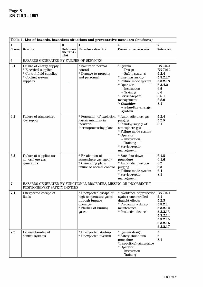
6 HAZARDS GENERATED BY FAILURE OF SERVICES
6.1 Failure of energy supply* Electrical supplies* Control fluid supplies* Cooling systemsupplies
* Failure to normalcontrol* Damage to propertyand personnel
* System:± Design± Safety systems
* Inert gas supply* Failure mode system* Operator:
± Instruction± Training
* Service/repairmanagement* Consider
± Standby energysystem
EN 746-1EN 746-25.2.45.3.2.175.3.2.186.3.4.26.56.66.8.16.8.98.1
6.2 Failure of atmospheregas supply
* Formation of explosiongas/air mixtures inindustrialthermoprocessing plant
* Automatic inert gaspurging* Standby supply ofatmosphere gas* Failure mode system* Operator:
± Instruction± Training
* Service/repairmanagement
5.2.45.2.58.1
6.3 Failure of supplies foratmosphere gasgenerators
* Breakdown ofatmosphere gas supply* Generating plant/failure of normal control
* Safe shut-downprocedure* Automatic inert gaspurging* Failure mode system* Service/repairmanagement
6.1.56.1.66.26.36.48.1
7 HAZARDS GENERATED BY FUNCTIONAL DISORDERS, MISSING OR INCORRECTLYPOSITIONED/SET SAFETY DEVICES
7.1 Unexpected escape offluids
* Unexpected escape ofhigh temperature gasesthrough furnaceopenings* Flashes of burninggases
* Avoidance of/protectionagainst uncontrolleddraught effects* Precautions duringmaintenance* Protective devices
EN 746-15.15.2.35.3.2.15.3.2.125.3.2.135.3.2.145.3.2.155.3.2.165.3.2.17
7.2 Failure/disorder ofcontrol systems
* Unexpected start-up* Unexpected overrun
* System design* Safety shut-downprocedure*Inspection/maintenance* Operator:
± Instruction± Training
568.1

Page 9EN 746-3 : 1997
BSI 1997
Table 1. List of hazards, hazardous situations and preventative measures (continued)
1 3 2 4 5 6
Clause Hazards ReferenceEN 292-1 :1991
Hazardous situation Preventative measures Reference
7.3 Errors of fitting * Damage to propertyand/or personal injuries
* System design*Marking/identification ofcomponents* Supplier information/components* Spare partsmaintenancemanagement* Instruction formaintenance*Consider:
± PERMIT-TO-WORKsystem
568.18.2
7.4 Loading and unloadingmeans for workpiecesbeing processed
* Personal injuries suchas:
± Burns± Poisoning
* Damage to propertycaused by:
± Overheating± Incorrect purging± Fire
* System design* Sequence logic* Personal protection*Inspection/maintenance* Operator:
± Instruction± Training
EN 746-15.15.2.75.3.2.168.1
7.5 * Pressure or flowcontrol devices
* Low or hightemperature detectors
* Incorrect atmospheregas production or use,resulting in:
± Fire/explosion± Poisoning
* System design* Monitor/inspection/maintenance* Operator:
± Instruction± Training
* Explosion reliefdevices*Fire fighting equipment*First aid:
± Equipment± Training
* Consider:± Gas analysingsystem
5.25.2.65.3.2.76.1.16.8
7.6 Explosion reliefs (iffitted)
* Leakage of atmospheregas into the workshop,causing:
± Fire/explosion± Poisoning/asphyxiation
*Inspection/maintenance* General ventilation ofworkshop* Operator:
± Instruction± Training
* Fire fighting equipment* Consider:
± PERMIT-TO-WORKsystem
5.3.2.178.1

Page 10EN 746-3 : 1997
BSI 1997
Table 1. List of hazards, hazardous situations and preventative measures (continued)
1 3 2 4 5 6
Clause Hazards ReferenceEN 292-1 :1991
Hazardous situation Preventative measures Reference
7.7 Flame failure control(main burner(s) andpilot(s))
* Incorrect production oruse of atmosphere gas,resulting in:
± Unreliable ignition/explosion± Risk of personalinjuries (burns)
* System design* Self checking flamesafeguard* Interlocks preventingsequence continuation*Monitoring/inspection/maintenance* Operator:
± Instruction± Training
* Safety shut-downprocedure* First aid:
± Equipment± Training
EN 746-25.1.3.35.3.2.145.3.2.155.3.2.166.8.56.8.66.8.98.1
7.8 Inert purging gassupplies
* Incorrect purge of airor atmosphere gasesfrom thermal processingequipment, resulting in:
± Fire/explosion± Personal injuries(burns)
* System design* Monitor/inspection/maintenance* Operator:
± Instruction± Training
* Operating manual* First aid:
± Equipment± Training
* Consider:± PERMIT-TO-WORKsystem
5.15.2.48.1
7.9 Starting and stoppingdevices:* Electrical circuits* Fluids (gas/air/liquids)
* Inability to operateplant correctly causing:
± Fire/explosion± Asphyxiation
* System design* Start & stop logic*Inspection/maintenance*Operator:
± Instruction± Training
* Operating manual
* Consider:± PERMIT-TO-WORKsystem
5.15.2.48.1
Page 11EN 746-3 : 1997
BSI 1997
Table 1. List of hazards, hazardous situations and preventative measures (continued)
1 3 2 4 5 6
Clause Hazards ReferenceEN 292-1 :1991
Hazardous situation Preventative measures Reference
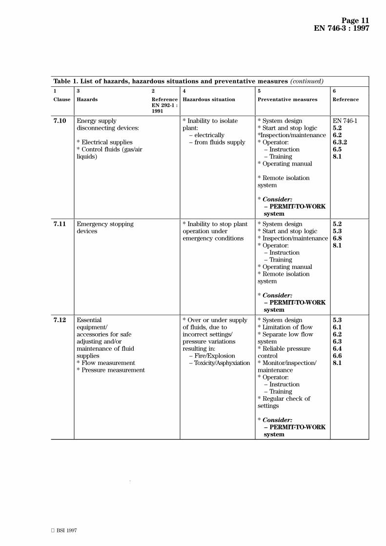
7.10 Energy supplydisconnecting devices:
* Electrical supplies* Control fluids (gas/airliquids)
* Inability to isolateplant:
± electrically± from fluids supply
* System design* Start and stop logic*Inspection/maintenance* Operator:
± Instruction± Training
* Operating manual
* Remote isolationsystem
* Consider:± PERMIT-TO-WORKsystem
EN 746-15.26.26.3.26.58.1
7.11 Emergency stoppingdevices
* Inability to stop plantoperation underemergency conditions
* System design* Start and stop logic* Inspection/maintenance* Operator:
± Instruction± Training
* Operating manual* Remote isolationsystem
* Consider:± PERMIT-TO-WORKsystem
5.25.36.88.1
7.12 Essentialequipment/accessories for safeadjusting and/ormaintenance of fluidsupplies* Flow measurement* Pressure measurement
* Over or under supplyof fluids, due toincorrect settings/pressure variationsresulting in:
± Fire/Explosion± Toxicity/Asphyxiation
* System design* Limitation of flow* Separate low flowsystem* Reliable pressurecontrol* Monitor/inspection/maintenance* Operator:
± Instruction± Training
* Regular check ofsettings
* Consider:± PERMIT-TO-WORKsystem
5.36.16.26.36.46.68.1

Page 12EN 746-3 : 1997
BSI 1997
Table 1. List of hazards, hazardous situations and preventative measures (continued)
1 3 2 4 5 6
Clause Hazards ReferenceEN 292-1 :1991
Hazardous situation Preventative measures Reference
7.13 Equipment evacuatinggases* Natural/forced draught chimneys*Fume extraction ducts* Vents
* Increased toxicity,asphyxiation, fire,explosion if:
± Insufficientevacuation of gases± Flammable deposits,vapours and ignitionsources
NOTE. Effect can be delayedin time
* System design* No interconnection ofvents* Monitoring/inspection/maintenance*Explosion relief devices* Fire fighting equipment
* Consider:
± Gas analysingsystem
5.3.2.135.3.2.145.3.2.155.3.2.166.7.36.8.36.8.48.1
8 HAZARDS GENERATED BY NOISE
8.1 General 4.5 Health damaging effects * System design* Personal protectivedevices
EN 746-1
9 HAZARD COMBINATIONS
General 4.10 Property damage and/orpersonal injuries causedby uncontrolledvoluntary/involuntaryaction
* System design* Failure mode* Safe shut-downprocedures, based onrisk analysis* Monitoring/inspection/maintenance* Regular testing ofsafety systems* Operator:
± Instruction± Training
568.1
5 Safety requirements for the use ofatmosphere gases
5.1 Purging
The following subclauses detail established processrequirements for purging safety controls foratmosphere gas and thermoprocessing equipment thatcan be used in the design of equipment for atmospheregases. These techniques can be applied singly or incombination depending on the application.
5.1.1 General
Specific instructions on the procedure for admittingatmosphere gas into, and removing atmosphere gasfrom, thermoprocessing equipment and enclosuresshall be provided by the manufacturer in accordancewith the purging method(s) adopted (see also annexesA, B and C).
The effects of doors (operational speed andsequencing) and/or other openings on safe purgingshall be taken into account in the selection and use ofpurging procedures.
5.1.2 Purging during start-up
The following purging methods shall be used, eithersingly or in combination.
The normal start-up of thermoprocessing equipment orenclosure which uses a flammable atmosphere gasinvolves replacing the air with the flammableatmosphere gas.
In some cases evacuation or an intermediate purgewith inert gas can be necessary.
5.1.2.1 Purge without ignition
If a flammable atmosphere gas is introduced intoindustrial thermoprocessing equipment or enclosureswhich operate below 750 ÊC, then its introduction shallbe preceded by an inert gas purge to remove air untilthe oxygen content is 1 % (V/V) or less.
NOTE 1. If the atmosphere gas supply source can be adjusted toprovide a non-flammable atmosphere gas, this gas can be utilizedas the purge inert gas.
NOTE 2. The inert gas purge can be omitted provided that the airhas been evacuated to a predetermined safe level of vacuum(see 3.9).
Page 13EN 746-3 : 1997
BSI 1997
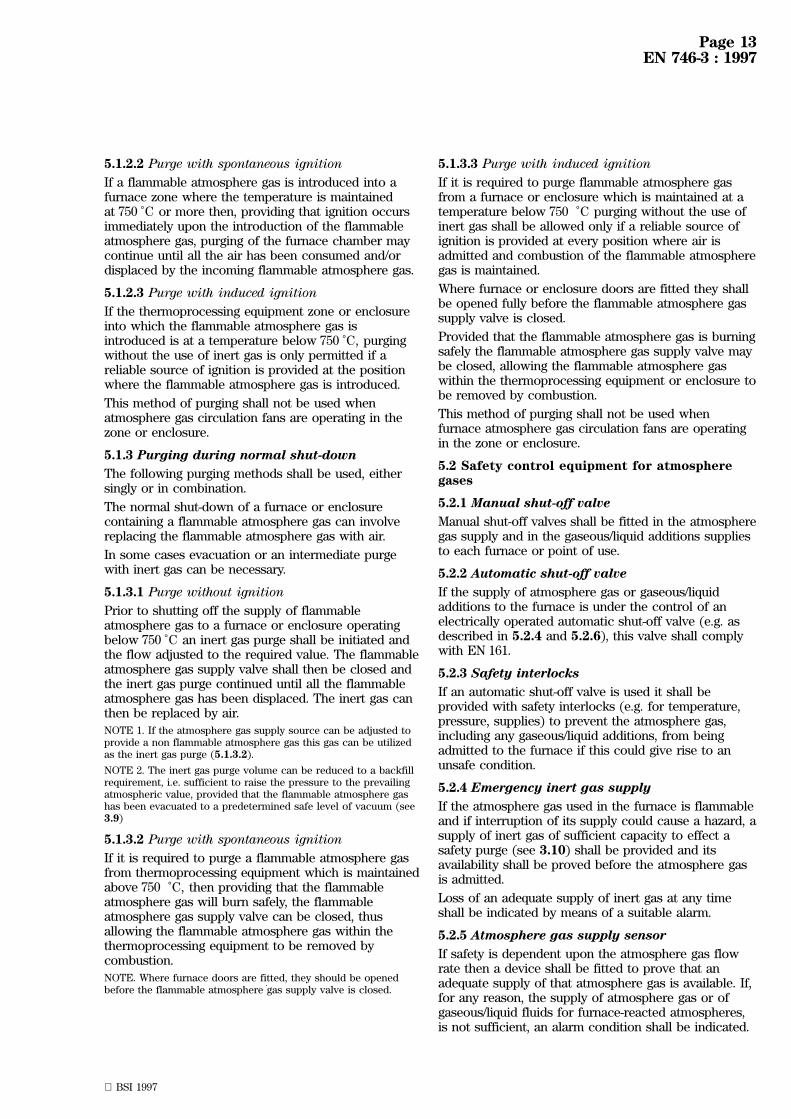
5.1.2.2 Purge with spontaneous ignition
If a flammable atmosphere gas is introduced into afurnace zone where the temperature is maintainedat 750 ÊC or more then, providing that ignition occursimmediately upon the introduction of the flammableatmosphere gas, purging of the furnace chamber maycontinue until all the air has been consumed and/ordisplaced by the incoming flammable atmosphere gas.
5.1.2.3 Purge with induced ignition
If the thermoprocessing equipment zone or enclosureinto which the flammable atmosphere gas isintroduced is at a temperature below 750 ÊC, purgingwithout the use of inert gas is only permitted if areliable source of ignition is provided at the positionwhere the flammable atmosphere gas is introduced.
This method of purging shall not be used whenatmosphere gas circulation fans are operating in thezone or enclosure.
5.1.3 Purging during normal shut-down
The following purging methods shall be used, eithersingly or in combination.
The normal shut-down of a furnace or enclosurecontaining a flammable atmosphere gas can involvereplacing the flammable atmosphere gas with air.
In some cases evacuation or an intermediate purgewith inert gas can be necessary.
5.1.3.1 Purge without ignition
Prior to shutting off the supply of flammableatmosphere gas to a furnace or enclosure operatingbelow 750 ÊC an inert gas purge shall be initiated andthe flow adjusted to the required value. The flammableatmosphere gas supply valve shall then be closed andthe inert gas purge continued until all the flammableatmosphere gas has been displaced. The inert gas canthen be replaced by air.
NOTE 1. If the atmosphere gas supply source can be adjusted toprovide a non flammable atmosphere gas this gas can be utilizedas the inert gas purge (5.1.3.2).
NOTE 2. The inert gas purge volume can be reduced to a backfillrequirement, i.e. sufficient to raise the pressure to the prevailingatmospheric value, provided that the flammable atmosphere gashas been evacuated to a predetermined safe level of vacuum (see3.9)
5.1.3.2 Purge with spontaneous ignition
If it is required to purge a flammable atmosphere gasfrom thermoprocessing equipment which is maintainedabove 750 ÊC, then providing that the flammableatmosphere gas will burn safely, the flammableatmosphere gas supply valve can be closed, thusallowing the flammable atmosphere gas within thethermoprocessing equipment to be removed bycombustion.
NOTE. Where furnace doors are fitted, they should be openedbefore the flammable atmosphere gas supply valve is closed.
5.1.3.3 Purge with induced ignition
If it is required to purge flammable atmosphere gasfrom a furnace or enclosure which is maintained at atemperature below 750 ÊC purging without the use ofinert gas shall be allowed only if a reliable source ofignition is provided at every position where air isadmitted and combustion of the flammable atmospheregas is maintained.
Where furnace or enclosure doors are fitted they shallbe opened fully before the flammable atmosphere gassupply valve is closed.
Provided that the flammable atmosphere gas is burningsafely the flammable atmosphere gas supply valve maybe closed, allowing the flammable atmosphere gaswithin the thermoprocessing equipment or enclosure tobe removed by combustion.
This method of purging shall not be used whenfurnace atmosphere gas circulation fans are operatingin the zone or enclosure.
5.2 Safety control equipment for atmospheregases
5.2.1 Manual shut-off valve
Manual shut-off valves shall be fitted in the atmospheregas supply and in the gaseous/liquid additions suppliesto each furnace or point of use.
5.2.2 Automatic shut-off valve
If the supply of atmosphere gas or gaseous/liquidadditions to the furnace is under the control of anelectrically operated automatic shut-off valve (e.g. asdescribed in 5.2.4 and 5.2.6), this valve shall complywith EN 161.
5.2.3 Safety interlocks
If an automatic shut-off valve is used it shall beprovided with safety interlocks (e.g. for temperature,pressure, supplies) to prevent the atmosphere gas,including any gaseous/liquid additions, from beingadmitted to the furnace if this could give rise to anunsafe condition.
5.2.4 Emergency inert gas supply
If the atmosphere gas used in the furnace is flammableand if interruption of its supply could cause a hazard, asupply of inert gas of sufficient capacity to effect asafety purge (see 3.10) shall be provided and itsavailability shall be proved before the atmosphere gasis admitted.
Loss of an adequate supply of inert gas at any timeshall be indicated by means of a suitable alarm.
5.2.5 Atmosphere gas supply sensor
If safety is dependent upon the atmosphere gas flowrate then a device shall be fitted to prove that anadequate supply of that atmosphere gas is available. If,for any reason, the supply of atmosphere gas or ofgaseous/liquid fluids for furnace-reacted atmospheres,is not sufficient, an alarm condition shall be indicated.

Page 14EN 746-3 : 1997
BSI 1997
In the case of a flammable atmosphere gas, closure ofthe atmosphere gas supply valve shall be preceded by,or be simultaneous with, the admittance of inert gas,or the furnace or enclosure doors shall be opened,where appropriate, to prevent any hazardous situationarising.
5.2.6 Temperature sensor
A temperature sensor, interlock and alarm shall befitted where the safe use of thermoprocessingequipment in which a flammable atmosphere gas isused is dependent upon the operating temperaturebeing maintained above a safe ignition temperature.This system shall prevent the introduction offlammable atmosphere gas before the safe ignitiontemperature has been reached and shall cause analarm condition if the temperature subsequently fallsbelow that safe value. If this situation is not correctedwithin a predetermined time, it shall be followed by:
± admittance of inert gas or the opening ofthermoprocessing equipment doors to prevent anyhazardous situation arising; and
± closure of the flammable atmosphere gas supplyvalves(s).
5.2.7 Processing chamber door interlocks
Door interlocks (e.g. ignition flame door gas curtain)shall be fitted where the safe use of thermoprocessingequipment in which a flammable atmosphere gas isused is dependent upon the automatic operation ofprocessing chamber doors.
5.3 Thermoprocessing equipment requirements
5.3.1 Construction
The following requirements are in addition to thosedetailed in EN 746-1.
Atmosphere gases shall only be used inthermoprocessing equipment that has been constructedto avoid the leakage of either flammable or toxic gasesinto the working environment at any point other thanat vents or other exits designed for the purpose.
5.3.2 Distribution system for atmosphere gases,including fluid (gaseous or liquid) additions
5.3.2.1 General
All pipework, valves and controls shall be designed,installed and marked in accordance with EN 746-2.
All pipework shall be installed and jointed in such amanner as to be gas tight and shall be securelysupported. In addition pipework shall be located wheremechanical, thermal or corrosion damage cannotoccur, or shall be suitably protected.
The system shall be designed to prevent any pipeworkor control equipment being subjected to pressures inexcess of the maximum intended pressure.
5.3.2.2 Purging
All distribution pipework and storage vessels foratmosphere gas shall be purged using procedures inaccordance with 5.1.2.1 or in such a manner whichexcludes the simultaneous presence of flammablegas/air mixtures and an ignition source. Each ventingpoint shall be provided with a valve which shall either:
± be fitted with a device to prevent unauthorizedoperation; or
± be blanked off during normal operation of theplant.
5.3.2.3 Drainage points
If drainage points are provided to prevent theaccumulation of moisture in pipework they shall either:
± be fitted with a valve incorporating a devicedesigned to prevent unauthorized operation; or
± be sealed during normal operation of the plant.
5.3.2.4 Flexible pipework
If flexible gas pipes are necessary they shall be suitablefor the duty intended and be of the metal or metalarmoured type having flanged or screwed connections.They shall be kept as short as practicable and shall beprotected against excessive heat.
5.3.2.5 Filters
Filters shall be fitted to protect safety shut-off valves,other controls and pipework, whenever safe operationcan be affected.
Special care shall be taken to prevent the ingress ofparticles, either from the pipework or from the fluid,which would be detrimental to the operation of theequipment.
5.3.2.6 Manual valve
All manual isolating valves shall be of the quickopening and closing type (e.g. 90Ê operation type) withclear indication of, and physical stops at, the open andclosed positions. They shall be selected having dueregard to any thermal hazard.
Manual isolating valves shall be installed in safe, easilyaccessible, positions.
Multiturn valves shall only be used for throughputcontrol and in conjunction with flow meteringequipment.
5.3.2.7 Pressure governors
Pressure governors up to 200 mbar shall comply withEN 88.
Where a pressure governor incorporates a pressurerelief the relief vent shall discharge into an area whereit does not create hazards e.g. by explosion, ignition,intoxication, asphyxiation. Such vents shall not bemanifolded.NOTE. Where ring mains are used to distribute atmosphere gas toseveral points of use it can be necessary to fit a pressure governorat each point of use.
5.3.2.8 Flow rate indicators
Flow meters and flow control valves shall be providedin atmosphere gas supply lines to the furnace.

Page 15EN 746-3 : 1997
BSI 1997
5.3.2.9 Non-return valves
Non-return valves(s) or other devices/systems shall beprovided in the atmosphere gas and gaseous or liquidaddition supplies to the thermoprocessing equipment.
Where atmosphere gas or fluid additions are suppliedto thermoprocessing equipment or enclosures that areoperating under, or may induce, a vacuum then specialconsideration shall be given to the selection of anycontrols which can be subject to vacuum during bothnormal and abnormal conditions.
5.3.2.10 Boosters/compressors
Where an atmosphere gas booster/compressor is used,a low pressure cut-off switch shall be fitted in the gasinlet system to the booster/compressor to ensure thatdepressurization of remote gas systems cannot occur.This low pressure cut-off switch shall cause shut-down of the booster/compressor in the event ofreduced pressure and shall prevent automatic re-starton pressure restoration.
A suitable non-return valve shall be fitted between thebooster/compressor outlet and the inlet to any storagevessel incorporated in the system.
The atmosphere gas booster/compressor shall be fittedwith a device to prevent the pressure from exceeding apre-determined safe value.NOTE. This should preferably take the form of abooster/compressor by-pass relief valve that will maintain thedownstream pipework at pressure without interruption of thesupply of atmosphere gas.
5.3.2.11 Storage vesselsVessels used for the storage of atmosphere gas andother fluid additions shall comply with appropriatedesign codes and standards.NOTE. CEN/TC 54 is in the process of elaborating a range ofstandards.
5.3.2.12 Position of inlets for atmosphere gas andfluid additionsThe inlets through which atmosphere gas and fluidadditions are admitted to thermoprocessing equipmentshall be arranged to ensure that:
± effective purging by the incoming atmosphere canbe maintained;
± the ingress of air does not create a hazard;
± where a flammable atmosphere gas is supplied itshall enter at a place which ensures smooth ignition.
NOTE. This position should be where sufficient ignition energy isavailable and the flow pattern and physical location ensurereliability in all foreseen circumstances.
5.3.2.13 Atmosphere gas discharge vents and exitsAtmosphere gas discharge vents and exits shall permitcontinuous discharge of the atmosphere gas withoutchanges of pressure that can cause loss of effectivepurging.
5.3.2.14 Location of discharge vent pilot burners orignitersWhere a permanent pilot burner, or an igniter, is usedto ignite flammable atmosphere gas discharging from avent or exit point, it shall be positioned such thatsmooth ignition of the vented atmosphere gas occurs(see 5.3.2.12).
5.3.2.15 Supervision of the pilot burner at the pointof gas discharge
Permanent pilot burners fitted at all the points of gasdischarge shall be provided with a means of flamesupervision.
Flammable atmosphere gas and gaseous additions shallnot enter until the pilot flame(s) is/are established.Failure of the pilot flame(s) shall cause an alarmcondition to be signalled.
5.3.2.16 Thermoprocessing equipment doors andaccess openings
If a flammable atmosphere gas is used, a means ofsmooth ignition shall be provided at each door oraccess opening to ignite the atmosphere gases issuingfrom it (see 5.3.2.12).
Any pilot burner shall be provided with a means offlame supervision. Failure of the pilot flame, or othermeans of ignition, shall cause an alarm condition to besignalled.
The gas supply valve for flame curtains, if these areused, shall not be opened until the means of ignition isestablished.
5.3.2.17 Explosion relief
Means shall be provided to protect personnel in theevent of an explosion occurring in thethermoprocessing equipment or enclosures. Particularattention shall be given to low temperature(below 750 ÊC) thermoprocessing equipment.
If the build-up of explosive gas/air mixtures cannot beavoided by operational means (e.g. inert gas purgingprocedures or the automatic sequence of process stepswhich ensure safe operating conditions), then apurpose designed explosion relief device shall be fittedwhich relieves below the maximum pressure theweakest affected structural member (eg.casing, door,etc.) can withstand.
5.3.2.18 Electrical supplies
The electrical control circuits shall conform toEN 60204-1, EN 60519-1, EN 60519-2, and IEC 519-3, andshall be installed in accordance with IEC 364-4-41,IEC 364-4-43, IEC 364-4-47, IEC 364-4-442, IEC 364-4-443,IEC 364-4-473, IEC 364-4-45 and IEC 364-4-46.
NOTE. Because the use of atmosphere gases can give rise tohigher localized temperatures on thermoprocessing equipment duecare should be exercised in the selection and placement of cablesand controls.

Page 16EN 746-3 : 1997
BSI 1997
6 Safety requirements for atmospheregas generatorsThis clause describes the functional requirements for:
± reaction gas supplies;
± fuel gas supplies;
± air supplies;
± mixture supplies;
± electrical supplies;
± cooling water supplies and discharge;
± generated atmosphere gas supplies and distribution
and the related safety equipment.
6.1 Reaction gas supplies
6.1.1 Avoidance of excess pressure
The system shall be designed so as to prevent anypipework and control equipment being subjected topressures in excess of their maximum intendedpressure due to malfunction, such as governor failure.
NOTE 1. If higher pressure supplies are involved considerationshould be given to the provision of a pressure relief valve torelease the gas to a safe place.
NOTE 2. The use of electrical or pressure operated slam shutvalves can be an alternative means of protecting the system.
6.1.2 Manual isolating valves
A reaction gas manual isolating valve shall be installedin an easily accessible position in the gas supply.
6.1.3 Non-return valves
If reaction air is supplied under pressure a non-returnvalve shall be installed in the reaction gas supply tothe atmosphere gas generator.
6.1.4 Pressure governors
A pressure governor shall be installed in the reactiongas supply to the atmosphere gas generator. Pressuregovernors up to 200 mbar shall comply with EN 88.
6.1.5 Low gas pressure protection
Signalling of low gas pressure shall cause an alarmcondition followed by safety shut-down and start-upinterlock of the reaction system.
6.1.6 Low pressure cut-off device
If a booster is used in the reaction gas supply or acompressor is used in the atmosphere gas outlet, thena low pressure cut-off device shall be fitted in thereaction gas supply upstream of the booster orcompressor. This device shall cause shut-down of thebooster or compressor in the event of reduced gaspressure and shall prevent automatic re-start onpressure restoration.
6.2 Fuel gas supplies
All pipework, valves and controls intended for thesupply of fuel gas to the atmosphere generator shallcomply with EN 746-2.
If the fuel and reaction gases are supplied from asingle main inlet steps shall be taken to ensure thatvarying flow rates do not adversely affect the controlof combustion and reaction.
NOTE. To avoid gas starvation on pilot burners when mainburners are turned on, the gas supply to such pilot burners can betaken from upstream of the main governor and separatelyregulated.
6.3 Air supplies
6.3.1 General
The ventilation of the building in which theatmosphere gas generator is housed shall be such as toallow a supply of clean fresh air sufficient volume toreach the atmosphere gas generator under allconditions.
6.3.2 Reaction air supplies
Reaction air supplies to the atmosphere gas generatorshall be filtered.
Where the reaction air is supplied under pressure asuitable device for proving the air supply to theatmosphere gas generator shall be fitted. The airsupply shall be proved before opening the reaction gassafety shut-off valve.
Inadequate reaction air supply at any time during theoperation of the atmosphere gas generator shall causean alarm condition followed by system of safetyshut-down and start-up interlock of the reactionsystem.
Automatic restart following restoration of the airsupply shall not occur.
A suitable device shall be fitted to enable the reactionair supply to be shut off, after a pre-determined purgeperiod, in the event of any shut-down of theatmosphere gas generator.
6.3.3 Combustion air supplies
All pipework, valves and controls intended for thesupply of combustion air to the atmosphere generatorshall comply with EN 746-2.
NOTE. If the combustion air and the reaction air are suppliedfrom the same source steps should be taken to ensure thatvarying flow rates do not adversely affect the control ofcombustion or reaction.
6.3.4 Air supplies for other purposes
6.3.4.1 Catalyst regeneration
The design and instructions for use of systemsincorporating catalyst regeneration shall ensure thatthe reaction air cannot be fed into the atmosphere gasdistribution pipework of the thermoprocessingequipment or enclosures.
Regeneration of the catalyst of endothermic generators(i.e. burning off of carbon deposits) is usually carriedout by passing only air through the retort at a suitabletemperature. In order to carry out this procedure itwill be necessary to energise the reaction air supplycontrol system with the reaction gas supply controlsystem isolated and locked out.
6.3.4.2 Failure of control instruments.
The equipment shall be designed so that in the eventof failure of control instrument(s), no additional risksarise.

Page 17EN 746-3 : 1997
BSI 1997
6.3.4.3 Failure of control air supplies
The equipment shall be designed so that in the eventof failure of control air, no additional risks arise.
6.4 Mixture supplies
If a system includes flammable gas/air mixtures themixture supply pipe shall be kept as short as possible.
If a mechanical gas/air mixing machine or a similarpre-mixing system is used a flame trap or othersuitable devices, shall be provided to protect againstthe effects of light-back in the mixture supply pipe.The flame trap shall be fitted as close as practicable tothe atmosphere gas generator retort inlet and the mainburner respectively. The length of the mixture supplypipe between the device and the retort or main burnershall not exceed 2 m.
If the gas/air mixture is supplied by a blast injector(inspirating effect) and the injector is more than 2 mfrom the retort, a protection shall be provided againstthe effects of light-back in the mixture supply pipe.
The flame trap or other suitable device, shallincorporate a sensor to detect light-back. Detection oflight-back shall result in safety shut- down and start-upinterlock of the reaction system.
If a mechanical gas/air mixing machine is used thereshall be no gas offtake from the gas line between themanual reaction gas isolating valve and the mixingmachine inlet.
If a pressure switch is fitted to the mixture supply itshall be of a type which cannot cause ignition of themixture.
6.5 Electrical supplies
The electrical control circuits shall conform toEN 60204-1, EN 60519-1, EN 60519-2, and IEC 519-3, andshall be installed in accordance with IEC 364-41,IEC 364-4-43, IEC 364-4-47, IEC 364-4-442, IEC 364-4-443,IEC 364-4-473, IEC 364-4-45 and IEC 364-4-4.
NOTE. The generation of atmosphere gases can give rise to higherlocalized temperatures on generating equipment and hence duecare should be exercised in the selection and placement of cablesand controls.
Interruption of the electricity supply at any time duringthe starting up or operation of the atmosphere gasgenerator shall result in safety shut-down and start-upinterlock.
Automatic re-start following restoration of theelectricity supply shall not occur.
The fitting of flame proof equipment on or adjacent toequipment generating or using atmosphere gases is notnecessary unless dictated by reasons associated withthe location of the equipment.
6.6 Cooling water supplies and discharge
6.6.1 Cooling water supplies
Means of proving the minimum cooling water flowshall be provided.
Failure of, or reduction in, the minimum requiredcooling water flow rate shall cause an alarm conditionto be signalled. If the fault is not corrected within apre-determined time safety shut-down and start-upinterlock shall occur.
6.6.2 Cooling water discharge
For open discharge systems the cooling water shall bedischarged into an open drain such that the flow isvisible. There shall be no valves or restrictions in thedischarge piping to, or the outlet piping from, thedrain.
For closed discharge systems the cooling water shallbe discharged through individual flow indicators. Reliefvalves shall be installed to relieve any obstructeddischarge lines.
6.7 Atmosphere gas supplies and distribution
6.7.1 Valves
The atmosphere gas supply and/or distribution pipefrom the atmosphere gas generator shall be fitted witha manual shut-off valve and a manually controlled ventupstream of this shut-off valve.
6.7.2 Condensate traps
Means shall be provided to ensure that generatedatmosphere gas is not discharged from condensatetraps other than via suitably designed vents into anarea it does not create hazards (e.g. explosion, ignition,intoxication, asphyxiation).
6.7.3 Excess generated atmosphere gases
Means shall be provided for the safe disposal of excess(unwanted) generated atmosphere gas discharged fromthe vent (see 6.7.2).Depending upon specific localcircumstances and the analysis of the generatedatmosphere gas, safe disposal shall be accomplished byeither:
± burning off of the generated atmosphere gas andsafe disposal of the combustion products. The pilotburner for this purpose shall be suitably protectedand an audible alarm given on flame failure; or
± venting to a safe place outside the building.
6.8 System requirements
6.8.1 Safety shut-off systems
The reaction gas supply to the atmosphere gasgenerator shall be controlled by a safety shut-off valvesystem (see 3.28).
The reaction air supply to the atmosphere gasgenerator shall be controlled by a shut-off system.
The safety shut-off systems in the reaction air and gassupplies shall be interlocked with reaction gas pressureswitches and, if fitted, the reaction air pressure switch,the mixture pressure switch, and cooling water flowsensors.
Electrically operated safety shut-off valves shall complywith EN 161.

Page 18EN 746-3 : 1997
BSI 1997
6.8.2 Retort temperature monitoring (endothermicgenerators)
The temperature of the retort in endothermicatmosphere generators shall be monitored. Deviation intemperature outside a pre-set operating range shallsignal an alarm condition. If the fault is not correctedwithin a pre-determined time safety shut-downfollowed by start-up interlock of the reaction systemshall occur.
6.8.3 Pressure governors
If a pressure relief is incorporated in a governorcontrolling flammable or toxic gases, the pressurerelief shall be vented to a safe place outside thebuilding, where it does not create hazards e.g. byexplosion, ignition, intoxication, asphyxiation.
NOTE. Consideration should be given to sealing governors andlabelling them with the set pressure.
6.8.4 Vents
Any vent from a gas supply pipe, reaction gas controlsystem, gas/air mixture pipe or generated atmospheregas line shall be adequately sized for the duty intendedand shall be under the control of a valve system.
Any vent which is likely to carry a flammable gas/airmixture and which is fitted with a pilot burner shall beequipped with a flame trap.
Any vent from the mixture supply pipe shall be takenfrom a point downstream of the flame trap or be fittedwith a separate flame trap.
All vents shall terminate in a safe place and shall bedesigned to prevent the ingress of foreign matter.
NOTE. Any vent which is not fitted with a pilot burner shouldterminate above roof level and be remote from potential sourcesof ignition, having due regard to the layout of adjacent buildings.
Vents shall not be manifolded.
6.8.5 Flame detection
The atmosphere gas generator burner(s) shall be fittedwith a flame monitoring system for the flamecomplying with EN 298.
The flame monitoring system shall incorporate astart-up interlock which engages if a fault or flamesimulating condition is present.
In flame failure conditions the control system shallcause safety shut-down and start-up interlock. Are-start cycle shall only be attempted after manualreset.
During and after the process of safety shut-down andstart-up interlock, there shall be no ignition attempt oropening of fuel valves.
If a burner is fired continuously for periods greaterthan one day, the flame monitoring system shall be ofthe periodic self-checking type. A burner which is notfitted with a self-checking flame sensor shall have theoperation of the sensor checked at least daily.
NOTE. This requirement is specifically intended for the reactiongas burner which is typically designed to operate over a muchwider flammable range than a heating system burner andfrequently near the upper flammability limit for long periods oftime.
The flame sensor shall only detect the pilot flame ifthat flame is in a position to give smooth and reliablemain flame ignition. Protection against pilot flameshrinkage, sensor output drift or maladjustment, fuelpressure reduction and flame instability, shall beincorporated.
Any flame monitoring system shall be inherently safe.
6.8.6 Pre-purge
Pre-purges shall provide at least five volume changesof the atmosphere gas generator and, if necessary,ancillary or associated plant, see annex C.
NOTE. The pre-purge should be carried out at the full combustionair rate.
6.8.7 Burner ignition
6.8.7.1 General
A means of ignition of the main burner shall beprovided.
Ignition shall be accomplished by either:
± a properly located and fixed interrupted pilot; or
± a properly located and removable interrupted pilot;or
± direct ignition of the main flame at the minimumpracticable rate.
In all cases ignition shall comply with EN 746-2.
6.8.7.2 Removable ignition burner
It shall not be possible to operate a removable pilotburner independently of the lighting up sequence.
6.8.8 Shut-down purge
If the atmosphere gas being produced is flammable ortoxic, then it shall be purged from the atmosphere gasgenerator prior to any maintenance work.
6.8.9 Safety shut-off systems.
The gas supply to each burner or group of burnersshall be under the control of a suitable safety shut-offvalve system.
The safety shut-off valve system(s) shall be interlockedwith the flame sensor, gas pressure switches, and, iffitted, air pressure switch, mixture pressure switch,and cooling water flow sensors.
Electrically operated safety shut-off valves shall complywith EN 161.

Page 19EN 746-3 : 1997
BSI 1997
7 Verification of the safety requirementsand/or measuresVerification of the safety requirements and measuresdetailed in clauses 5 and 6 can be effected byinspection and/or testing of the function of theequipment.
8 Information for use
8.1 Instruction handbook
8.1.1 General
Operating instructions shall be provided by themanufacturer. The instructions shall deal with start-up,operation, and normal and emergency shut-down. Theformat and content shall comply with clause 5 ofEN 292-2:1991 and shall refer specificallyto 8.1.2 to 8.1.6 of this part of EN 746.
8.1.2 Description of equipment
The instruction handbook shall contain the followinginformation:
± a description of the gas generation and/oratmosphere supply system, including schematicdiagrams of pipework and electrical wiring;
± a list of all safety and control equipment parts withtheir settings and an indication of the relevantstandards;
± a list of equipment settings/adjustments as madeduring final commissioning;
± a description of any deviations from therequirements of relevant standards in theconstruction and/or function of parts of gasgeneration and/or atmosphere supply;
± requirements for necessary venting systems.
All the information given on the marking plate(s) shallbe repeated together with information relevant tocombustion and fuel handling.
8.1.3 Inspection procedures
The instruction handbook shall contain details ofinspection intervals and checking procedures for:
a) leak tightness of all pipework.
Periodic checking of leak tightness should becarried out at intervals to be determined byconsideration of the operating conditions, fueltype and material of construction. In any case,this interval shall not exceed five years;
b) all safety equipment, especially flamesafeguards, warning devices and safety shut-offvalves.
Documentation (e.g. logbook) shall be included inwhich the date, the results and the person who carriedout the checks are recorded together with the date ofthe next inspection.
8.1.4 Commissioning, start-up and operatingprocedures
The instruction handbook shall provide details of theprocedure for commissioning, start-up, including
preliminary checks (e.g. cleaning of pipework),description of conditions and a list of manually andautomatically operated system checks, e.g. openingequipment doors, if applicable.
It should be ensured that pipework is free from debris,welding slag, etc. before the equipment is put intoservice after initial commissioning, maintenance orlong periods of shut-down.
The instruction handbook shall provide information on:
± special allowances or requirements for purgingprocedure;
± the exhausting of combustion products and gasexcess atmosphere;
± the conditions for automatic re-start, if applicable.
8.1.5 Shut-down procedures
The instruction handbook shall provide information onany special requirements necessary before shut-off, e.g.purging procedure.
The instruction handbook shall set down any specialrequirements for safety shut-down and/or start-upinterlock and any special measures for subsequentre-start.
8.1.6 Maintenance arrangements
The instruction handbook shall contain details of themaintenance intervals and procedures for all parts thatrequire maintenance, replacement and/or repair ofitems of safety equipment.
Documentation (e.g. logbook) with dates of last andnext maintenance and the addresses and telephone andfax numbers of maintenance and repair services shallbe provided.
The manufacturer shall issue complete and clearinstructions for the maintenance of atmospheregeneration systems.
The manufacturer shall draw the attention of the userto the following good practices:
a) An established maintenance programme is anessential safety aid which determines that theequipment is in working order.
The final responsibility for adequateoperational checks rests with the user of thethermoprocessing equipment.
b) The user's maintenance programme shouldinclude the recommended procedures whichare applicable to atmosphere generationsystems.
c) Maintenance of safety devices, includingchecking of the correct settings, should beundertaken only by authorized personnelfamiliar with the safety concept and properfunctioning of the equipment.
Page 20EN 746-3 : 1997
BSI 1997
8.1.7 Additional information
The manufacturer shall draw the user's attention to thefollowing :
a) The selection of alert and competent personnelshall be required. It is recognized that theirknowledge and training is essential for safeoperation and safe maintenance.
b) All personnel shall be thoroughly instructedand trained by experienced persons authorizedby the user of the thermoprocessingequipment. Scheduled retraining is necessary atregular intervals.
c) Personnel should have access to operatinginstructions and other necessary means ofinformation at all times.
d) Personnel, who, in the course of maintenanceand repair work inside thermoprocessingequipment should be trained that:
± the space they are entering has beenadequately purged; and
± does not contain toxic or asphyxiating gases.
They should have knowledge of workingprocedures in confined spaces. They should betrained in the use of personal protectionequipment and rescue procedures.
e) Abbreviated instructions setting out allnecessary measures for safe operation shouldbe provided in durable form at a suitablelocation within the plant. These instructionsshould be concise in nature and should not beconsidered as a substitute for the instructionhandbook.
The following minimum information shall be given:
± list of requirements of utilities.
8.1.8 Documentation
Provision shall be made for the recording of revisionsto the instruction handbook in the event ofmodification of the equipment (e.g. by repair,modernization or replacement of parts, change ofoperating conditions).
8.2 Marking
Marking shall be in accordance with EN 746-1.
Page 21EN 746-3 : 1997
BSI 1997
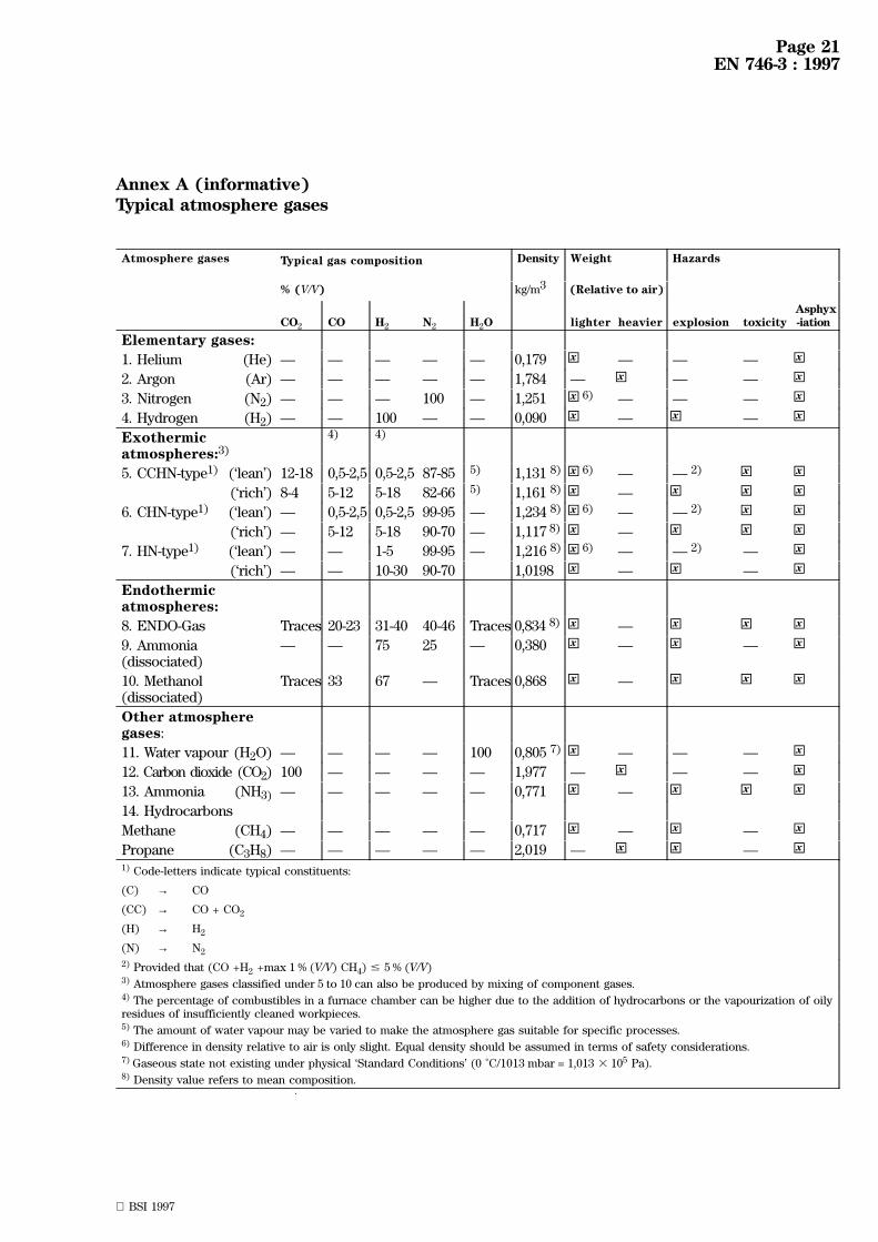
Annex A (informative)Typical atmosphere gases
Atmosphere gases Typical gas composition Density Weight Hazards
% (V/V) kg/m3 (Relative to air)
CO2 CO H2 N2 H2O lighter heavier explosion toxicityAsphyx-iation
Elementary gases:
1. Helium (He) Ð Ð Ð Ð Ð 0,179 x× Ð Ð Ð x×2. Argon (Ar) Ð Ð Ð Ð Ð 1,784 Ð x× Ð Ð x×3. Nitrogen (N2) Ð Ð Ð 100 Ð 1,251 x× 6) Ð Ð Ð x×4. Hydrogen (H2) Ð Ð 100 Ð Ð 0,090 x× Ð x× Ð x×Exothermicatmospheres:3)
4) 4)
5. CCHN-type1) (`lean') 12-18 0,5-2,5 0,5-2,5 87-85 5) 1,131 8) x× 6) Ð Ð 2) x× x×(`rich') 8-4 5-12 5-18 82-66 5) 1,161 8) x× Ð x× x× x×
6. CHN-type1) (`lean') Ð 0,5-2,5 0,5-2,5 99-95 Ð 1,234 8) x× 6) Ð Ð 2) x× x×(`rich') Ð 5-12 5-18 90-70 Ð 1,117 8) x× Ð x× x× x×
7. HN-type1) (`lean') Ð Ð 1-5 99-95 Ð 1,216 8) x× 6) Ð Ð 2) Ð x×(`rich') Ð Ð 10-30 90-70 1,0198 x× Ð x× Ð x×
Endothermicatmospheres:
8. ENDO-Gas Traces 20-23 31-40 40-46 Traces 0,834 8) x× Ð x× x× x×9. Ammonia(dissociated)
Ð Ð 75 25 Ð 0,380 x× Ð x× Ð x×
10. Methanol(dissociated)
Traces 33 67 Ð Traces 0,868 x× Ð x× x× x×
Other atmospheregases:
11. Water vapour (H2O) Ð Ð Ð Ð 100 0,805 7) x× Ð Ð Ð x×12. Carbon dioxide (CO2) 100 Ð Ð Ð Ð 1,977 Ð x× Ð Ð x×13. Ammonia (NH3) Ð Ð Ð Ð Ð 0,771 x× Ð x× x× x×14. Hydrocarbons
Methane (CH4) Ð Ð Ð Ð Ð 0,717 x× Ð x× Ð x×Propane (C3H8) Ð Ð Ð Ð Ð 2,019 Ð x× x× Ð x×1) Code-letters indicate typical constituents:
(C) → CO
(CC) → CO + CO2
(H) → H2
(N) → N2
2) Provided that (CO +H2 +max 1 % (V/V) CH4) # 5 % (V/V)3) Atmosphere gases classified under 5 to 10 can also be produced by mixing of component gases.4) The percentage of combustibles in a furnace chamber can be higher due to the addition of hydrocarbons or the vapourization of oilyresidues of insufficiently cleaned workpieces.5) The amount of water vapour may be varied to make the atmosphere gas suitable for specific processes.6) Difference in density relative to air is only slight. Equal density should be assumed in terms of safety considerations.7) Gaseous state not existing under physical `Standard Conditions' (0 ÊC/1013 mbar = 1,013 3 105 Pa).8) Density value refers to mean composition.

Page 22EN 746-3 : 1997
BSI 1997
Annex B (informative)
Explosion hazards of gas mixtures containing combustiblesFigure 1 shows typical gas compositions as a result of the sub-stoichiometric combustion of fuel gases (propane,natural gas, etc.) as it is supplied for the generation of various types of controlled gas atmospheres. The aim ofthis figure is to add to an understanding of the defined safety threshold values (in terms of critical gasconstituents) on which the strategies to avoid the risk of explosion are based.
The dividing line between flammable and self-sustaining combustible is variable. It depends not only on thecomposition of the gas and its ignition temperature but also on external conditions such as the dissipation ofheat at the point of combustion, the temperature and the exit velocity of the gas.
It should be noted that flammable gases which are not sustaining combustion in accordance with this definitioncan be capable of forming explosive mixtures. A gas which fails to combust under test cannot automatically beassumed to be harmless.
Figure B.1 Typical gas composition/Partial combustion of a fuel gas with air

Page 23EN 746-3 : 1997
BSI 1997
Annex C (informative)
Inert gas purgingFigure C.1 illustrates the relationship between the reduction of oxygen (starting with 20,9 % (V/V) in accordancewith oxygen in air) as a function of the inert purge gas volume (related to the volume of the chamber/enclosure)during a typical purging procedure at ambient temperature using an inert gas (non-reactive with oxygen,preferably Nitrogen N2).
The threshold value of 1 % (V/V) oxygen (as specified in 3.4) theoretically requires a purging gas volume which isequal to 3-times the volume of the chamber/enclosure on condition that complete mixing occurs. The establishedvalue of safety purge volume (5-times the chamber volume, ref. 3.10) includes a safety margin, thus takingaccount of practical operation conditions which can deviate somewhat from ideal conditions. Short circuits ofthe gas flow and so-called `dead spots' (parts of the enclosure not fully included in the flow pattern) must beavoided. Gas inlets/outlets should be adequately positioned and where fitted gas circulation should be activated.
Particular attention should be paid to the adequate supply of purge gas. It is important that both throughputvolume of gas and the duration of the purging procedure are being monitored. Analytical monitoring of a criticalgas constituent (e.g. oxygen content) can be required in specialized cases.
Figure C.1 Concentration of oxygen vs. purge gas volume

Page 24EN 746-3 : 1997
BSI 1997
Annex D (informative)
Bibliography
Country Document title
(B) A.G.B/3 GT 1/Fascicule V:(Fours sous atmospheÁre controà leÂe)(Furnaces under protective atmosphere)
(CH) Schweizerische Unfallversicherungsanstalt/UnfallverhuÈ tung:Richtlinien zur VerhuÈ tung von UnfuÈ llen und Vergiftungen bei der thermischen Behandlung vonMetallen(ReÁgles pour la preÂvention des accidents et intoxications lors du traitement thermique desmeÂtaux)(Guidelines for the prevention of accidents and poisoning during thermal treatment of metals)
(D) AWT-Fachausschuss 8:Sicherheitstechnische Empfehlungen fuÈ r den Betrieb von IndustrieoÈ fen mit SchutzgasatmosphuÈren(Industrial furnaces with controlled atmospheres)
VDI Richtlinie 2046:Sicherheitstechnische Richtlinie fuÈ r den Betrieb von IndustrieoÈ fen mit Schutz- undReaktionsgasatmosphuÈren(Safety code for operation of industrial furnaces with protective and reaction gases)
(F) APAVE T 127-7.65:`Recommendations for safe use of gases in industrial furnaces.'Recommandations en vue de l'emploi des gaz combustibles riches dans les fours industriels.
(I) UNI 7728:`Forni industriali - Diretiva per la sicurezza'(Industrial furnaces - safety rules)
(UK) IM/9 Code of practice/Part 1:`Exothermic atmosphere gas generators'.IM/9 Code of practice/Part 2:`Endothermic atmosphere gas generators'.IM/9 Code of practice/Part 3:`Use of generated atmosphere gas in associated plant'.

Page 25EN 746-3 : 1997
BSI 1997
Annex E (informative)Used definitions
Trilingual index
E.1 English Ð German Ð French
Ref. English German French
3.11 atmosphere gas generatingsystem
Schutz- undReaktionsgaserzeugungssystem
geÂneÂrateur de gaz d'atmospheÁre
3.12 automatic re-start Automatisches Wiederanfahren redeÂmarrage automatique
3.16 flame failure Flammenausfall deÂfaut de flamme
3.13 flame instability FlammeninstabilitaÈt instabilite de flamme
3.17 flame safeguard FlammenuÈberwachungseinrichtung dispositif de surveillance deflamme
3.14 flame sensor FlammenfuÈhler deÂtecteur de flamme
3.18 flame trap Flammensperre dispositif anti-retour de flamme
3.4 flammable atmosphere gas Brennbares Schutz- undReaktionsgas
gaz d'atmospheÁre inflammable
3.8 fluid Fluid fluide
3.1 industrial thermoprocessingand associated equipment
Industrielle Thermoprozeûanlagenund damit verbundeneEinrichtungen
eÂquipement thermique industriel etannexes
3.6 inert gas Inertgas gaz inerte
3.23 interrupted pilot ZuÈndbrenner, mit unterbrochenerBetriebsweise
bruà leur d'allumage intermittent
3.20 multiturn valve Ventil mit Mehrfachumdrehung vanne multitours
3.5 non-flammable atmospheregas
Nichtbrennbares Schutz-undReaktionsgas
gaz d'atmospheÁre non inflammable
3.21 non-return valve RuÈckschlagventil vanne anti-retour
3.22 pilot flame ZuÈndflamme flamme d'allumage
3.24 pilot shrinkage Flammenreduzierung bruà leur d'allumage en bas reÂgime
3.3 purging SpuÈ len purge
3.2 safe ignition temperature Sicherheitstemperatur tempeÂrature d'allumage en touteseÂcuriteÂ
3.9 safe level of vacuum Sicherheitsvakuum niveau suffisant de vide assurantla seÂcuriteÂ
3.26 safe shut-down Sichere Abschaltung arreÃt de seÂcuriteÂ
3.25 safe start check Sicherheitsstartkontrolle controà le de seÂcurite au deÂmarrage
3.10 safety purge volume Sicherheits-SpuÈ lvolumen volume de purge assurant laseÂcuriteÂ
3.28 safety shut-off valve system Sicherheitsabschalt-Ventilsystem systeÁme de vannes d'arreÃtd'urgence
3.15 sensor output drift Signaldrift deÂrive du deÂtecteur
3.29 slam shut valve Schnellschluûventil vanne aÁ fermeture rapide parpression
3.30 start gas flame Startflamme flamme de deÂmarrage
3.19 Start-up interlock Startverriegelung dispositif de verrouillage audeÂmarrage
3.27 system of safety shut-down Sicherheitsabschaltsysteme systeÁme d'arreÃt de seÂcuriteÂ
3.7 toxic atmosphere gas Giftiges Schutz- und Reaktionsgas gaz d'atmospheÁre toxique

Page 26EN 746-3 : 1997
BSI 1997
E.2 German Ð English Ð French
Ref. German English French
3.12 Automatisches Wiederanfahren automatic re-start redeÂmarrage automatique
3.4 Brennbares Schutz- undReaktionsgas
flammable atmosphere gas gaz d'atmospheÁre inflammable
3.16 Flammenausfall flame failure deÂfaut de flamme
3.14 FlammenfuÈhler flame sensor deÂtecteur de flamme
3.13 FlammeninstabilitaÈt flame instability instabilite de flamme
3.24 Flammenreduzierung pilot shrinkage bruà leur d'allumage en bas reÂgime
3.18 Flammensperre flame trap dispositif anti-retour de flamme
3.17 FlammenuÈberwachungseinrichtung flame safeguard dispositif de surveillance deflamme
3.8 Fluid fluid fluide
3.7 Giftiges Schutz- und Reaktionsgas toxic atmosphere gas gaz d'atmospheÁre toxique
3.1 Industrielle Thermoprozeûanlagenund damit verbundeneEinrichtungen
industrial thermoprocessing andassociated equipment
eÂquipement thermique industrielet annexes
3.6 Inertgas inert gas gaz inerte
3.5 Nichtbrennbares Schutz- undReaktionsgas
non-flammable atmosphere gas gaz d'atmospheÁre noninflammable
3.21 RuÈckschlagventil non-return valve vanne anti-retour
3.29 Schnellschluûventil slam shut valve vanne aÁ fermeture rapide parpression
3.11 Schutz- und Reaktionsgaserzeugungssystem
atmosphere gas generatingsystem
geÂneÂrateur de gaz d'atmospheÁre
3.26 Sichere Abschaltung safe shut-down arreÃt de seÂcuriteÂ
3.27 Sicherheitsabschaltsysteme system of safety shut-down systeÁme d'arreÃt de seÂcuriteÂ
3.28 Sicherheitsabschalt-Ventilsystem safety shut-off valve system systeÁme de vannes d'arreÃtd'urgence
3.10 Sicherheits-SpuÈ lvolumen safety purge volume volume de purge assurant laseÂcuriteÂ
3.25 Sicherheitsstartkontrolle safe start check controà le de seÂcurite audeÂmarrage
3.2 Sicherheitstemperatur safe ignition temperature tempeÂrature d'allumage en touteseÂcuriteÂ
3.9 Sicherheitsvakuum safe level of vacuum niveau suffisant de vide assurantla seÂcuriteÂ
3.15 Signaldrift sensor output drift deÂrive du deÂtecteur
3.3 SpuÈ len purging purge
3.30 Startflamme start gas flame flamme de deÂmarrage
3.19 Startverriegelung Start-up interlock dispositif de verrouillage audeÂmarrage
3.20 Ventil mit Mehrfachumdrehung multiturn valve vanne multitours
3.23 ZuÈndbrenner, mit unterbrochenerBetriebsweise
interrupted pilot bruà leur d'allumage intermittent
3.22 ZuÈndflamme pilot flame flamme d'allumage

Page 27EN 746-3 : 1997
BSI 1997
E.3 French Ð English Ð German
Ref. French English German
3.26 arreÃt de seÂcurite safe shut-down Sichere Abschaltung
3.24 bruà leur d'allumage en bas reÂgime pilot shrinkage Flammenreduzierung
3.23 bruà leur d'allumage intermittent interrupted pilot ZuÈndbrenner, mit unterbrochenerBetriebsweise
3.21 vanne anti-retour non-return valve RuÈckschlagventil
3.25 controà le de seÂcurite audeÂmarrage
safe start check Sicherheitsstartkontrolle
3.16 deÂfaut de flamme flame failure Flammenausfall
3.15 deÂrive du deÂtecteur sensor output drift Signaldrift
3.14 deÂtecteur de flamme flame sensor FlammenfuÈhler
3.18 dispositif anti-retour de flamme flame trap Flammensperre
3.17 dispositif de surveillance deflamme
flame safeguard FlammenuÈberwachungseinrichtung
3.19 dispositif de verrouillage audeÂmarrage
Start-up interlock Startverriegelung
3.1 eÂquipement thermique industrielet annexes
industrial thermoprocessing andassociated equipment
IndustrielleThermoprozeûanlagen und damitverbundene Einrichtungen
3.22 flamme d'allumage pilot flame ZuÈndflamme
3.30 flamme de deÂmarrage start gas flame Startflamme
3.8 fluide fluid Fluid
3.4 gaz d'atmospheÁre inflammable flammable atmosphere gas Brennbares Schutz-undReaktionsgas
3.5 gaz d'atmospheÁre noninflammable
non-flammable atmosphere gas Nichtbrennbares Schutz-undReaktionsgas
3.7 gaz d'atmospheÁre toxique toxic atmosphere gas Giftiges Schutz- und Reaktionsgas
3.6 gaz inerte inert gas Inertgas
3.11 geÂneÂrateur de gaz d'atmospheÁre atmosphere gas generatingsystem
Schutz- undReaktionsgaserzeugungssystem
3.13 instabilite de flamme flame instability FlammeninstabilitaÈt
3.9 niveau suffisant de vide assurantla seÂcuriteÂ
safe level of vacuum Sicherheitsvakuum
3.3 purge purging SpuÈ len
3.12 redeÂmarrage automatique automatic re-start Automatisches Wiederanfahren
3.27 systeÁme d'arreÃt de seÂcurite system of safety shut-down Sicherheitsabschaltsysteme
3.28 systeÁme de vannes d'arreÃtd'urgence
safety shut-off valve system Sicherheitsabschalt-Ventilsystem
3.2 tempeÂrature d'allumage en touteseÂcuriteÂ
safe ignition temperature Sicherheitstemperatur
3.29 vanne aÁ fermeture rapide parpression
slam shut valve Schnellschluûventil
3.20 vanne multitours multiturn valve Ventil mit Mehrfachumdrehung
3.10 volume de purge assurant laseÂcuriteÂ
safety purge volume Sicherheits-SpuÈ lvolumen

Page 28EN 746-3 : 1997
BSI 1997
Annex ZA (informative) Clauses of this European Standard addressing essentialrequirements or other provisions of EU DirectivesThis European Standard has been prepared under a mandate given to CEN by the European Commission and theEuropean Free Trade Association and supports essential requirements of following EU Directives:
Machinery Directive 89/392/EEC,
its amendments 91/368/EEC, 93/44/EEC and 93/68/EEC
Low Voltage Directive 73/23/EEC
WARNING: Other requirements and other EU Directives may be applicable to the product(s) falling within thescope of this standard.
Compliance with the clauses of this standard provides one means of conforming with the specific essentialrequirements of the Directive concerned and associated EFTA regulations.

BSI 1997
BS EN 746-3 : 1997
List of references
See national foreword.
BSI389 Chiswick High RoadLondonW4 4AL
|||||||||||||||||||||||||||||||||||||||||||||||||||||||||||||||||||||||||||||||||||||||||||||||||||||||||||||||||||||||||||||||
BSI Ð British Standards Institution
BSI is the independent national body responsible for preparing British Standards. Itpresents the UK view on standards in Europe and at the international level. It isincorporated by Royal Charter.
Revisions
British Standards are updated by amendment or revision. Users of British Standardsshould make sure that they possess the latest amendments or editions.
It is the constant aim of BSI to improve the quality of our products and services. Wewould be grateful if anyone finding an inaccuracy or ambiguity while using thisBritish Standard would inform the Secretary of the technical committee responsible,the identity of which can be found on the inside front cover. Tel: 020 8996 9000.Fax: 020 8996 7400.
BSI offers members an individual updating service called PLUS which ensures thatsubscribers automatically receive the latest editions of standards.
Buying standards
Orders for all BSI, international and foreign standards publications should beaddressed to Customer Services. Tel: 020 8996 9001. Fax: 020 8996 7001.
In response to orders for international standards, it is BSI policy to supply the BSIimplementation of those that have been published as British Standards, unlessotherwise requested.
Information on standards
BSI provides a wide range of information on national, European and internationalstandards through its Library and its Technical Help to Exporters Service. VariousBSI electronic information services are also available which give details on all itsproducts and services. Contact the Information Centre. Tel: 020 8996 7111.Fax: 020 8996 7048.
Subscribing members of BSI are kept up to date with standards developments andreceive substantial discounts on the purchase price of standards. For details ofthese and other benefits contact Membership Administration. Tel: 020 8996 7002.Fax: 020 8996 7001.
Copyright
Copyright subsists in all BSI publications. BSI also holds the copyright, in the UK, ofthe publications of the international standardization bodies. Except as permittedunder the Copyright, Designs and Patents Act 1988 no extract may be reproduced,stored in a retrieval system or transmitted in any form or by any means ± electronic,photocopying, recording or otherwise ± without prior written permission from BSI.
This does not preclude the free use, in the course of implementing the standard, ofnecessary details such as symbols, and size, type or grade designations. If thesedetails are to be used for any other purpose than implementation then the priorwritten permission of BSI must be obtained.
If permission is granted, the terms may include royalty payments or a licensingagreement. Details and advice can be obtained from the Copyright Manager.Tel: 020 8996 7070.