bstructure report
TRANSCRIPT

ARC2213 Building Structures Project 1: Fettuccine Truss Bridge Analysis Report
BUILDING STRUCTURES (ARC 2523) PROJECT 1
FETTUCCINE TRUSS BRIDGE ANALYSIS REPORT
GARNETTE DAYANG ROBERT 0315491
OOI ZHI QIAN 0313999
CHUNG WEI JIN 0313789
LEONG HUI YI 0319280
ABDUL MAHI MUHSIN 0314421
DANAR JOVIAN ADITIYA VADYA PUTRA 0314575

ARC2213 Building Structures Project 1: Fettuccine Truss Bridge Analysis Report

ARC2213 Building Structures Project 1: Fettuccine Truss Bridge Analysis Report
CONTENTS 1. INTRODUCTION 1.1 AIMS & OBJECTIVES 2. METHODOLOGY 2.1 MAKING OF FETTUCCINE BRIDGE
2.2 REQUIREMENT 3. PRECEDENT STUDY 4. MATERIALS & EQUIPMENTS 4.1 STRENGTH OF MATERIAL 4.1.1 PROPERTIES OF FETTUCCINE 4.1.2 TESTING OF FETTUCCINE 4.1.3 EXPERIMENTS 4.1.4 CONCLUSION 4.2 ADHESIVE ANALYSIS 5. BRIDGE TESTING AND LOAD ANALYSIS 5.1 TIMELINE 5.2 FIRST BRIDGE 5.3 SECOND BRIDGE 5.4 THIRD BRIDGE 5.5 FOURTH BRIDGE 6. FINAL BRIDGE 6.1 AMENDMENTS 6.2 FINAL MODEL MAKING 6.3 JOINT ANALYSIS 6.4 FINAL BRIDGE TESTING AND LOAD ANALYSIS 6.5 CALCULATIONS 7. CONCLUSION 8. APPENDIX 8.1 CASE STUDY 1 8.2 CASE STUDY 2 8.3 CASE STUDY 3 8.4 CASE STUDY 4 8.5 CASE STUDY 5 8.6 CASE STUDY 6 9. REFERENCES

ARC2213 Building Structures Project 1: Fettuccine Truss Bridge Analysis Report
1.0 INTRODUCTION Truss is a structure built up of three or more members that are normally considered being pinned and hinged at the joints. The following figure shows different types of trusses. Load applied to the truss is transmitted to joint so that each individual member is in either pure tension or compression. 1.1 AIMS & OBJECTIVES This project aims to develop our understanding of tensile and compressive strength of construction materials by understanding the distribution of force in a truss and to design a perfect truss bridge of high level of aesthetic value and minimal construction material. In order to achieve that, in a group of 6 we were required to carry out a precedent study on a truss bridge of our choice, analyzing the connections, arrangements, design and orientations of the members. After that, we were required to design and construct a fettuccine bridge of 350mm clear span and maximum weight of 80g. These requirements are to be met, and the bridge will be then tested to fail. After that, we then need to analyze the reason of its failure and calculate its efficiency.

ARC2213 Building Structures Project 1: Fettuccine Truss Bridge Analysis Report
2.0 METHODOLOGY 2.1 MAKING OF FETTUCCINE BRIDGE STRENGTH OF MATERIAL Understanding the strength of the fettuccine is important in order to build one bridge that can carry a maximum load. For the tensile strength in the fettuccine is considerably low when comparing to aluminum, which has the same amount of stiffness to the fettuccine. ADHESIVE Choosing the best type of adhesive is important as it plays a huge role in this assignment. As there are many types of adhesive, that each has their own function and characteristic. Not only the type of it, but the brand itself is important as it has different quality and choosing one that suits constructing fettuccine bridge is primary. MODEL MAKING To ensure precision in our model making, we drafted the drawings in AutoCad and it was drawn in 1:1 scale, and we plotted out to ensure precision and to ease our process. Each pasta was marked individually and placed at their own location and length and were glued accordingly to strengthen our bridge. MODEL TESTING Models were then being tested by placing a hook and a pail hanging under the bridge. Water was being poured into the pail slowly and all these were being recorded to allow us to fix and amend and analyze our bridge. 2.2 REQUIREMENTS
-‐ A clear span of 350mm -‐ Maximum weight of 80g -‐ Bridge must be made out of fettuccine -‐ Allowed to use any type of adhesive -‐ Design and workmanship is put to consideration as part of aesthetic

ARC2213 Building Structures Project 1: Fettuccine Truss Bridge Analysis Report
3.0 PRECEDENT STUDY The precedence study below is used as reference knowledge for our understanding of forces, real truss bridge connections, arrangement and orientation of both horizontal and vertical members. The analyzed information is applied in constructing our final model through a series of trial and error. Information is obtained from different internet sources as well as books.
HISTORIC NAME: WADELL ‘A’ TRUSS BRIDGE
LOCATION: ENGLISH LANDING PARK, PARKVILLE, MISSOURI ENGINEER: JOHN ALEXANDER LOW WADDELL (1854-1938) A BRIEF HISTORY
Originally built as a railroad bridge across Linn Branch Creek, in the
vicinity of Trimble, Clinton County, Missouri, it now crosses Rush Creek carrying a pedestrian path between a day-use recreational area and two isolated ball fields. It is a triangular shaped, steel, through-truss, bridge approximately 100 feet long and 40 feet high. It rests on two concrete abutments and is composed of pin-connected riveted units. In 1980, the bridge was disassembled and stored for seven years by the U. S. Army Corps of Engineers, while awaiting a suitable location and a responsible owner. Despite its relocation, the Waddell "A" Truss Bridge retains its integrity of design as drawn by its creator, John Alexander Low.
ARC2213 Building Structures Project 1: Fettuccine Truss Bridge Analysis Report
PHYSICAL DESCRIPTION
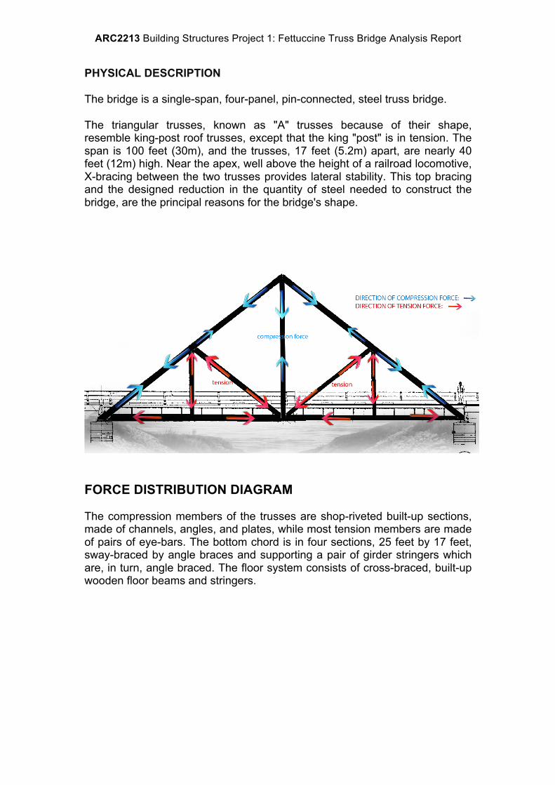
The bridge is a single-span, four-panel, pin-connected, steel truss bridge.
The triangular trusses, known as "A" trusses because of their shape, resemble king-post roof trusses, except that the king "post" is in tension. The span is 100 feet (30m), and the trusses, 17 feet (5.2m) apart, are nearly 40 feet (12m) high. Near the apex, well above the height of a railroad locomotive, X-bracing between the two trusses provides lateral stability. This top bracing and the designed reduction in the quantity of steel needed to construct the bridge, are the principal reasons for the bridge's shape.
FORCE DISTRIBUTION DIAGRAM
The compression members of the trusses are shop-riveted built-up sections, made of channels, angles, and plates, while most tension members are made of pairs of eye-bars. The bottom chord is in four sections, 25 feet by 17 feet, sway-braced by angle braces and supporting a pair of girder stringers which are, in turn, angle braced. The floor system consists of cross-braced, built-up wooden floor beams and stringers.

ARC2213 Building Structures Project 1: Fettuccine Truss Bridge Analysis Report
TRUSS CONNECTIONS and MEMBERS

ARC2213 Building Structures Project 1: Fettuccine Truss Bridge Analysis Report

ARC2213 Building Structures Project 1: Fettuccine Truss Bridge Analysis Report
COMPARISON OF THE BRIDGE BEFORE RELOCATION
Railroad bridge across Linn Branch Creek, 1989 ( Before dissembling )

ARC2213 Building Structures Project 1: Fettuccine Truss Bridge Analysis Report
DETAIL IMAGES A) B) C)
A) Detail View Of Circa 1952 Steel Approach Beams Taken From
Underneath Bridge B) Detail Of Support Column Looking At Right Angle To Truss C) Detail View Of Bracing Around Support Column
DETAILED TRUSS CONNECTION REFERENCE OF MEMBERS
ARC2213 Building Structures Project 1: Fettuccine Truss Bridge Analysis Report
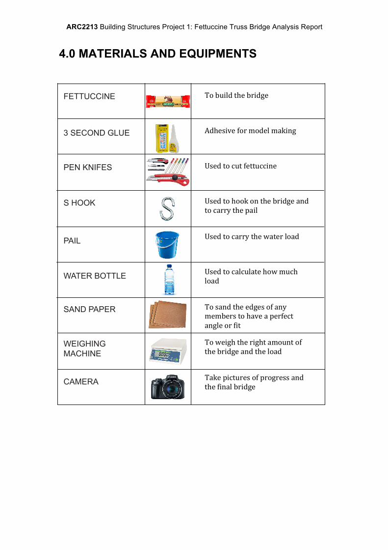
4.0 MATERIALS AND EQUIPMENTS
FETTUCCINE
3 SECOND GLUE
PEN KNIFES
S HOOK
PAIL
WATER BOTTLE
SAND PAPER
WEIGHING MACHINE
CAMERA
To build the bridge
Adhesive for model making
Used to cut fettuccine
Used to hook on the bridge and to carry the pail
Used to carry the water load
Used to calculate how much load
To sand the edges of any members to have a perfect angle or fit
To weigh the right amount of the bridge and the load
Take pictures of progress and the final bridge

ARC2213 Building Structures Project 1: Fettuccine Truss Bridge Analysis Report
4.1 STRENGTH OF MATERIAL Fettuccine was the only material approved to be used for the bridge for this project. Thus, research and analysis of Fettuccine was conducted before the model making session. 4.1.1 PROPERTIES OF FETTUCCINE Before using the fettuccine, it needs to be checked and filtered out, those that are twisted cannot be used; it is to ensure that the load is able to distribute evenly and effectively through the flat surface of the fettuccine. Dimension: 250mm x 5mm Tensile strength: 2 000 psi Stiffness (E= stress/strain): 10 000 000 psi 4.1.2 TESTING OF FETTUCCINE Before testing, we made sure the fettuccine were glued with the proper technique to prevent uneven surface and to ensure the ease of building.
FIgure 4.1.2.1 Wrong way of gluing fettuccine
FIgure 4.1.2.2 Correct gluing technique for the
members
FIgure 4.1.2.3 Correct gluing technique for the
beam

ARC2213 Building Structures Project 1: Fettuccine Truss Bridge Analysis Report
4.1.3 EXPERIMENTS The fettuccine was arranged in so many ways, and we’ve found the best way, which was the staggered arrangement, it helps us to ensure that the breaking points were not aligned, hence its stronger. Also to understand its efficiency and the maximum load each can carry, we’ve tested several types of beams with different placements and ways to understand which is the best to be implemented in our bridge. Layers of Members
Length of Fettuccine (cm)
Clear Span (m)
Load Sustained (Vertical Facing) (g)
Load Sustained (Horizontal Facing) (g)
1 Layer 26 15 420 205 2 Layers 26 15 500 320 3 Layers 26 15 770 630 4 Layers (I-beam)
26 15 1300 1110
4.1.4 CONCLUSION Based on the testing, the I-beam (4 layers of members) is the strongest, both horizontal and vertical positions can be put in use. When the vertical member is placed in between two horizontal members, the horizontal members will enhance the load distributions and the load will transfer to the vertical member that can withstand more loads. The 3 layers was not used as it was just carrying extra weight but not effective enough to hold any load. For the 2 layers, it was strong enough and light weight to carry the loads. As for the first one, it was not used, as it couldn’t hold any load.

ARC2213 Building Structures Project 1: Fettuccine Truss Bridge Analysis Report
4.2 ADHESIVE ANALYSIS Four different kinds of glue used to ensure the joints were strong and thus strengthen the bridge. Types of Adhesive
Advantages Disadvantages Rank
V-Tech Super Glue -High efficiency -Fast setting -Low viscosity
-Burns skin -Makes fettuccine brittle -Leaves marks on fettuccine
1
UHU Glue -Easy to use -Neat
-Low efficiency -Slow setting time
3
YAMAYO Super Glue
-High efficiency -Strong and neat -Fast setting time
-Expensive 2
V-Tech Super Glue was used the most while constructing the fettuccine bridge. It has high efficiency and it dried faster than other adhesives, as it is more concentrated when compared to the rest. The glue was allowed to dry out for a minute or two in order to ensure the glue to dry out and let the bridges to perform at its best capabilities. Yamayo Super Glue was also used a lot as it was very easy and also strong and neater, but because it was expensive and not much in one bottle we decided to stick with V-Tech. Furthermore it provides the same strength as V-Tech. UHU glue was tried once and it was not as good as the rest. It required longer time to dry and making it very flexible. Not strong enough to hold loads. In conclusion, the V-tech Super Glue were much more effective when combining the joints as well as stacking the layers of the fettuccine as it was much more efficient, easier to use and it dries out very quickly. In order for the bridge to reach its maximum potential strength, the bridge was left to dry out for hours before being tested.

ARC2213 Building Structures Project 1: Fettuccine Truss Bridge Analysis Report
5.0 BRIDGE TESTING & LOAD ANALYSIS 5.1 PROGRESS TIMELINE

ARC2213 Building Structures Project 1: Fettuccine Truss Bridge Analysis Report
5.2 FIRST BRIDGE FIRST BRIDGE The first bridge model that we tested was based on the precedent studies of the ‘Howe Truss’. In this first experiment, we did two different kinds of ways of hooking the load onto the bridge as can be seen in figure 1.1 and figure 1.2.
Figure 1.1 First bridge model
Figure 1.2 Single S-hook was attached to the middle part of the horizontal member

ARC2213 Building Structures Project 1: Fettuccine Truss Bridge Analysis Report
Figure 1.3 Failed horizontal member (Single s-hook) The structural failure in figure 1.2 occurs at the horizontal member because the member that bears the most load was too thin and it bears the load all by itself without distributing it equally through the structure. Bridge Weight: 64g Maximum load capacity: 1.6kg Efficiency: (1600)^2 = 40% 0.064

ARC2213 Building Structures Project 1: Fettuccine Truss Bridge Analysis Report
5.2.1 Calculations

ARC2213 Building Structures Project 1: Fettuccine Truss Bridge Analysis Report
new doc 7_1.jpg

ARC2213 Building Structures Project 1: Fettuccine Truss Bridge Analysis Report

ARC2213 Building Structures Project 1: Fettuccine Truss Bridge Analysis Report
5.3 SECOND BRIDGE The second bridge model was based on the ‘Baltimore Truss’ precedence study. Some amendments were made for this bridge, by adding more cross bracings in order to distribute the tension force more equally along the structure, reducing the possibilities of it breaking. We also improved the top and bottom chords by replacing them with I-beams. The I-beams were constructed with 3 layers of fettuccines.
Figure 2 Cross bracings were made when constructing the second bridge
Figure 2.1 Top and bottom chords were improved with I-beams

ARC2213 Building Structures Project 1: Fettuccine Truss Bridge Analysis Report
Figure 2.1 and Figure 2.3 Failed horizontal members Figure 2.1 and 2.3 shows structural failure that occurred at the horizontal member. The failure was similar to the first bridge test, where it occurred in the horizontal member. This is due to the fact that the S-hook was placed in the middle of the horizontal member and too much load was concentrated on that particular spot. Moreover, the fettuccine were not thick enough to withstand the force, causing it to break apart. Much improvement was made from the previous test, as this bridge could withstand loads of up to 5.4kg, 3.8kg more than the previous bridge. This is due to the I-beams that were constructed along the top and bottom chords. Bridge Weight: 62g Maximum load capacity: 5.4kg Efficiency: (5400)^2 = 47.03% 0.062

ARC2213 Building Structures Project 1: Fettuccine Truss Bridge Analysis Report
5.4 THIRD BRIDGE After the first two tests, we decided to change our truss design into the Wadell ‘A’ truss bridge. This is because we want to explore more on the possibilities of a stronger structure than the previous models. I-beams design was constructed lighter than the previous model, with only 2 layers of fettuccines. This is to make the whole structure lighter and to fulfill the requirements of the project.
Figure 3 Third bridge model
Figure 3.1 Load distribution diagram Amendments were made whereby positions of the S-hook were changed from the center of the bridge towards the both sides of the trusses as can be seen in figure 3.2 in order to distribute the compression and tension load equally on both trusses.

ARC2213 Building Structures Project 1: Fettuccine Truss Bridge Analysis Report
Figure 3.4 Failed members of the bridge
Figure 3.3 and 3.4 shows structural failure, which occurred on many members of the bridge (Cross bracings, bottom chords and one side of the top chord). The placement of the S-hooks in this experiment plays a huge role on the structural failures. The cross bracings were too small to withstand the tension and compression force, causing both bottom chords to break apart. Poor workmanship on constructing the diagonal members has an effect too as they are not connected properly, hence the poor load distribution along the members. Bridge Weight: 50g Maximum load capacity: 2.3kg Efficiency: (2300)^2 = 105.8% 0.050
Figure 3.2 Placements of S-hooks on both sides of the trusses
Figure 3.3 X bracings were constructed

ARC2213 Building Structures Project 1: Fettuccine Truss Bridge Analysis Report
5.5 FOURTH BRIDGE We decided to stick with the same truss design for the fourth bridge, with amendments made with the cross bracings as well as improved workmanship the joints of the diagonal members. Cross bracings were made longer than the previous experiment in order for it to withstand the tension forces.
Figure 4 fourth experimental models with improved cross bracings

ARC2213 Building Structures Project 1: Fettuccine Truss Bridge Analysis Report
Figure 4.1 Double S-hook attached to both trusses
Figure 4.2 Breakage of the bridge during test
Figure 4.13 Occurrence of structural failures

ARC2213 Building Structures Project 1: Fettuccine Truss Bridge Analysis Report
Figure 4.3 shows structural failures, where it occurred on the diagonal members as well as the bottom chord. This occurred due to the compression and tension forces. With poor workmanship of the joints of the diagonal members, joints were weak and were easy to break apart. The I-beam on the bottom chord was constructed in two separate pieces, where joints of it were weak and caused it to break apart. Bridge Weight: 73g Maximum load capacity: 7.79kg Efficiency: (7790)^2 = 83.13% 0.073

ARC2213 Building Structures Project 1: Fettuccine Truss Bridge Analysis Report
6.0 FINAL BRIDGE 6.1 AMENDMENTS Final Bridge
6.2 FINAL MODEL MAKING
After going through a few times of trial experiments on the draft bridges, we managed to finalize the structure and joints of our bridge. Also, we made sure that the efficiency of the final structure was on point to its maximum by increasing its strength in terms of the constant weight. So, here is how our final bridge, that weighted 69kg with its ability to hold a bucket of water that had a weight of 9.1kg in total, was made.
We started off with the individual bridge parts that will be used to build up the whole bridge model. Using the strongest 3 seconds super glue, we placed two layers of fettuccini sticks together for each part until it is enough for the whole structure. The two-layered part was then left ready to be cut accordingly to the desired measurements based on the outline of the bridge. For each frame of the bridge structure, we placed one layer of fettuccini stick on the top and bottom side of the uncut two-layered structure to create an I-beam-like structure.
We printed out the outline of our bridge structure that was drawn on the AutoCAD software. In order to achieve the maximum accuracy of the structure, we placed the two-layered sticks and the I-beams on the outline sheet and cut the sticks according to the lengths of each structural parts of the bridge. Then, we placed the readied parts back on the outline sheet to stick up the edges to create the form of the bridge. We started off from the sides of the bridge followed by its top and bottom.

ARC2213 Building Structures Project 1: Fettuccine Truss Bridge Analysis Report
6.3 JOINT ANALYSIS The joint methods that are used in the construction of the bridge is very important as it affects the efficiency and failure of the final fettuccine bridge. The joints are thoroughly tested and studied in order to achieve the maximum strength in each connection of members. Below are the final joint methods that were used in our bridge, according to the requirement of each part.

ARC2213 Building Structures Project 1: Fettuccine Truss Bridge Analysis Report
JOINT A DIAGONAL/VERTICAL LOAD DISTRIBUTING MEMBERS
From analyzing the forces, we found out that the top of the structural frame experiences compression forces upon application of load. The vertical member helps to balance out the force as it has an internal tension force and transfers the load to the adjacent diagonal member and to the bottom of the structural frame. This reduces the stress on the I beam as the vertical member now functions as a supporting column for the I-beam. JOINT B MIDDLE MEMBER AS ‘SUPPORT’ COLUMN
The central vertical member of the bridge is joined very carefully so that it stands perfectly in the centre of the mitre joint of the I-beam, acting as a mean of support and prevents the top member from collapsing. We
found of that, when the vertical member is even slightly off balance from the centre, it causes stress to the structure above

ARC2213 Building Structures Project 1: Fettuccine Truss Bridge Analysis Report
JOINT C TOP CONNECTION OF I-BEAM (STRUCTURAL FRAME)
The diagonal members of the structural frame ( I-beams ), are joined with a mitre joint. A mitre joint is joint made by beveling each of two parts to be joined, usually at a 45° angle, to form a corner, usually a 90° angle. The rigidity of the structural frame is strengthened due to this design, and provides stability and strength to the loads acting on it from the structures below, and helps to evenly distribute the forces. JOINT D TOP DIAGONAL TO BASE, FRAME CONNECTION OF I-BEAM
Since the top part of the structural frame is in full compression, and the bottom part is in tension, the force needs to have a proper path to flow along the structure. To accommodate this huge compression force, the top structure needs to be carefully shaped and connected to the base without any faulty/disconnected edges. In order to do that, the I-beam member is cut at a 45’ angle as it adheres perfectly to the bottom member. This provides better resistance to the structure against compressive stress.

ARC2213 Building Structures Project 1: Fettuccine Truss Bridge Analysis Report
JOINT E The vertical connecting members are very critical in the bridge design as means of supporting as well as distributing the load along the entire structure. The improvement is made from a very first design where we placed the horizontal member merely against a single vertical member. The horizontal member did not aid in transferring the load to the other members however was only dependent on the adhesive (three second glue) that was used. This resulted in an instant breakage of the horizontal member. The second design was improved by placing the horizontal members on top of the structural base frame, on either sides of the vertical member. This gave support to the vertical member as well as increasing the surface distance horizontally. However it did not transfer the load vertically. The final design was improvised by using two diagonal members touching the center vertical member. This helped to divert the load stress evenly to the other parts of the bridge.

ARC2213 Building Structures Project 1: Fettuccine Truss Bridge Analysis Report
JOINT F In order to further strengthen the base members, a horizontal member was placed on either side of the diagonal members that were supporting the vertical members. This helped to reduce the stress on the diagonal members and prevented it from sliding or breaking off (distortion) from the vertical member. These members also helped to distribute the loads horizontally from one side to the other. The edges of the
connection are carefully shaped so as to fit perfectly into the slots between the base structural frame and diagonal members, to provide extra strength and rigidity. BASE JOINTS JOINT G HORIZONTAL ‘X’ BRACING ( JOINT TO THE STRUCTURAL FRAME )
Joint H is using the concept of how I-beams are coped inside each other with one member’s flange resting on the other. This provides a ‘lock ‘mechanism for the horizontal beam and gives it some strength. Two diagonal bracings are placed below the two-parallel members, in order to strengthen the beam

ARC2213 Building Structures Project 1: Fettuccine Truss Bridge Analysis Report
JOINT G & I HORIZONTAL ‘X’ BRACING ( JOINT TO THE HORIZONTAL BRACING )

ARC2213 Building Structures Project 1: Fettuccine Truss Bridge Analysis Report
6.4 Final Bridge Testing and Load Analysis The picture below shows the final design of our fettuccine bridge and its load distribution. In this bridge, the final amendments made are the number of diagonal members in the structure and an addition of a cross bracing in the base to strengthen the bridge from torsion.
Figure () Final bridge design showing the distribution of compression and
tension force in the bridge.
Figure () Top view of the bridge
Figure () Base Design

ARC2213 Building Structures Project 1: Fettuccine Truss Bridge Analysis Report
Figure() Bridge while testing.
Figure () Top chords of bridge broke and caused the bridge to fall
After observing, calculating and analyzing our final bridge, we came to a conclusion that the failure of this bridge is due to the breakage of the top chords which had to withstand a huge amount of compression forces. Longer members tend to have a weaker resistance to compression force which might also be one of the reasons to the failure to our bridge as the top chords are both 215mm each. Moreover, Joint BE and Joint IJ, which are diagonal members are also under large compression forces which are 133.41N each, further weakening the support of the bridge.In addition to that, the middle member is also under large compression force, which is 202.91N, causing a large upward force acting on the top and bottom chords, resulting in torsion in both of these members.

ARC2213 Building Structures Project 1: Fettuccine Truss Bridge Analysis Report
Figure () Highlighted are the failed members.
Bridge weight: 74g Load: 8670g Efficiency: (8.67) =1015.80% The efficiency of the final bridge was over our expectations as the maximum load that our final testing bridge withstood was 7790g which was 880g lighter than the final load withstood. If the large amount of compression force could be lessen down to a smaller amount, the bridge could have resulted in a higher efficiency than this. Moreover, if the middle member was acted on by a tension force instead of compression force, The top chords and bottom chords would have lesser force acting on them in the middle, resulting in higher efficiency. Failed Components Top chords and bottom chords. Failed Reasons Large compression force acting on
top chords and bottome chords exerted from middle member of the fettuccine bridge.
2 0.074

ARC2213 Building Structures Project 1: Fettuccine Truss Bridge Analysis Report
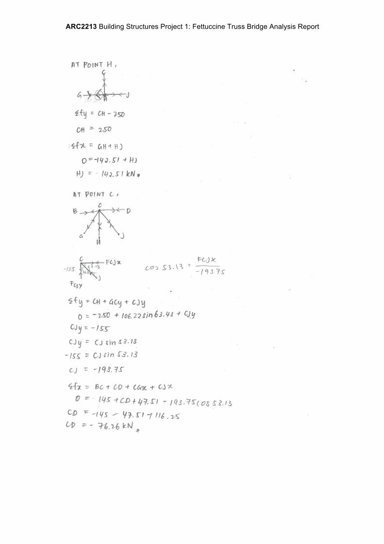
6.5 Calculations

ARC2213 Building Structures Project 1: Fettuccine Truss Bridge Analysis Report

ARC2213 Building Structures Project 1: Fettuccine Truss Bridge Analysis Report

ARC2213 Building Structures Project 1: Fettuccine Truss Bridge Analysis Report

ARC2213 Building Structures Project 1: Fettuccine Truss Bridge Analysis Report
7.0 CONCLUSION
In a group of 6, we have carried out experiment and tested 5 bridges in total. Each of them has different truss and different efficiency is tested out. The precedent study that we have taken inspiration and modified from is the “Waddell A Truss Bridge”.
After rounds of testing and calculating the efficiency, we have decided to make our bridge triangular shape because the equivalent triangle is the strongest form in withstanding pressure. In the process of changing the truss and pattern, we realize that the angle too, plays a crucial part in sharing the load and having clear state of how tension and compression work in different methods.
In the last few rounds of finalizing the bridge shape, we decided to keep it simple because the more truss added in, the weaker it actually gets because these trusses act as additional and useless weight that serve no purpose except adding the total loads. Thus, we make it to the easiest and obvious triangle shape with the same length and same angle on inverted side. At the end, it’s efficiency increases way more than our first try. As a team, we learnt that time management is very important as we need time to carried out countless experiments and also calculating the efficiency and highest possibilities of either which bridge can withstand the most weight. We also learnt that the unity of all team members can make the workload lesser and also make the progress faster when all of us corporate well together as a team.

ARC2213 Building Structures Project 1: Fettuccine Truss Bridge Analysis Report
8.0 APPENDIX CASE STUDY NO. 1 JANE OOI ZHI QIAN 0313999

ARC2213 Building Structures Project 1: Fettuccine Truss Bridge Analysis Report

ARC2213 Building Structures Project 1: Fettuccine Truss Bridge Analysis Report

ARC2213 Building Structures Project 1: Fettuccine Truss Bridge Analysis Report
CASE STUDY NO. 2 MEGAN CHUNG WEI JIN 03

ARC2213 Building Structures Project 1: Fettuccine Truss Bridge Analysis Report
ARC2213 Building Structures Project 1: Fettuccine Truss Bridge Analysis Report

ARC2213 Building Structures Project 1: Fettuccine Truss Bridge Analysis Report

ARC2213 Building Structures Project 1: Fettuccine Truss Bridge Analysis Report

ARC2213 Building Structures Project 1: Fettuccine Truss Bridge Analysis Report
CASE STUDY NO. 3 ABDUL MAHI MUHSIN 0314421

ARC2213 Building Structures Project 1: Fettuccine Truss Bridge Analysis Report

ARC2213 Building Structures Project 1: Fettuccine Truss Bridge Analysis Report

ARC2213 Building Structures Project 1: Fettuccine Truss Bridge Analysis Report

ARC2213 Building Structures Project 1: Fettuccine Truss Bridge Analysis Report

ARC2213 Building Structures Project 1: Fettuccine Truss Bridge Analysis Report
CASE STUDY NO. 4 GARNETTE DAYANG ROBERT 0315491

ARC2213 Building Structures Project 1: Fettuccine Truss Bridge Analysis Report

ARC2213 Building Structures Project 1: Fettuccine Truss Bridge Analysis Report
CASE STUDY NO. 25 LEONG HUIYI 0319280

ARC2213 Building Structures Project 1: Fettuccine Truss Bridge Analysis Report

ARC2213 Building Structures Project 1: Fettuccine Truss Bridge Analysis Report

ARC2213 Building Structures Project 1: Fettuccine Truss Bridge Analysis Report
CASE STUDY NO. 6 DANAR JOVIAN ADITIYA PUTRA 0314575

ARC2213 Building Structures Project 1: Fettuccine Truss Bridge Analysis Report

ARC2213 Building Structures Project 1: Fettuccine Truss Bridge Analysis Report

ARC2213 Building Structures Project 1: Fettuccine Truss Bridge Analysis Report

ARC2213 Building Structures Project 1: Fettuccine Truss Bridge Analysis Report

ARC2213 Building Structures Project 1: Fettuccine Truss Bridge Analysis Report

ARC2213 Building Structures Project 1: Fettuccine Truss Bridge Analysis Report
9.0 REFERENCES
Vitaltechnical.com,. 'Sealant Manufacturer In Malaysia | Adhesive | Vital Technical'. N.p., 2015. Web. 8 Oct. 2015.
Ching, Francis D.K (2008) Building Construction Illustrated Fourth Edition. New Jersey: John Wiley & Sons, Inc.