buck 2012 catalog
DESCRIPTION
Buck Chuck CatalogTRANSCRIPT
P R O D U C T C A T A L O G
www.buckchuck.com

Depth in Experience, Unparalleled Service and Price to Performance.That’s Why!
ATSC 3 & 6-Jaw Ajust-Tru® Scroll Chuck
Super Life Power Chuck
4-Jaw Independent Chuck
Direct OEM Replacement Power ChuckAir Operated High Precision Power Chuck
Our chucks offer the quality and performance you have come to expect from Buck Chuck. Quality like this comes with over 75 years of experience and unparalleled customer service.
That's why you want a Buck!
If a chuck’s a chuck, then… why a Buck?

Page
Table of Contents
General Info Replacing Your Obsolete Buck Chuck – Crossover Sheet ...................................................................................................... 4 Chuck Selection ................................................................................................................................................................ 5 Parts Breakdown ............................................................................................................................................................... 6 Spindle Identification ......................................................................................................................................................... 7ATSC Manual Scroll Chucks Ajust-Tru® Style 3 and 6-Jaw Forged Steel Scroll Chuck Hardened Top Reversible Jaw .................................................................................. 8 3 and 6-Jaw Forged Steel Scroll Chuck Hardened Solid Jaw ................................................................................................ 9 4-Jaw Forged Steel Scroll Chuck Hardened Top Reversible Jaw.......................................................................... ................ 10 5C Adapted 3 or 6-Jaw Forged Steel Scroll Chuck Hardened Top Reversible or Solid Jaw.................................................... 10 ATSC Mounting Plates ..................................................................................................................................................... 11 AT/BVC Manual Scroll Chucks Ajust-Tru® Style AT 3 and 6-Jaw Forged Steel Scroll Chuck Hardened Top Reversible or Solid Jaw ............................................................... 13 BVC 3 and 6-Jaw Semi-Steel Scroll Chuck Hardened Top Reversible Jaw ........................................................................... 14 AT/BVC Mounting Plates .................................................................................................................................................. 15Independent Chucks 4-Jaw Independent Chuck ............................................................................................................................................... 17 Independent Mounting Plates ........................................................................................................................................... 18 A1 & A2 4-Jaw Independent Direct Mount Chuck .............................................................................................................. 19 D1 4-Jaw Independent Direct Mount Chuck ...................................................................................................................... 20Power Chucks SPAC Air Operated High Precision Power Chuck ................................................................................................................ 22 3-Jaw Air Operated Power Chuck ..................................................................................................................................... 23 3-Jaw Stationary Self Contained Closed Center Power Chuck ............................................................................................ 24 3-Jaw High Speed Thru-Hole Draw Tube Operated Power Chuck ........................................................................................ 25 4-Jaw High Speed Thru-Hole Draw Tube Operated Power Chuck ........................................................................................ 26 3-Jaw High Speed Closed Center Drawbar Operated Power Chuck..................................................................................... 27 Stationary Hydraulic/Pneumatic Super-Life Power Chuck ................................................................................................... 28 Hydraulic Super Life Power Chuck ................................................................................................................................... 29 2/3-Jaw Combination Super Life Power Chuck ................................................................................................................. 30 Pull-Back Power Chuck ................................................................................................................................................... 31 Buck Forkardt Quick Change Chucks Power Chucks Type FNC .................................................................................................................................................. 32 Manual Chucks Type F+ .................................................................................................................................................. 32 Tork-Lok Arbors and Collets Installation and Operating Instructions .............................................................................................................................. 34 Arbor Applications ........................................................................................................................................................... 35 Drawbar Models Long Series ........................................................................................................................................... 36 Drawbar Models Short Series ........................................................................................................................................... 38 Long Series Collets.......................................................................................................................................................... 40 Short Series Collets ......................................................................................................................................................... 41 Replacement Components ............................................................................................................................................... 42 Air-Operated Models ....................................................................................................................................................... 42 Manual Fixtures .............................................................................................................................................................. 43

AT+ MODEL CHUCKSThe chart above refers to the replacement options for the obsolete AT+ model of chucks. The ATSC was designed as a replacement for this chuck – the components are not interchangeable but the ATSC can be mounted to the existing adapter plate from your AT+ chuck.
If you currently have an AT+ with any of the numbers in columns A or B, it is replaced by a chuck in column C. Please contact us at 1-800-228-BUCK for more information.
AT MODEL CHUCKS The chart above refers to the replacement options for the obsolete AT model of chucks. The new model of the AT was designed as a replacement for this chuck – the components are not interchangeable, but it can be mounted to the existing adapter plate from your obsolete AT chuck.
If you currently have an AT with any of the numbers in columns A, B or C, it is replaced by a chuck in column D.
** Parts do not have a direct replacement but there are alternate replacement options available that may require you to purchase a new adapter plate. Please contact us at 1-800-228-BUCK for more information.
Obsolete Chuck Crossover
AT+ MODELS
AT+ Model # AT+ Part # Replacement Part #
A B C
3AT+4 A0100176977 B8043S
6AT+4 A0100211977 B8046S
3AT+5 A0100177977 B8053S
6AT+5 A0100212977 B8056S
3AT+6 A0100178977 B8063S
6AT+6 A0100213977 B8066S
3AT+6R A0100178978 B8063
6AT+6R A0100213978 B8066
3AT+8 A0100179977 B8083S
6AT+8 A0100214977 B8086S
3AT+8R A0100179978 B8083
6AT+8R A0100214978 B8086
3AT+10 A0100180977 B8103S
6AT+10 A0100215977 B8106S
3AT+10R A0100180978 B8103
6AT+10R A0100215978 B8106
3AT+12 A0100181977 B8123S
6AT+12 A0100216977 B8126S
3AT+12R A0100181978 B8123
6AT+12R A0100216978 B8126
3AT+15R A0100182978 B8153
6AT+15R A0100217978 B8156
AT MODELS
AT Model # AT Serial # AT Part # Replacement Part #
A B C D
3AT4 A1434 1434 B8043S**
6AT4 A1462 1462 B8046S**
3AT5 A2535 2535 B8053S**
6AT5 A2562 2562 B8056S**
3AT6 A0002063003 3634 B8063S**
6AT6 A0002066003 3662 B8066S**
3AT6R A0002063002 2063R AT063R
6AT6R A0002066002 2066R AT066R
3AT8 A0002083003 4831 B8083S**
6AT8 A0002086003 4862 B8086S**
3AT8R A0002083002 2083R AT083R
6AT8R A0002086002 2086R AT086R
3AT10 A0002103003 5103 B8103S**
6AT10 A0002106003 5106 B8106S**
3AT10R A0002103002 2103R AT103R
6AT10R A0002106002 2106R AT106R
3AT12 A0002124003 5124 B8123S**
6AT12 A0002127003 5127 B8126S**
3AT12R A0002124002 2124R AT123R
6AT12R A0002127002 2127R AT126R
3AT15R A0002154002 2154R AT153R
6AT15R A0002157002 2157R AT156R
4

www.BuckChuckUSA.com1-800-228-BUCK
Obsolete Chuck Crossover
Chuck Selection
ATSC AT/BVC4-JAW
INDEPENDENT
APPLICATIONS:
• Precision machining• Large quantity productions•Higher RPM needs
APPLICATIONS:
• Tool room applications•Grinding
APPLICATIONS:
• Tool room applications•Grinding•Odd-shaped parts
How do you determine what type of chuck and mounting plate is required for the application?
What size of chuck?• For scroll chucks, do not exceed the swing diameter over the
cross slide• For independent chucks, the next larger size may work
What accuracy and repeatability is required?•High precision – the ATSC chucks provide .0005 TIR on
duplicate parts•General I.D. or O.D. work – the BVC chucks provide .001 TIR on
duplicate parts
How many jaws are required?• 2-Jaw – special applications• 3-Jaw – conventional machining• 4-Jaw – square and offset work• 6-Jaw – 2nd operation or thin wall parts
What type of jaw is needed?• The most common are the top reversible jaws. These can be
used for both I.D. or O.D. work and production work•2-piece jaw chucks can be adapted to soft jaws or special
top tooling• Solid jaws are typically used for tool room applications
What mounting is needed?•Determine spindle type using the spindle identifier on page 7•Measure the major diameter of the taper and match to the chart
for the spindle type (page 7)• For threaded spindles, you will need to measure threads per inch
5

4
11
17
16
12
2
13
3
5
8
10
9
1
18
14
157
6
Parts Breakdown
BVC
No. Name of parts
1 Chuck Body
2 Back Cover
3 Scroll Plate
4 Pinion
5 Pinion Screw
6 Hard Master Jaw
7 Hard Top Jaw
8 Grease Nipple
9 Chuck Mounting Bolt
10 Back Cover Mounting Bolts
11 Chuck Wrench with Safety Spring
12 Back Cover Locating Pin
13 Back Cover Mounting Bolt
14 Top Jaw Mounting Bolt
15 Top Jaw Mounting Bolt
16 Fine Adjustment Screw
ATSC
No. Name of parts
1 Chuck Body
2 Scroll Plate
3 Top Jaw
4 Master Jaw
5 Pinion
6 Back Cover
7 Chuck Wrench
8 Stud Bolt
9 Hexagon Socket Head Cap Screw
10 Grease Nipple
11 Chuck Mounting Bolt
12 Adjust Screw
13 Safety Spring
14 Hex Wrench
15 Jaw Mounting Bolt
16 Hex Wrench
17 Hex Wrench
AT
No. Name of parts
1 Chuck Body
2 Back Cover
3 Scroll Plate
4 Pinion
5 Pinion Retainer
6 Master Jaw
7 Top Jaw
8 Grease Nipple
9 Chuck Mounting Bolt
10 Chuck Mounting Bolt
11 Chuck Wrench with Safety Spring
12 Back Cover Mounting Bolt
13 Back Cover Mounting Bolt
14 Top Jaw Mounting Bolt
15 Top Jaw Mounting Bolt
16 Fine Adjustment Screw
17 Hex Wrench
18 Hex Wrench NOTE: 10"–15" BVC Chucks have alternate parts. Please contact our sales office for more information.
ATSC
AT
13
12
3
161
6
7
15
14
10
9
8
5
4
2
11
BVC
6

www.BuckChuckUSA.com1-800-228-BUCK
Parts Breakdown Spindle IdentificationFor Mounting Plates
"A""B"
"C""E1"
"E2"
"F1"
"F2"
7°7'30"
"A"
"B"
"C"
8°17'50"
"A"
KEY
"A""B"
"C""E"
7°7'30"
"F"
SPINDLE TYPE A1 & A2
Spindle noseA B C (MAX) E1 & E2 F1 F2
A-4 2.500 0.437 7/16”-14 3.250 -----
A-5 3.251 0.563 7/16”-14 4.125 2.437
A-6 4.188 0.625 1/2”-13 5.250 3.250
A-8 5.501 0.688 5/8”-11 6.750 4.375
A-11 7.751 0.750 3/4”-10 9.250 6.500
A-15 11.251 0.813 7/8”-9 13.000 9.750
A-20 16.251 0.875 1”-8 18.250 14.500
A-28 23.001 1.000 1-1/4”-7 25.500 10.438
L SPINDLE TYPE LONG TAPER KEY DRIVE
Spindle noseA
THREADB
C
KEY
L00 3-3/4”-6 2.000 3/8 X 3/8 X 1-1/2
L0 4-1/2”-6 2.375 3/8 X 3/8 X 1-3/4
L1 6”-6 2.875 5/8 X 5/8 X 2-3/8
L2 7-3/4”-5 3.375 3/4 X 3/4 X 2-7/8
L3 10-3/8”-4 3.875 1.00 X 1.00 X 3-1/4
THREADED SPINDLE TYPE
Spindle nose threadA
1”-8
1”-10
1-1/2”-8
1-3/4”-8
2-1/4”-8
2-3/8”-6
2-3/4”-8
D1 CAMLOCK SPINDLE TYPE
Spindle noseA B C (MAX) CAMSTUD
DIA “E” F
D1-3 2.125 0.437 9/16 2.782
D1-4 2.500 0.437 5/8 3.250
D1-5 3.251 0.500 3/4 4.125
D1-6 4.188 0.625 7/8 5.250
D1-8 5.501 0.688 1 6.750
D1-11 7.751 0.750 1-3/16 9.250
D1-15 11.251 0.813 1-3/8 13.000
7

Forged Steel Body Scroll ChuckModel ATSC Hardened Top Reversible Jaws
FEATURES & BENEFITS:• 4 micro-fine adjustment screws allow .0005” TIR repeatability•High-quality forged steel body construction allows for higher lathe speeds•Hardened and ground scroll is precision balanced, allowing longer life and
greater accuracy•Hardened jaws and pinions increase life of the chuck• American standard tongue & groove master jaws allow for greater
flexibility in choice of top tooling
CHUCK SHIPS COMPLETE WITH:•Master and hardened top reversible jaws• Spring loaded T-wrench• Allen wrench•Mounting bolts
*6” chuck jaws are not ANSI standard – please contact us for details.
ATSC W/MASTER & HARDENED TOP REVERSIBLE JAWS
Dia. Part No. A B C D E F G H J K L M N P QGripping Dia. (in.) Max
RPMWt.Lb.EXT. INT.
*6" B8066 6.50 2.76 4.92 5.51 1.78 0.48 M10x1.5P 2.58 1.00 1.54 0.35 0.31 M10x1.5P 1.69 5/16 0.98-5.51 2.95-5.91 3450 23
8" B8086 7.87 3.15 6.30 6.93 2.37 0.48 M10x1.5P 3.57 1.25 2.05 0.43 0.31 M10x1.5P 1.75 3/8 0.79-7.87 2.56-7.09 3000 40
10" B8106 10.04 3.58 7.87 8.82 3.23 0.50 M12x1.75P 3.75 1.50 2.59 0.47 0.31 M10x1.5P 2.13 1/2 0.98-9.45 3.54-8.86 2250 73
12" B8126 12.60 3.90 10.24 11.26 4.14 0.58 M16x2P 4.41 1.75 2.57 0.55 0.35 M12x1.75P 2.50 1/2 1.57-11.22 4.53-11.22 1725 117
15" B8156 15.75 4.96 12.99 14.25 5.51 0.59 M16x2P 5.55 2.50 3.61 0.67 0.35 M12x1.75P 3.00 3/4 1.57-14.17 5.12-14.17 1350 253
6-JAW
ATSC W/MASTER & HARDENED TOP REVERSIBLE JAWS
Dia. Part No. A B C D E F G H J K L M N P Q Gripping Dia. (in.) MaxRPM
Wt. Lb.EXT. INT.
*6" B8063 6.50 2.76 4.92 5.51 1.78 0.48 M10x1.5P 2.58 1.00 1.54 0.35 0.31 M10x1.5P 1.69 5/16 0.31-5.51 2.17-5.91 4600 23
8" B8083 7.87 3.15 6.30 6.93 2.37 0.48 M10x1.5P 3.57 1.25 2.05 0.43 0.31 M10x1.5P 1.75 3/8 0.39-7.87 2.17-7.09 4000 37
10" B8103 10.04 3.58 7.87 8.82 3.23 0.50 M12x1.75P 3.75 1.50 2.59 0.47 0.31 M10x1.5P 2.13 1/2 0.47-9.45 3.35-8.86 3000 69
12" B8123 12.60 3.90 10.24 11.26 4.14 0.58 M16x2P 4.41 1.75 2.57 0.55 0.35 M12x1.75P 2.50 1/2 0.71-11.22 4.92-11.22 2300 110
15" B8153 15.74 4.96 12.99 14.25 5.51 0.59 M16x2P 5.55 2.50 3.61 0.67 0.35 M12x1.75P 3.00 3/4 0.79-14.17 5.12-14.17 1800 246
3-JAW
Measurements in inches unless otherwise indicated.
8

www.BuckChuckUSA.com1-800-228-BUCK
Forged Steel Body Scroll ChuckModel ATSC Hardened Solid Jaws
FEATURES & BENEFITS:• 4 micro-fine adjustment screws allow .0005” TIR repeatability•High-quality forged steel body construction allows for higher lathe speeds•Hardened and ground scroll is precision balanced, allowing longer life and greater accuracy•Hardened jaws and pinions increase life of the chuck•Hardened solid jaws allow for smaller gripping ranges as opposed to 2-piece jaw chucks
CHUCK SHIPS COMPLETE WITH:• Inside and outside gripping solid jaws• Spring loaded T-wrench• Allen wrench•Mounting bolts
3-JAW
ATSC W/INSIDE & OUTSIDE SOLID JAWS
Dia. Part No. A B C D E F G H J K L M NGripping Dia. (in.) Max
RPMWt. Lb.EXT. INT.
4" B8043S 4.07 2.38 2.80 3.53 1.04 0.42 M5x0.8P 1.62 0.44 0.75 0.24 0.24 M8x1.25P 0.08-2.76 0.98-2.95 6300 9
5" B8053S 5.20 2.54 3.74 4.25 1.28 0.41 M8x1.25P 1.88 0.63 0.80 0.32 0.26 M8x1.25P 0.08-3.54 1.42-3.74 5500 13
6" B8063S 6.50 2.76 4.92 5.51 1.78 0.48 M10x1.5P 2.52 0.74 0.96 0.35 0.31 M10x1.5P 0.12-5.51 2.05-5.71 4600 23
8" B8083S 7.87 3.15 6.30 6.93 2.37 0.48 M10x1.5P 3.50 0.95 1.37 0.43 0.31 M10x1.5P 0.16-6.30 2.36-6.69 4000 39
10" B8103S 10.04 3.58 7.87 8.82 3.23 0.50 M12x1.75P 3.62 1.23 1.83 0.47 0.31 M10x1.5P 0.24-8.27 2.95-8.66 3000 72
12" B8123S 12.60 3.90 10.24 11.26 4.14 0.58 M16x2P 4.25 1.48 1.75 0.55 0.35 M12x1.75P 0.39-10.04 3.35-9.94 2300 115
ATSC W/INSIDE & OUTSIDE SOLID JAWS
Dia. Part No. A B C D E F G H J K L M NGripping Dia. (in.) Max
RPMWt. Lb.EXT. INT.
4" B8046S 4.07 2.36 2.80 3.53 1.04 0.42 M5x0.8P 1.62 0.41 0.75 0.24 0.24 M8x1.25P 0.08-2.76 0.98-2.95 4725 9
5" B8056S 5.20 2.54 3.80 4.25 1.28 0.41 M8x1.25P 1.88 0.63 0.80 0.32 0.26 M8x1.25P 0.08-3.54 1.42-3.74 4125 14
6" B8066S 6.50 2.76 4.92 5.51 1.78 0.48 M10x1.5P 2.52 0.74 0.96 0.35 0.31 M10x1.5P 0.24-5.51 2.36-5.71 3450 25
8" B8086S 7.87 3.15 6.30 6.93 2.37 0.48 M10x1.5P 3.50 0.95 1.37 0.43 0.31 M10x1.5P 0.39-6.30 2.76-6.69 3000 44
10" B8106S 10.04 3.58 7.87 8.82 3.23 0.50 M12x1.75P 3.62 1.23 1.83 0.47 0.31 M10x1.5P 0.59-8.27 2.76-8.66 2600 80
12" B8126S 12.60 3.90 10.24 11.26 4.14 0.58 M16x2P 4.25 1.48 1.75 0.55 0.35 M12x1.75P 0.79-10.04 3.35-9.94 1725 117
6-JAW Measurements in inches unless otherwise indicated.
9

Forged Steel Body Scroll ChuckModel ATSC Hardened Top Reversible Jaws
FEATURES & BENEFITS:• 4 micro-fine adjustment screws allow .0005” TIR repeatability•High-quality forged steel body construction allows for higher lathe speeds•Hardened and ground scroll is precision balanced, allowing longer life and
greater accuracy•Hardened jaws and pinions increase life of the chuck• American standard tongue & groove master jaws allow for greater
flexibility in choice of top tooling
CHUCK SHIPS COMPLETE WITH:•Master and hardened top reversible jaws• Spring loaded T-wrench• Allen wrench•Mounting bolts
**Please note that this is a SCROLL chuck. All jaws move together, NOT independently (if you need an independent chuck, see page 17).
FEATURES & BENEFITS:• 4 micro-fine adjustment screws allow .0005” TIR repeatability•High-quality forged steel body construction allows for higher lathe speeds• Hardened and ground scroll is precision balanced, allowing longer life and greater accuracy•Hardened jaws and pinions increase life of the chuck• Used in tail stocks for jobs where centers cannot be used• Adapter does not rotate
Chuck dimensions can be found on pages 8 and 9.
CHUCK SHIPS COMPLETE WITH:•Jaws•5Cadapter•SpringloadedT-wrench•Allenwrench•Mountingbolts
*6” chuck jaws are not ANSI standard – please contact us for details.
*6” chuck jaws are not ANSI standard – please contact us for details.
*
*
*
5C ADAPTED AJUST-TRU® CHUCKS
Part # Jaw Style Chuck Dia.(in.)
Chuck Body Height (in.) Shank Flange
(in.)Adapter Hole Dia
(in.)Adapter
Length (in.) Thread
B8043S-5C Solid 3-Jaw 4.07 2.38 5C 4 0.866 4.41 11/4-20
B8053S-5C Solid 3-Jaw 5.20 2.54 5C 5 0.866 4.41 11/4-20
B8063S-5C Solid 3-Jaw 6.50 2.76 5C 6 0.866 4.41 11/4-20
B8046S-5C Solid 6 -aw 4.07 2.38 5C 4 0.866 4.41 11/4-20
B8056S-5C Solid 6-Jaw 5.20 2.54 5C 5 0.866 4.41 11/4-20
B8066S-5C Solid 6-Jaw 6.50 2.76 5C 6 0.866 4.41 11/4-20
*B8063-5C 2 pc 3-Jaw 6.50 2.76 5C 6 0.866 4.41 11/4-20
*B8066-5C 2 pc 6-Jaw 6.50 2.76 5C 6 0.866 4.41 11/4-20
*B8064-5C 2 pc 6-Jaw 6.50 2.76 5C 6 0.866 4.41 11/4-20
3/6-JAW
ATSC W/MASTER & HARDENED TOP REVERSIBLE JAWS
Dia. Part No. A B C D E F G H J K L M N P QGripping Dia. (in.)
EXT. INT.MaxRPM
Wt.Lb.
*6" B8064 6.50 2.76 4.92 5.51 1.78 0.48 M10x1.5P 2.58 1.00 1.54 0.35 0.31 M10x1.5P 1.69 5/16 0.31-5.51 2.17-5.91 4600 23
8" B8084 7.87 3.15 6.30 6.93 2.37 0.48 M10x1.5P 3.57 1.25 2.05 0.43 0.31 M10x1.5P 1.75 3/8 0.39-7.87 2.17-7.09 4000 38
10" B8104 10.04 3.58 7.87 8.82 3.23 0.50 M12x1.75P 3.75 1.50 2.59 0.47 0.31 M10x1.5P 2.13 1/2 0.47-9.45 3.35-8.86 3000 71
12" B8124 12.60 3.90 10.24 11.26 4.14 0.58 M16x2P 4.41 1.75 2.57 0.55 0.35 M12x1.75P 2.50 3/4 0.71-11.22 4.92-11.22 2300 130
4-JAW Measurements in inches unless otherwise indicated.
10

www.BuckChuckUSA.com1-800-228-BUCK
Mounting Plates for Hardinge Lathes
ATSC Scroll Chuck Mounting PlatesAdapt to all 3, 6 & 4-Jaw ATSC Models and AT+ Models
See Spindle Identification on page 7 to determine the correct mounting plate needed.
AMERICAN STANDARD • STYLE A1 & A2
Spindle Size
Chuck Size
4 5 6 8 10 12 15
3 A4-A3 A5-A3 A6-A3 - - -
4 - A5-A4 A6-A4 A8-A4 - - -
5 - - A6-A5 A8-A5 A10-A5 - -
6 - - A6-A6 A8-A6 A10-A6 A12-A6 -
8 - - A6-A8 A8-A8 A10-A8 A12-A8 A15-A8
11 - - - - - A12-A11 A15-A11
HARDINGE 4 DEGREE TAPER MOUNTING PLATES
Chuck Size 5 6
Id # A5-4DEG A6-4DEG
HARDINGE 2 3/16"-10 THREADED MOUNTING PLATES
Chuck Size 5 6
Id # A100451000 A100452000
AMERICAN STANDARD • STYLE D1 CAMLOCK
Spindle Size
Chuck Size
4 5 6 8 10 12 15
3 A4-D3 A5-D3 A6-D3 - - -
4 - A5-D4 A6-D4 A8-D4 - - -
5 - - A6-D5 A8-D5 A10-D5 - -
6 - - A6-D6 A8-D6 A10-D6 A12-D6 -
8 - - A6-D8 A8-D8 A10-D8 A12-D8 A15-D8
11 - - - - - A12-D11 A15-D11
11

ATSC Scroll Chuck Mounting PlatesAdapt to all 3, 6 & 4-Jaw ATSC Models
See Spindle Identification on page 7 to determine the correct mounting plate needed.
Measurements in inches unless otherwise indicated.
AMERICAN STANDARD • LONG TAPER STYLE L
Spindle Size
Chuck Size
6 8 10 12 15
L-00 A6-L00 A8-L00 A10-L00 – –
L-0 A6-L0 A8-L0 A10-L0 A12-L0 –
L-1 – A8-L1 A10-L1 A12-L1 A15-L1
L-2 – – – A12-L2 A15-L2
L-3 – – – – A15-L3
THREADED MOUNTING PLATES
Spindle Size
Chuck Size
4 5 6 8 10 12
1 1/2"-8 A100433000 A100434000 A100435000 – – –
1 3/4"-8 – A100437000 A100438000 – – –
2 1/4"-8 – – A100439000 A100440000 A100441000 –
2 3/8"-6 – – A100442000 A100443000 A100444000 A100445000
2 3/4"-8 – – – A100446000 A100447000 A100448000
5C MOUNTING PLATES
Chuck Size Part No. Shank Flange Hole Dia. Length Thread
4 A04-5C 5C 4” 0.866 4.41 1 1/4-20
5 A05-5C 5C 5” 0.866 4.41 1 1/4-20
6 A06-5C 5C 6” 0.866 4.41 1 1/4-20
HRT ROTARY TABLE PLATES
Spindle Chuck Size Part Number
HRT110 4" A4-HRT110
HRT160 6" A6-HRT160
HRT210 8" A8-HRT210
HRT310 10" A10-HRT310
12

www.BuckChuckUSA.com1-800-228-BUCK
Use inner bolt circle for 10" to 15" chuck sizes.
Forged Steel BodyModel AT Hardened Top Reversible Jaws
AT HARDENED TOP REVERSIBLE JAWS
AT HARDENED TOP REVERSIBLE JAWS
Dia. Part No. A B C D E F G H J K L N P Q Gripping Dia. (in) MaxRPM
Wt. lb.EXT. INT.
6" AT063R 6.00 2.32 3.13 5.34 1.54 0.69 1/4-20 2.58 1.00 1.56 0.31 1/2-30 1.69 5/16 0.12-5.00 1.89-5.75 3400 16
8" AT083R 8.27 3.12 4.75 7.50 2.26 0.75 3/8-16 3.57 1.25 2.08 0.5 3/4-16 1.75 3/8 0.24-6.77 2.13-6.77 3100 42
10" AT103R 10.00 3.49 6.38 4.38 2.84 0.80 7/16-14 3.75 1.50 2.56 0.56 3/14-16 2.13 1/2 0.51-9.37 2.95-8.70 2700 66
12" AT123R 12.00 3.98 7.91 5.25 3.27 0.80 1/2-13 4.41 1.75 2.61 0.63 3/4-16 2.50 1/2 0.52-11.30 3.27-10.12 2200 110
15" AT153R 15.00 5.36 11.78 6.75 4.25 1.06 5/8-11 5.55 2.50 3.44 0.75 3/4-16 3.00 3/4 0.55-15.00 3.98-15.71 1500 221
6-JAW
3-JAW
FEATURES & BENEFITS:• .0004" repeatability on duplicate parts due to .020" of
clearance between the chuck cavity and mounting plate hub• Forged steel body allows for higher lathe speeds•Hardened and ground scroll is balanced for higher accuracy• Jaws are hardened and ground for longer life
CHUCK SHIPS COMPLETE WITH:•Master and hardened top reversible jaws• Spring loaded T-wrench•Mounting bolts
Measurements in inches unless otherwise indicated.
Dia. Part No. A B C D E F G H J K L N P Q Gripping Dia. (in) MaxRPM
Wt. lb.EXT. INT.
6" AT066R 6.00 2.32 3.13 5.34 1.54 0.69 1/4-20 2.58 1 1.56 0.31 1/2-30 1.69 5/16 0.12-5.00 1.89-5.75 3400 19
8" AT086R 8.27 3.12 4.75 7.50 2.26 0.75 3/8-16 3.57 1.25 2.08 0.50 3/4-16 1.75 3/8 0.24-6.77 2.13-6.77 3100 50
10" AT106R 10.00 3.49 6.38 4.38 2.84 0.80 7/16-14 3.75 1.5 2.56 0.56 3/14-16 2.13 1/2 0.51-9.37 2.95-8.70 2700 70
12" AT126R 12.00 3.98 7.91 5.25 3.27 0.80 1/2-13 4.41 1.75 2.61 0.63 3/4-16 2.5 1/2 0.52-11.30 3.27-10.12 2200 116
13

Measurements in inches unless otherwise indicated.
Semi-Steel BodyModel BVC Hardened Top Reversible Jaws
CHUCK SHIPS COMPLETE WITH:•Master and hardened top reversible jaws• Spring loaded T-wrench•Mounting bolts
FEATURES & BENEFITS:• 4 micro-fine adjustment screws allow .001” TIR repeatability• Semi-steel body is an affordable option for tool room applications• American standard tongue & groove master jaws allow for
greater flexibility in choice of top tooling
BVC W/MASTER & HARDENED TOP REVERSIBLE JAWS
Dia. Part No. A B C D E F G H J K L M N P QGripping Dia. (in.)EXT. INT.
MaxRPM
Wt. lb.
6” B2063R 6.00 2.35 3.13 5.34 1.54 0.69 1/4-20 2.64 0.98 1.63 0.43 0.69 M12X1.25 1.50 3/8 0.11-5.00 1.89-5.75 3000 19
8” B2083R 8.25 3.15 4.75 7.50 2.34 0.75 3/8-16 3.15 1.06 1.71 0.43 0.75 M18X1.50 1.75 3/8 0.15-7.80 2.13-6.77 2500 40
10” B2103R 10.00 3.40 6.38 4.38 2.86 0.81 7/16-14 3.74 1.28 2.03 0.55 0.81 M18X1.50 2.13 1/2 0.51-9.37 2.95-8.70 2000 66
12” B2124R 12.00 4.00 7.91 5.25 3.29 0.84 1/2-13 4.33 1.46 2.17 0.55 0.84 M18X1.50 2.50 1/2 0.51-11.30 3.27-10.12 1500 118
15” B2154R 15.00 5.78 11.78 6.75 4.25 1.13 5/8-11 5.00 1.65 2.54 0.67 1.13 M18X1.50 3.00 5/8 0.55-15.00 3.98-15.00 1000 233
3-JAW
Use inner bolt circle for 10" to 15" chuck sizes.
BVC W/MASTER & HARDENED TOP REVERSIBLE JAWS
Dia. Part No. A B C D E F G H J K L M N P QGripping Dia. (in.)EXT. INT.
MaxRPM
Wt. lb.
6” B2066R 6.00 2.35 3.13 5.34 1.54 0.69 1/4-20 2.64 0.98 1.63 0.43 0.69 M12X1.25 1.50 3/8 0.20-5.98 1.85-5.75 2500 25
8” B2086R 8.25 3.15 4.75 7.50 2.34 0.75 3/8-16 3.15 1.06 1.71 0.43 0.75 M18X1.50 1.75 3/8 0.39-8.00 2.13-6.73 2000 42
10” B2106R 10.00 3.40 6.38 4.38 2.86 0.81 7/16-14 3.74 1.28 2.03 0.55 0.81 M18X1.50 2.13 1/2 0.63-9.33 2.95-8.70 1600 70
12” B2127R 12.00 4.00 7.91 5.25 3.29 0.84 1/2-13 4.33 1.46 2.17 0.55 0.84 M18X1.50 2.50 1/2 0.79-11.30 3.31-10.12 1100 122
6-JAW
14

www.BuckChuckUSA.com1-800-228-BUCK
AT/BVC Scroll Chuck Mounting PlatesAdapt to all 3 & 6-Jaw BVC Models and Previous and Current AT Models
See Spindle Identification on page 7 to determine the correct mounting plate needed.
AMERICAN STANDARD • STYLE A1 & A2
Spindle SizeChuck Size
6 8 10 12 15
A-3 B6-A3 – – – –
A-4 B6-A4 B8-A4 – – –
A-5 B6-A5 B8-A5 B10-A5 – –
A-6 B6-A6 B8-A6 B10-A6 B12-A6 –
A-8 – B8-A8 B10-A8 B12-A8 B15-A8
A-11 – – – B12-A11 B15-A11
AMERICAN STANDARD • STYLE D1 CAMLOCK
Spindle SizeChuck Size
6 8 10 12 15
D-3 B6-D3 – – – –
D-4 B6-D4 B8-D4 B10-D4 – –
D-5 B6-D5 B8-D5 B10-D5 B12-D5 –
D-6 B6-D6 B8-D6 B10-D6 B12-D6 –
D-8 – B8-D8 B10-D8 B12-D8 B15-D8
D-11 – – – B12-D11 B15-D11
AMERICAN STANDARD • LONG TAPER STYLE L
Spindle SizeChuck Size
6 8 10 12 15
L-0 B6-L0 B8-L0 B10-L0 B12-L0 –
L-1 – – B10-L1 B12-L1 B15-L1
L-2 – – – B12-L2 B15-L2
15

5C MOUNTING PLATE
Chuck Size Part No. Shank (D) Flange Hole Dia. Length Thread
6” B6-5C 5C 6” 0.866 4.41 1.24” x 20
HRT ROTARY TABLE PLATES
Spindle Chuck Size Part Number
HRT160 6" B6-HRT160
HRT210 8" B8-HRT210
HRT310 10" B10-HRT310
Mounting Plates for Hardinge Lathes
HARDINGE 4 DEGREE TAPER MOUNTING PLATES
Chuck Size 6"
Id # B6-4
HARDINGE 2 3/16"-10 THREADED MOUNTING PLATES
Chuck Size 6"
Id # B6-2 3/16"-10
AT/BVC Scroll Chuck Mounting PlatesAdapt to all 3 & 6-Jaw BVC Models and Previous and Current AT Models
16

www.BuckChuckUSA.com1-800-228-BUCK 17
AT/BVC Scroll Chuck Mounting PlatesAdapt to all 3 & 6-Jaw BVC Models and Previous and Current AT Models
4-Jaw Independent Chucks
FEATURES & BENEFITS:• Cast iron body •Medium duty• 4 independently moving jaws allow for gripping irregular shapes• Adapters are available to fit most common spindles• Comes standard with master and hard top reversible jaws – also
available in solid jaw•Direct mount option also available• 3” to 6” available in solid jaw only• All sizes available in solid jaw
4-JAW
CHUCK SHIPS COMPLETE WITH: • 1 set of hard top jaws • 1 set of hard master jaws • 1 T-Wrench • 1 L-Wrench for 40” & 50” chucks only• 2 hex keys • 2 eye bolts for chucks 10” & up • 10” – 50” chucks are provided with
T-Slots
Measurements in inches unless otherwise indicated.
Max. Part Weight is calculated between centers.
Dia. Part # A B C D E F G H MMax.
Hole (D)Max. RPM
Weight (lb.)
Max. Part Weight (lb.)
3" IND1003S 3.25 2.60 2.17 0.87 1.65 – 0.14 – M6 0.87 4000 4 334" IND1004S 4.00 3.31 2.84 0.98 2.13 – 0.16 – M8 0.98 4000 6 335" IND1005S 5.00 4.25 3.74 1.18 2.21 – 0.18 – M8 1.18 3500 8 330
6" IND1006S 6.25 3.74 2.56 1.77 2.56 – 0.20 – M10 1.77 3200 9 550
8" IND1008R 8.00 3.74 2.96 2.21 2.95 1.83 0.24 1.75 M10 2.28 1800 32 132010" IND1010R 10.00 4.13 5.91 2.56 3.35 2.38 0.28 2.13 M12 2.65 1500 55 222012" IND1012R 12.50 5.25 6.89 3.15 3.74 2.40 0.28 2.50 M16 3.89 1200 88 330015" IND1016R 15.75 6.75 7.87 3.93 4.13 2.85 0.40 3.00 M16 4.62 800 139 660020" IND1020R 20.00 9.25 10.63 4.92 4.72 3.56 0.47 3.00 M20 6.27 500 231 990025" IND1025R 25.00 9.25 10.63 6.30 5.51 8.85 0.47 3.00 M20 7.09 400 364 14300
32" IND1032R 31.50 11.81 9.84 8.27 5.71 3.69 0.47 3.00 M20 8.27 300 700 18700
40" IND1040R 40.00 14.57 12.60 10.24 5.91 4.69 0.60 3.00 M20 10.24 150 1367 18700
50" IND1050R 50.00 19.69 15.75 12.01 6.50 4.69 0.60 3.00 M20 12.01 150 2138 20900
8" – 50" CHUCKS ONLY

Independent Mounting Plates
Plates unfinished unless part number contains "F".
Plates unfinished unless part number contains "F".
Plates unfinished only.
Plates unfinished only.
AMERICAN STANDARD • STYLE A1 & A2
Spindle SizeChuck Size
6 8 10 12 15 20 25
4 – IND8-A4 – – – – –
5 INDF6-A5 INDF8-A5 IND10-A5 – – – –
6 – INDF8-A6 INDF10-A6 INDF12-A6 INDF15-A6 – –
8 – – IND10-A8 INDF12-A8 INDF15-A8 INDF20-A8 IND25-A8
11 – – – IND12-A11 INDF15-A11 INDF20-A11 IND25-A11
AMERICAN STANDARD • STYLE D CAMLOCK
Spindle SizeChuck Size
6 8 10 12 15 20 25
4 INDF6-D4 INDF8-D4 – – – – –
5 IND6-D5 IND8-D5 IND10-D5 – – – –
6 – INDF8-D6 INDF10-D6 IND12-D6 INDF15-D6 – –
8 – – INDF10-D8 INDF12-D8 IND15-D8 INDF20-D8 IND25-D8
11 – – – INDF12-D11 INDF15-D11 INDF20-D11 IND25-D11
AMERICAN STANDARD • LONG TAPER STYLE
Spindle SizeChuck Size
6 8 10 12 15 20
L-00 IND6-L00 IND8-L00 IND10-L00 – – –
L-0 IND6-L0 IND8-L0 IND10-L0 IND12-L0 – –
L-1 – IND8-L1 IND10-L1 IND12-L1 IND15-L1 –
L-2 – – – IND12-L2 IND15-L2 IND20-L2
L-3 – – – – IND15-L3 –
THREADED MOUNTING PLATES
Spindle SizeChuck Size
4 5 6 8 10 12
1"-10 IND4-110 – – – – –
1 1/2"-8 IND4-1508 IND5-1508 IND6-1508 IND8-1508 – –
2 3/16"-10 – IND5-2316 IND6-2316 – – –
2 1/4"-8 – IND5-2258 IND6-2258 IND6-2258 – –
hARDINGE 4 DEGREE TAPER • fuLLY fINIShED
5" IND5-4DEG
6" IND6-4DEG See Spindle Identification on page 7 to determine the correct mounting plate needed.
18

www.BuckChuckUSA.com1-800-228-BUCK
FEATURES & BENEFITS:• Cast iron body • Medium duty• 4 independently moving jaws allow for gripping irregular shapes• Plain back chucks available• Comes standard with master and hard top reversible jaws – also
available in solid jaw• All sizes available in solid jaw
Direct Mount ChucksA1 & A2 4-Jaw Independent Chucks
CHUCK SHIPS COMPLETE WITH: • 1 set of hard top jaws • 1 set of hard master jaws • 1 T-Wrench • 2 hex keys • 2 eye bolts for chucks 10” & up• T-slots provided in chucks 10" & up
Measurements in inches unless otherwise indicated.
TYPES A1 & A2
Dia. Taper Part # A B C D E F G H M Max. RPM Weight (lb.) Max Part Weight (lb.)
8" A2-5 IND8DM-A5 8.00 4.13 3.25 2.21 2.95 1.38 0.52 1.75 7/16-14 x 3 1/8 1800 38 1320
10" A2-5 IND10DM-A5 10.00 4.13 3.25 2.60 3.35 1.35 0.52 2.13 7/16-14 x 3 1/8 1500 56 2200
10" A2-6 IND10DM-A6 10.00 5.25 4.19 2.60 3.35 1.35 0.60 2.13 1/2-13 x 3 1/8 1500 56 2200
10" A2-8 IND10DM-A8 10.00 6.75 5.50 2.60 3.35 1.35 0.71 2.13 5/8-11 x 3 3/8 1500 56 2200
12" A2-5 IND12DM-A5 12.50 4.13 3.25 3.10 3.74 1.96 0.51 2.50 7/16-14 x 3 1/2 1200 88 3300
12" A2-6 IND12DM-A6 12.50 5.25 4.19 3.15 3.74 1.96 0.60 2.50 1/2-13 x 3 1/2 1200 88 3300
12" A2-8 IND12DM-A8 12.50 6.75 5.50 3.15 3.74 1.96 0.71 2.50 5/8-11 x 3 1/4 1200 88 3300
15" A2-6 IND16DM-A6 15.75 5.25 4.19 3.94 4.13 1.96 0.60 3.00 1/2-13 x 4 800 143 6600
15" A2-8 IND16DM-A6 15.75 6.75 5.50 3.94 4.13 1.96 0.71 3.00 5/8-11 x 4 800 143 6600
15" A2-11 IND16DM-A11 15.75 9.25 7.75 3.94 4.13 1.96 0.79 3.00 3/4-10 x 4 800 143 6600
20" A2-8 IND20DM-A8 20.00 6.75 5.50 4.92 4.72 2.34 0.71 3.00 5/8-11 x 4 1/2 500 251 9900
20" A2-11 IND20DM-A11 20.00 9.25 7.75 4.92 4.72 2.34 0.79 3.00 3/4-10 x 4 1/2 500 251 14300
25" A2-11 IND25DM-A11 25.00 9.25 7.75 6.30 5.51 2.34 0.79 3.00 3/4-10 x 5 5/16 500 364 14300
25" A2-15 IND25DM-A15 25.00 13.00 11.25 6.30 5.51 2.34 0.83 3.00 7/8-9 x 5 5/16 400 364 14300
Max. Part Weight is calculated between centers.
19
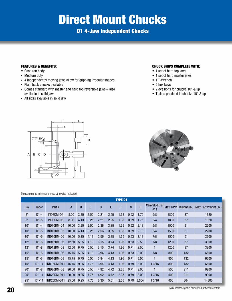
FEATURES & BENEFITS:• Cast iron body • Medium duty• 4 independently moving jaws allow for gripping irregular shapes• Plain back chucks available• Comes standard with master and hard top reversible jaws – also
available in solid jaw• All sizes available in solid jaw
CHUCK SHIPS COMPLETE WITH: • 1 set of hard top jaws • 1 set of hard master jaws • 1 T-Wrench • 2 hex keys • 2 eye bolts for chucks 10” & up• T-slots provided in chucks 10" & up
Direct Mount ChucksD1 4-Jaw Independent Chucks
Measurements in inches unless otherwise indicated.
TYPE D1
Dia. Taper Part # A B C D E F G H Cam Stud Dia. (in.) Max. RPM Weight (lb.) Max Part Weight (lb.)
8" D1-4 IND8DM-D4 8.00 3.25 2.50 2.21 2.95 1.38 0.52 1.75 5/8 1800 37 1320
8" D1-5 IND8DM-D5 8.00 4.13 3.25 2.21 2.95 1.38 0.59 1.75 3/4 1800 37 1320
10" D1-4 IND10DM-D4 10.00 3.25 2.50 2.36 3.35 1.35 0.52 2.13 5/8 1500 61 2200
10" D1-5 IND10DM-D5 10.00 4.13 3.25 2.56 3.35 1.35 0.59 2.13 3/4 1500 61 2200
10" D1-6 IND10DM-D6 10.00 5.25 4.19 2.56 3.35 1.35 0.63 2.13 7/8 1500 61 2200
12" D1-6 IND12DM-D6 12.50 5.25 4.19 3.15 3.74 1.96 0.63 2.50 7/8 1200 87 3300
12" D1-8 IND12DM-D8 12.50 6.75 5.50 3.15 3.74 1.96 0.71 2.50 1 1200 87 3300
15" D1-6 IND16DM-D6 15.75 5.25 4.19 3.94 4.13 1.96 0.63 3.00 7/8 800 132 6600
15" D1-8 IND16DM-D8 15.75 6.75 5.50 3.94 4.13 1.96 0.71 3.00 1 800 132 6600
15" D1-11 IND16DM-D11 15.75 9.25 7.75 3.94 4.13 1.96 0.79 3.00 1 3/16 800 132 6600
20" D1-8 IND20DM-D8 20.00 6.75 5.50 4.92 4.72 2.35 0.71 3.00 1 500 211 9900
20" D1-11 IND20DM-D11 20.00 9.25 7.75 4.92 4.72 2.35 0.79 3.00 1 3/16 500 211 9900
25" D1-11 IND25DM-D11 25.00 9.25 7.75 6.30 5.51 2.35 0.79 3.00w 1 3/16 400 364 14300
Max. Part Weight is calculated between centers.20

POWER CHUCKS• Tool Room Applications• Grinding• Odd-shaped Parts

FEATURES AND BENEFITS:•Highly flexible design solves gripping or turning issues in turn-key
applications• Unique top tooling• Compact and lightweight allowing for increased efficiency• Can be applied to mass produced metal working machines as
ordinary attachments•Most helpful for clamping non-standard and complicated parts for
finishing operation and fine finish cutting• Standard clamping jaw stroke is 0.7 to 3.0 mm• Also available in 2 or 4-Jaw models• 1 μm repeatability
CHUCK SHIPS COMPLETE WITH:• 1 set of soft top jaws•Wrench
Air Operated High Precision Power Chuck Rotating Model SPAC
Dimensions denoted in millimeters unless otherwise specified.
Other styles and special modifications available.
AIR CLAMPING ROTATING MODEL SPAC POWER CHUCK
Dia. A B C D E F No. Jaws Stroke Dia. Max RPM Grip Force Per Jaw 6 Bars
2" 64 53.7 50.00 20.6 9 42.40 3 2.0 mm 6000 60 kg/cm2
3" 80 70.0 60.00 20.7 18 55.30 3 2.5 mm 5800 120 kg/cm2
4" 100 88.9 82.55 20.7 18 55.45 3 2.5 mm 5000 210 kg/cm2
5" 125 114.3 101.60 20.7 18 55.45 3 2.5 mm 4300 330 kg/cm2
6" 150 135.8 125.00 20.7 18 55.45 3 2.5 mm 4000 350 kg/cm2
8" 200 183.0 167.60 20.7 6 80.45 3 2.5 mm 3500 900 kg/cm2
10" 250 233.7 215.80 20.7 6 80.45 3 2.5 mm 2500 900 kg/cm2
22

www.BuckChuckUSA.com1-800-228-BUCK
Air Operated Power ChucksModel TK 3-Jaw
OPTIONAL ACCESSORYAir Feed Tube
Also available in 2-Jaw.
FEATURES AND BENEFITS:• Pre-machined tapped holes for fixing jigs, making
additional machining unnecessary• Pre-machined lubrication path allows connection
to auto-lubrication unit• Built-in cylinder allows more stable gripping•Dowel pins built into master jaws allow for more
accurate and simplified remounting of soft jaws•Good coaxiality and repeatability allows for 1µm
accuracy, which simplifies machining process and increases efficiency
CHUCK SHIPS COMPLETE WITH:•One set of soft top jaws•Wrench
Measurements in inches unless otherwise indicated.
Model A B C D E D1 d(H7) D2
TK-04 20.75 12.7 12.7 101.6 30 82.55 18 25.0
TK-06 39.75 12.7 12.7 152.4 40 124.97 26 34.5
TK-08 65.75 25.4 – 203.2 45 167.64 50 50.0
Model H h W M1 M2
TK-04 70.3 3.2 16 M5x0.8P(PCDø88.9) M5x0.8P
TK-06 70.3 3.2 22 M6x1P(PCDø135.89) M5x0.8P
TK-08 99.5 7.0 25 M10x1.5P(PCDø182.88) M10x1.5P
Model M3 T1 T2
TK-04 9-3.18 M5x0.8P(PCDø88.9) –
TK-06 9-3.18 M6x1P(PCDø135.99) M6x1P(PCDø110)
TK-08 6-6.36 M8x1.25P(PCDø182.88) M8x1.25P(PCDø150)
Model RepeatabilityGripping Force
At Air Pressure 100 psi(lb.)
Max. Speedrpm (min1)
Weight(lb.)
TK-04 0.001 683 4500 10
TK-06 0.001 1741 4500 22
TK-08 0.001 3196 4500 58
Model T3 R1 R2 R3 T.I.R.Jaw T.I.R.
Jaw StrokeDia. (mm)
TK-04 – 30º – – 0.001 3
TK-06 M6x1P(PCDø135.99) 30º 30º 45º 0.001 3
TK-08 M8x1.25P(PCDø182.88) 30º 30º 30º 0.001 3
23

Stationary Self Contained Closed CenterModel MO 3-Jaw Wedge Type Power Chuck
OPTIONAL ACCESSORIESPneumaticManual switch
Also available in 2-Jaw.
FEATURES AND BENEFITS:• Flange bottom allows chuck to be easily fixed on a
plate for quick changeovers • Built-in cylinder allows for better stability and
takes up less space, which allows for higher machining efficiency
• Chuck can be controlled by M-code for use in an auto loading system
•Master jaws with 1.5 mm X 60° pitch enables hard and soft jaw interchangeability with CNC lathe chucks, allowing reduction in cost of spare jaws
•Dust-proof and water-resistant structure increases chuck life and efficiency
CHUCK SHIPS COMPLETE WITH:•One set of soft top jaws•Wrench
Dimensions denoted in millimeters unless otherwise specified.
MO 3-JAW WEDGE TYPE POWER CHUCK
Model A B C D E F G H I J K
M0-04 155 115 – 15 77.5 103.5 26 49.5 14 10 23
M0-05 185 135 – 15 95 128 33 62 14 10 25
M0-06 224 169 25 16 118 158 40 73 20 12 31
M0-08 265 210 30 20 138 180 42 95 25 14 35
M0-10 315 254 52 23 150 196 46 110 30 16 40
M0-12 375 304 80 23 165 219 54 129 30 21 50
MO 3-JAW WEDGE TYPE POWER CHUCK
Model L M N O P Q R S
M0-04 13 9 (PCD 165) PT1/8 M8x1.25P – – 64 47
M0-05 13 10 (PCD 135) PT1/4 M8x1.25P M8x1.25P – 80 47
M0-06 18 11 (PCD 202) PT1/4 M10x1.5P M8x1.25P – 80 47
M0-08 18 11 (PCD 243) PT1/4 M10x1.5P M10x1.5P M10x1.5P 80 47
M0-10 18 13 (PCD 285) PT1/4 M12x1.75P M12x1.75P M12x1.75P 80 47
M0-12 18 17 (PCD 340) PT3/8 M16x2P M12x1.75P M12x1.75P 80 55
MO 3-JAW WEDGE TYPE POWER CHUCK
Model PistonArea (cm2)
PlungerStroke (mm)
Jaw StrokeDia. (mm)
Max. Gripping
Force (lb.)
Max. Hydr. Pressure
(psi)
Gripping Forceat Air Pressure
100 psi (lb.)
Gross Weight(lb.)
Gripping Range (mm)
M0-04 57 9 3.8 5291 213 2425 22 9-115
M0-05 74 10 5.4 7242 284 2866 25 12-135
M0-06 97 12 5.5 11111 284 4409 46 15-169
M0-08 156 16 7.4 17857 284 7275 81 20-210
M0-10 235 19 8.8 26918 284 10582 124 33-254
M0-12 292 23 10.6 31967 284 11243 154 40-304
24

www.BuckChuckUSA.com1-800-228-BUCK
High Speed Thru-Hole Draw Tube OperatedModel OP 3-Jaw Wedge Type Power Chuck - Direct OEM Replacement
MODEL 0P 3-JAW WEDGE TYPE POWER CHUCK
Model OMax.
OMin.
PMax.
PMin. Q R S T U V W X Y Thru-Hole
Dia.Plunger stroke
(mm)
OP-205 19.0 6.0 1.0 -9.0 25 10 20.0 2 M40x1.5P 12 31.5 62.0 – 33.0 10
OP-206 24.0 7.0 11.0 -1.0 31 12 19.0 2 M55x2P 20 37.0 73.0 – 45.0 12
OP-208 30.0 10.0 14.5 -1.5 35 14 20.5 2 M60x2P 30 39.0 95.0 104.8 52.0 16
OP-210 34.0 12.0 8.5 -10.5 40 16 25.0 2 M85x2P 40 43 110 133.4 75.0 19
OP-212 46.0 12.0 8.0 -15.0 50 21 28.0 2 M100x2P 50 51 129 – 91.0 23
OP-215 46.0 13.0 7.0 -16.0 62 22 42.5 5 M130x2P 48 66 165 171.4 117.5 23
OP-218 78.0 18.0 7.0 -16.0 62 22 42.5 5 M130x2P 48 66 165 171.4 120.0 23
MODEL 0P 3-JAW WEDGE TYPE POWER CHUCK
Model Jaw StrokeDia. (mm)
Max. Speed(rpm)
Gross Weight(lb.)
Max. Pull Force (lb.)
Max. Gripping Force (lb.)
Max. Hydr. Pressure (psi)
Gripping Range (mm)Min. Max.
OP-205 5.4 7000 13 3814 7870 412 10 135
OP-206 5.5 6000 28 4718 12588 398 13 169
OP-208 7.4 5000 48 7408 18430 370 13 210
OP-210 8.8 4200 74 9436 24273 384 30 254
OP-212 10.6 3300 122 12125 31702 384 35 304
OP-215 10.6 2500 235 15741 40234 348 35 381
OP-218 10.6 2000 250 15741 40234 348 40 450
MODEL 0P 3-JAW WEDGE TYPE POWER CHUCK
Model Nose ofSpindle A B C D E E1 F G H H1 I1 J K L M N
Max.N
Min.
OP-205 A2-4 135 60 110 63.51 20 – 4 96 82.6 PCD118 M8x1.25P 33 M10x1.5P 15 14 26.20 23.50
OP-206 A2-5 169 81 140 82.56 15 – 5 116 104.8 PCD145 M10x1.5P 45 M10x1.5P 16 20 32.35 29.60
OP-208 A2-6 (A
2-5) 210 91 170 106.98 17 23 5 150 133.4 PCD180 M10x1.5P 52 M12x1.75P 18 25 39.10 35.40
OP-210 A2-8 (A
2-6) 254 100 220 139.72 18 28 5 190 171.4 PCD225 M12x1.75P 75.0 M16x2P 19 30 51.5 47.1
OP-212 A2-8 (A
2-6) 304 110 220 139.72 18 – 6 190 171.4 PCD250 M12x1.75P 91.0 M16x2P 25 30 61.6 56.3
OP-215 A2-11 (A
2-8) 381 133 300 196.87 22 33 6 260 235.0 PCD324 M12x1.75P 117.5 M20x2.5P 28 43 82.3 77.0
OP-218 A2-11 (A
2-8) 450 133 300 196.87 22 33 6 260 235.0 PCD230 M12x1.75P 120.0 M20x2.5P 28 43 83.8 78.5
CHUCK SHIPS COMPLETE WITH: • ASA B5.9 Type A spindle adapter• 1 set of soft top jaws•Wrench
FEATURES & BENEFITS:•High-quality alloy steel body allows for higher speeds• Sharply increased dynamic gripping force greatly improves
work efficiency and safety• Interchangeable top tooling with 1.5 mm x 60° jaw serration pitch• Compact and lightweight, allowing for improved efficiency•Direct mounting to fit ASA B5.9 Type A spindle• Improved lubrication system for high accuracy and endurance•Heat-treated alloy steel for high durability
Available in larger diameters upon request. Also available in 2- and 4-jaw models. Contact our sales office for more information.
Dimensions denoted in millimeters unless otherwise specified.
25

High Speed Thru-Hole Draw Tube OperatedModel OPF 4-Jaw Wedge Type Power Chuck – Direct OEM Replacement
CHUCK SHIPS COMPLETE WITH: • ASA B5.9 Type A spindle adapter• 1 set of soft top jaws•Wrench
Dimensions denoted in millimeters unless otherwise specified.
MODEL 4-JAW WEDGE TYPE POWER CHUCK
Model Nose of Spindle A B C D E E1 F G H H1 I1 J K
OPF-206 A2-5 169 81 140 82.56 15 – 5 116 104.8 PCD145 M10x1.5P 45.0 M10x1.5P
OPF-208 A2-6 (A2-5) 210 91 170 106.98 17 23 5 150 133.4 PCD180 M10x1.5P 52.0 M12x1.75P
OPF-210 A2-8 (A2-6) 254 100 220 139.72 18 28 5 190 171.4 PCD225 M12x1.75P 75.0 M16x2P
OPF-212 A2-8 (A2-6) 304 110 220 139.72 18 - 6 190 171.4 PCD250 M12x1.75P 91.0 M16x2P
OPF-215 A2-11 (A2-8) 381 133 300 196.87 22 33 6 260 235.0 PCD324 M12x1.75P 117.5 M20x2.5P
MODEL 4-JAW WEDGE TYPE POWER CHUCK
Model L M NMax.
NMin.
OMax.
OMin.
PMax.
PMin. Q R S T U V W X Y
OPF-206 16 20 32.35 29.6 24.0 7.0 11.0 -1.0 31 12 19.0 2 M55x2.0P 20 37.0 73.0 –
OPF-208 18 25 39.10 35.4 30.0 10.0 14.5 -1.5 35 14 20.5 2 M60x2.0P 30 39.0 95.0 104.8
OPF-210 19 30 51.50 47.1 34.0 12.0 8.5 -10.5 40 16 25.0 2 M85x2P 40 43.0 110.0 133.4
OPF-212 25 30 61.60 56.3 46.0 12.0 8.0 -15.0 50 21 28.0 2 M100x2P 50 51.0 129.0 -
OPF-215 28 43 82.30 77.0 46.0 13.0 7.0 -16.0 62 22 42.5 5 M130x2P 48 66.0 165.0 171.4
MODEL 4-JAW WEDGE TYPE POWER CHUCK
Model Thru-HoleDia. (mm)
Plunger stroke(mm)
Jaw StrokeDia. (mm)
Max. Speed(rpm)
Gross Weight (lb.)
Max. Pull Force (lb.)
Max. Gripping Force (lb.)
Max. Hydr. Pressure (psi)
Gripping Range (mm)Min. Max.
OPF-206 45.0 12 5.5 4500 31 3593 9215 298 22 169
OPF-208 52.0 16 7.4 3600 54 5379 13249 270 25 210
OPF-210 75.0 19 8.8 3200 84 6966 17747 284 28 254
OPF-212 91.0 23 10.6 2500 134 8994 22928 284 25 304
OPF-215 117.5 23 10.6 1800 246 11904 29982 270 63 381
FEATURES AND BENEFITS:•High-quality alloy steel body allows for high speeds• Sharply increased dynamic gripping force greatly improves work
efficiency and safety• Interchangeable top tooling with 1.5 mm x 60° jaw serration pitch• Compact and lightweight, allowing for increased efficiency•Direct mounting to fit ASA B5.9 Type A spindle• Improved lubrication system for high accuracy and endurance•Heat-treated alloy steel for high durability
Note: Actuation Packages may be needed. Please contact our sales office for more information.
26

www.BuckChuckUSA.com1-800-228-BUCK
Note: Actuation Packages may be needed. Please contact our sales office for more information.
FEATURES AND BENEFITS:•High-quality alloy steel body allows for high speeds• Sharply increased dynamic gripping force greatly improves work
efficiency and safety• Interchangeable top tooling with 1.5 mm x 60° jaw serration pitch• Compact and lightweight, allowing for increased efficiency•Direct mounting to fit ASA B5.9 Type A spindle• Improved lubrication system for high-accuracy and endurance•Heat-treated alloy steel for high durability
High Speed Closed Center Power ChuckModel CL 3-Jaw Wedge Type - Direct OEM Replacement
Dimensions denoted in millimeters unless otherwise specified.
Available in larger sizes and two-jaw model. Please contact our sales office for more information.
CHUCK SHIPS COMPLETE WITH: •ASAB5.9TypeAspindleadapter•1setofsofttopjaws•Wrench
MODEL CL 3-JAW WEDGE TYPE POWER CHUCK
Model Nose of Spindle A B C D E E1 F G H J K L M Nmax Nmin
CL-05 A2-4 135 55 80 63.51 – – 7 – 100.0 – M8x1.5P 14 14 30.4 27.20
CL-06 A2-5 165 74 140 82.56 15 – 5 116 104.8 21 M10x1.5P 14 20 37.8 33.25
CL-08 A2-6 (A2-5) 210 85 170 106.38 17 23 5 150 133.4 25 M12x1.75P 18 25 46.3 41.90
CL-10 A2-8 (A2-6) 254 89 220 139.72 18 28 5 190 171.4 34 M16x2P 25 30 51.4 47.00
CL-12 A2-8 304 106 220 139.72 18 – 6 190 171.4 34 M16x2P 25 30 60.7 55.45
CL-15 A2-11 381 114 300 196.87 22 – 6 260 235.0 – M20x2.5P 32 43 77.5 69.50
CL-18 A2-11 450 114 300 196.87 22 – 6 260 235.0 – M20x2.5P 32 43 108.0 100.00
MODEL CL 3-JAW WEDGE TYPE POWER CHUCK
Model Omax Omin Pmax Pmin Q R S T U V W X Y
CL-05 17.00 7.00 9.0 -6.0 25 10 35 2 M12x1.75P 28 31 62 –
CL-06 18.00 7.50 101.5 81.5 31 12 36 4 M16x2P 34 39 73 –
CL-08 22.50 9.00 127.0 106.0 35 14 36 5 M20x2.5P 38 42 95 –
CL-10 37.50 10.50 158.0 133.0 40 16 36 5 M20x2.5P 45 46 110 104.8
CL-12 47.00 11.00 163.0 133.0 50 18.0 36 5 M20x2.5P 50 54 130 133.4
CL-15 50.25 23.25 104.0 69.0 62 25.5 55 2 M30x3.5P 60 63 165 –
CL-18 49.50 25.50 92.0 57.0 62 25.5 55 2 M30x3.5P 60 63 165 –
MODEL CL 3-JAW WEDGE TYPE POWER CHUCK
Model Plunger Stroke (mm)
Jaw Stroke Dia. (mm) Max RPM Max Pull
Force (lb.)Max Grip Force (lb.)
Max Hydr. Pressure (psi) Weight (lb.) Grip Range (mm)
Min. Max.
CL-05 15 6.4 5500 1764 5401 312 13 8 135
CL-06 20 8.5 5000 3813 11464 384 25 18 165
CL-08 21 8.8 4600 5379 16402 355 48 12 210
CL-10 25 8.8 4000 6283 23831 412 74 16 254
CL-12 30 10.5 3200 8994 34171 412 129 18 304
CL-15 35 16.0 2800 18210 55754 462 222 68 381
CL-18 25 16.0 2500 18210 55754 462 250 85 450
27

Super Life Power Chuck The Original Buck Power Chuck – Stationary Hydraulic/Pneumatic
FEATURES AND BENEFITS:• Stationary hydraulic/pneumatic built-in cylinder uses less
space, while increasing stability and machining efficiency• Ideal for CNC machining centers as well as standard mills
and grinders•Designed with a sealed face to help protect internal
parts from abrasion for a longer service life in the most demanding applications
•Guaranteed repeatability of .001” TIR or better on duplicate part production
•Wear plates under master jaws are easily shimmed or replaced to restore original accuracy
NOTES:• Featured with American Square Serrated Master Jaws
(other jaw styles available)• Available with or without a Thru-Hole; available in 2-Jaw,
3-Jaw or 2/3-Jaw styles• Also available in a lightweight aluminum body• Parts available for previous models – contact our sales
office for more information•Made in the USA
Measurements in inches unless otherwise indicated.
STATIONARY HYDRAULIC/PNEUMATIC 3-JAW POWER CHUCK
Model A B C D E F G H Jaw Travel Max Drawbar Pull (lb.)
Max Line Pressure (psi)
A5606 6.50 2.00 1.00 0.25 2.88 0.41 5.19 0.16 0.25 2800 166
A5608 8.25 2.00 1.50 0.22 3.72 0.34 5.78 0.16 0.25 5000 170
A5610 10.00 2.00 2.00 0.31 4.50 0.53 6.37 0.31 0.25 9000 195
A5612 12.00 2.00 2.00 0.31 5.38 0.53 6.25 0.19 0.25 10500 160
A5615 15.00 2.00 3.18 0.31 6.75 0.66 8.06 0.38 0.25 15000 160
A5618 18.00 2.00 3.18 0.31 8.00 0.66 8.06 0.38 0.25 15000 105
A5624 24.00 2.00 3.75 0.50 9.38 0.78 9.50 0.31 0.25 15000 50
28

www.BuckChuckUSA.com1-800-228-BUCK
FEATURES AND BENEFITS:•Ajust-Tru® Precision! Dead-zero precision mounting feature for “near-zero” runout•Widekeywaytoincreasebearingsurfaces,lessenwearandincreasestability•Hardenedandgroundsteelwearsurfacesincreaseservicelife•Guaranteedrepeatabilityof.001”TIRorbetteronduplicatepartproduction•Wearplatesundermasterjawsareeasilyshimmedorreplacedtorestore original accuracy•Hardenedreplaceablewedgebushingsavailableforfactoryorfield replacement; simple grinding restores wedge to original fit•4-to-1mechanicaladvantageinallchucksizes
Super Life Power Chuck The Original Buck Power Chuck – Hydraulic Sliding Jaw
A BC
D
E
F
G
H
J
KL
M
N
ONOTES:•Featuredwithtongue&groovemasterjaws Other jaw styles available•AvailablewithorwithoutaThruHole•Availablein2-Jaw,3-Jawor2/3-Jawstyles •Alsoavailableinlightweightaluminumbody•Partsavailableforpreviousmodels–please contact our sales office for more information•Ajust-Tru® power chuck mounting plate required•MadeintheUSA
Measurements in inches unless otherwise indicated.
SUPER LIFE 3-JAW MODEL POWER CHUCK
Model A B C D E F G H J K L M (max) M (min) N O
A4006 6.50 4.78 1.00 0.63 2.06 0.47 3.25 5/8"-18 0.50 0.16 7/16"-14 2.44 2.19 0.13 1.50
A4008 8.25 6.16 1.50 0.66 2.63 0.53 3.86 5/8"-18 0.50 0.16 1/2"-13 3.06 2.75 0.13 1.75
A4010 10.00 7.91 2.00 0.88 3.38 0.69 4.47 1"-14 0.75 0.19 5/8"-11 3.81 3.44 0.13 2.13
A4012 12.00 7.91 2.00 0.88 3.38 0.69 4.47 1"-14 0.75 0.19 5/8"-11 4.50 4.13 0.13 2.50
A4015 15.00 11.78 3.19 0.94 4.63 0.78 5.16 1"-14 0.75 0.28 3/4"-10 5.63 5.25 0.13 3.00
A4018 18.00 11.78 3.19 0.94 4.63 0.78 5.16 1"-14 0.75 0.28 3/4"-10 5.63 5.25 0.13 3.00
A4021 21.00 16.03 3.75 1.19 6.50 0.94 6.50 1"-14 0.75 0.31 3/4"-10 7.13 6.63 0.13 3.00
A4024 24.00 16.03 3.75 1.19 6.50 0.94 6.50 1"-14 0.75 0.31 3/4"-10 7.13 6.63 0.13 3.00
SUPER LIFE 3-JAW MODEL POWER CHUCK
Model Jaw Travel Max Drawbar Force (lb.) Max RPM Wedge Travel (in.) Total Compensation Weight (lb.)
A4006 0.25 1900 2000 1.00 0.13 26
A4008 0.31 3300 1800 1.25 0.13 55
A4010 0.38 6000 1600 1.50 0.25 92
A4012 0.38 7000 1400 1.50 0.25 133
A4015 0.38 10000 1200 1.50 0.25 218
A4018 0.38 10000 1000 1.50 0.25 331
A4021 0.50 10000 900 2.00 0.25 570
A4024 0.50 10000 800 2.00 0.25 748
Note: Actuation Packages may be needed. Please contact our sales office for more information.
29

Super Life Power ChuckThe Original Buck Power Chuck – 2/3-Jaw Combination
NOTES:• Featured with tongue and groove master jaws;
other styles available• Available with or without a Thru Hole• 2-Jaw, 3-Jaw or 2/3-Jaw styles available• Parts available for previous models; contact our
sales office for more information• Also available in lightweight aluminum body• Ajust-Tru® power chuck mounting plate required•Made in the USA
A BC
D
E
F
G
H
J
KL
M
N
O
FEATURES AND BENEFITS:• Ajust-Tru® Precision! Dead-zero precision mounting features for “near-zero” runout•Holds both round and square parts for greater flexibility and less machine down time• Extended master jaws bear against front plate to virtually eliminate “bell mouthing”•Wide keyways to increase bearing surfaces, lessen wear and increase stability• Extremely rugged and precise – designed for easy maintenance•Hardened and ground steel wear surfaces increase service life•Guaranteed repeatability of .001” TIR or better on duplicate part production•Wear plates under master jaws are easily shimmed or replaced to restore original accuracy•Hardened replaceable wedge bushings available for factory or field replacement; simple
grinding restores wedge to original fit• 4 to 1 mechanical advantage
SUPER LIFE 2/3-JAW COMBINATION POWER CHUCK
Model A B C D E F G H J K L M (max) M (min) N O
A4610 10 7.91 2.00 0.88 3.38 0.69 4.47 1"-14 0.75 0.19 5/8"-11 3.81 3.44 0.13 2.13
A4612 12 7.91 2.00 0.88 3.38 0.69 4.47 1"-14 0.75 0.19 5/8"-11 4.50 4.13 0.13 2.50
A4615 15 11.78 3.19 0.94 4.63 0.78 5.16 1"-14 0.75 0.28 3/4"-10 5.63 5.25 0.13 3.00
A4618 18 11.78 3.19 0.94 4.63 0.78 5.16 1"-14 0.75 0.28 3/4"-10 5.63 5.25 0.13 3.00
A4621 21 16.03 3.75 1.19 6.50 0.94 6.50 1"-14 0.75 0.31 3/4"-10 7.13 6.63 0.13 3.00
A4624 24 16.03 3.75 1.19 6.50 0.94 6.50 1"-14 0.75 0.31 3/4"-10 7.13 6.63 0.13 3.00
SUPER LIFE 2/3-JAW COMBINATION POWER CHUCK
Model Jaw Travel Max Drawbar Force (kg) Wedge Travel Max RPM Weight (lb.)
A4610 0.38 9000 1.5 2600 92
A4612 0.38 10500 1.5 2200 133
A4615 0.38 15000 1.5 1500 218
A4618 0.38 15000 1.5 1200 331
A4621 0.50 15000 2.0 1000 570
A4624 0.50 15000 2.0 900 748
Measurements in inches unless otherwise indicated.
Note: Actuation Packages may be needed. Please contact our sales office for more information.
30

www.BuckChuckUSA.com1-800-228-BUCK
B
A
D
C
E
F
G
HJ
K
L
MN
QP
S Max.
O
Buck Pull-Back Power Chuck
Measurements in inches unless otherwise indicated.
3-JAW PULL-BACK POWER CHUCK
Part # Q R S MAX Jaw Travel (in.)
Wedge Travel (in.)
Max. Drawbar Force (kg) Max. RPM Weight (lb.)
3706 .437"-14 1 2.44 0.25 1.13 6000 3000 26
3708 .750"-16 1 3.06 0.28 1.28 10000 2500 55
3710 .875"-14 1 3.81 0.38 1.69 15000 2000 92
3712 .875"-14 1 4.50 0.38 1.69 18000 1700 133
3715 1"-14 1 5.63 0.38 1.69 25000 1400 218
3718 1"-14 2 5.63 0.38 1.69 25000 1100 331
3721 1"-14 2 7.13 0.50 2.28 25000 1080 570
3724 1"-14 3 7.13 0.50 2.28 25000 900 748
3-JAW PULL-BACK POWER CHUCK
Part # Chuck Size A B C D E F G H J K L M N O P
MINP
MAX
3706 6 6.50 4.78 0.75 0.63 2.06 0.469 3.06 .625"-18 1.25 2.25 1.13 1.50 0.50 0.31 0.31 0.16
3708 8 8.25 6.16 0.88 0.66 2.63 0.530 3.75 .625"-18 1.75 2.53 1.28 1.75 0.50 – 0.31 0.16
3710 10 10.00 7.91 0.88 0.88 2.63 0.530 4.72 1"-14 2.66 3.69 1.69 2.13 0.75 – 0.34 0.16
3712 12 12.00 7.91 0.88 0.88 3.38 0.660 5.13 1"-14 2.66 3.69 1.69 2.50 0.75 – 0.38 0.19
3715 15 15.00 11.78 1.25 0.94 4.63 0.780 5.50 1"-14 2.25 3.19 1.69 3.00 0.75 – 0.58 0.38
3718 18 18.00 11.78 1.25 0.94 4.63 0.780 6.00 1"-14 1.50 2.69 1.69 3.00 0.75 – 0.58 0.31
3721 21 21.00 16.03 2.00 1.19 6.50 0.940 7.94 1"-14 1.75 4.00 2.28 3.00 0.75 – 0.58 0.31
3724 24 24.00 16.03 2.00 1.19 6.50 0.940 7.94 1"-14 1.75 4.00 2.28 3.00 0.75 – 0.58 0.31
FEATURES AND BENEFITS:• Ajust-Tru® Precision! Dead-zero precision mounting features for “near-zero” runout• 100% more gripping power than conventional chucks• Perfect match for single or multiple spindle machines making heavy cuts on precision work• Angular jaws on wider keyway plus heavy-duty wedge offer strength and rigidity for
maximizing gripping power from beginning to end of jaw travel• Provides positive end location of parts by holding work solidly against work stops
NOTES:• Also available in 2-Jaw• Parts available for previous models;
contact our sales office for more info• Ajust-Tru® power chuck mounting
plate required•Made in USA
Note: Actuation Packages may be needed. Please contact our sales office for more information.
31
Buck Forkardt Quick Change Chucks
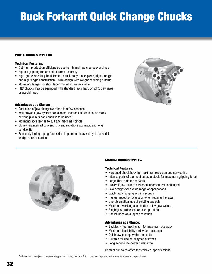
Available with base jaws, one-piece stepped hard jaws, special soft top jaws, hard top jaws, soft monoblock jaws and special jaws.
POWER CHUCKS TYPE FNC
Technical Features:•Optimumproductionefficienciesduetominimaljawchangeovertimes•Highestgrippingforcesandextremeaccuracy•High-grade,speciallyheat-treatedchuckbody–one-piece,highstrength and highly rigid construction – slim design with weight-reducing cutouts•Mountingflangesforshorttapermountingareavailable•FNCchucksmaybeequippedwithstandardjaws(hardorsoft),clawjaws or special jaws
Advantages at a Glance:•Reductionofjawchangeovertimetoafewseconds•WellprovenFjawsystemcanalsobeusedonFNCchucks,somany existing jaw sets can continue to be used•Mountingaccessoriestosuitanymachinespindle•Closelymaintainedconcentricityandrepetitiveaccuracy,andlong service life•Extremelyhighgrippingforcesduetopatentedheavy-duty,trapezoidal wedge hook actuation
MANUAL CHUCKS TYPE F+
Technical Features:•Hardenedchuckbodyformaximumprecisionandservicelife•Internalpartsofthemostsuitablesteelsformaximumgrippingforce•LargeThru-Holeforbarwork•ProvenFjawsystemhasbeenincorporatedunchanged•Jawdesignsforawiderangeofapplications•Quickjawchangingwithinseconds•Highestrepetitionprecisionwhenreusingthejaws•Unproblematicaluseofexistingjawsets•Maximumworkingspeedsduetolowjawweight•Singlejawprotectionforsaleoperation•Canbeusedonalltypesoflathes
Advantages at a Glance:•Backlash-freemechanismformaximumaccuracy•Maximumloadabilityandwearresistance•Quickjawchangewithinseconds•Suitableforuseonalltypesoflathes•Longservicelife(5-yearwarranty)
Contact our sales office for technical specifications.
32

TORK-LOK• Finish Turning• Grinding
34
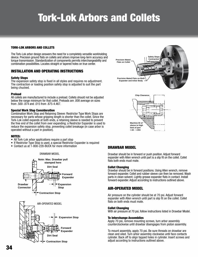
Precision Mated Flats on BothExpander and Arbor Body
Precision Mated Flats on Collet
Safety StopsContractionExpansion
Tork-Lok Arbors and Collets
TORK-LOK ARBORS AND COLLETS
The Tork-Lok arbor design answers the need for a completely versatile workholding device. Precision ground flats on collets and arbors improve long-term accuracy and torque transmission. Standardization of components permits interchangeability and combination possibilities. Locates straight or tapered holes on true center.
INSTALLATION AND OPERATING INSTRUCTIONS
Safety StopsThe expansion safety stop is fixed in all styles and requires no adjustment. The contraction or loading position safety stop is adjusted to suit the part being chucked.
PreloadAll collets are manufactured to include a preload. Collets should not be adjusted below the range minimum for that collet. Preloads are .008 average on sizes from .500-.874 and .015 from .875-4.467.
Special Work Stop ConsiderationCombination Work Stop and Retaining Sleeve: Restrictor Type Work Stops are necessary for parts whose gripping length is shorter than the collet. Since the Tork-Lok collet expands at both ends, a retaining sleeve is needed to prevent the free end of the collet from over expanding; a Restrictor Expander is used to reduce the expansion safety stop, preventing collet breakage (in case arbor is operated without a part in position).
NOTES: • All Tork-Lok arbor applications require a part stop• If Restrictor Type Stop is used, a special Restrictor Expander is required• Contact us at 1-800-228-BUCK for more information DRAWBAR MODEL
Drawbar should be in forward or push position. Adjust forward expander with Allen wrench until part is a slip fit on the collet. Collet flats both ends must mate.
Collet ChangingDrawbar should be in forward positions. Using Allen wrench, remove forward expander. Collet and rubber sleeve can then be removed. Wash parts in clean solvent. Lightly grease expander flats in contact. Install forward expander. Adjust according to instructions outlined above.
AIR-OPERATED MODEL
Air pressure on the cylinder should be at 70 psi. Adjust forward expander with Allen wrench until part is slip fit on the collet. Collet flats on both ends must mate.
Collet ChangingWith air pressure at 70 psi, follow instructions listed in Drawbar Model.
To Interchange AssembliesApply 70 psi, remove mounting screws, turn arbor assembly counterclockwise until drawbar disengages from piston assembly.
To mount assembly, apply 70 psi. Be sure threads on drawbar are clean and oiled. Turn arbor assembly clockwise until face contacts cylinder. Back off to align tapped holes in cylinder. Insert screws and adjust according to instructions outlined above.
Expansion Stop
ForwardExpander
Dirt Seal
Contraction Stop
Drawbar Connector
ForwardExpander
Expansion Stop
Contraction Stop
Note: Max. Drawbar pullstamped here
Dirt Seal
Chip Clearance
Machine ID ofsleeve to highlimit of part+.02 - +.004
AIR-OPERATED MODEL
DRAWBAR MODEL

www.BuckChuckUSA.com1-800-228-BUCK 35
TYPICAL APPLICATIONS FOR ARBORS
PISTON
DIFF. CARRIER
TRACK ROTOR
BALL JOINT
GEAR BLANK
PUMP HOUSING
COMPRESSION PLATE
FRONT BRAKE DRUM
Special arbor combinations are available upon request. Please contact us at 1-800-228-BUCK for more information.
Arbor Applications

36
Tork-Lok Drawbar ModelsLong Series Arbors
FEATURES AND BENEFITS:• Answers your need for versatility• Precision-ground flats improve accuracy• Standardization permits interchangeability• Locates straight or tapered holes on true center• Requires a part stop
SHIPS COMPLETE WITH:• Flange body• Connector• Expander• Collet sold separately; see pages 40 & 41
Part # Range A B C D E F G H J-J1 K L M
AC 2110 .500-.65510 Collets 2.49 0.88 0.39 0.66 0.50 0.4702
0.4692 1.25 3.37553.3750
0.7500.562 3/8 – 24 For (4) 3/8 S.H.S
on 2.50 B.C.For (4) 5/16 – 24
on 2.375 BCAC 2210 .593-.78012 Collets 2.69 1.06 0.41 0.66 0.50 0.5796
0.5786 1.25 3.37553.3750
0.7500.562 3/8 – 24 For (4) 3/8 S.H.S
on 2.50 B.C.
AC 2310 .718-.99918 Collets 2.96 1.25 0.49 0.66 0.50 0.7046
0.7036 1.25 3.37553.3750
0.750 0.562 3/8 – 24 For (4) 3/8 S.H.S
on 2.50 B.C.
AC 2410 .875-1.24912 Collets 3.58 1.44 0.56 0.90 0.56 0.8452
0.8442 1.75 4.12554.1250
1.2200.750 1/2 – 20 For (4) 1/2 S.H.S
on 3.12 B.C. For (4) 3/8 – 24on 2.875 BC
AC 2510 1.125-1.62416 Collets 3.89 1.62 0.69 0.90 0.56 1.0796
1.0786 1.75 4.12554.1250
1.2200.750 1/2 – 20 For (4) 1/2 S.H.S
on 3.12 B.C.
AC 2610 1.468-2.09220 Collets 4.14 1.81 0.82 0.72 0.68 1.4077
1.4067 2.50 4.87554.8750
1.5900.968 3/4 – 16 For (4) 1/2 S.H.S
on 3.75 B.C.
For (4) 3/8 – 24on 3.625 BC
AC 2710 1.937-2.84329 Collets 4.46 2.00 1.00 0.66 0.68 1.8452
1.8442 2.50 4.87554.8750
1.5900.968 3/4 – 16 For (4) 1/2 S.H.S
on 3.75 B.C.
AC 2810 2.563-3.59333 Collets 4.83 2.25 1.12 0.66 0.68 2.4390
2.4385 3.00 5.50055.5000
1.5900.968 3/4 – 16 For (4) 1/2 S.H.S
on 4.50 B.C.
AC 2910 3.312-4.46737 Collets 4.97 2.50 1.11 0.56 0.68 3.1885
3.1880 3.62 5.50055.5000
1.5900.068 3/4 – 16 For (4) 1/2 S.H.S
on 4.50 B.C.
LONG SERIES Measurements in inches unless otherwise indicated.

www.BuckChuckUSA.com1-800-228-BUCK 37
FEATURES AND BENEFITS:• Bolt circle has versatile three-bolt pattern• Tighter tolerance on size and parallelism for
locator mounting• Provisions for air sensing• Precision-ground flats improve accuracy• Standardization permits interchangeability• Locates straight or tapered holes on true center• Requires a part stop
Tork-Lok Metric Drawbar ModelsLong Series Arbors
Part # Q R
AC-2110M 15.00 M10 X 1.5P X 30.0 LG
AC-2210M 15.00 M10 X 1.5P X 30.0 LG
AC-2310M 15.00 M10 X 1.5P X 30.0 LG
AC-2410M 25.00 M12 X 1.75P X 50.0 LG
AC-2510M 25.00 M12 X 1.75P X 50.0 LG
AC-2610M 25.00 M16 X 2.0P X 50.0 LG
AC-2710M 25.00 M16 X 2.0P X 50.0 LG
AC-2810M 25.00 M16 X 2.0P X 50.0 LG
AC-2910M 25.00 M16 X 2.0P X 50.0 LG
Part # RANGE A B C D E F G H J-J1 K L M P
AC-2110M 12.70 - 16.64
10 Collets 63.30 22.40 9.92 10.30 19.08 11.91 31.74
85.74 85.73
18.26 14.27
M10 X 1.5P For (3)
M10 X 1.5P SHCS ON 63.50 BC
For (3) M8 X 1.25P SHCS ON 60.33 BC
12.68
AC-2210M 15.06 -19.81
12 Collets 68.40 26.90 10.52 10.30 19.08 15.47 31.74
85.74 85.73
18.26 14.27
M10X1.5P 12.68
AC-2310M 18.24 - 25.38
18 Collets 75.30 31.80 12.42 10.30 19.08 18.26 31.74
85.74 85.73
18.26 14.27
M10 X 1.5P 12.68
AC-2410M 22.23 - 31.73
12 Collets 91.00 36.60 14.27 15.10 22.23 21.44 44.44
104.79 104.78
30.99 19.05
M12 X 1.75P For (3)
M12 X 1.75P SHCS ON 79.38 BC
For (3) M10 X 1.5P SHCS ON 73.03 BC
15.83
AC-2510M 28.58 - 41.25
16 Collets 98.70 41.10 17.47 15.10 22.23 27.79 44.44
104.79 104.78
30.99 19.05
M12 X 1.75P 15.83
AC-2610M 37.29 - 53.14
20 Collets 105.20 46.00 20.67 13.50 22.23 36.12 63.49
123.84 123.83
40.39 24.59
M16 X 2.0P 15.83
AC-2710M 49.20 - 72.21
29 Collets 113.20 50.80 25.47 11.90 22.23 47.22 63.49
123.84 123.83
40.39 24.59
M16 X 2.0P For (3)
M12 X 1.75P SHCS ON 95.25 BC
For (3) M10 X 1.5P SHCS ON 92.08 BC
15.83
AC-2810M 65.100 - 91.26
33 Collets 122.60 57.20 28.47 11.90 22.23 62.31 76.19
139.71 139.70
40.39 24.59
M16 X 2.0P 15.83
AC-2910M 84.13 - 113.46
37 Collets 126.30 63.50 27.87 9.50 22.23 80.98 92.06
139.71 139.70
40.39 24.59
M16 X 2.0P 15.83
LONG SERIES Dimensions denoted in millimeters unless otherwise specified.
SHIPS COMPLETE WITH:• Flange body• Connector• Expander• Collet sold separately; see
pages 40 & 41
- Optional assembly method with male thread

38
SHIPS COMPLETE WITH:• Flange body• Connector• Expander• Collet sold separately; see pages 40 & 41
FEATURES AND BENEFITS:• Answers your need for versatility• Precision-ground flats improve accuracy• Standardization permits interchangeability• Locates straight or tapered holes on true center• Requires a part stop
Tork-Lok Drawbar ModelsShort Series Arbors
Part # Range A B C D E F G H J-J1 K L M
AC 8100 .500-.65515 Collets 1.81 0.590 0.42 0.25 0.50 0.4702
0.4692 0.88 3.37553.3750
0.7810.562 3/8 – 24 For (4) 3/8 S.H.S
on 2.50 BCFor (4) 5/16 – 24
on 2.375 BCAC 8200 .593-.78720 Collets 1.97 0.720 0.45 0.25 0.50 0.5796
0.5786 1.00 3.37553.3750
0.7810.562 3/8 – 24 For (4) 3/8 S.H.S
on 2.50 B.C.
AC 8300 .718-1.00028 Collets 2.15 0.840 0.51 0.25 0.50 0.7046
0.7036 1.12 3.37553.3750
0.7810.562 3/8 – 24 For (4) 3/8 S.H.S
on 2.50 B.C.
AC 8400 .875-1.29920 Collets 2.35 0.940 0.59 0.18 0.56 0.8452
0.8442 1.38 4.12554.1250
1.2500.750 1/2 – 20 For (4) 1/2 S.H.S
on 3.12 B.C. For (4) 3/8 – 24on 2.875 BC
AC 8500 1.125-1.62424 Collets 2.59 1.125 0.65 0.18 0.56 1.0796
1.0786 1.56 4.12554.1250
1.2500.750 1/2 – 20 For (4) 1/2 S.H.S
on 3.12 B.C.
AC 8600 1.468-2.10430 Collets 2.93 1.220 0.83 0.12 0.68 1.4077
1.4067 1.88 4.87554.8750
1.6250.968 3/4 – 16 For (4) 1/2 S.H.S
on 3.75 B.C. For (4) 3/8 – 24on 3.625 BC
AC 8700 1.937-2.82142 Collets 2.98 1.310 0.79 0.12 0.68 1.8452
1.8442 2.38 4.87554.8750
1.6250.968 3/4 – 16 For (4) 1/2 S.H.S
on 3.75 B.C.
SHORT SERIES Measurements in inches unless otherwise indicated.

www.BuckChuckUSA.com1-800-228-BUCK 39
Tork-Lok Metric Drawbar ModelsShort Series Arbors
Part # Q R
AC-8100M 15.00 M10 X 1.5P X 30.0 LG
AC-8200M 15.00 M10 X 1.5P X 40.0 LG
AC-8300M 15.00 M10 X 1.5P X 30.0 LG
AC-8400M 21.00 M12 X 1.75P X 40.0 LG
AC-8500M 21.00 M12 X 1.75P X 40.0 LG
AC-8600M 25.00 M16 X 2.0P X 50.0 LG
AC-8700M 25.00 M16 X 2.0P X 50.0 LG
Part # RANGE A B C E F H J-J1 K L M P
AC-8100M 12.70 - 16.64
15 Collets 46.00 15.00 10.72 19.08
11.94
11.92
85.74
85.73
19.84
14.27 M10 X 1.5P
For (3)
M10 X 1.5P
SHCS ON
63.50 BC
For (3)
M8 X 1.25P
SHCS ON
60.33 BC
13.04
AC-8200M 15.06 - 20.24
20 Collets 50.10 18.30 11.42 19.08
14.72
14.71
85.74
85.73
19.84
14.27 M10X1.5P 13.04
AC-8300M 18.24 - 25.40
28 Collets 54.50 21.30 12.92 19.08
17.89
17.88
85.74
85.73
19.84
14.27 M10 X 1.5P 13.04
AC-8400M 22.23 - 33.00
20 Collets 59.60 23.90 15.02 19.08
21.46
21.45
104.79
104.78
31.80
19.05 M12 X 1.75P
For (3)
M12 X 1.75P
SHCS ON
79.38 BC
For (3)
M10 X 1.5P
SHCS ON
73.03 BC
13.04
AC-8500M 28.58 - 41.71
24 Collets 65.70 28.60 16.42 19.08
27.42
27.41
104.79
104.78
31.75
19.05 M12 X 1.75P 13.04
AC-8600M 37.29 - 53.44
30 Collets 74.30 31.00 22.62 19.08
35.75
35.74
123.84
123.83
41.28
24.59 M16 X 2.0P
For (3)
M12 X 1.75P
SHCS ON
95.25 BC
For (3)
M10 X 1.5P
SHCS ON
92.08 BC
13.04
AC-8700M 649.20 - 71.65
42 Collets 75.50 33.30 21.52 19.08
46.86
46.85
123.84
123.83
41.28
24.59 M16 X 2.0P 13.04
SHORT SERIES
FEATURES AND BENEFITS:• Bolt circle has versatile three-bolt pattern• Tighter tolerance on size and parallelism for
locator mounting• Provisions for air sensing• Precision-ground flats improve accuracy• Standardization permits interchangeability• Locates straight or tapered holes on true center• Requires a part stop
SHIPS COMPLETE WITH:• Flange body• Connector• Expander• Collet sold separately; see
pages 40 & 41
- Optional assembly method with male thread
Dimensions denoted in millimeters unless otherwise specified.
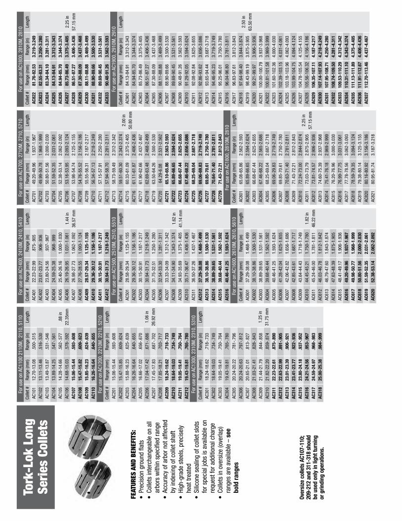
Tork
-Lok
Lon
g Se
ries
Col
lets
FEAT
URES
AND
BEN
EFIT
S:•
Prec
isio
n gr
ound
flat
s•
Colle
ts in
terc
hang
eabl
e on
all
arbo
rs w
ithin
spe
cifie
d ra
nge
•Ac
cura
cy o
f arb
or n
ot a
ffect
ed
by in
dexi
ng o
f col
let s
haft
•Hi
gh-g
rade
ste
els,
pre
cise
ly
heat
trea
ted
•Si
licon
e se
alin
g of
col
let s
lots
fo
r spe
cial
jobs
is a
vaila
ble
on
requ
est f
or a
dditi
onal
cha
rge
•Co
llets
in o
vers
ize
(ove
rlap)
ra
nges
are
ava
ilabl
e –
see
bold
rang
es
For u
se o
n AC
1100
211
0M,
2110
, 511
0Fo
r use
on
AC14
00, 2
410M
, 241
0, 5
410
For u
se o
n AC
1700
, 271
0M, 2
710,
571
0Fo
r use
on
AC18
00, 2
810M
, 281
0Co
llet #
Rang
e (m
m)
Rang
e (in
)Le
ngth
Colle
t #Ra
nge
(mm
)Ra
nge
(in)
Leng
thCo
llet #
Rang
e (m
m)
Rang
e (in
)Le
ngth
Colle
t #Ra
nge
(mm
)Ra
nge
(in)
Leng
th
AC10
112
.70-
13.0
8.5
00-.
515
.88
in22
.35m
m
AC40
122
.23-
22.9
9.8
75-.
905
1.44
in36
.57
mm
AC70
149
.20-
49.9
61.
937-
1.96
7
2.00
in50
.80
mm
AC82
281
.76-
82.5
33.
219-
3.24
9
2.25
in57
.15
mm
AC10
213
.11-
13.4
6.5
16-.
530
AC40
223
.01-
23.7
7.9
06-.
936
AC70
249
.99-
50.7
81.
968-
1.99
9AC
823
82.5
5-83
.31
3.25
0-3.
280
AC10
313
.49-
13.8
7.5
31-.
546
AC40
323
.80-
24.5
6.9
37-.
967
AC70
350
.80-
51.5
62.
000-
2.03
0AC
824
83.3
4-84
.10
3.28
1-3.
311
AC10
413
.89-
14.2
5.5
47-.
561
AC40
424
.59-
25.3
8.9
68-.
999
AC70
451
.59-
52.3
52.
031-
2.06
1AC
825
84.1
3-84
.91
3.31
2-3.
343
AC10
514
.28-
14.6
6.5
62-.
577
AC40
525
.40-
26.1
61.
000-
1.03
0AC
705
52.3
8-53
.14
2.06
2-2.
092
AC82
684
.94-
85.7
03.
344-
3.37
4AC
106
14.6
8-15
.03
.578
-.59
2AC
406
26.1
9-26
.95
1.03
1-1.
061
AC70
653
.16-
53.9
52.
093-
2.12
4AC
827
85.7
3-86
.49
3.37
5-3.
405
AC10
715
.06-
15.4
4.5
93-.
608
AC40
726
.98-
27.7
31.
062-
1.09
2AC
707
53.9
8-54
.74
2.12
5-2.
155
AC82
886
.51-
87.2
73.
406-
3.43
6AC
108
15.4
7-15
.82
.609
-.62
3AC
408
27.7
6-28
.55
1.09
3-1.
124
AC70
854
.76-
55.5
22.
156-
2.18
6AC
829
87.3
0-88
.09
3.43
7-3.
468
AC10
915
.85-
16.2
3.6
24-.
639
AC40
928
.57-
29.3
41.
125-
1.15
5AC
709
55.5
5-56
.31
2.18
7-2.
217
AC83
088
.11-
88.8
83.
469-
3.49
9AC
110
16.2
6-16
.64
.640
-.65
5AC
410
29.3
6-30
.12
1.15
6-1.
186
AC71
056
.34-
57.1
32.
218-
2.24
9AC
831
88.9
0-89
.66
3.50
0-3.
530
For u
se o
n AC
1200
, 221
0M, 2
210,
521
0AC
411
30.1
5-30
.91
1.18
7-1.
217
AC71
157
.15-
57.9
12.
250-
2.28
0AC
832
89.6
9-90
.45
3.53
1-3.
561
Colle
t #Ra
nge
(mm
)Ra
nge
(in)
Leng
thAC
412
30.9
4-31
.73
1.21
8-1.
249
AC71
257
.94-
58.7
02.
281-
2.31
1AC
833
90.4
8-91
.26
3.56
2-3.
593
AC20
115
.06-
15.4
4.5
93-.
608
1.06
in26
.92
mm
For u
se o
n AC
1500
, 251
0M, 2
510,
551
0AC
713
58.7
3-59
.49
2.31
2-2.
342
For u
se o
n AC
1900
, 291
0M, 2
910
AC20
215
.47-
15.8
5.6
09-.
624
Colle
t #Ra
nge
(mm
)Ra
nge
(in)
Leng
thAC
714
59.5
1-60
.30
2.34
3-2.
374
Colle
t #Ra
nge
(mm
)Ra
nge
(in)
Leng
th
AC20
315
.88-
16.2
3.6
25-.
639
AC50
128
.58-
29.3
41.
125-
1.15
5
1.62
in41
.14
mm
AC71
560
.33-
61.0
92.
375-
2.40
5AC
901
84.1
3-84
.91
3.31
2-3.
343
2.50
in63
.50
mm
AC20
416
.26-
16.6
4.6
40-.
655
AC50
229
.36-
30.1
21.
156-
1.18
6AC
716
61.1
1-61
.87
2.40
6-2.
436
AC90
284
.94-
85.7
03.
344-
3.37
4
AC20
516
.66-
17.0
2.6
56-.
670
AC50
330
.15-
30.9
11.
187-
1.21
7AC
717
61.9
0-62
.66
2.43
7-2.
467
AC90
385
.73-
86.4
93.
375-
3.40
5
AC20
617
.04-
17.4
2.6
71-.
686
AC50
430
.94-
31.7
31.
218-
1.24
9AC
718
62.6
9-63
.48
2.46
8-2.
499
AC90
486
.51-
87.2
73.
406-
3.43
6
AC20
717
.45-
17.8
3.6
87-.
702
AC50
531
.75-
32.5
11.
250-
1.28
0AC
719
63.5
0-64
.26
2.50
0-2.
530
AC90
587
.30-
88.0
93.
437-
3.46
8
AC20
817
.85-
18.2
1.7
03-.
717
AC50
632
.54-
33.3
01.
281-
1.31
1AC
720
64.2
9-6.
082.
531-
2.56
2AC
906
88.1
1-88
.88
3.46
9-3.
499
AC20
918
.24-
19.6
2.7
18-.
733
AC50
733
.33-
34.0
91.
312-
1.34
2AC
721
65.1
0-65
.86
2.56
3-2.
593
AC90
788
.90-
89.6
63.
500-
3.53
0
AC21
018
.64-
19.0
3.7
34-.
749
AC50
834
.11-
34.9
01.
343-
1.37
4AC
722
65.8
9-66
.65
2.59
4-2.
624
AC90
889
.69-
90.4
53.
531-
3.56
1
AC21
119
.05-
19.4
1.7
50-.
764
AC50
934
.93-
35.6
91.
375-
1.40
5AC
723
66.6
8-67
.44
2.62
5-2.
655
AC90
990
.48-
91.2
63.
562-
3.59
3
AC21
219
.43-
19.8
1.7
65-.
780
AC51
035
.71-
36.4
71.
406-
1.43
6AC
724
67.4
6-68
.22
2.65
6-2.
686
AC91
091
.29-
92.0
53.
594-
3.62
4
For u
se o
n AC
1300
, 231
0M, 2
310,
531
0AC
511
36.5
0-37
.26
1.43
7-1.
467
AC72
568
.25-
69.0
42.
687-
2.71
8AC
911
92.0
8-92
.84
3.62
5-3.
655
Colle
t #Ra
nge
(mm
)Ra
nge
(in)
Leng
thAC
512
37.2
9-38
.08
1.46
8-1.
499
AC72
669
.06-
69.8
32.
719-
2.74
9AC
912
92.8
6-93
.62
3.65
6-3.
686
AC30
118
.24-
18.6
2.7
18-.
733
1.25
in31
.75
mm
AC51
338
.10-
38.8
61.
500-
1.53
0AC
727
69.8
5-70
.61
2.75
0-2.
780
AC91
393
.65-
94.4
43.
687-
3.71
8
AC30
218
.64-
19.0
3.7
34-.
749
AC51
438
.89-
39.6
51.
531-
1.56
1AC
728
70.6
4-71
.40
2.78
1-2.
811
AC91
494
.46-
95.2
33.
719-
3.74
9
AC30
319
.05-
19.4
1.7
50-.
764
AC51
539
.68-
40.4
41.
562-
1.59
2AC
729
71.4
3-72
.21
2.81
2-2.
843
AC91
595
.25-
96.0
13.
750-
3.78
0
AC30
419
.43-
19.8
1.7
65-.
780
AC51
640
.46-
41.2
51.
593-
1.62
4Fo
r use
on
AC18
00, 2
810M
, 281
0AC
916
96.0
4-96
.80
3.78
1-3.
811
AC30
520
.24-
20.2
2.7
81-.
796
For u
se o
n AC
1600
, 261
0M, 2
610,
561
0Co
llet #
Rang
e (m
m)
Rang
e (in
)Le
ngth
AC91
796
.83-
97.6
13.
812-
3.84
3
AC30
620
.24-
20.6
3.7
97-.
812
Colle
t #Ra
nge
(mm
)Ra
nge
(in)
Leng
thAC
801
65.0
8-65
.86
2.56
2-2.
593
2.25
in57
.15
mm
AC91
897
.64-
98.4
03.
844-
3.87
4
AC30
720
.65-
21.0
1.8
13-.
827
AC60
137
.29-
38.0
81.
468-
1.49
9
1.82
in46
.22
mm
AC80
265
.89-
66.6
52.
594-
2.62
4AC
919
98.4
3-99
.19
3.87
5-3.
905
AC30
821
.03-
21.4
1.8
28-.
843
AC60
238
.10-
38.8
61.
500-
1.53
0AC
803
66.6
8-67
.44
2.62
5-2.
655
AC92
099
.21-
99.9
73.
906-
3.93
6
AC30
921
.44-
21.7
9.8
44-.
858
AC60
338
.89-
39.6
51.
531-
1.56
1AC
804
67.4
6-68
.22
2.56
5-2.
686
AC92
110
0.00
-100
.79
3.93
7-3.
968
AC31
021
.82-
22.2
0.8
59-.
874
AC60
439
.68-
40.4
41.
562-
1.59
2AC
805
68.2
5-69
.04
2.68
7-2.
718
AC92
210
0.81
-101
.58
3.96
9-3.
999
AC31
122
.23-
22.6
1.8
75-.
890
AC60
540
.46-
41.2
51.
593-
1.62
4AC
806
69.0
6-29
.83
2.71
9-2.
749
AC92
310
1.60
-102
.36
4.00
0-4.
030
AC31
222
.63-
22.9
9.8
91-.
905
AC60
641
.28-
42.0
41.
625-
1.65
5AC
807
69.8
5-70
.61
2.75
0-2.
780
AC92
410
2.39
-103
.15
4.03
1-4.
061
AC31
323
.01-
23.3
9.9
06-.
921
AC60
742
.06-
42.8
21.
656-
1.68
6AC
808
70.6
3-71
.40
2.78
1-2.
811
AC92
510
3.18
-103
.96
4.06
2-4.
093
AC31
423
.41-
23.7
7.9
22-.
936
AC60
842
.85-
43.6
11.
687-
1.71
7AC
809
71.4
3-72
.21
2.81
2-2.
843
AC92
610
3.99
-104
.75
4.09
4-4.
124
AC31
523
.80-
24.1
8.9
37-.
952
AC60
943
.64-
44.4
31.
718-
1.74
9AC
810
72.2
4-73
.00
2.84
4-2.
874
AC92
710
4.78
-105
.54
4.12
5-4.
155
AC31
624
.21-
24.5
6.9
53-.
967
AC61
044
.45-
45.2
11.
750-
1.78
0AC
811
73.0
3-73
.79
2.87
5-2.
905
AC92
810
5.56
-106
.32
4.15
6-4.
186
AC31
724
.59-
24.9
7.9
68-.
983
AC61
145
.24-
46.0
01.
781-
1.81
1AC
812
73.8
1-74
.57
2.90
6-2.
936
AC92
910
6.35
-107
.11
4.18
7-4.
217
AC31
825
.00-
25.3
8.9
84-.
999
AC61
246
.03-
46.7
81.
812-
1.84
2AC
813
74.6
0-75
.39
2.93
7-2.
968
AC93
010
7.14
-107
.93
4.21
8-4.
249
AC61
346
.79-
47.6
01.
843-
1.87
4AC
814
75.4
1-76
.18
2.96
9-2.
999
AC93
110
7.95
-108
.71
4.25
0-4.
280
AC61
447
.63-
48.3
91.
875-
1.90
5AC
815
76.2
0-76
.96
3.00
0-3.
030
AC93
210
8.74
-109
.50
4.28
1-4.
311
AC61
548
.41-
49.1
71.
906-
1.93
6AC
816
76.9
9-77
.75
3.03
1-3.
061
AC93
310
9.53
-110
.29
4.31
2-4.
342
AC61
649
.20-
49.9
61.
937-
1.96
7AC
817
77.7
8-78
.56
3.06
2-3.
093
AC93
411
0.31
-111
.10
4.34
3-4.
374
AC61
749
.98-
50.7
71.
968-
1.99
9AC
818
78.5
9-79
.35
3.09
4-3.
124
AC93
511
1.13
-111
.89
4.37
5-4.
405
AC61
850
.80-
51.5
62.
000-
2.03
0AC
819
79.3
8-80
.14
3.12
5-3.
155
AC93
611
1.91
-112
.67
4.40
6-4.
436
AC61
951
.59-
52.3
52.
031-
2.06
1AC
820
80.1
6-80
.92
3.15
6-3.
186
AC93
711
2.70
-113
.46
4.43
7-4.
467
AC62
052
.38-
53.1
42.
062-
2.09
2AC
821
80.9
5-81
.74
3.18
7-3.
218
Over
size
col
lets
AC1
07-1
10;
209-
212
and
311-
318
shou
ldbe
use
d on
ly in
ligh
t tur
ning
or g
rindi
ng o
pera
tions
.

Tork
-Lok
Sho
rt
Seri
es C
olle
ts
FEAT
URES
AND
BEN
EFIT
S:•
Prec
isio
n gr
ound
flat
s•
Colle
ts in
terc
hang
eabl
e on
all
arbo
rs w
ithin
spe
cifie
d ra
nge
•Ac
cura
cy o
f arb
or n
ot a
ffect
ed
by in
dexi
ng o
f col
let s
haft
•Hi
gh-g
rade
ste
els,
pre
cise
ly
heat
trea
ted
•Si
licon
e se
alin
g of
col
let s
lots
fo
r spe
cial
jobs
is a
vaila
ble
on
requ
est f
or a
dditi
onal
cha
rge
•Co
llets
in o
vers
ize
(ove
rlap)
ra
nges
are
ava
ilabl
e –
see
bold
rang
es
For u
se o
n AC
7100
A, 8
100M
, 810
0, 1
2100
For u
se o
n AC
7300
A, 8
300,
830
0M, 1
2300
For u
se o
n AC
7500
A, 8
500,
850
0M, 1
2500
For u
se o
n AC
7600
A, 8
600,
860
0M, 1
2600
Colle
t #Ra
nge
(mm
)Ra
nge
(in)
Leng
thCo
llet #
Rang
e (m
m)
Rang
e (in
)Le
ngth
Colle
t #Ra
nge
(mm
)Ra
nge
(in)
Leng
thCo
llet #
Rang
e (m
m)
Rang
e (in
)Le
ngth
AC71
0112
.70-
12.9
5.5
00-.
510
.59
in14
.986
mm
AC73
1221
.03-
21.2
6.8
28-.
837
.84
in21
.34
mm
AC75
0128
.58-
29.1
11.
125-
1.14
6
1.12
5 in
28.5
8 m
m
AC76
2349
.20-
49.7
11.
937-
1.95
7
1.22
in30
.99
mm
AC71
0212
.98-
13.2
1.5
11-.
520
AC73
1321
.29-
21.5
1.8
38-.
847
AC75
0229
.13-
29.6
71.
147-
1.16
8AC
7624
49.7
3-50
.24
1.95
8-1.
978
AC71
0313
.23-
13.4
8.5
21-.
531
AC73
1421
.54-
21.7
4.8
48-.
856
AC75
0329
.69-
30.2
31.
169-
1.19
0AC
7625
50.2
7-50
.78
1.97
9-1.
999
AC71
0413
.51-
13.7
4.5
32-.
541
AC73
1521
.77-
22.0
0.8
57-.
866
AC75
0430
.25-
30.7
91.
191-
1.21
2AC
7626
50.8
0-51
.31
2.00
0-2.
020
AC71
0513
.77-
14.0
2.5
42-.
552
AC73
1622
.02-
22.1
2.8
67-.
874
AC75
0530
.81-
31.3
41.
213-
1.23
4AC
7627
51.3
3-51
.84
2.02
1-2.
041
AC71
0614
.05-
14.2
8.5
53-.
562
AC73
1722
.23-
22.2
5.8
75-.
884
AC75
0631
.37-
31.9
01.
235-
1.25
6AC
7628
51.8
7-52
.38
2.04
2-2.
062
AC71
0714
.30-
14.2
6.5
63-.
572
AC73
1822
.48-
22.7
3.8
85-.
895
AC75
0731
.93-
32.4
61.
257-
1.27
8AC
7629
52.4
0-52
.91
2.06
3-2.
083
AC71
0814
.55-
14.7
8.5
73-.
582
AC73
1922
.76-
22.9
9.8
96-.
905
AC75
0832
.49-
33.0
01.
279-
1.29
9AC
7630
52.9
3-53
.44
2.08
4-2.
104
AC71
0914
.81-
15.0
4.5
83-.
592
AC73
2023
.01-
23.2
7.9
06-.
916
AC75
0933
.02-
33.5
31.
300-
1.32
0Fo
r use
on
AC77
0A, 8
700,
870
0M, 1
2700
AC71
1015
.06-
15.3
2.5
93-.
603
AC73
2123
.29-
23.5
2.9
17-.
926
AC75
1033
.55-
34.0
61.
321-
1.34
1Co
llet #
Rang
e (m
m)
Rang
e (in
)Le
ngth
AC71
1115
.34-
15.5
7.6
04-.
613
AC73
2223
.55-
23.8
0.9
27-.
937
AC75
1134
.09-
34.6
01.
342-
1.36
2AC
7701
49.2
0-49
.71
1.93
7-1.
957
1.31
in33
.27
mm
AC71
1215
.60-
15.8
5.6
14-.
624
AC73
2323
.83-
24.0
5.9
38-.
947
AC75
1234
.62-
35.1
31.
363-
1.38
3AC
7702
49.7
3350
.24
1.95
8-1.
978
AC71
1315
.88-
16.1
0.6
25-.
634
AC73
2424
.08-
24.3
3.9
48-.
958
AC75
1335
.15-
35.6
61.
384-
1.40
4AC
7703
50.2
7-50
.77
1.97
9-1.
999
AC71
1416
.13-
16.3
8.6
35-.
645
AC73
2524
.36-
24.5
9.9
59-.
968
AC75
1435
.69-
36.2
01.
405-
1.42
5AC
7704
50.8
0-51
.31
2.00
0-2.
020
AC71
1516
.41-
16.6
4.6
46-.
655
AC73
2624
.61-
24.8
7.9
69-.
979
AC75
1536
.22-
36.7
31.
426-
1.44
6AC
7705
51.3
3-51
.84
2.02
1-2.
041
For u
se o
n AC
7200
A, 8
200M
, 820
0, 1
2200
AC73
2724
.89-
25.1
2.9
80-.
989
AC75
1636
.75-
37.2
61.
447-
1.46
7AC
7706
51.8
7-52
.38
2.04
2-2.
062
Colle
t #Ra
nge
(mm
)Ra
nge
(in)
Leng
thAC
7328
25.1
5-25
.40
.990
-1.0
00AC
7517
37.2
9-37
.82
1.46
8-1.
489
AC77
0752
.40-
52.9
12.
063-
2.08
3
AC72
0115
.06-
15.3
1.5
93-.
603
.72
in18
.29
mm
For u
se o
n AC
7400
A, 8
400,
840
0M, 1
2400
AC75
1837
.85-
38.3
81.
490-
1.51
1AC
7708
52.9
3-53
.44
2.08
4-2.
104
AC72
0215
.34-
15.5
7.6
04-.
613
Colle
t #Ra
nge
(mm
)Ra
nge
(in)
Leng
thAC
7519
38.4
1-38
.94
1.51
2-1.
533
AC77
0953
.47-
53.9
82.
105-
2.12
5
AC72
0315
.60-
15.8
5.6
14-.
624
AC74
0122
.26-
22.5
9.8
75-.
895
.94
in23
.88
mm
AC75
2038
.96-
39.5
01.
534-
1.55
5AC
7710
54.0
0-54
.51
2.12
6-2.
146
AC72
0415
.88-
16.1
0.6
25-.
634
AC74
0222
.76-
23.2
7.8
96-.
916
AC75
2139
.52-
40.0
61.
556-
1.57
7AC
7711
54.5
3-55
.04
2.14
7-2.
167
AC72
0516
.13-
16.3
8.6
35-.
645
AC74
0323
.29-
23.8
0.9
17-.
937
AC75
2240
.08-
40.6
21.
578-
1.59
9AC
7712
55.0
7-55
.58
2.16
8-2.
188
AC72
0616
.41-
16.6
4.6
46-.
655
AC74
0423
.83-
24.3
3.9
38-.
958
AC75
2340
.64-
117.
371.
600-
1.62
1AC
7713
55.6
0-56
.11
2.18
9-2.
209
AC72
0716
.66-
16.9
2.6
56-.
666
AC74
0524
.36-
24.8
7.9
59-.
979
AC75
2441
.20-
41.7
11.
622-
1.64
2AC
7714
56.1
3-56
.64
2.21
0-2.
230
AC72
0816
.94-
17.1
7.6
67-.
676
AC74
0624
.89-
25.4
0.9
80-1
.000
For u
se o
n AC
7600
A, 8
600,
860
0M, 1
2600
AC77
1556
.67-
57.1
82.
231-
2.25
1
AC72
0917
.20-
17.4
5.6
77-.
687
AC74
0725
.43-
25.9
31.
001-
1.02
1Co
llet #
Rang
e (m
m)
Rang
e (in
)Le
ngth
AC77
1657
.20-
57.7
12.
252-
2.27
2
AC72
1017
.48-
17.7
0.6
88-.
697
AC74
0825
.96-
26.4
71.
022-
1.04
2AC
7601
37.2
9-37
.82
1.46
8-1.
489
1.22
in30
.99
mm
AC77
1757
.73-
58.2
42.
273-
2.29
3
AC72
1117
.73-
17.9
6.6
98-.
707
AC74
0926
.49-
27.0
01.
043-
1.06
3AC
7602
37.8
5-38
.38
1.49
0-1.
511
AC77
1858
.27-
58.7
82.
294-
2.31
4
AC72
1217
.98-
18.2
1.7
08-.
717
AC74
1027
.02-
27.5
31.
064-
1.08
4AC
7603
38.4
1-38
.94
1.51
2-1.
533
AC77
1958
.80-
59.3
12.
315-
2.33
5
AC72
1318
.24-
18.4
7.7
18-.
727
AC74
1127
.56-
28.0
41.
105-
1.12
4AC
7604
38.9
6-39
.50
1.53
4-1.
555
AC77
2059
.33-
59.8
42.
336-
2.35
6
AC72
1418
.49-
18.7
2.7
28-.
737
AC74
1328
.58-
29.1
11.
125-
1.14
6AC
7605
39.5
2-40
.06
1.55
6-1.
577
AC77
2159
.81-
60.3
82.
357-
2.37
7
AC72
1518
.75-
18.9
7.7
38-.
747
AC74
1429
.13-
29.6
71.
147-
1.16
8AC
7606
40.0
8-40
.61
1.57
8-1.
599
AC77
2260
.40-
60.9
12.
378-
2.39
8
AC72
1619
.00-
19.2
3.7
48-.
757
AC74
1529
.69-
30.2
71.
169-
1.19
0AC
7607
40.6
4-41
.17
1.60
0-1.
621
AC77
2360
.94-
61.4
42.
399-
2.41
9
AC72
1719
.25-
19.4
8.7
58-.
767
AC74
1630
.25-
30.7
91.
191-
1.21
2AC
7608
41.2
0-41
.71
1.62
2-1.
642
AC77
2461
.47-
61.9
72.
420-
2.44
0
AC72
1819
.51-
19.7
4.7
68-.
777
AC74
1730
.81-
31.3
41.
213-
1.23
4AC
7609
41.7
3-42
.24
1.64
3-1.
663
AC77
2562
.00-
62.5
12.
441-
2.46
1
AC72
1919
.76-
19.9
9.7
78-.
787
AC74
1831
.37-
31.9
01.
235-
1.25
6AC
7610
42.2
7-42
.77
1.66
4-1.
684
AC77
2662
.54-
63.0
22.
462-
2.48
1
AC72
2020
.06-
20.2
4.7
88-.
797
AC74
1931
.93-
32.4
61.
257-
1.27
8AC
7611
42.8
0-43
.31
1.68
5-1.
705
AC77
2763
.04-
63.5
32.
482-
2.50
1
For u
se o
n AC
7300
A, 8
300,
830
0M, 1
2300
AC74
2032
.49-
33.0
01.
279-
1.29
9AC
7612
43.3
3-43
.84
1.70
6-1.
726
AC77
2863
.55-
64.0
32.
502-
2.52
1
Colle
t #Ra
nge
(mm
)Ra
nge
(in)
Leng
thAC
7613
43.8
7-44
.37
1.72
7-1.
747
AC77
2964
.06-
64.5
42.
522-
2.54
1
AC73
0118
.24-
18.4
7.7
18-.
727
.84
in21
.34
mm
AC76
1444
.40-
44.9
11.
748-
1.76
8AC
7730
64.5
7-65
.05
2.54
2-2.
561
AC73
0218
.49-
18.7
2.7
28-.
737
AC76
1544
.93-
45.4
41.
769-
1.78
9AC
7731
65.0
8-65
.61
2.56
2-2.
583
AC73
0318
.75-
18.9
7.7
38-.
747
AC76
1645
.47-
45.9
71.
790-
1.81
0AC
7732
65.6
3-66
.14
2.58
4-2.
604
AC73
0419
.00-
19.2
3.7
48-.
757
AC76
1746
.00-
46.5
11.
811-
1.83
1AC
7733
66.1
7-66
.68
2.60
5-2.
625
AC73
0519
.25-
19.4
8.7
58-.
767
AC76
1846
.53-
47.0
41.
832-
1.85
2AC
7734
66.7
0-67
.21
2.62
6-2.
646
AC73
0619
.51-
19.7
4.7
68-.
777
AC76
1947
.07-
47.5
71.
853-
1.87
3AC
7735
67.2
3-67
.74
2.64
7-2.
667
AC73
0719
.76-
19.9
9.7
78-.
787
AC76
2047
.60-
48.1
11.
874-
1.89
4AC
7736
67.7
7-68
.30
2.66
8-2.
689
AC73
0820
.02-
20.2
4.7
88-.
797
AC76
2148
.13-
48.6
41.
895-
1.91
5AC
7737
68.3
3-68
.86
2.69
0-2.
711
AC73
0920
.27-
20.5
0.7
98-.
807
AC76
2248
.67-
49.1
71.
916-
1.93
6AC
7738
68.8
9-69
.42
2.71
2-2.
733
AC73
1020
.52-
20.7
5.8
08-.
817
AC77
3969
.44-
69.9
82.
734-
2.75
5AC
7311
20.7
8-21
.01
.818
-.82
7AC
7740
70.0
0-70
.54
2.75
6-2.
777
AC77
4170
.56-
71.1
02.
778-
2.79
9
AC77
4271
.12-
71.6
52.
800-
2.82
1
Over
size
col
lets
AC7
110-
7115
; 72
13-7
220
and
7317
-732
8 sh
ould
be
used
onl
y in
ligh
t tu
rnin
g or
grin
ding
ope
ratio
ns.
41

42
Tork-Lok Replacement ComponentsSold in Kits
ExPANDER
RETAINING RING
DIRT SEAL
CONNECTOR
LOCK PIN
FLANGE SHAFT(sold separately)
REPLACEMENT COMPONENTS
Assembly # Replacement # Flange Shaft #(sold separately)
AC 2110 AC 2110K AC 159
AC 2210 AC 2210K AC 259AC 2310 AC 2310K AC 359AC 2410 AC 2410K AC 459AC 2510 AC 2510K AC 559
AC 2610 AC 2610K AC 659
AC 2710 AC 2710K AC 759
AC 2810 AC 2810K AC 859
AC 2910 AC 2910K AC 959
AC 8100 AC 8100K AC 8152
AC 8200 AC 8200K AC 8252
AC 8300 AC 8300K AC 8352
AC 8400 AC 8400K AC 8452
AC 8500 AC 8500K AC 8552
AC 8600 AC 8600K AC 8652
AC 8700 AC 8700K AC 8752
AIR OPERATED MODELS
Cylinder Assembly # A B C Connector Part # For Use With
AC-3007 8.18 2.91 6.8856.875
AC-135 AC 2110, 2210, 2310, 8100, 8300
AC-136 AC 2410, 2510, 8400, 8500
AC-3010 11.18 3.03 9.8859.875
AC-137 2110, 2210, 2310, 8100, 8200, 8300
AC-138 2410, 2510, 8400, 8500
AC-139 2610, 2710, 8600, 8700
AC-3013 14.18 3.09 12.88512.875
AC-138 2410, 2510, 8400, 8500
AC-139 2610, 2710, 2810, 2910, 8600, 8700
Air-Operated Models
Measurements in inches.
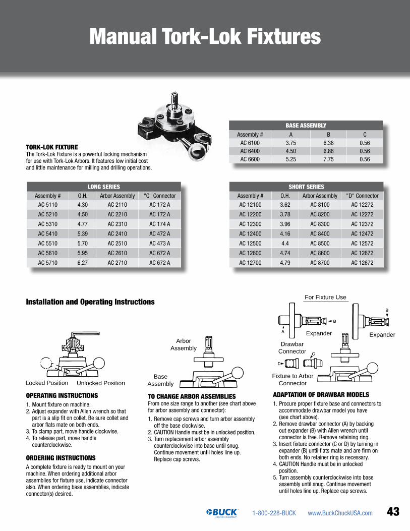
www.BuckChuckUSA.com1-800-228-BUCK 43
Manual Tork-Lok Fixtures
LONG SERIESAssembly # O.H. Arbor Assembly "C" Connector
AC 5110 4.30 AC 2110 AC 172 A
AC 5210 4.50 AC 2210 AC 172 A
AC 5310 4.77 AC 2310 AC 174 A
AC 5410 5.39 AC 2410 AC 472 A
AC 5510 5.70 AC 2510 AC 473 A
AC 5610 5.95 AC 2610 AC 672 A
AC 5710 6.27 AC 2710 AC 672 A
SHORT SERIESAssembly # O.H. Arbor Assembly "D" Connector
AC 12100 3.62 AC 8100 AC 12272
AC 12200 3.78 AC 8200 AC 12272
AC 12300 3.96 AC 8300 AC 12372
AC 12400 4.16 AC 8400 AC 12472
AC 12500 4.4 AC 8500 AC 12572
AC 12600 4.74 AC 8600 AC 12672
AC 12700 4.79 AC 8700 AC 12672
BASE ASSEMBLYAssembly # A B C
AC 6100 3.75 6.38 0.56AC 6400 4.50 6.88 0.56AC 6600 5.25 7.75 0.56
OPERATING INSTRUCTIONS1. Mount fixture on machine.2. Adjust expander with Allen wrench so that
part is a slip fit on collet. Be sure collet and arbor flats mate on both ends.
3. To clamp part, move handle clockwise.4. To release part, move handle
counterclockwise.
ORDERING INSTRUCTIONSA complete fixture is ready to mount on your machine. When ordering additional arbor assemblies for fixture use, indicate connector also. When ordering base assemblies, indicate connector(s) desired.
TO CHANGE ARBOR ASSEMBLIESFrom one size range to another (see chart above for arbor assembly and connector):
1. Remove cap screws and turn arbor assembly off the base clockwise.
2. CAUTION Handle must be in unlocked position.3. Turn replacement arbor assembly
counterclockwise into base until snug. Continue movement until holes line up. Replace cap screws.
ADAPTATION OF DRAWBAR MODELS1. Procure proper fixture base and connectors to
accommodate drawbar model you have (see chart above).
2. Remove drawbar connector (A) by backing out expander (B) with Allen wrench until connector is free. Remove retaining ring.
3. Insert fixture connector (C or D) by turning in expander (B) until flats mate and are firm on both ends. No retainer ring is necessary.
4. CAUTION Handle must be in unlocked position.
5. Turn assembly counterclockwise into base assembly until snug. Continue movement until holes line up. Replace cap screws.
Installation and Operating Instructions
TORK-LOK FIxTUREThe Tork-Lok Fixture is a powerful locking mechanism for use with Tork-Lok Arbors. It features low initial cost and little maintenance for milling and drilling operations.
Unlocked Position
ArborAssembly
BaseAssemblyLocked Position Unlocked Position
Expander Expander
For Fixture Use
DrawbarConnector
Fixture to ArborConnector

Logansport® 3-Jaw Compensating Power Chucks362, 364 & 370 Series
2155 Traversefield Dr. Traverse City, MI 49686Tel: 800-228-BUCKFax: 231-995-8362 [email protected]
Buck Chuck Company is your workholding solution.If there is something you need that is not featured here, please contact us. We may be able to help.
Logansport® Self Centering Power Chucks 352, 452, 430, 440, 330 and 340 series
BC 2012 V. 1
2-Jaw, 3-Jaw or 2/3-Jaw available – The Logansport® lever design offers a
high degree of mechanical advantage which, in turn, allows for the use of smaller
diameter rotating cylinders. Quality materials are used throughout and all center
parts are protected by pressure lubrication. Logansport® chucks have long enjoyed
a well-deserved reputation for durability and uninterrupted service. Available in 6” to
24” – other sizes upon request.
One Piece Body – The design simplicity of Logansport® chucks insures lasting
accuracy and efficiency. They are one-piece body, cored for lightweight and radially
reinforced for extra rigidity. Compensating power chucks are used for turning parts
between centers. Available in 6” to 24” – other sizes upon request.
ALSO AVAILABLE FROM BUCK
BUCK Extra Heavy Duty Oil Country Chucks
Scroll or Independent – Available in 25” to 80” sizes – solid or American standard
tongue & groove jaws. 3-Jaw scroll or 4-Jaw independent. Steel or cast iron bodies.
Master jaw and hardened reversible top jaw styling. Internal and external chucking
operations. Competitively priced. Direct mount conversion plates available. Adapters to
fit most common spindle types available – contact our sales office for more information.