build a safe bridge over worked coal mines -...
TRANSCRIPT

1
Build a Safe Bridge over Worked Coal Mines
Zichao Wu, Ph.D., P.Eng., PE, AECOM
Bo Hu, Ph.D., P.Eng., PE, AECOM
Sheldon Foley, P.Eng., Flatiron Construction
Rob Richardson, PE, Flatiron Construction
Paper prepared for presentation at Structures Session
of the 2015 Conference of the
Transportation Association of Canada Charlottetown, PEI
2
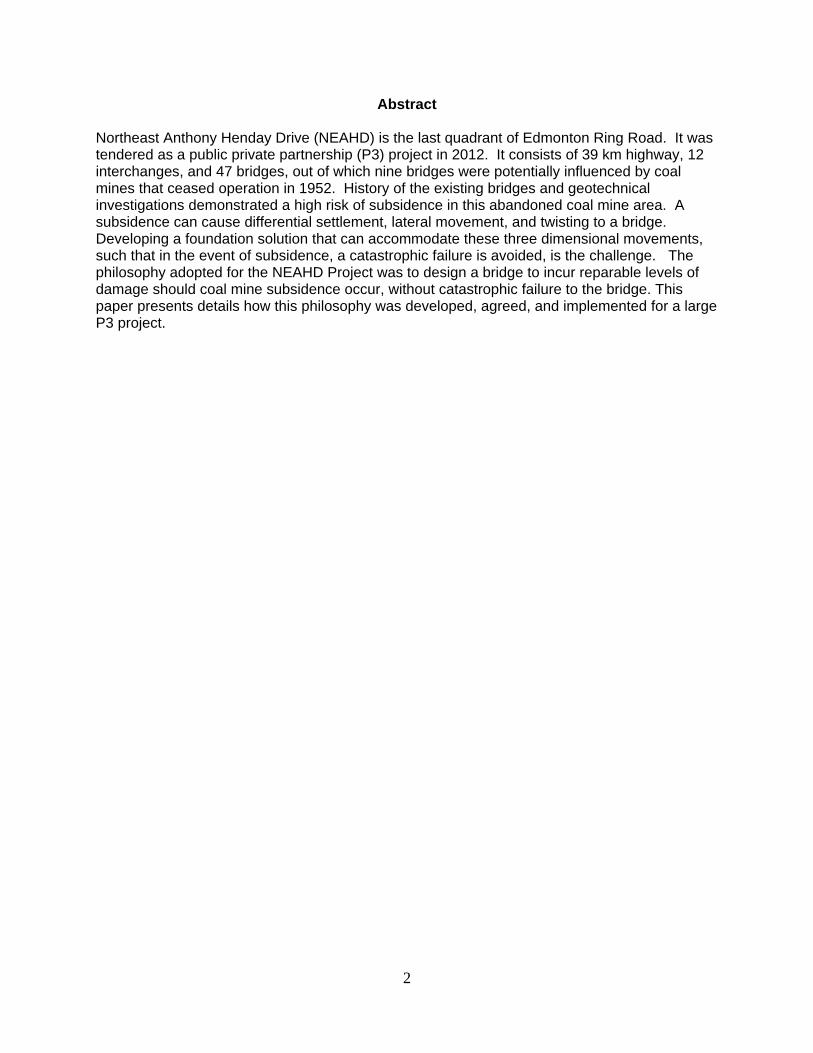
Abstract Northeast Anthony Henday Drive (NEAHD) is the last quadrant of Edmonton Ring Road. It was tendered as a public private partnership (P3) project in 2012. It consists of 39 km highway, 12 interchanges, and 47 bridges, out of which nine bridges were potentially influenced by coal mines that ceased operation in 1952. History of the existing bridges and geotechnical investigations demonstrated a high risk of subsidence in this abandoned coal mine area. A subsidence can cause differential settlement, lateral movement, and twisting to a bridge. Developing a foundation solution that can accommodate these three dimensional movements, such that in the event of subsidence, a catastrophic failure is avoided, is the challenge. The philosophy adopted for the NEAHD Project was to design a bridge to incur reparable levels of damage should coal mine subsidence occur, without catastrophic failure to the bridge. This paper presents details how this philosophy was developed, agreed, and implemented for a large P3 project.

3
Introduction Northeast Anthony Henday Drive (NEAHD) is the last quadrant of Edmonton Ring Road (Figure 1). It was put out for bidding as a public private partnership (P3) project in June 2011. It consists of 39 km highway, 12 interchanges, and 47 bridges. The Capital City Link Group (CCLG) consisting of Hochtief (project lead and financing), Flatiron (construction lead), AECOM (design lead), and Volker Stevin (operation and maintenance) was awarded the project in May 2012. Out of the 47 bridges nine bridges are potentially influenced by coal mines. Underground coal mines operated in NE area in Edmonton up to 1952, and used “room and pillar” mining system to extracted up to 2 m coal seams 25 to 43 m below the original ground surface. As shown in Figure 2 miners first cut a network of rooms into the coal seam, leaving a series of pillars of coal to support the roof of the mine. Then the pillars were mined, leaving the roof to collapse in a controlled way as miners retreated to the exit. The risk is in certain areas pillars might have been left in place after the mines ceased operation. The roof of any of the existing rooms might collapse at any time and cause ground subsidence. Mining subsidence, in most cases, causes differential displacement at ground surface in all directions and, when differential movement is substantial, could result in excessive displacement and overstress damages in various structural and non-structural components for bridges located within the affected zone. It has been a design challenge for engineers to provide technically feasible yet economically practical solutions to mitigate the potential damages. Engineering solutions for mining subsidence may be divided into two categories: subgrade improvement and structural accommodation of distortion or movement. Subgrade improvement is to minimize the risk of subsidence occurring and, if subsidence is unlikely to be prevented, to minimize the magnitude of surface movement. A typical measure in this category is grouting, filling mine voids with engineered grout. However, despite of its extremely high cost, grouting can only be successful when the site condition allows and a competent contractor executes a well-prepared plan. For some sites, certain additional load bearing capacity exists for the mine voids, reducing the stress surcharge through designing proper bridge foundations would be an effective solution to avoid subsidence. Structural accommodation of large ground movement should be ensured by both the foundation and the superstructure. Spread footings are the preferred foundation type, while one of the design challenges with pile foundations is the extremely high down drag forces when subsidence occurs. Double sleeved piles could be used to reduce down drag force. The preferred superstructure type is simply supported spans or well-articulated superstructures, such as cantilever and suspended spans. For design details, sufficient restraints should be provided to ensure no fall-off will happen for the superstructure. For certain projects, it may be economical to designate some structure components to exceed the elastic limits if subsidence occurs, but the designated structural elements needs to be inspectable and repairable. Despite of the design importance of mining subsidence, design guidelines for bridge structures have not been well developed yet. The Design Manual for Roads and Bridges in Britain contains a section on general rules for design of highway structures in areas of mining subsidence. Jones (1988), Gaffney et. al.(2002), Zhang and Choi(2013) have reported design case studies on bridge designs in mining subsidence areas.

4
This paper provides a case study on the bridge foundation design decision making procedure to accommodate potential coal mine subsidence in the NEAHD project in Edmonton, Alberta. As a public-private-partnership (P3) project, the liability that stakeholders carry is different from a traditional project, resulting in a different engineering decision making procedure and results.
Risk Management during Bidding Phase
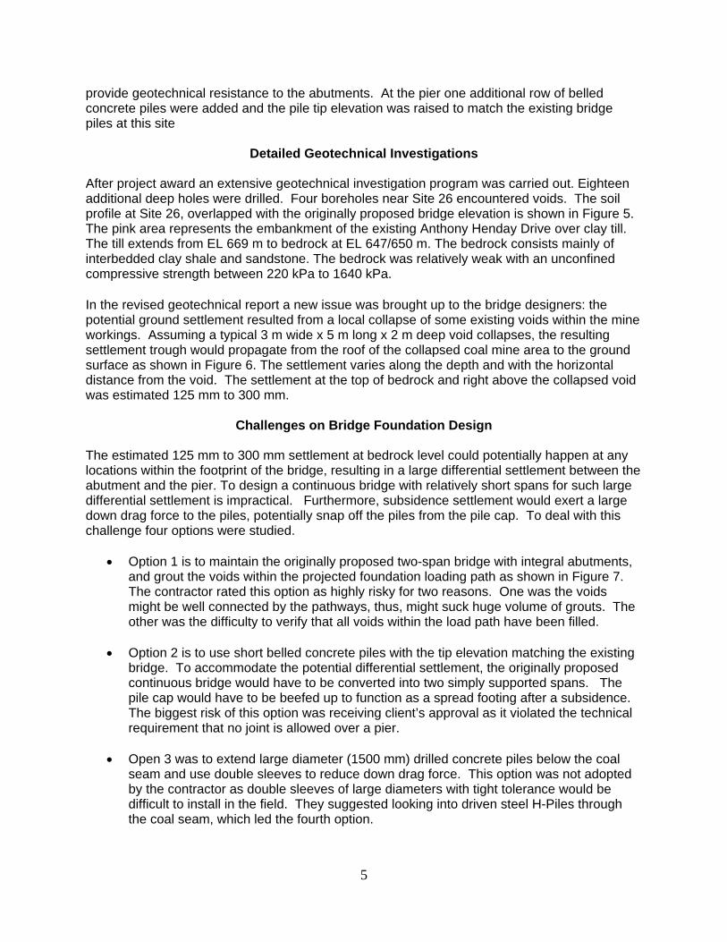
The coal mine issue was not specified in the RFP document. It was identified as a risk factor for design, construction, and thirty-year operation by the consortium. During the bidding phase the only available information was the Coal Mining Atlas of the Edmonton Region (R.S. Taylor, 1971) and Alberta Energy Resources Conservation Board (ERCB) archive maps. Overlapping the maps to the proposed NEAHD alignment revealed nine bridges at three sites (Site 23, 26, and 27) within the coal mine workings limit (Figure 3). Two deep boreholes, BH11-01CM at Bridge 26.1 and BH11-02CM at Bridge 23.7, were drilled with primary intent to identify depths to bedrock contact, depths to coal seam, and thicknesses of coal seam. Borehole BH11-01CM was advanced to a depth of 57.8 m and Borehole BH11-02CM to 32.8 m. In Borehole BH11-01CM coal seam was encountered at a depth of 46.9 m (Elevation 630.1 m) with a coal seam thickness of 1.9 m and 17 m overlain bedrock. The encountered coal seam confirmed the pillars in the abandoned coal mines. Mined rooms should be present around the pillar. In Borehole BH11-02CM a void was encountered at a depth of 25.3 m (Elevation 631.7 m). The void is overlain by 10 m thick bedrock. Assuming 6 m penetration of a driven pile into the bedrock, 4 m bedrock below the tip of the driven pile for sufficient support, and 2 m thick coal seam, the geotechnical engineer assessed that it would be necessary for the top of the coal seam to be located a minimum of 30 m (6 + 4 + 2 x 10 = 30 m) below the bedrock surface in order to significantly reduce the risk that void spaces or upward migration of rubble zones could result in loss of support for pile foundations. The reasoning behind the math is materials falling from the roof of collapsing coal workings will “choke off” within a vertical distance of ten times the coal seam thickness. Based on the drilling results a sinkhole type of failure at B27.1 is high and subsidence caused by mined room collapse at B26.1 is high. At this stage the project team had two options. One was to design the affected bridges as if there would be no voids in the entire area, but reserve contingencies to cover an extensive drilling program, at least one deep hole at each pier and abutment during detailed design phase. Should voids identified under the substructure, they should be infilled with grout. The second option would be to adopt a risk management approach whereby the bridges would be designed using conventional processes with no allowances made in the design for avoiding potential impacts to the structures due to future subsidence. This approach would require contingencies reserved for the maintenance contractor to address problems that might arise due to coal mine subsidence, with solutions being dependent on nature and severity of the problems. Bridge designers were requested to prepare the technical submissions by ignoring the potential coal mine subsidence, at the same time prepare a backup foundation design with pile tip elevation at or above the existing bridge piles. Figure 4 shows the two-span NU-girder bridge with integral abutments, which was accepted by the client (Alberta Transportation) as meeting the technical requirements. Driven steel H-piles were used to support the integral abutments while single row of belled concrete piles were adopted for pier foundation. The backup design with modifications to the pile foundation is shown at the bottom of Figure 4. The driven piles were replaced with steel H-piles cast in and projected from concrete piles. The projected H-piles provide flexibility for superstructure expansion and contraction while the concrete piles
5
provide geotechnical resistance to the abutments. At the pier one additional row of belled concrete piles were added and the pile tip elevation was raised to match the existing bridge piles at this site
Detailed Geotechnical Investigations
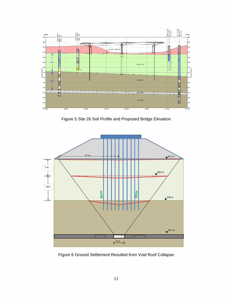
After project award an extensive geotechnical investigation program was carried out. Eighteen additional deep holes were drilled. Four boreholes near Site 26 encountered voids. The soil profile at Site 26, overlapped with the originally proposed bridge elevation is shown in Figure 5. The pink area represents the embankment of the existing Anthony Henday Drive over clay till. The till extends from EL 669 m to bedrock at EL 647/650 m. The bedrock consists mainly of interbedded clay shale and sandstone. The bedrock was relatively weak with an unconfined compressive strength between 220 kPa to 1640 kPa. In the revised geotechnical report a new issue was brought up to the bridge designers: the potential ground settlement resulted from a local collapse of some existing voids within the mine workings. Assuming a typical 3 m wide x 5 m long x 2 m deep void collapses, the resulting settlement trough would propagate from the roof of the collapsed coal mine area to the ground surface as shown in Figure 6. The settlement varies along the depth and with the horizontal distance from the void. The settlement at the top of bedrock and right above the collapsed void was estimated 125 mm to 300 mm.
Challenges on Bridge Foundation Design The estimated 125 mm to 300 mm settlement at bedrock level could potentially happen at any locations within the footprint of the bridge, resulting in a large differential settlement between the abutment and the pier. To design a continuous bridge with relatively short spans for such large differential settlement is impractical. Furthermore, subsidence settlement would exert a large down drag force to the piles, potentially snap off the piles from the pile cap. To deal with this challenge four options were studied.
Option 1 is to maintain the originally proposed two-span bridge with integral abutments, and grout the voids within the projected foundation loading path as shown in Figure 7. The contractor rated this option as highly risky for two reasons. One was the voids might be well connected by the pathways, thus, might suck huge volume of grouts. The other was the difficulty to verify that all voids within the load path have been filled.
Option 2 is to use short belled concrete piles with the tip elevation matching the existing
bridge. To accommodate the potential differential settlement, the originally proposed continuous bridge would have to be converted into two simply supported spans. The pile cap would have to be beefed up to function as a spread footing after a subsidence. The biggest risk of this option was receiving client’s approval as it violated the technical requirement that no joint is allowed over a pier.
Open 3 was to extend large diameter (1500 mm) drilled concrete piles below the coal
seam and use double sleeves to reduce down drag force. This option was not adopted by the contractor as double sleeves of large diameters with tight tolerance would be difficult to install in the field. They suggested looking into driven steel H-Piles through the coal seam, which led the fourth option.
6
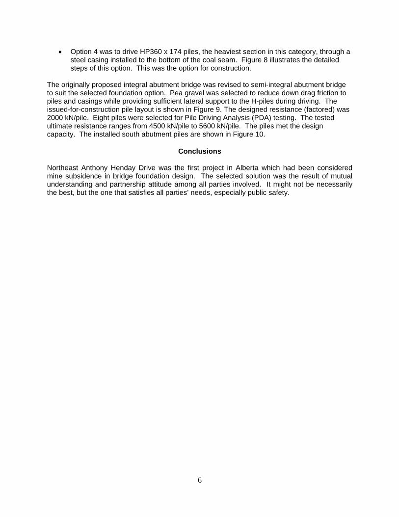
Option 4 was to drive HP360 x 174 piles, the heaviest section in this category, through a steel casing installed to the bottom of the coal seam. Figure 8 illustrates the detailed steps of this option. This was the option for construction.
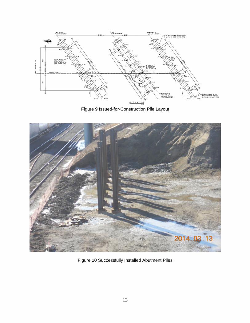
The originally proposed integral abutment bridge was revised to semi-integral abutment bridge to suit the selected foundation option. Pea gravel was selected to reduce down drag friction to piles and casings while providing sufficient lateral support to the H-piles during driving. The issued-for-construction pile layout is shown in Figure 9. The designed resistance (factored) was 2000 kN/pile. Eight piles were selected for Pile Driving Analysis (PDA) testing. The tested ultimate resistance ranges from 4500 kN/pile to 5600 kN/pile. The piles met the design capacity. The installed south abutment piles are shown in Figure 10.
Conclusions
Northeast Anthony Henday Drive was the first project in Alberta which had been considered mine subsidence in bridge foundation design. The selected solution was the result of mutual understanding and partnership attitude among all parties involved. It might not be necessarily the best, but the one that satisfies all parties’ needs, especially public safety.

7
References
Gaffney, D., Mayle, M., and Heirendt, K. 2002. “Underground Coal Mining along the Monday-Fayette Expressway: Issues, Assessment and Treatment”, Interstate Technical Group on Abandoned Underground Mine Workshop, May 1-3, 2002, Davenport, Iowa Jones, C.J.F.P. 1988. “The Effect of Mining Subsidence on a Motorway Bridge”, Proceedings of Second International Conference on Case Histories in Geotechnical Engineering, St. Louis, Missouri Taylor, R.S. 1971. Atlas: Coal Mine Workings of the Edmonton Area, Bulletin – Commercial Printers Limited, Edmonton. UK Department for Transport, Design of Highway Structures in Areas of Mining Subsidence, Design Manual for Roads and Bridges, BD 10/97, May 1997 Zhang, H.H. and Choi, B. 2013. “Foundation Design Challenges at Hunter Expressway Alliance Project in Australia”, New Frontiers in Engineering Geology and the Environment, Springer-Verlag, Nerlin Heidelberg

8
Figure 1 Edmonton Ring Road – Anthony Henday Drive
Figure 2 Room-and-Pillar Mining Diagram (https://wvcoalassociation.wordpress.com/news-comment/coal-mining-101/)

9
Figure 3 Coal Mine Limits and Affected Bridges

10
Figure 4 Bridge Elevation for Technical Submission (Top) and Backup Design (Bottom)
11
Figure 5 Site 26 Soil Profile and Proposed Bridge Elevation
Figure 6 Ground Settlement Resulted from Void Roof Collapse

12
Figure 7 Limits of Grouting at Abutment
Figure 8 HP360 x 174 Driven Pile Installation Procedures
13
Figure 9 Issued-for-Construction Pile Layout
Figure 10 Successfully Installed Abutment Piles