building energy analysis using cooling load …
TRANSCRIPT
BUILDING ENERGY ANALYSIS USING COOLING LOAD FACTOR/COOLING LOAD TEMPERATURE DIFFERENT (CLF/CLTD) METHOD
MOHD FIRDAUS BIN MUSA
Thesis submitted in fulfilment of the requirements for the award of the degree of
Bachelor of Mechanical Engineering with Automotive Engineering
Faculty of Mechanical EngineeringUNIVERSITI MALAYSIA PAHANG
DECEMBER 2010
i
UNIVERSITI MALAYSIA PAHANG
FACULTY OF MECHANICAL ENGINEERING
We certify that the project entitled “Building Energy Analysis Using Cooling Load
Factor/Cooling Load Temperature Different (Clf/Cltd) Method” is written by Mohd
Firdaus Bin Musa. We have examined the final copy of this project and in our opinion;
it is fully adequate in terms of scope and quality for the award of the degree of Bachelor
of Engineering. We herewith recommend that it be accepted in partial fulfillment of the
requirements for the degree of Bachelor of Mechanical Engineering.
MOHD RAZALI BIN HANIPAH
Examiner Signature
ii
SUPERVISOR’S DECLARATION
I hereby declare that I have checked this project and in my opinion, this project is
adequate in terms of scope and quality for the award of the degree of Bachelor of
Mechanical Engineering.
Signature:
Name of Supervisor: Mr. LUQMAN HAKIM BIN AHMAD SHAH
Position: LECTURER
Date: 6 DECEMBER 2010

iii
STUDENT’S DECLARATION
I hereby declare that the work in this project is my own except for quotations and
summaries which have been duly acknowledged. The project has not been accepted for
any degree and is not concurrently submitted for award of other degree.
Signature:
Name: MOHD FIRDAUS BIN MUSA
ID Number: MA07062
Date: 6 DECEMBER 2010
v
ACKNOWLEDGEMENTS
I am grateful and would like to express my sincere gratitude to my supervisor
Mr. Azizuddin Bin Abdul Aziz and my co-supervisor, Mr Luqman Hakim Bin Ahmad
Shah for their germinal ideas, invaluable guidance, continuous encouragement and
constant support in making this research possible. They’ve always impressed me with
their outstanding professional conduct, their strong conviction for science, and their
belief that a Degree program is only a start of a life-long learning experience. I am truly
grateful for their progressive vision about my training in science, their tolerance of my
naïve mistakes, and their commitment to my future career. I also would like to express
very special thanks for their suggestions and co-operation throughout the study. I also
sincerely thanks for the time spent proofreading and correcting my many mistakes.
My sincere thanks go to all the staff of the Mechanical Engineering Department,
UMP, who helped me in many ways and made my stay at UMP pleasant and
unforgettable.
I acknowledge my sincere indebtedness and gratitude to my parents for their
love, dream and sacrifice throughout my life. I cannot find the appropriate words that
could properly describe my appreciation for their devotion, support and faith in my
ability to attain my goals..

vi
ABSTRACT
This project is carried out to indentify whether the existing cooling capacity is suffice for an occupied building. The first objective of this project is to determine the heat gain of FKM Administration Building when it’s fully occupied. The second objective of this project is to compare the calculated heat gain against the existing cooling capacity. FKM Administration Building was chosen as the case study. The architectural drawingof FKM Administration Building is first studied to review the building specifications. The building specification is used in the calculation of heat gain in order to identify the cooling load required for FKM Administration Building. When FKM Administration Building is fully occupied, the number of occupant will be around 396 peoples. The type of air-conditioning system used in FKM Administration Building is central air conditioning system and the total existing cooling load is observed to be 381.8 kW. The peak heat gain is calculated as 492.7 kW using Cooling Load Factor/ Cooling LoadTemperature Difference (CLF/CLTD) method at 4 pm. Therefore, the existing coolingload is observed to be undersized in design. However, the peak heat gain will onlyhappen occasionally throughout the year. In order to overcome the undersized designcooling capacity problem, the cooling capacity should increase 29%.

vii
ABSTRAK
Projek ini dijalankan untuk menentukan kesesuaian kekuatan sistem penyejukan yang sedia ada dalam bangunan. Objektif pertama untuk projek ini adalah menentukan jumlah haba gandaan semasa bangunan dipenuhi oleh pengguna. Objektif kedua bagi projek ini adalah membanding antara jumlah haba gandaan dengan kekuatan system penyejukan yang sedia ada. Dalam projek ini, Bangunan Pentadbiran FKM dipilih sebagai kes pengajian. Pengajian atas pelan lantai Bangunan Pentadbiran FKM dibuat untuk mendapatkan butiran bangunan. Butiran bangunan akan diguna dalam pengiraan jumlah haba gandaan dan jumlah beban penyejukan yang diperlukan di Bangunan Pentadbiran FKM. Bangunan Pentadbiran FKM dapat menampung jumlah maksimun seramai 396 orang. Sistem penyaman udara yang dipakai di Blok W adalah sistem penyejukan udara berpusat dan jumlah kekuatan sistem penyejukan adalah 381.8 kW. Haba gandaan puncak berlaku pada jam pukul 4 petang dan nilainya ialah 492.7 kW dengan menggunakan kaedah Cooling Load Factor/ Cooling Load Temperature Difference (CLF/CLTD). Oleh demikian, kekuatan sistem penyejukan yang sedia ada adalah tidak mencukupi. Walaubagaimanapun, situasi sebegini cuma akan berlaku sekali sekala dalam setahun. Untuk mengatasi masalah tersebut, kekuatan sistem penyejukan perlu dinaikan sebanyak 29 %.
viii
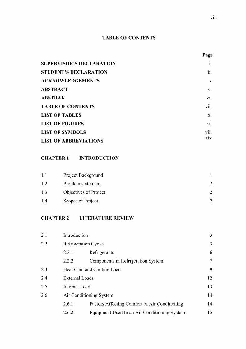
TABLE OF CONTENTS
Page
SUPERVISOR’S DECLARATION ii
STUDENT’S DECLARATION iii
ACKNOWLEDGEMENTS v
ABSTRACT vi
ABSTRAK vii
TABLE OF CONTENTS viii
LIST OF TABLES xi
LIST OF FIGURES xii
LIST OF SYMBOLS
LIST OF ABBREVIATIONS
viiixiv
CHAPTER 1 INTRODUCTION
1.1 Project Background 1
1.2 Problem statement 2
1.3 Objectives of Project 2
1.4 Scopes of Project 2
CHAPTER 2 LITERATURE REVIEW
2.1 Introduction 3
2.2 Refrigeration Cycles 3
2.2.1 Refrigerants 6
2.2.2 Components in Refrigeration System 7
2.3 Heat Gain and Cooling Load 9
2.4 External Loads 12
2.5 Internal Load 13
2.6 Air Conditioning System 14
2.6.1 Factors Affecting Comfort of Air Conditioning 14
2.6.2 Equipment Used In an Air Conditioning System 15

ix
2.6.3 Classification of Air Conditioning System 16
2.6.4 Chiller 16
2.6.5 Air Handling Unit 17
2.7 FKM Administration Building Specifications 19
CHAPTER 3 METHODOLOGY
3.1 Introduction 21
3.2 Literature Review 21
3.3 Review Building Specification 21
3.4 Heat Gains and Cooling Loads Calculations 22
3.4.1 The Cooling Loads Caused by Conduction of Heat
Gains through the Exterior Roof, Walls, and Glass. 22
3.4.2 Solar Radiation through Glass 22
3.4.3 Overall Heat Transfer Coefficient (U) 23
3.4.4 Corrected Load Temperature Different, CLTDc 23
3.4.5 Cooling Load Due To Heat Gain from Lighting. 22
3.4.6 Cooling Loads from Sensible and Latent Heat Gains
People 24
3.4.7 Cooling Load for Equipment 24
3.4.8 Cooling Load from Ventilation 25
3.5 Comparison between the Calculated Results against the Existing
Capacity of Air Conditioning Unit 25
3.6 Flowchart 26
CHAPTER 4 RESULT AND DISCUSSIONS
4.1 Introduction 27
4.2 Design Day 27
4.3 Heat Gain Calculation On The Design Day 29
4.3.1 Conduction through Exterior Structure 29
4.3.2 Solar Radiation Through Glass . 31
4.3.3 Peak Load Time 32
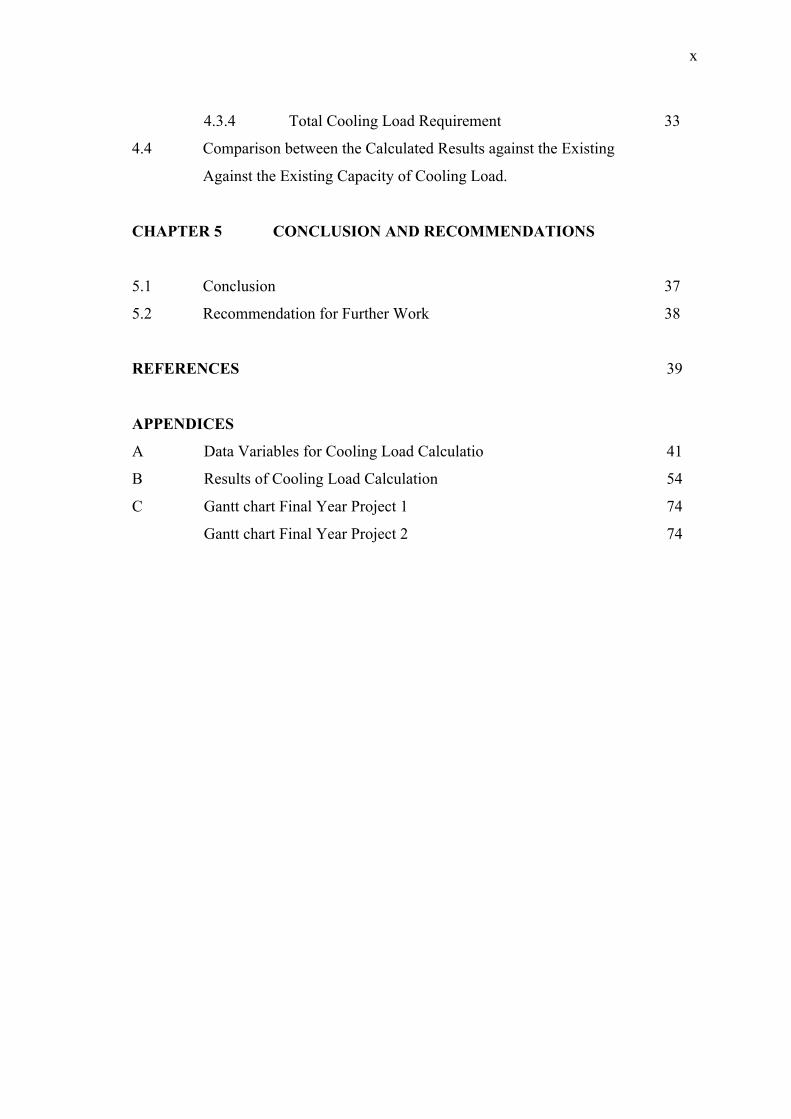
x
4.3.4 Total Cooling Load Requirement 33
4.4 Comparison between the Calculated Results against the Existing
Against the Existing Capacity of Cooling Load.
CHAPTER 5 CONCLUSION AND RECOMMENDATIONS
5.1 Conclusion 37
5.2 Recommendation for Further Work 38
REFERENCES 39
APPENDICES
A Data Variables for Cooling Load Calculatio 41
B Results of Cooling Load Calculation 54
C Gantt chart Final Year Project 1 74
Gantt chart Final Year Project 2 74

xi
LIST OF TABLES
Table No. Title Page
2.1 Air Handling Unit of FKM Administration Building’s specification
19
2.2 FKM Administration Building Specification 20

xii
LIST OF FIGURES
Figure No. Title Page
2.1 Refrigerator schematic diagram 4
2.2 Vapor-compression refrigeration cycle T-s diagram 5
2.3 Compressor 7
2.4 Condenser 7
2.5 Expansion valve 8
2.6 Evaporator 8
2.7 Heat flow diagram showing building heat gain, heat storage, and cooling load
11
2.8 Difference between instantaneous heat gain and cooling load as
a result of heat storage effect
12
2.9 Chiller's Room at UMP Campus Pekan 17
2.10 Maintenance accessories of large air handling unit 18
2.11 Air Handling Units (AHUs) in the FKM Administration Building
19
2.12 FKM Administration Building. 20
3.1 Flowchart of the project. 26
4.1 Maximum heat gain of FKM Administration Building from July to October 2010 28
4.2 Amount of heat gain for the conduction through exterior surface 30
4.3
4.4
4.5
4.6
Heat gain from the solar radiation through glass
Heat gain generated by the external heat gain in the FKM Administration Building
Maximum internal heat gain generated in the FKM Administration Building
Total amount of heat gain generated at the peak load time
32
33
34
35
xiii
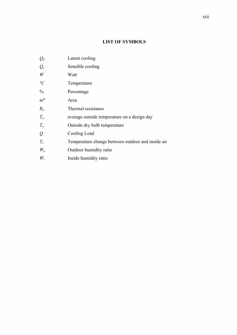
LIST OF SYMBOLS
QL Latent cooling
Qs Sensible cooling
W Watt
°C Temperature
% Percentage
m² Area
Ro Thermal resistance
Ta average outside temperature on a design day
To Outside dry bulb temperature
Q Cooling Load
Tc Temperature change between outdoor and inside air
Wo Outdoor humidity ratio
Wi Inside humidity ratio
xiv
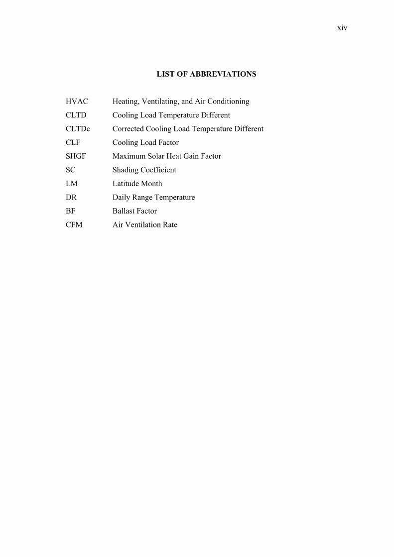
LIST OF ABBREVIATIONS
HVAC Heating, Ventilating, and Air Conditioning
CLTD Cooling Load Temperature Different
CLTDc Corrected Cooling Load Temperature Different
CLF Cooling Load Factor
SHGF Maximum Solar Heat Gain Factor
SC Shading Coefficient
LM Latitude Month
DR Daily Range Temperature
BF Ballast Factor
CFM Air Ventilation Rate
CHAPTER 1
INTRODUCTION
1.1 PROJECT BACKGROUND
Nowadays the environmental issues has become one of the most serious and
urgent problems in our era. Energy consumption by industries and buildings is
responsible for this problem. Thus, exact prediction of the heating and cooling load,
proper capacity of the Heating, Ventilating, and Air Conditioning (HVAC) systems are
essential and crucial to minimize energy consumption. A method for cooling load
calculations is essential in the design of air conditioning systems.
This project is carried out to analyze the most suitable capacity of air
conditioning unit that needs to be installed in the FKM Administration Building. In
order to analyze the most suitable capacity unit, an approach by using the Cooling Load
Factor/Cooling Load Temperature Difference (CLF/CLTD) Method has been used. The
architectural drawing of FKM Administration Building must be studied to identify the
type of materials used for the building construction and the exact dimension of the
building specification. To make sure this project is carried out smoothly, the
understanding of heat transfer knowledge is very crucial.
2
1.2 PROBLEM STATEMENT
The accurate calculation of heating and cooling loads is essential to provide a
sound bridge between fundamental building design decisions and an actual operating
building. If loads are substantially underestimated, occupants and users will likely be
hot. If loads are substantially overestimated, air conditioning equipment will be
oversized that usually resulted with wasting money, reducing efficiency and increasing
energy consumption. Nowadays most of the building used air conditioning units to give
comfortable situation to people especially in a closed space such as mosque, lecture
halls etc. Even so, most of the installing units are not suitable. Some of them are
undersize and some are oversized. Therefore a research is required to analyze the most
suitable capacity unit that needs to be installed.
1.3 OBJECTIVES OF PROJECT
The objectives of this project are:
(i) To determine the heat gain in the FKM Administration Building.
(ii) To compare the result obtained with the existing air conditioning units.
1.4 SCOPES OF PROJECT
The scopes of this project are:
(i) Literature study and understanding about air conditioning system of FKM
Administration Building.
(ii) Determination of the building material in order to determine the overall heat
transfer coefficient, U for FKM Administration Building.
(iii)Calculation of the heat gain in the FKM Administration Building according
to the Cooling Load Factor/Cooling Load Temperature Different Method
from July to October 2010.

CHAPTER 2
LITERATURE REVIEW
2.1 INTRODUCTION
This chapter discusses some literature reviews related to heat gain and cooling
load factor. It includes the process and components of refrigeration cycles and air
conditioning systems.
2.2 REFRIGERATION CYCLES
The term refrigeration as part of a building HVAC system generally refers to a
vapor-compression refrigeration cycle. The process wherein the heat is transferred from
a lower temperature region to a higher temperature region is called refrigeration. In the
vapor-compression refrigeration cycles, a chemical substance alternately changes from
liquid to gas (vaporized) and from gas to liquid (condensed). Refrigerators are cyclic
devices that perform the refrigeration process. The chemical substance (working fluid)
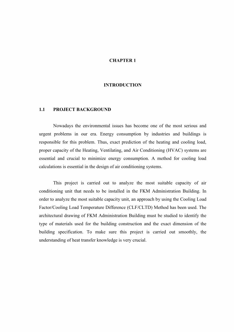
used in refrigerators are called refrigerants. The refrigerator schematic diagram is shown
in Figure 2.1. As shown schematically, is the magnitude of the heat which is
absorbed to the refrigerator from the cold refrigerated space at a low temperature, ,
is the magnitude of the heat rejected to the warm environment at a high temperature,
, and , is the net work input to the refrigerator that can be obtained from the
subtraction of and .
4
Figure 2.1: Refrigerator schematic diagram
Source: Cengel, Y.A. and Boles M.A. 2007
The vapor-compression refrigeration cycle has four components, namely
evaporator, compressor, condenser, and expansion valve. The vapor-compression
refrigeration cycle schematic diagram and T-s diagram is shown in Figure 2.2. The ideal
vapor-compression cycle consists of four processes:
(i) Isentropic compression in a compressor, 1-2.
(ii) Constant - pressure heat rejection in the condenser, 2-3.
(iii)Throttling in an expansion valve, 3-4.
(iv)Constant - pressure heat addition in the evaporator, 4-1.

5
Figure 2.2: Vapor-compression refrigeration cycle T-s diagram
Source: Cengel, Y.A. and Boles M.A. 2007
Based on the above diagram, the refrigerant enters the compressor at state 1 as
saturated vapor and is compressed isentropically to the condenser pressure. The
temperature of the refrigerant is increased during this isentropic compression process to
the temperature well above the surrounding medium temperature. The refrigerant then
enters the condenser as superheated vapor at state 2. In this compression process, state 1
to state 2, the low-pressure refrigerant vapor is compressed, thus raising the pressure
from to by expanding the mechanical energy done by the compressor ( , ).
From state 2, it then leaves as saturated liquid at state 3 resulted from the heat
rejection to the surrounding. The temperature at this state is still above the temperature
of the surroundings. In this process, state 2 to state 3, condensation process occur
wherein the high-temperature vapor is cooled by outdoor air or water that serves as a
‘heat sink’ and condenses it to liquid form at high pressure.

6
The saturated liquid refrigerant at state 3 is throttled to the evaporator pressure
by passing it through an expansion valve or capillary tube. The temperature of the
refrigerants drops below the temperature of the refrigerated space during this process.
From state 3 to state 4, expansion process takes place wherein the high-pressure liquid
that flows through an expansion valve is reduced. The phase is changed from the
saturated liquid refrigerant to the low-quality saturated mixture.
The refrigerant completely evaporates by absorbing heat from refrigerated space
after it enters the evaporator as a low-quality saturated mixture at state 4. The
refrigerant leaves the evaporator as saturated vapor and reenters the compressor,
completing the cycle. In this evaporation process, the low-pressure liquid absorbs heat
from indoor air or water and evaporates into vapor form. Then, the low pressure vapor
flows to the compressor and the process repeats itself (Cengel, Y.A. and Boles M.A.
2007).
2.2.1 Refrigerants
Any substance that termed as a refrigerant can absorb heat. Secondary
refrigerants, such as water or brine, absorb heat but they do not undergo a phase change
in the process. Primary refrigerants, then, are those substances that posses the chemical,
physical, and thermodynamic properties that permit their efficient use in the typical
vapor compression cycle. A refrigerant must satisfy several requirements before it can
operate in the vapor compression cycle as a working fluid (Stanford, H.W. 2003):
(i) The refrigerant must be chemically stable in both the liquid and vapor state.
(ii) Refrigerants for HVAC applications must be nonflammable and have low
toxicity.
(iii)Finally, the thermodynamic properties of the refrigerants must meet the
temperature and pressure ranges required for the application.
To be a good refrigerant, a compound has to live up to all these requirements.
Obviously, we want something that is nontoxic, chemically stable, and ozone-safe to
provide a better environment and secure from any harmful condition.

7
2.2.2 Components in Refrigeration System
The vapor compression refrigeration system consists of four components that
perform the four steps of the refrigeration cycle.
(i) Compressor: Compressor is the center of the refrigeration cycle. It works as a
pump to control the circulation of the refrigerant, and it adds pressure to the
refrigerant, heating it up. The compressor also draws vapor away from the
evaporator to maintain a lower pressure and lower temperature before sending it
to the condenser. Figure 2.3 shows an example of a compressor.
Figure 2.3: Compressor
Source: Whitman, W.C. Johnson, W.M. and Tomczyk, J. 2005
(ii) Condenser: It is the device that removes heat from the refrigerated space to the
surroundings. The heat absorbed from evaporator is drawn to the condenser
through the refrigerant to be removed to the surroundings. It is a heat exchanger
that cools the high-pressure gas so that it liquefies. Figure 2.4 shows an example
of a condenser.
Figure 2.4: Condenser
Source: Whitman, W.C. Johnson, W.M. and Tomczyk, J. 2005
8
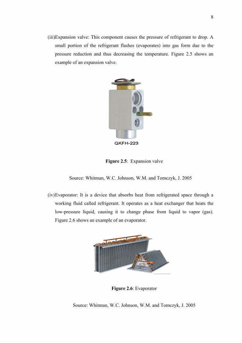
(iii)Expansion valve: This component causes the pressure of refrigerant to drop. A
small portion of the refrigerant flashes (evaporates) into gas form due to the
pressure reduction and thus decreasing the temperature. Figure 2.5 shows an
example of an expansion valve.
Figure 2.5: Expansion valve
Source: Whitman, W.C. Johnson, W.M. and Tomczyk, J. 2005
(iv)Evaporator: It is a device that absorbs heat from refrigerated space through a
working fluid called refrigerant. It operates as a heat exchanger that heats the
low-pressure liquid, causing it to change phase from liquid to vapor (gas).
Figure 2.6 shows an example of an evaporator.
Figure 2.6: Evaporator
Source: Whitman, W.C. Johnson, W.M. and Tomczyk, J. 2005

9
2.3 HEAT GAIN AND COOLING LOAD
The undifferentiated heat flow into a building or space are generally described as
‘heat gain’, which means that the amount of heat flowing into the building or space
resulting from any source that produces heat is considered as ‘heat gain’. The sources
could be building occupants, lights, appliances, and from the environment, mainly solar
energy. The portion of heat gain that would affect the air temperature (as opposed to
building material and content) at a given point in time is usually known as the cooling
load. This portion of heat gain will raise the temperature in the space or building, thus
resulting in an uncomfortable environment. In other words, cooling load is the amount
of heat that must be removed from a building to maintain a comfortable temperature for
its occupants. The cooling load is the basis for selection of the proper size of air
conditioning equipment and distribution system. It is also important in analyzing the
energy use and conservation. The following terms are commonly used to describe the
aspects of heating and cooling loads (Grondzik, W. 2007b):
(i) Block load: the diversified load that is used to size the Heating, Ventilating,
Air Conditioning, and Refrigerating (HVAC&R) systems. It is based upon
the consideration that not all perimeter zones in a building peak at the same
time. It is the maximum load that measuring equipment (air handler, chiller,
pump, and fan) actually detects. It is also called the refrigeration load and is
less than the sum of the peak loads.
(ii) Coincident load: a load that is occurs in coincidence (same time) with
another load such as a latent load that is coincident with a sensible load or a
solar load that occurs at the same time as occupancy load.
(iii)Design load: a load that represents the highest reasonable heating cooling
load likely to be experienced by a building based upon statistically
significant climatic data. Design load is not the highest load that may or can
occur, but, rather the highest reasonable load for design cost consideration of
equipment and energy-efficient operations.

10
(iv)Diversified load: the portion of the sum of the peak loads that is coincident.
Load diversity accounts for the fact that the peak loads in different building
zones often do not occur simultaneously. Therefore, the actual building peak
load is generally smaller than the undiversified sum of the zone peak load. In
a similar context, this term is also used to describe loads resulting from
equipment or appliances that do not operate at full load at all times. Accurate
cooling load estimates must reasonably account for such diversified
operation patterns, particularly in spaces such as labs where equipment loads
are an especially important concern.
(v) Dynamic load: a load that varies in intensity over time, it is usually increased
in small time steps, such as seconds or minutes.
(vi)Instantaneous load: a load that occurs during a defined time step or period,
usually one hour.
(vii) Peak load: the largest load occurring in a space, a zone, or an entire
building. In the building load context, it is the maximum simultaneously or
coincident load.
In the cooling process, the rate of heat received (heat gain) is not equal to the
heat removed (cooling load) from a space or building due to the heat storage and time
lag effects. Based on Figure 2.7, the amount of heat gain entering the building at any
time is divided into two parts. A portion of it heats the room air immediately through
convection and other part is drawn to the furnishings and building structure such as
roof, walls and floors through radiation process. This radiation process can be described
as heat storage effect. The heat stored in furnishings and structures then heats the room
air through convection after a delayed time. This is the time lag effect.