built-in gutter design and...
TRANSCRIPT

shy
Builtshyin Gutter Design and Detailing
Jeffrey S Levine Levine amp Company Inc Ardmore Pennsylvania
Proceedings of the RCI 23rd International Convention Levine 147
ABSTRACT Built-in gutters are a frequently mis-constructed roof component The basic princi-ples of thermal movement as well as their direct impact on material selection appear to be misunderstood by both design professionals and contractors Dubious details contained in some of the industrys standard reference manuals do not help the mat-ter Recommendations for proper built-in gutter design and detailing will be made including a discussion of the stresses imposed upon built-in gutter liners under ther-mal load seam selection rivet selection and spacing expansion joints and layout Common misconceptions concerning gutter design having to do with metal temper and gauge will also be examined
SPEAKER Jeffrey Levine is president of Levine amp Company Inc Roof Consulting and Architectural Conservation Mr Levines responsibilities include condition assess-ments leak investigations construction documentation and maintenance planning He has served as project manager for over 200 restoration and rehabilitation projects preservation plans and maintenance programs for a large variety of building types including academic commercial and ecclesiastical buildings Mr Levines expertise in the field of slate roofing is nationally recognized He has an MA in historic preser-vation planning from Cornell University has written numerous articles on slate roof-ing including Preservation Brief No 29 published by the National Park Service and is a founding director of the National Slate Association
Contact Information Phone ndash 610-642-4081 E-mail ndash jlevinelevineconet
Levine shy 148 Proceedings of the RCI 23rd International Convention
z
Builtshyin Gutter Design and Detailing
INTRODUCTION Built-in gutters are a fre-
quently mis-constructed roof component The basic principles of thermal movement as well as their direct impact on material selection appear to be poorly understood by both design profes-sionals and contractors Worse yet for years some of the indus-trys standard reference manuals on metal flashings and gutters have been offering questionable information to those charged with the design and construction of roof drainage systems As a result built-in gutters are often plagued by open seams fatigue cracks and loose-locked seams located within the one of ice damming
Incorrectly installed built-in gutters are not easily repaired Open seams cannot simply be re-soldered due to the presence of dirt and moisture within the failed seams Expansion joints cannot simply be installed after the fact if water flow to the outlets is to be maintained Gutter replacement is often the only long-term reme-dy but even this can be complex especially when tie-in with an existing standing seam or batten seam roof is required
After identifying common issues associated with the failure of built-in gutters thermal move-ment and the stresses imposed upon built-in gutter liners under thermal load will be discussed Basic principles associated with proper built-in gutter design and detailing will be outlined includ-ing expansion joint design seam selection rivet selection and spac-ing soldering pan orientation cleat type and outlet tube materi-als Common misconceptions
concerning gutter design having to do with metal temper and gauge will also be examined
Throughout the paper the issues discussed apply equally to pole gutters and box gutters as some of the illustrations will show Similarly although copper built-in gutters are most frequent-ly referenced in the paper the principles are also applicable to other metals commonly used in the fabrication of built-in gutter liners including lead-coated cop-per tinzinc alloy-coated copper stainless steel terne and TCS II (stainless steel sheet coated with a tinzinc alloy)
COMMON CAUSES OF PREshyMATURE BUILTshyIN GUTTER FAILURE
Reflecting back on a recent spate of projects and then even further to those completed over the past 20 years a common thread appeared problems with recently installed built-in gutters One might expect 50- to 60-year-old gutters to have problems Normal wear and abrasion at drip lines and outlet tubes will eventu-ally create holes and result in leaks It is when these ldquoold timersrdquo are replaced that the real prob-lems seem to arise More and more building owners and prop-erty managers are reporting prob-lems with built-in gutters installed within the past 10 years Observation usually reveals that even the 10-year-old gutters have been leaking for some time evi-denced by layers of past ineffec-tive repairs andor extensive dete-rioration of adjacent building sys-tems such as wood cornices roof framing and exterior masonry walls Further more often than not the roof systems above these
relatively new gutters ndash whether they be slate tile asphalt shin-gles standing seam or batten seam ndash are fine Analysis of the problems associated with recently installed built-in gutters suggests that their design and installation are not well understood by todays design professionals and contrac-tors The building owner frustrat-ed by the leaks just wants the problem to go away holding to the hope that inexpensive repairs will save the day and adverse to even the possibility of having to start and pay for a major construction project yet again Based upon over 20 years of observing what ldquoworksrdquo and what does not ldquoworkrdquo learning from past mis-takes and improving upon the designs of others it is hoped that this paper will assist those responsible for specifying detail-ing and constructing built-in gut-ters with creating gutters that have a good chance of actually reaching the end of their expected serviceable lives and becoming ldquoold timersrdquo
Open Seams and Fatigue Cracks
The most common problems associated with new built-in gut-ters are open seams and fatigue cracks (Figure 1) Unfortunately these problems are also the most difficult to repair and most likely to condemn the gutter installa-tion Open seams and fatigue cracks are typically caused by improper accommodation of ther-mal movement in the gutter liner Expansion joints are either not present or placed too far apart to be effective In addition the top edge of the gutter apron is quite often nailed to the roof deck rather than secured with cleats thereby restricting thermal move-
Proceedings of the RCI 23rd International Convention Levine shy 149
ment even if expansion joints are present These conditions are dif-ficult to repair for several reasons
1) Open seams cannot sim-ply be re-soldered to make them watertight Dirt and moisture within the cracked seam turns into a black goop when heated and prevents new solder from being sweated into the seam
2) Fatigue cracks can be patched with a copper ldquoplaterdquo riveted and sol-dered over the top of the affected area but such a repair should only be con-sidered temporary The underlying cause of the fatigue crack ndash stresses associated with expansion and contraction of the gut-ter liner ndash remain and will either cause the patch to fail or simply transfer the stress to another point resulting in another fatigue crack
3) Installation of expansion joints to better accommo-date thermal movement of the gutter liner is an obvi-ous solution but not read-ily achievable Traditional expansion joints are formed by placing end walls at the ends of two adjacent lengths of gutter and leaving a small space between them The end walls act as a dam and effectively prevent the flow of rainwater So adding expansion joints without re-sloping the gutters will prevent rainwater from reaching the downspouts Re-sloping of course re-quires removal and re-placement of the gutter liners
4) Replacement of the trou-blesome gutter liner is often the only effective option but again can be
Levine shy 150
Figure 1 ndash Open seam (left) and fatigue crack (right) in two difshyferent leadshycoated copper gutter liners Both are due to lack of expansion joints to accommodate thermal movement in the gutter liners
difficult to execute The gutter liner being at the roof eave is always in-stalled first extending up under the roof system When the roof system is comprised of slate shin-gles for example the bot-tom three or four courses of shingles can be re-moved salvaged and rein-stalled to allow gutter re-placement to occur When the roof system consists of standing seam or batten seam metal roofing the procedure becomes a bit trickier as the bottom sev-eral feet of roofing cannot easily be removed and re-installed As will be dis-cussed below the transi-tion between a new gutter liner and existing metal roofing is not widely cov-ered in standard industry publications and even if well executed it is rarely preferable to having the gutter liner installed first followed by the metal roof system
Open seams can also result from poorly soldered seams and seams that lack the proper strength to withstand the stresses imparted by thermal movement The fact is no matter how well designed a gutter might be a poorly soldered seam will eventu-ally fail In the end it all comes
down to good execution by the roofing mechanic Conversely a well-soldered seam will fail if the seams design does not properly consider the geometry of the gut-ter the gauge (thickness) of the gutter material and the anticipat-ed thermal loads
Other frequently encountered problems not directly related to thermal movement pertain to detailing at the outside edge of the gutter and at outlet tubes Where the built-in gutter sits behind a masonry parapet the outside edge of the gutter is often termi-nated or let into a reglet cut into the face of the parapets coping stone This is an aesthetically pleasing detail in that the observ-er at grade cannot see any hint of the rainwater conduction system (Figure 2) Unfortunately this detailing is prone to leakage as the reglet opens up The problem is exacerbated if the gutter liner is let directly into the reglet rather than being loose locked to a con-tinuous cleat or apron which in turn is let into the reglet The for-mer detail accelerates the rate of failure as it either 1) inhibits thermal movement resulting in open seams and fatigue cracks or more likely 2) causes prema-ture failure of the sealant or mor-tar filling the reglet as the diurnal juggernaut of thermal expansion and contraction continues unim-peded
Proceedings of the RCI 23rd International Convention
Figure 2 ndash The outside edge of this builtshyin gutter liner is let into a reglet in the limestone coping stone Compare this image to Reveres detail shown in Figure 7 Note too that the expansion joint is below the high water line of the gutter (comshypare to Figure 15)
Another problem with the out-side edge of built-in gutters occurs where the outside wall or leg is an integral part of the gutter framing or cornice and is set too low1 During heavy rainfall water rushing down the steep-slope roof above can simply ldquohop the curbrdquo and run down the exterior wall Both of the gutters shown in Figure 3 were originally designed by top-tier nineteenth-century architectural legends in the Philadelphia region The low out-side edge of the gutter on the left was found to be contributing to efflorescence and scaling of the interior brownstone walls of the church When informed of this the clients first question was
gutter
ldquoshouldnt we assume [the architect] knew how to design a gutterrdquo An intimidating question to say the least but the answer remains a resounding ldquonordquo
Premature failure often occurs at outlet tubes These areas are subject to the greatest wear as the greatest vol-ume of water passes through the outlet tubes The wear manifests itself as perforations or pin-holes in the copper The underlying problem is that the same weight cop-per was used to fabricate the outlet tube and the The goal should be to
anticipate the accelerated wear and use a heavier-weight copper for the outlet tube so that the outlet and the gutter can achieve similar service lives
Improper Repairs
Not only is built-in gutter design and construction plagued by problems the repairs imple-mented to address the faulty gut-ters are more often than not just as poorly conceived as the gutters themselves Examples abound but a few will suffice to make the point
Fabric tape and mastic (aka muck and fabric) is often placed atop open seams If the soldered
seam could not withstand the stresses of thermal movement why should fabric tape and mas-tic do any better Not only do they not hold up any better fabric tape and mastic also suffer from ultra-violet (UV) degradation and cause accelerated wear of the underlying copper by both corroding the cop-per and preventing the formation of a protective patina Fabric tape and mastic along with sealants and flashing tapes have their place They are well suited for short-term repairs Too often however they are relied upon as permanent fixes
Trough-level expansion joints although inferior to standard raised expansion joints are sometimes required and at least recognize that thermal movement of the gutter liner must be accom-modated With the installation of a trough-level expansion joint should come the recognition that it will have to be replaced periodi-cally at least several times over the life of the gutter itself The key word here is ldquoreplacedrdquo When repair consists of placing a second trough level expansion joint over an existing one a raised expan-sion joint is created due to the thickness of the materials in-volved This would be okay save for the fact that the gutter was designed to slope in one direction (with water passing over the expansion joint) not two The gut-ter shown in Figure 4 contains three trough-level expansion joints piled one atop the other All three leak and the puddle pic-tured slowly drains through the wood cornice below causing rot and deterioration along its way The destruction does not stop there however water exiting the wood cornice soaks into the soil at grade and has caused a rising damp problem in the brick masonry foundation
Figure 3 ndash The outside edge of these builtshyin gutters is set too Relining failed built-in gutters low In a heavy downpour rainwater can overshoot the gutshy with Ethylene Propylene Diene ters and run down the exterior masonry walls Monomer membrane (EPDM) is a
Proceedings of the RCI 23rd International Convention Levine shy 151
z
very popular solution in the Northeast Done right the EPDM can be expected to have service life of five to 10 years Done wrong as is typically the case and the leaks persist The leaks continue for several reasons 1) termination bars and fasteners are placed within the zone of ice damming 2) the membrane bucks water either at its interface with the roofing material (ie the membrane is not run up under-neath the roofing above) or by stopping mid-way up large gusset areas and valleys (Figure 5) 3) seams open up as the underlying metal liner moves under thermal load and 4) the EPDM mem-brane is simply not capable of conforming to multiple tightly spaced inside and outside cor-ners found in most built-in gut-ters (imagine a gutter-end wall expansion joint or outlet tube within a leader box)2
Figure 4 ndash Troughshylevel memshybrane expansion joint in a large builtshyin gutter Three expansion joints have been installed atop one another creating a dam The gutter outlet is located in the disshytance near the guttershyend wall
Repair of a faulty or worn out gutter liner is never as good or long-last-ing as a well de-tailed replacement On the rare occa-sion that replace-ment does occur however detailing at the interface of the gutter and the standing or batten-seam roofing above often leaves much to be desired Lapped and sealed seams are often employed as the gutter liner
Figure 5 ndash This leadshycoated copper builtshyin gutter has been reshylined with an EPDM membrane The exposed edge of the memshybrane bucks water at the valley Note too all of the tight inside and outside corners the membrane must accommodate
or an apron joined to the gutter liner is simply slid up below the roofing as far as possible and the seam covered with sealant Thermal movement quickly caus-es the sealant to fail subjecting the lap to leakage via capillary movement of water andor ice damming To hold the overlying roof down bolts are frequently set right down through the roofing and underlying gutter liner A neoprene washer is typically expected to do the trick and keep water out of the hole thus created The compression seal being relied upon quickly fails due to degrada-tion of the neoprene and backing out of the fastener under thermal loads In essence there is now a hole in the roofgutter liner every 12 to 24 inches on center
The Industry Does a Good Job but
The roofing industry ndash trade associations professional maga-ines manufacturers ndash does a
good job educating those in the field Built-in gutter details in sev-eral highly regarded and generally excellent publications are how-ever of dubious integrity Al-though it would be difficult for these publications to cover all conditions their general guidance would seem to be leading design-
ers and contractors in the wrong direction now and in the past
Even a cursory look at the fol-lowing five publications design manuals all reveals some signifi-cant problems
Copper And Common Sense Revere Copper Products Inc Rome NY 7th Edition (1982) and 8th Edition (2005) Referred to herein as ldquoRevererdquo
Architectural Sheet Metal Manual Sheet Metal and Air Conditioning Contrac-tors National Association (SMACNA) Chantilly VA 6th Edition (2003) Re-ferred to herein as ldquoSMAC-NArdquo
Designer Handbook Stanshydard Practices For Stainshyless Steel Roofing Flashshying Copings Specialty Steel Industry of North America Washington DC 1995 Referred to herein as ldquoSpecialty Steel Industryrdquo
Technical Manual for the Design and Construction of Roofs of Stainless Steel Sheet No 12 006 Nickel
Levine shy 152 Proceedings of the RCI 23rd International Convention
Development Institute and Japanese Stainless Steel Association Toronto On-tario Canada 1989 Re-ferred to herein as ldquoNiDIrdquo
Copper In Architecture Cop-per Development Associa-tion Inc New York NY 1992 Edition and 2007 online Edition Referred to herein as ldquoCDArdquo
LooseshyLocked Seams in the IceshyDamming Region
Placing a loose-locked seam at the top of the rear vertical leg of the gutter liner is shown in four of the five publications (Figure 6) This detail might be acceptable if the top of the rear leg is well above (say 12 or more inches depending on climate) the outside edge of the gutter or in regions of the country where ice damming is not likely to occur Otherwise the loose-lock seam will leak To be fair SMACshyNA states
ldquoThe metal roof system may need special features to lock to the gutter in a waterproof manner when ice dams are present with ponding beshyhind themhellip Use only oneshypiece combination guttershyflashing in areas of ice and heavy snowrdquo3
In its 1982 ed-ition Revere does show a gutter liner extending below a batten seam roof but only to illustrate the ldquoneedrdquo for a hold-down (Figure 7) In its 2005 edi-tion Revere offers that a second method is possi-ble whereby the gutter liner is formed to ldquoextend up on the roof deck to a point that will be at least six inches (6) under the roofingrdquo4 Al-though mention of this second method is helpful Revere does not indicate when it should be em-ployed In the end a picture is worth a thousand words and what is pictured ends up on architects detail sheets as shown in Figure 8
Figure 7 ndash Gutter holdshydown shown in Copper and Common Sense 7th ed p 64 and 8th ed p 4C6
Figure 8 ndash Detail for a residence in Maryland showing a loose lock seam between the leadshycoated copper roofing and stainlessshysteel gutshyter liner within the zone of potential ice damming Compare this Figure to the stanshydard details shown in Figure 6
Figure 6 ndash Four of the five design manuals consulted show looseshylock seams in the zone of possishyble ice damming From left Copper and Common Sense 7th ed p 63 and 8th ed p 4C5 Architectural Sheet Metal Manual 6th ed p 117 and Copper in Architecture 1992 ed p 445 and 2007 online edition In the latter detail the top inside leg of the gutter seems to be below the gutters outside edge
Proceedings of the RCI 23rd International Convention Levine shy 153
Figure 9 ndash Two gutter details showing the gutter liner nailed to the roof deck Left Designer Handbook Standard Practices For Stainless Steel Roofing Flashing Copings p 12 Right Gutter detail for a colshylege dining hall in Pennsylvania Note too how the roofing tile in the detail at right (labeled ldquoArchitectural shingle to match existingrdquo) minishymally laps the top edge of the gutter liner
Nailing the Top Edge of the Gutter Liner to the Roof Deck
While Revere and SMACNA do a very good job showing the use of cleats to accommodate thermal movement in gutter liners the Specialty Steel Industry incorrect-ly implies in its ldquoInterior Gutterrdquo detail that nailing the top edge of the gutter liner to the roof deck is acceptable (Figure 9) Again to be fair the note that accompanies the detail discusses the need to allow for expansion of the gutter liner but neither the note nor the detail recommend the use of cleats And again what is shown usually ends up on a design pro-fessionals detail drawing (Figure 9 right)
Insufficient Overlap of the Roofing Material
Detail C Built-in Gutter in the CDAs 1992 manual shows a 4-in-wide gutter apron loose locked directly to the bottom end of standing seam roof pans (Figure 10) Although the notes that accompany the detail recommend it for roofs with a slope of at least 6 in 12 it is poorly conceived and will be subject to leakage should ice damming occur The 2007 ver-sion of this detail is much im-proved showing the gutter apron
extending under the roof pans 4 in The notes that accompany the 2007 version once again state the detail is recommended for roof slopes of 6 in 12 or more Unfortunately the note goes on to state that ldquofor roofs with lower pitches see Detail Drdquo Detail D is shown herein in Figure 6 It is not the best of alternatives
Vertically Challenged Expansion Joints
Although Revere and SMACNA do an excellent job explaining the need to accommodate thermal movement in built-in gut-ters using expansion joints none of the publications offers design details that will remain leak free under snow and ice loads or in one instance should the gutter fill up with water due to a clogged outlet tube (Figure 11) In each of the details shown in Figure 11
side end of the expansion joint well below the out-side edge of the gutter itself Should the gutter fill up with water this expansion joint will most certainly leak Loose lock seams as between the expansion joint cap and end walls have no place within the trough of a built-in gutter
HoldshyDowns in the Gutter Trough
Revere recommends the use of hold-downs in built-in gutters to prevent lifting of the gutter liner The hold-down consists of brass screws set through
oversized holes in the gutter liner (to permit thermal movement to occur) at 48 in on center each with a washer and copper cap sol-dered over top In 1982 Revere stated that hold-downs are neces-sary where the ldquoback section [of the gutter] is merely an extension of the roof sloperdquo5 In 2005 Revere
the inside end of the expan- Figure 10 ndash Although recommended sion joints end walls and for roof slopes of 6 in 12 or more cap terminate at the loose insufficient overlap of the roofing lock located at the top of the and gutter apron could subject the rear vertical leg of the gut- loose lock seam to water penetration ter where it will be subject under ice damming conditions to water infiltration The Copper in Architecture 1992 ed p NiDIs detail depicts the out- 445
Levine shy 154 Proceedings of the RCI 23rd International Convention
Figure 11 ndash Vertically challenged expansion joints from left Copper amp Common Sense 7th ed p 61 and 8th ed p 4C4 Architectural Sheet Metal Manual 6th ed p 127 and Technical Manual for the Design and Construction of Roofs of Stainless Steel Sheet p 75 Compare these details to Figure 15
recommended hold-downs where the sloping portion of gutter liners or other large flat areas are wider than 18 in6 Experience has shown that not only are hold-downs rarely if ever installed (at least in the Northeastern region of the country) lack of hold-downs has not resulted in widespread failure due to lifting of gutter lin-ers While there may be instances where hold-downs are beneficial the temptation to penetrate the gutter trough with screws should be resisted in favor of an alternate design or the use of expansion cleats at transverse seams (Figure 12)
Repair Details
Repair details for built-in gut-ters are rarely found in design and installation manuals Revere included nine paragraphs of text and a detail drawing showing the ldquoMethod of replacing faulty gutter liningrdquo in its 1982 edition of Copper and Common Sense The entire subject seems to have been eliminated from the 2005 edition SMACNA dedicates seven para-graphs in an appendix to repair-ing and replacing metal roofs None however is directly related to built-in gutters None of the other publications provides infor-mation on gutter repair
Transverse Seam Design
Transverse seams occur in almost every built-in gutter Their design and detailing are critical to the watertightness of the gutter Of the five publications Revere dedicates the most space to seam design Revere recommends locked and soldered seams for gutter liners fabricated of 16- and 20-ounce copper sheet and lapped riveted and soldered seams for those fabricated of 24-and 32-ounce copper On the sub-ject of rivets Revere has become very precise but not very practi-cal In 1982 Revere recommend-ed the use of 316-in-diameter solid copper rivets with copper burrs or washers placed below the peened heads to prevent damage to the underlying copper It allowed however that ldquoseveral other types of rivets are satisfac-tory in making this type of seamrdquo7
In its 2005 edition Revere re-tracts the statement saying ldquoBe-cause of reduced joint strength Revere does not suggest the use of smaller diameter blind rivets [ie pop rivets] for structural joints in 24 ounce or heavier copperrdquo As if to apologize for precluding the use of pop rivets in 24- and 32-ounce gutter liners Revere states that it
helliprecognizes that peening solid rivets can be very diffishycult and laborshyintensive We also realized that it can be
exceedingly difficult to ldquobuckrdquo the concealed side end of rivets if a gutter lining is installed before the rivets are peened9
Revere goes on to suggest that to solve the problem gutter sections be joined in the shop or on the roof and then set in posi-tion in the gutter trough Can you imagine trying to set a 30- to 40-foot length of gutter in position without kinking it Solid copper rivets may provide the strength Revere is looking for to hold trans-verse seams together but there must be a better way In fact sev-
Figure 12 ndash Although this detail can not be found in any design manual such an expanshysion cleat may be a viable option for securing transverse seams in gutter liners where wind uplift is a concern
Proceedings of the RCI 23rd International Convention Levine shy 155
Figure 13 ndash Two poorly depicted seams in the CDAs Copper in Architecture 1992 ed p 445 top left By 2007 the detail had changed to that shown at the top right but the accompashynying note left the reader confused as to whether the seam should be locked and soldered or lapped riveted and soldered (Copper in Architecture 2007 online edition) One architects interpretation is shown at bottom a locked riveted and solshydered seam
eral practical options are given below in the Design Principles section of this paper
The other publications are not nearly as detailed as Revere in their recommendations for trans-verse seams SMACNA merely states that ldquoall joints must be lapped riveted and solderedrdquo10
The Specialty Steel Industry also recommends lapped riveted and soldered seams Neither associa-tion mentions rivet type The Specialty Steel Industry states that joint sealants may also be used That is unfortunate be-cause built-in gutter seams made watertight with sealant have no chance of remaining so Trans-verse seams in new gutters fabri-
Levine shy 156
cated of solderable metals such as copper and stainless steel should never be caulked or sealed
In its 1992 publication the CDA shows two variations for transverse seams a locked and soldered seam poorly represented by showing the solder just along the leading edge (ie not sweated all the way through the seam) and a soldered slip seam again with solder just on the leading edge (Figure 13) Neither of these seams possesses great strength and would surely crack after a few seasons of thermal movement in the gutter In the CDAs 2007 edi-tion the detail has appropriately changed to a lapped riveted and
soldered seam (see Figure 13) The note that accompanies the new detail is however confusing It reads
ldquoWhere seams occur in the copper gutter lining a locked and soldered seam is reshyquired to maintain a watershytight gutter condition The seam should be locked and soldered or riveted and solshydered so as to allow the water to flow away from the jointrdquo11
It is not entirely clear which seam is recommended An im-practical seam like the one shown in Figure 13 might result from such a note
Given all of the above it is not surprising that some questionable details are being put forth by design professionals In other cases the drawings simply side-step the details As one contractor recently stated ldquoWe dont usually get detail drawings for our [built-in gutter] work (except from you) as I think most architects shy away from that kind of stuffrdquo Anecdotal evidence as well as direct observation suggests that many contractors charged with the design of a built-in gutter are not aware of the laws of thermal expansion and contraction and simply use 16-ounce copper no matter the length or geometry of the gutter Sixteen-ounce copper will certainly be less expensive than heavier weights and easier to fabricate It also has a good chance of failing prematurely in long wide gutters due to the stresses associated with thermal movement
UNDERSTANDING THERMAL MOVEMENT
Built-in gutter problems are widespread due largely to ques-tionable workmanship and some questionable design standards The primary key to rectifying the situation is understanding the
Proceedings of the RCI 23rd International Convention
deg
Figure 14 ndash A portion of Reveres table for determining the spacing of expansion joints and weight of copper to be used in builtshyin gutters (Copper amp Common Sense 8th ed p 9B9)
dynamics of thermal expansion and contraction As Revere states ldquoWhen copper gutters are installed without proper consider-ation of the required columnar strength necessary to transfer movement failure in the copper sheet occursrdquo12
Revere has been a leader in the scientific study of thermal movement since the late 1930s when it was found that an increasing number of copper gut-ters were failing At the same time the design recommenda-tions of the copper and brass industry were called into ques-tion And rightly so as 16-ounce soft copper was recommended for virtually all copper flashings and gutters13 Reveres research led to a breakthrough in understanding the stresses imposed upon copper gutter liners undergoing changes in temperature
All metals expand and con-tract with changes in tempera-ture The degree to which they move varies and has been quanti-
Proceedings of the RCI 23rd International Convention
fied in a number called the Co-efficient of Thermal Expansion The Coefficient is expressed in inches per inch per degree Fahrenheit (inin F) Cold-rolled coppers Coefficient of Thermal Expansion is 00000098 while that of stainless steel (300 series) and aluminum (3003) are 00000096 and 00000129 re-spectively A 10-ft-long piece of copper sheet will thus increase in length approximately 02352 in over a 200-degree temperature change14 A 30-foot-long piece of copper will increase in length approximately 07056 in This movement cannot be stopped only accommodated If the move-ment is hindered as by nailing the top edge of the gutter liner to the roof deck or if too light a gauge is used given the length and shape of the gutter the cop-per will flex at some point along its length Repeated flexing will result in a fatigue or stress crack Imagine taking a wire hanger and bending it back and forth repeat-edly at its mid-point After a rela-
tively short while the hanger will snap in half due to metal fatigue
Since the thermal movement cannot be prevented it must be accommodated in the gutter design Three primary factors come into play in accommo-dating thermal expan-sion and contraction the weight or gauge of the copper the geome-try or shape of the gut-ter trough and the dis-tance between fixed points in the gutter (usually considered to be downspout locations and corners) or changes in direction The three factors are interrelated Change one and the others must change as well in order to effec-tively accommodate
thermal movement Stand a flat sheet of copper on end and it will crumple and fall over Bend that same piece of copper into a U shape and it will stand upright and might even take some addi-tional load pushing down on it Spread the sides of the U out too far (ie increase the angle between the sides and the bottom of the U) and it will topple Lengthen the U-shaped piece of copper several folds and it might crumple and fall over Increase the gauge of the copper sufficient-ly however and now it will stand upright These same concepts apply to a gutter liner laying hori-zontally in a gutter trough and are why the ability of a gutter liner to accommodate thermal movement is sometimes referred to as its ldquocolumnar strengthrdquo
One of the results of Reveres pioneering research is a concise table that quantifies the above concepts allowing one to deter-mine the appropriate copper gauge for a gutter liner given its
Levine shy 157
Figure 15 ndash Builtshyin gutter expansion joint with its outside edge raised 1 inch above the gutters high water line Detail by the author
shape and the distance between fixed points A portion of Reveres table is reproduced in Figure 14 Using the built-in gutter shown in Figure 8 as an example if the dis-tance between two downspouts is 60 ft an expansion joint is to be placed at the mid-point between the two downspouts the maxi-mum angle is 90deg the minimum angle is 70deg (not 110deg) and the trough width is 5-12 in then 24-ounce copper is required for the gutter liner Note that the gutter width was rounded up to the nearest width given in the table (6 in) and that the minimum angle was rounded down to the nearest angle given (60deg) These roundings are conservative in nature in both cases essentially supposing the gutter geometry to be ldquoweakerrdquo or less able to transfer thermal movement in the gutter liner to the expansion joint That is the actual gutter liner with a trough width of 5-12 in and minimum angle of 70deg will possess greater columnar strength than calculat-ed and should be able to transfer movement over even a greater dis-tance than the 33 ft derived from
Levine shy 158
the table Usually the longest dis-tance between an expansion joint and fixed point in a gutter system is selected as the ldquoworst-caserdquo scenario and the copper gauge thus calculated is used for all of a buildings gutters If one gutter section especially long however it is perfectly acceptable to calculate one copper gauge for it and anoth-er for the shorter gutters In the example above if the distance between the expansion joint and downspout in all of the buildings other gutters is only 20 ft 16-ounce copper could be employed in these gutters thereby reducing the cost of material significantly
Problems frequently arise right off the bat in gutter replace-ment projects when the calcula-tions for determining the copper weight required reveal that the thermal loads will not be carried to the expansion joints That is the gutter geometry and distance between expansion joints and fixed points is such that even 32-ounce copper will not possess the columnar strength required to ldquomake itrdquo to the expansion joints
In these situations it is often nec-essary to alter the gutter layout adding downspouts (fixed points) and expansion joints15 Some resloping of the gutter trough will also be required in order for rain-water to slope to the new down-spout locations When determin-ing the new gutter layout care must be taken to avoid placing new downspouts in line with existing window and door open-ings The moral is do not assume that the designer or contractor before you got it right It is impor-tant to run through the steps nec-essary to determine gutter gauge and maximum safe distance between expansion joint and fixed point for each building and some-times for each gutter in a given building
Two common misconceptions related to thermal movement in gutters prevail among design pro-fessionals and contractors The first surely dates back to the early 20th century It posits that soft copper is best for use in built-in gutters because it can better flex to accommodate the inevitable
Proceedings of the RCI 23rd International Convention
expansion and contraction of the copper that occurs with changes in temperature While this is true as explained earlier all that flex-ing will eventually lead to metal fatigue and a gutter leak16 The second posits that the thicker the copper sheet used to fabricate a gutter liner the more the gutter will expand and contract along its length This is incorrect as the coefficient of thermal expansion is a constant It does not vary with a materials thickness17
BASIC PRINCIPLES OF BUILTshyIN GUTTER DESIGN
Now that the weight of the copper sheet required has been determined based on the geome-try of the gutter and distance between expansion joints and fixed points the real detailing can begin Guidelines are given below for the detailing of expansion joints transverse seams and a host of other important features critical to the long-term function-ing of built-in gutters Soldering is perhaps the most critical workmanship issue in the instal-lation of built-in gutters And while one cannot design good workmanship several specifica-tion requirements can help to ensure high-quality soldering in the field
Expansion Joint Design
Expansion joints should be of raised design formed by riveting and soldering end walls to the adjacent ends of gutter length and then loose-locking a copper cap over the space left between the two end walls This is all fairly straightforward and as shown in most of the design manuals previ-ously surveyed The real key to a leak-free expansion joint is three-fold 1) raise the outside end of the expansion joint above the out-side edge of the gutter (ie get it above the gutters high-water line) 2) run the expansion joint up under the roofing material as far as the gutter apron again tak-
ing the top inside edge of the expansion joint well above the gutters high-water line and 3) solder a small diverter on the expansion joints cap to direct rainwater into the gutter trough rather than over the edge of the gutter (Figure 15)
Seam Selection and Detailing
Locked and soldered trans-verse seams or lapped riveted and soldered transverse seams That is the question Lapped riv-eted and soldered seams are pre-ferred They are strong water-tight and easier to install than locked and soldered seams Rivets provide the strength Solder pro-vides the waterproofing Forming is as easy as lapping one pan atop the other in the direction of water flow Locked and soldered seams fall short in terms of ease of installation which can result in a weaker and sometimes leaky seam The problem arises at the inside corners formed by the intersection of the gutter trough and inside and outside legs of the gutter In order to get two adja-cent gutter pans to lock some mechanics will snip a small ldquoVrdquo out of the under-folds and over-folds This creates small points of weakness in the finished seam that can crack under thermal loads snow loads and the stress-es associated with foot traffic
When designing a lapped riv-eted and soldered seam the fol-lowing details should be consid-ered 1) Adjacent lengths of gutter should be lapped 1-12 inches 2) Rivet pattern and spacing is criti-cal Generally rivets are placed 12 inch in from each edge of the seam and laid out in two rows in a staggered pattern The spacing between rivets within each row and the type of rivet employed depend largely on the weight of the copper being joined and the anticipated stress on the seams So for instance copper pop rivets spaced at 2-12 inches to 3 inch-es on center are usually adequate
for 16- and 20-ounce copper gut-ter liners Stainless steel pop riv-ets spaced closer together will provide added strength and should be considered for 24-ounce copper Stainless steel pop rivets spaced closely together may also be adequate for small gutters constructed of 32-ounce copper Solid copper rivets should be con-sidered for large 32-ounce copper gutter liners 3) Stainless steel riv-ets tend to be a little more difficult to solder than copper rivets Thorough fluxing of the rivet heads is critical 4) The mandrel portion of pop rivets should be constructed of the same material as the rivet head or one that is galvanically compatible with the head Avoid the use of steel and copper-plated steel mandrels when using copper rivets as these will leave unsightly rust stains at the seams A magnet is a handy way to tell a copper-plated mandrel apart from a solid copper or brass mandrel
Soldering
No procedure in the fabrica-tion and installation of built-in gutters is more critical to the gut-ters watertightness than solder-ing The topic of soldering de-mands an entire article in itself In addition to selecting the correct flux and solder removing any residues left over from the manu-facturing process cleaning the edges to be joined to bright metal pre-tinning copper and cleaning residual flux after soldering is complete there are at least three additional critical steps that should be specified and followed
First the seam should be sol-dered the same day it is formed on the roof This will help keep dust dirt rainwater dew and conden-sation out of the joint and make the task of soldering easier and more effective If the seams can-not be soldered the same day they should be protected until sol-dering can be take place Sim-ilarly if there are other construc-
Proceedings of the RCI 23rd International Convention Levine shy 159
tion activities generating a lot of dust in the vicinity of where seams are being formed such as raking out of mortar joints or reglets installation of the seams should be postponed until the other activity has ceased
Second the correct iron must be used Gone are the days when the sheet metal mechanic used a fire pot and a pair of coppers (sol-dering irons) weighing 6 to 10 pounds per pair Continuously heated irons are very common today on account of the increased productivity they offer That is okay but the soldering tip on the continuously heated iron must still be in the 1- to 2-pound range in order to sufficiently heat all lay-ers of metal within the seam and get the solder to flow or sweat through the entire seam Smaller irons cannot do this even if they are held in one place for a longer period of time Seams soldered with irons that are too small have solder primarily along their lead-ing edge and tend to crack and fail prematurely
Third mechanics should be tested and pre-qualified to per-form soldering prior to the start of construction on site Once in place in a gutter it can be difficult to verify whether a seam is sol-dered well without destructive testing Full-time field observation of soldering operations would be ideal but too expensive for most projects to bear The next best thing is to require each roofing mechanic anticipated to be involved in soldering to submit 12-in long samples of locked and soldered and lapped riveted and soldered seams for approval The back side of the sample seams can be easily observed and the samples can be cut in half across the seam to further verify that the solder has been sweated through all layers of metal the full width of the seam Mechanics whose seams are rejected should not be permitted to undertake soldering
Levine shy 160
work on the project Periodic unannounced testing of pre-qual-ified mechanics throughout the course of the project may also be appropriate in some situations
Gutter Pan Orientation and Cleat Location
In most built-in gutters gutter pans should be formed in 8- to 10-ft lengths and laid longitudi-nally This will eliminate from 55 to 63 of the seams the weakest points in the gutter If the total girth of a gutter is much larger than 3 ft (the width of a typ-ical copper sheet) then it may be necessary to consider other options These include laying the pans transversely using flat-seam copper pans (18 in x 24 in maximum size) and switching to another material such as a fluid-applied membrane waterproofing system (which has no seams)
Regardless of whether the gut-ter pans are laid longitudinally or transversely standard-type cleats should not be installed at the transverse seams as they would inhibit thermal movement of the gutter liner If wind uplift is a con-cern or if cleats are necessary to help the new gutter liner to lay flat expansion cleats may be used (Figure 12)
Cleats should be installed along the top (inside) and bottom (outside) edges of the gutter liner to allow the gutter to expand and contract longitudinally The cleats should be spaced at about 12 inches on center and secured with two nails each to prevent the cleats from rotating and pinching the gutter liner Laid out in this way the cleats not only help to hold the gutter liner in place but also act as guides as the copper liner moves under thermal load
In most US climates (except perhaps the desert southwest) the temptation to loose-lock a separate gutter apron to the gut-ter trough (at the top of the gutter
liners inside vertical leg) should be avoided To take it a step fur-ther not only should the gutter apron be continuous with the gut-ter trough it should also extend up the roof slope to a point at least 1 to 3 inches above the out-side edge of the gutter Where the build-up of snow and ice in the gutter can be expected and where ice damming might be anticipat-ed it is sometimes prudent to construct a continuous watertight system between the gutter apron and roof system above One way to achieve this is to strip-in the top edge of the gutter apron with a self-adhering ice dam protection membrane In order to be effec-tive the top edge of the stripping must be adhered directly to the roof deck with the roofing mater-ials underlayment lapped atop it
Tight tolerances can be tough to achieve in building construc-tion One that should be observed pertains to the gutter trough The bottom of the gutter trough must be kept in direct contact with the substrate material (usually wood sheathing felt and rosin paper) If the substrate is not a perfect plane the gutter liner will span between the high and low points in the substrate and be subject to kinking under load whether that load stems from foot traffic water-soaked leaves and debris ponded water or snow and ice Minor unevenness in the sub-strate usually can be leveled by installing additional layers of roof-ing felt andor resin paper in the low areas of the substrate If major troughs and crests are pre-sent in the substrate strong con-sideration should be given to repairing or replacing the trough to achieve a planar surface
Outlet Tubes and Overflow Scuppers
Outlet tubes suffer from more wear than any other portion of the gutter liner due to the greater quantity of water flowing through
Proceedings of the RCI 23rd International Convention
the outlet Knowing this it is pru-dent to use a heavier gauge metal for the outlet tube than the gutter liner itself For example if the gutter liner is fabricated of 20-ounce copper 24-ounce copper might be used for the outlet tube In all cases the longitudinal seam in the outlet tube must be well soldered along its entire length Alternatively outlet tubes can be fabricated of Drain Waste and Vent (DWV) solid copper drainage tube for even greater wear resis-tance Four-inch-diameter DWV tubing has a wall thickness of approximately 0058 inches nearly 80 thicker than 24-ounce copper sheet Another advantage of DWV copper tubing is that it has no longitudinal seams to leak or burst apart Joints between adjacent lengths of DWV copper tubing should be sweated with solder like copper plumbing Use emery cloth to clean the joint area flux-core solder and a torch to sufficiently heat the copper19
Whether sheet copper or DWV copper tubing is used the 12-in flange at the top end of the outlet tube must be continuous and free of splits and snips which create points of weakness in the riveted and soldered seam between the outlet tube and gutter liner20
Lastly the outlet tube and down-spout should have approximately the same cross-sectional area
If the gutter trough is very deep allowing large pools of rain-water to collect should the outlet tube(s) become clogged overflow scuppers should be installed Overflow scuppers should be placed several inches above the outlet tube (in a parapet wall for example) be the same size as the outlet tube and sloped at a down-ward angle to the outside Since they hopefully will be put to use with much less frequency than the outlet tube itself overflow scupper tubes can be fabricated of the same weight metal as the gutter liner
Gutter Replacement
When a relatively new gutter is in such poor condition that it must be replaced the design prin-ciples outlined above all apply The tricky part however can be in integrating the new built-in gutter with the existing roof sys-tem If the existing roof system consists of individual units such as slate or tile it is relatively easy to remove salvage and reinstall the shingles to permit gutter re-placement Similarly asphalt shingles can be removed and sim-ply replaced to allow the new gut-ter to be set in place first followed by the overlying roofing If the existing roof system consists of standing or batten-seam copper roofing the task becomes more difficult The question becomes how does one get the new gutter up underneath the existing roof-ing without having to remove the entire roof
With a batten seam roof it is often possible to cut the nails securing the wood batten to the roof deck using a reciprocating saw or slate ripper and then slide the new gutter apron up below the batten seam roof pans Since the upper portion of the trans-verse seams in the gutter apron cannot be soldered once installed (they are now below the roof pans) they must be soldered beforehand This in turn re-quires that the apron be slid into place in long lengths equal to the distance between expansion joints Once in place the apron can be locked and soldered or lapped riveted and soldered to the gutter liner and the battens re-secured to the roof deck using screws set through the top of the battens (ie out of the major flow areas) an inch or two above the top edge of the gutter apron The screws must be covered with cop-per caps soldered to the battens to make them watertight
With a standing seam copper roof there is no good place to
locate screws for re-securing the pans to the roof deck And since the top edge of the new gutter apron cannot be cleated to the deck (it is below the roof pans) securing the bottom edge of the roof pans with clips soldered to the gutter apron will not work -one unsecured element is being fastened to another One solution is to cut the existing gutter liner removing that portion which is in the trough and leaving the gutter apron in place The new gutter liner can then be locked and sol-dered or lapped riveted and sol-dered to the gutter apron Of course this solution will not work in all circumstances For exam-ple the existing gutter apron may not extend far enough up below the standing seam pans may be nailed rather than cleated to the roof deck or be in poor condition itself In such cases the unique aspects of the particular project such as the overall condition of the roof gutter configuration budget climate etc will play a large part in determining an appropriate course of action
Other Design Considerations
Other important considera-tions in the design and installa-tion of built-in gutters include their size in relation to the roof area they will serve and rainfall intensity for the region their depth-to-width ratio sacrificial flashings redundant waterproof-ing systems heat-trace systems and the number location and capacity of the downspouts serv-ing the gutters Some of these top-ics are well covered in other pub-lications21
When detailing a gutter it is best to think about it under the worst of conditions - not under the sporadic gentle rain but rather in the middle of a drench-ing downpour with the outlet tubes completely clogged or in the days after a major blizzard with the trough packed full of snow and ice Try to imagine how
Proceedings of the RCI 23rd International Convention Levine shy 161
z
the gutter will drain where the water will travel to and if there is ice damming where might that alternating layer of water and ice penetrate If the gutter liner is designed and installed with the worst of possible conditions in mind it should be able to handle these situations and anything else Mother Nature throws at it
FOOTNOTES
1 Although it is possible to set the outside edge of the gutter too high resulting in an inefficient depth-to-width ratio or inadequate strength to resist snow and ice loads the condi-tion does not appear to be a common one
2 Fluid-applied membrane waterproofing systems with conformable reinforc-ing mats might be a more lasting re-lining option but seem to be infrequent-ly employed perhaps due to cost or unfamiliarity with the systems available
3 Architectural Sheet Metal Manual 6th ed (Chan-tilly VA Sheet Metal and Air Conditioning Contrac-tors National Association 2003) p 116 The text goes on to reference Figure 6-16 but the figure is of little help
4 Copper and Common Sense 8th ed (Rome NY Revere Copper Products Inc 2005) p 4C6
5 Copper and Common Sense 7th ed (Rome NY Revere Copper Products Inc 1982) p 62
6 Copper and Common Sense 8th ed p 4C3
7 Copper and Common Sense 7th ed p 14
8 Copper and Common Sense 8th ed p 27
9 Ibid p 5B7
10 Architectural Sheet Metal Manual p 116
11 ldquoCopper In Architecturerdquo online ed (New York NY Copper Development Asso-ciation Inc 2007)
12 Copper and Common Sense 7th ed p 62
13 Dave Hunt ldquoUsing Com-mon Senserdquo Metalmag Vol 8 No 3 (MarchApril 2007) p 96 As late as 1942 one popular publica-tion stated ldquoIt is the con-sensus opinion that the best material for gutter lin-ing is in the order named soft copper lead tin and galvani ed ironrdquo (Ander-son Edwin P Sheet Metal Pattern Layouts (New York NY Theo Audel amp Co Publishers 1942) p 620)
14 ∆L = Lo x C x ∆T where ∆L is the change in length Lo is the initial length of the gutter C is the coefficient of thermal expansion (a constant) and ∆T is the change in temperature Thus 120 in x 00000098 x 200 degrees = 02352 in or approximately 1564 in It should be noted that many design manuals assume a 100-degree change in temperature In the northeastern United States a 200-degree sea-sonal temperature change is a more prudent assump-tion given nighttime win-ter lows at or below zero and summertime highs at around 100 degrees F It is important to keep in mind that the temperature of copper in direct sunlight in the summertime will be much greater than the ambient air temperature Note as well that expan-
sion across a gutters width is usually ignored except for very wide gut-ters A 16-in-wide gutter trough for example will increase in width approxi-mately 132 inch over a 200-degree temperature change well below the tol-erance possible in the fab-rication of a built-in gutter liner
15 Changing the gutter geom-etry is another option but either not possible or not alterable enough to make much of a difference For example changing the minimum angle of the gut-ter in Figure 8 from 70deg to 90deg by adding blocking will result in an increase of just 3 ft in the maximum safe distance between expansion joint and fixed point (see Figure 14)
16 It is important to recognize that built-in gutter liners do not behave like flat-seam copper roofing pans The latter are essentially flat sheets able to billow or ldquooil-canrdquo as they heat up and expand Built-in gut-ter liners for all practical purposes cannot oil can longitudinally due to their brake-formed shape Try it with a piece of 8-12 x 11 paper Lay it flat on a flat surface and push the two ends together ndash it will bil-low in the center Fold 90-degree bends along oppo-site sides and try to push the two ends together (using all of your fingers in the ldquotroughrdquo of the paper gutter) ndash the paper will kink not billow
17 The thicker copper will undergo a proportionally greater increase in thick-ness over a given tempera-ture change Thus 32-
Levine shy 162 Proceedings of the RCI 23rd International Convention
ounce copper will increase in thickness approximate-ly 410000 in more than 16-ounce copper over a 200-degree temperature change
18 See Copper and Common Sense 8th ed p 5B2 for a good introduction to soldering
19 Other methods of joining copper tubing may be pos-sible such as using pat-ented couplers under com-pression
20 Various methods of form- 21 One such publication is ing the 12-in flange are Stephen Patterson Madan possible One method is to Mehta and Richard J heat the copper and slowly Wagner ldquoRoof Drainagerdquo draw the flange out with a RCIF Publication No 0203 ball-peen hammer and (Raleigh NC RCI Inc anvil Another is to run the 2003) tube through a turning machine and then stretch and draw out the flange with stretching hammers and square stakes
Proceedings of the RCI 23rd International Convention Levine shy 163

z
Builtshyin Gutter Design and Detailing
INTRODUCTION Built-in gutters are a fre-
quently mis-constructed roof component The basic principles of thermal movement as well as their direct impact on material selection appear to be poorly understood by both design profes-sionals and contractors Worse yet for years some of the indus-trys standard reference manuals on metal flashings and gutters have been offering questionable information to those charged with the design and construction of roof drainage systems As a result built-in gutters are often plagued by open seams fatigue cracks and loose-locked seams located within the one of ice damming
Incorrectly installed built-in gutters are not easily repaired Open seams cannot simply be re-soldered due to the presence of dirt and moisture within the failed seams Expansion joints cannot simply be installed after the fact if water flow to the outlets is to be maintained Gutter replacement is often the only long-term reme-dy but even this can be complex especially when tie-in with an existing standing seam or batten seam roof is required
After identifying common issues associated with the failure of built-in gutters thermal move-ment and the stresses imposed upon built-in gutter liners under thermal load will be discussed Basic principles associated with proper built-in gutter design and detailing will be outlined includ-ing expansion joint design seam selection rivet selection and spac-ing soldering pan orientation cleat type and outlet tube materi-als Common misconceptions
concerning gutter design having to do with metal temper and gauge will also be examined
Throughout the paper the issues discussed apply equally to pole gutters and box gutters as some of the illustrations will show Similarly although copper built-in gutters are most frequent-ly referenced in the paper the principles are also applicable to other metals commonly used in the fabrication of built-in gutter liners including lead-coated cop-per tinzinc alloy-coated copper stainless steel terne and TCS II (stainless steel sheet coated with a tinzinc alloy)
COMMON CAUSES OF PREshyMATURE BUILTshyIN GUTTER FAILURE
Reflecting back on a recent spate of projects and then even further to those completed over the past 20 years a common thread appeared problems with recently installed built-in gutters One might expect 50- to 60-year-old gutters to have problems Normal wear and abrasion at drip lines and outlet tubes will eventu-ally create holes and result in leaks It is when these ldquoold timersrdquo are replaced that the real prob-lems seem to arise More and more building owners and prop-erty managers are reporting prob-lems with built-in gutters installed within the past 10 years Observation usually reveals that even the 10-year-old gutters have been leaking for some time evi-denced by layers of past ineffec-tive repairs andor extensive dete-rioration of adjacent building sys-tems such as wood cornices roof framing and exterior masonry walls Further more often than not the roof systems above these
relatively new gutters ndash whether they be slate tile asphalt shin-gles standing seam or batten seam ndash are fine Analysis of the problems associated with recently installed built-in gutters suggests that their design and installation are not well understood by todays design professionals and contrac-tors The building owner frustrat-ed by the leaks just wants the problem to go away holding to the hope that inexpensive repairs will save the day and adverse to even the possibility of having to start and pay for a major construction project yet again Based upon over 20 years of observing what ldquoworksrdquo and what does not ldquoworkrdquo learning from past mis-takes and improving upon the designs of others it is hoped that this paper will assist those responsible for specifying detail-ing and constructing built-in gut-ters with creating gutters that have a good chance of actually reaching the end of their expected serviceable lives and becoming ldquoold timersrdquo
Open Seams and Fatigue Cracks
The most common problems associated with new built-in gut-ters are open seams and fatigue cracks (Figure 1) Unfortunately these problems are also the most difficult to repair and most likely to condemn the gutter installa-tion Open seams and fatigue cracks are typically caused by improper accommodation of ther-mal movement in the gutter liner Expansion joints are either not present or placed too far apart to be effective In addition the top edge of the gutter apron is quite often nailed to the roof deck rather than secured with cleats thereby restricting thermal move-
Proceedings of the RCI 23rd International Convention Levine shy 149
ment even if expansion joints are present These conditions are dif-ficult to repair for several reasons
1) Open seams cannot sim-ply be re-soldered to make them watertight Dirt and moisture within the cracked seam turns into a black goop when heated and prevents new solder from being sweated into the seam
2) Fatigue cracks can be patched with a copper ldquoplaterdquo riveted and sol-dered over the top of the affected area but such a repair should only be con-sidered temporary The underlying cause of the fatigue crack ndash stresses associated with expansion and contraction of the gut-ter liner ndash remain and will either cause the patch to fail or simply transfer the stress to another point resulting in another fatigue crack
3) Installation of expansion joints to better accommo-date thermal movement of the gutter liner is an obvi-ous solution but not read-ily achievable Traditional expansion joints are formed by placing end walls at the ends of two adjacent lengths of gutter and leaving a small space between them The end walls act as a dam and effectively prevent the flow of rainwater So adding expansion joints without re-sloping the gutters will prevent rainwater from reaching the downspouts Re-sloping of course re-quires removal and re-placement of the gutter liners
4) Replacement of the trou-blesome gutter liner is often the only effective option but again can be
Levine shy 150
Figure 1 ndash Open seam (left) and fatigue crack (right) in two difshyferent leadshycoated copper gutter liners Both are due to lack of expansion joints to accommodate thermal movement in the gutter liners
difficult to execute The gutter liner being at the roof eave is always in-stalled first extending up under the roof system When the roof system is comprised of slate shin-gles for example the bot-tom three or four courses of shingles can be re-moved salvaged and rein-stalled to allow gutter re-placement to occur When the roof system consists of standing seam or batten seam metal roofing the procedure becomes a bit trickier as the bottom sev-eral feet of roofing cannot easily be removed and re-installed As will be dis-cussed below the transi-tion between a new gutter liner and existing metal roofing is not widely cov-ered in standard industry publications and even if well executed it is rarely preferable to having the gutter liner installed first followed by the metal roof system
Open seams can also result from poorly soldered seams and seams that lack the proper strength to withstand the stresses imparted by thermal movement The fact is no matter how well designed a gutter might be a poorly soldered seam will eventu-ally fail In the end it all comes
down to good execution by the roofing mechanic Conversely a well-soldered seam will fail if the seams design does not properly consider the geometry of the gut-ter the gauge (thickness) of the gutter material and the anticipat-ed thermal loads
Other frequently encountered problems not directly related to thermal movement pertain to detailing at the outside edge of the gutter and at outlet tubes Where the built-in gutter sits behind a masonry parapet the outside edge of the gutter is often termi-nated or let into a reglet cut into the face of the parapets coping stone This is an aesthetically pleasing detail in that the observ-er at grade cannot see any hint of the rainwater conduction system (Figure 2) Unfortunately this detailing is prone to leakage as the reglet opens up The problem is exacerbated if the gutter liner is let directly into the reglet rather than being loose locked to a con-tinuous cleat or apron which in turn is let into the reglet The for-mer detail accelerates the rate of failure as it either 1) inhibits thermal movement resulting in open seams and fatigue cracks or more likely 2) causes prema-ture failure of the sealant or mor-tar filling the reglet as the diurnal juggernaut of thermal expansion and contraction continues unim-peded
Proceedings of the RCI 23rd International Convention
Figure 2 ndash The outside edge of this builtshyin gutter liner is let into a reglet in the limestone coping stone Compare this image to Reveres detail shown in Figure 7 Note too that the expansion joint is below the high water line of the gutter (comshypare to Figure 15)
Another problem with the out-side edge of built-in gutters occurs where the outside wall or leg is an integral part of the gutter framing or cornice and is set too low1 During heavy rainfall water rushing down the steep-slope roof above can simply ldquohop the curbrdquo and run down the exterior wall Both of the gutters shown in Figure 3 were originally designed by top-tier nineteenth-century architectural legends in the Philadelphia region The low out-side edge of the gutter on the left was found to be contributing to efflorescence and scaling of the interior brownstone walls of the church When informed of this the clients first question was
gutter
ldquoshouldnt we assume [the architect] knew how to design a gutterrdquo An intimidating question to say the least but the answer remains a resounding ldquonordquo
Premature failure often occurs at outlet tubes These areas are subject to the greatest wear as the greatest vol-ume of water passes through the outlet tubes The wear manifests itself as perforations or pin-holes in the copper The underlying problem is that the same weight cop-per was used to fabricate the outlet tube and the The goal should be to
anticipate the accelerated wear and use a heavier-weight copper for the outlet tube so that the outlet and the gutter can achieve similar service lives
Improper Repairs
Not only is built-in gutter design and construction plagued by problems the repairs imple-mented to address the faulty gut-ters are more often than not just as poorly conceived as the gutters themselves Examples abound but a few will suffice to make the point
Fabric tape and mastic (aka muck and fabric) is often placed atop open seams If the soldered
seam could not withstand the stresses of thermal movement why should fabric tape and mas-tic do any better Not only do they not hold up any better fabric tape and mastic also suffer from ultra-violet (UV) degradation and cause accelerated wear of the underlying copper by both corroding the cop-per and preventing the formation of a protective patina Fabric tape and mastic along with sealants and flashing tapes have their place They are well suited for short-term repairs Too often however they are relied upon as permanent fixes
Trough-level expansion joints although inferior to standard raised expansion joints are sometimes required and at least recognize that thermal movement of the gutter liner must be accom-modated With the installation of a trough-level expansion joint should come the recognition that it will have to be replaced periodi-cally at least several times over the life of the gutter itself The key word here is ldquoreplacedrdquo When repair consists of placing a second trough level expansion joint over an existing one a raised expan-sion joint is created due to the thickness of the materials in-volved This would be okay save for the fact that the gutter was designed to slope in one direction (with water passing over the expansion joint) not two The gut-ter shown in Figure 4 contains three trough-level expansion joints piled one atop the other All three leak and the puddle pic-tured slowly drains through the wood cornice below causing rot and deterioration along its way The destruction does not stop there however water exiting the wood cornice soaks into the soil at grade and has caused a rising damp problem in the brick masonry foundation
Figure 3 ndash The outside edge of these builtshyin gutters is set too Relining failed built-in gutters low In a heavy downpour rainwater can overshoot the gutshy with Ethylene Propylene Diene ters and run down the exterior masonry walls Monomer membrane (EPDM) is a
Proceedings of the RCI 23rd International Convention Levine shy 151
z
very popular solution in the Northeast Done right the EPDM can be expected to have service life of five to 10 years Done wrong as is typically the case and the leaks persist The leaks continue for several reasons 1) termination bars and fasteners are placed within the zone of ice damming 2) the membrane bucks water either at its interface with the roofing material (ie the membrane is not run up under-neath the roofing above) or by stopping mid-way up large gusset areas and valleys (Figure 5) 3) seams open up as the underlying metal liner moves under thermal load and 4) the EPDM mem-brane is simply not capable of conforming to multiple tightly spaced inside and outside cor-ners found in most built-in gut-ters (imagine a gutter-end wall expansion joint or outlet tube within a leader box)2
Figure 4 ndash Troughshylevel memshybrane expansion joint in a large builtshyin gutter Three expansion joints have been installed atop one another creating a dam The gutter outlet is located in the disshytance near the guttershyend wall
Repair of a faulty or worn out gutter liner is never as good or long-last-ing as a well de-tailed replacement On the rare occa-sion that replace-ment does occur however detailing at the interface of the gutter and the standing or batten-seam roofing above often leaves much to be desired Lapped and sealed seams are often employed as the gutter liner
Figure 5 ndash This leadshycoated copper builtshyin gutter has been reshylined with an EPDM membrane The exposed edge of the memshybrane bucks water at the valley Note too all of the tight inside and outside corners the membrane must accommodate
or an apron joined to the gutter liner is simply slid up below the roofing as far as possible and the seam covered with sealant Thermal movement quickly caus-es the sealant to fail subjecting the lap to leakage via capillary movement of water andor ice damming To hold the overlying roof down bolts are frequently set right down through the roofing and underlying gutter liner A neoprene washer is typically expected to do the trick and keep water out of the hole thus created The compression seal being relied upon quickly fails due to degrada-tion of the neoprene and backing out of the fastener under thermal loads In essence there is now a hole in the roofgutter liner every 12 to 24 inches on center
The Industry Does a Good Job but
The roofing industry ndash trade associations professional maga-ines manufacturers ndash does a
good job educating those in the field Built-in gutter details in sev-eral highly regarded and generally excellent publications are how-ever of dubious integrity Al-though it would be difficult for these publications to cover all conditions their general guidance would seem to be leading design-
ers and contractors in the wrong direction now and in the past
Even a cursory look at the fol-lowing five publications design manuals all reveals some signifi-cant problems
Copper And Common Sense Revere Copper Products Inc Rome NY 7th Edition (1982) and 8th Edition (2005) Referred to herein as ldquoRevererdquo
Architectural Sheet Metal Manual Sheet Metal and Air Conditioning Contrac-tors National Association (SMACNA) Chantilly VA 6th Edition (2003) Re-ferred to herein as ldquoSMAC-NArdquo
Designer Handbook Stanshydard Practices For Stainshyless Steel Roofing Flashshying Copings Specialty Steel Industry of North America Washington DC 1995 Referred to herein as ldquoSpecialty Steel Industryrdquo
Technical Manual for the Design and Construction of Roofs of Stainless Steel Sheet No 12 006 Nickel
Levine shy 152 Proceedings of the RCI 23rd International Convention
Development Institute and Japanese Stainless Steel Association Toronto On-tario Canada 1989 Re-ferred to herein as ldquoNiDIrdquo
Copper In Architecture Cop-per Development Associa-tion Inc New York NY 1992 Edition and 2007 online Edition Referred to herein as ldquoCDArdquo
LooseshyLocked Seams in the IceshyDamming Region
Placing a loose-locked seam at the top of the rear vertical leg of the gutter liner is shown in four of the five publications (Figure 6) This detail might be acceptable if the top of the rear leg is well above (say 12 or more inches depending on climate) the outside edge of the gutter or in regions of the country where ice damming is not likely to occur Otherwise the loose-lock seam will leak To be fair SMACshyNA states
ldquoThe metal roof system may need special features to lock to the gutter in a waterproof manner when ice dams are present with ponding beshyhind themhellip Use only oneshypiece combination guttershyflashing in areas of ice and heavy snowrdquo3
In its 1982 ed-ition Revere does show a gutter liner extending below a batten seam roof but only to illustrate the ldquoneedrdquo for a hold-down (Figure 7) In its 2005 edi-tion Revere offers that a second method is possi-ble whereby the gutter liner is formed to ldquoextend up on the roof deck to a point that will be at least six inches (6) under the roofingrdquo4 Al-though mention of this second method is helpful Revere does not indicate when it should be em-ployed In the end a picture is worth a thousand words and what is pictured ends up on architects detail sheets as shown in Figure 8
Figure 7 ndash Gutter holdshydown shown in Copper and Common Sense 7th ed p 64 and 8th ed p 4C6
Figure 8 ndash Detail for a residence in Maryland showing a loose lock seam between the leadshycoated copper roofing and stainlessshysteel gutshyter liner within the zone of potential ice damming Compare this Figure to the stanshydard details shown in Figure 6
Figure 6 ndash Four of the five design manuals consulted show looseshylock seams in the zone of possishyble ice damming From left Copper and Common Sense 7th ed p 63 and 8th ed p 4C5 Architectural Sheet Metal Manual 6th ed p 117 and Copper in Architecture 1992 ed p 445 and 2007 online edition In the latter detail the top inside leg of the gutter seems to be below the gutters outside edge
Proceedings of the RCI 23rd International Convention Levine shy 153
Figure 9 ndash Two gutter details showing the gutter liner nailed to the roof deck Left Designer Handbook Standard Practices For Stainless Steel Roofing Flashing Copings p 12 Right Gutter detail for a colshylege dining hall in Pennsylvania Note too how the roofing tile in the detail at right (labeled ldquoArchitectural shingle to match existingrdquo) minishymally laps the top edge of the gutter liner
Nailing the Top Edge of the Gutter Liner to the Roof Deck
While Revere and SMACNA do a very good job showing the use of cleats to accommodate thermal movement in gutter liners the Specialty Steel Industry incorrect-ly implies in its ldquoInterior Gutterrdquo detail that nailing the top edge of the gutter liner to the roof deck is acceptable (Figure 9) Again to be fair the note that accompanies the detail discusses the need to allow for expansion of the gutter liner but neither the note nor the detail recommend the use of cleats And again what is shown usually ends up on a design pro-fessionals detail drawing (Figure 9 right)
Insufficient Overlap of the Roofing Material
Detail C Built-in Gutter in the CDAs 1992 manual shows a 4-in-wide gutter apron loose locked directly to the bottom end of standing seam roof pans (Figure 10) Although the notes that accompany the detail recommend it for roofs with a slope of at least 6 in 12 it is poorly conceived and will be subject to leakage should ice damming occur The 2007 ver-sion of this detail is much im-proved showing the gutter apron
extending under the roof pans 4 in The notes that accompany the 2007 version once again state the detail is recommended for roof slopes of 6 in 12 or more Unfortunately the note goes on to state that ldquofor roofs with lower pitches see Detail Drdquo Detail D is shown herein in Figure 6 It is not the best of alternatives
Vertically Challenged Expansion Joints
Although Revere and SMACNA do an excellent job explaining the need to accommodate thermal movement in built-in gut-ters using expansion joints none of the publications offers design details that will remain leak free under snow and ice loads or in one instance should the gutter fill up with water due to a clogged outlet tube (Figure 11) In each of the details shown in Figure 11
side end of the expansion joint well below the out-side edge of the gutter itself Should the gutter fill up with water this expansion joint will most certainly leak Loose lock seams as between the expansion joint cap and end walls have no place within the trough of a built-in gutter
HoldshyDowns in the Gutter Trough
Revere recommends the use of hold-downs in built-in gutters to prevent lifting of the gutter liner The hold-down consists of brass screws set through
oversized holes in the gutter liner (to permit thermal movement to occur) at 48 in on center each with a washer and copper cap sol-dered over top In 1982 Revere stated that hold-downs are neces-sary where the ldquoback section [of the gutter] is merely an extension of the roof sloperdquo5 In 2005 Revere
the inside end of the expan- Figure 10 ndash Although recommended sion joints end walls and for roof slopes of 6 in 12 or more cap terminate at the loose insufficient overlap of the roofing lock located at the top of the and gutter apron could subject the rear vertical leg of the gut- loose lock seam to water penetration ter where it will be subject under ice damming conditions to water infiltration The Copper in Architecture 1992 ed p NiDIs detail depicts the out- 445
Levine shy 154 Proceedings of the RCI 23rd International Convention
Figure 11 ndash Vertically challenged expansion joints from left Copper amp Common Sense 7th ed p 61 and 8th ed p 4C4 Architectural Sheet Metal Manual 6th ed p 127 and Technical Manual for the Design and Construction of Roofs of Stainless Steel Sheet p 75 Compare these details to Figure 15
recommended hold-downs where the sloping portion of gutter liners or other large flat areas are wider than 18 in6 Experience has shown that not only are hold-downs rarely if ever installed (at least in the Northeastern region of the country) lack of hold-downs has not resulted in widespread failure due to lifting of gutter lin-ers While there may be instances where hold-downs are beneficial the temptation to penetrate the gutter trough with screws should be resisted in favor of an alternate design or the use of expansion cleats at transverse seams (Figure 12)
Repair Details
Repair details for built-in gut-ters are rarely found in design and installation manuals Revere included nine paragraphs of text and a detail drawing showing the ldquoMethod of replacing faulty gutter liningrdquo in its 1982 edition of Copper and Common Sense The entire subject seems to have been eliminated from the 2005 edition SMACNA dedicates seven para-graphs in an appendix to repair-ing and replacing metal roofs None however is directly related to built-in gutters None of the other publications provides infor-mation on gutter repair
Transverse Seam Design
Transverse seams occur in almost every built-in gutter Their design and detailing are critical to the watertightness of the gutter Of the five publications Revere dedicates the most space to seam design Revere recommends locked and soldered seams for gutter liners fabricated of 16- and 20-ounce copper sheet and lapped riveted and soldered seams for those fabricated of 24-and 32-ounce copper On the sub-ject of rivets Revere has become very precise but not very practi-cal In 1982 Revere recommend-ed the use of 316-in-diameter solid copper rivets with copper burrs or washers placed below the peened heads to prevent damage to the underlying copper It allowed however that ldquoseveral other types of rivets are satisfac-tory in making this type of seamrdquo7
In its 2005 edition Revere re-tracts the statement saying ldquoBe-cause of reduced joint strength Revere does not suggest the use of smaller diameter blind rivets [ie pop rivets] for structural joints in 24 ounce or heavier copperrdquo As if to apologize for precluding the use of pop rivets in 24- and 32-ounce gutter liners Revere states that it
helliprecognizes that peening solid rivets can be very diffishycult and laborshyintensive We also realized that it can be
exceedingly difficult to ldquobuckrdquo the concealed side end of rivets if a gutter lining is installed before the rivets are peened9
Revere goes on to suggest that to solve the problem gutter sections be joined in the shop or on the roof and then set in posi-tion in the gutter trough Can you imagine trying to set a 30- to 40-foot length of gutter in position without kinking it Solid copper rivets may provide the strength Revere is looking for to hold trans-verse seams together but there must be a better way In fact sev-
Figure 12 ndash Although this detail can not be found in any design manual such an expanshysion cleat may be a viable option for securing transverse seams in gutter liners where wind uplift is a concern
Proceedings of the RCI 23rd International Convention Levine shy 155
Figure 13 ndash Two poorly depicted seams in the CDAs Copper in Architecture 1992 ed p 445 top left By 2007 the detail had changed to that shown at the top right but the accompashynying note left the reader confused as to whether the seam should be locked and soldered or lapped riveted and soldered (Copper in Architecture 2007 online edition) One architects interpretation is shown at bottom a locked riveted and solshydered seam
eral practical options are given below in the Design Principles section of this paper
The other publications are not nearly as detailed as Revere in their recommendations for trans-verse seams SMACNA merely states that ldquoall joints must be lapped riveted and solderedrdquo10
The Specialty Steel Industry also recommends lapped riveted and soldered seams Neither associa-tion mentions rivet type The Specialty Steel Industry states that joint sealants may also be used That is unfortunate be-cause built-in gutter seams made watertight with sealant have no chance of remaining so Trans-verse seams in new gutters fabri-
Levine shy 156
cated of solderable metals such as copper and stainless steel should never be caulked or sealed
In its 1992 publication the CDA shows two variations for transverse seams a locked and soldered seam poorly represented by showing the solder just along the leading edge (ie not sweated all the way through the seam) and a soldered slip seam again with solder just on the leading edge (Figure 13) Neither of these seams possesses great strength and would surely crack after a few seasons of thermal movement in the gutter In the CDAs 2007 edi-tion the detail has appropriately changed to a lapped riveted and
soldered seam (see Figure 13) The note that accompanies the new detail is however confusing It reads
ldquoWhere seams occur in the copper gutter lining a locked and soldered seam is reshyquired to maintain a watershytight gutter condition The seam should be locked and soldered or riveted and solshydered so as to allow the water to flow away from the jointrdquo11
It is not entirely clear which seam is recommended An im-practical seam like the one shown in Figure 13 might result from such a note
Given all of the above it is not surprising that some questionable details are being put forth by design professionals In other cases the drawings simply side-step the details As one contractor recently stated ldquoWe dont usually get detail drawings for our [built-in gutter] work (except from you) as I think most architects shy away from that kind of stuffrdquo Anecdotal evidence as well as direct observation suggests that many contractors charged with the design of a built-in gutter are not aware of the laws of thermal expansion and contraction and simply use 16-ounce copper no matter the length or geometry of the gutter Sixteen-ounce copper will certainly be less expensive than heavier weights and easier to fabricate It also has a good chance of failing prematurely in long wide gutters due to the stresses associated with thermal movement
UNDERSTANDING THERMAL MOVEMENT
Built-in gutter problems are widespread due largely to ques-tionable workmanship and some questionable design standards The primary key to rectifying the situation is understanding the
Proceedings of the RCI 23rd International Convention
deg
Figure 14 ndash A portion of Reveres table for determining the spacing of expansion joints and weight of copper to be used in builtshyin gutters (Copper amp Common Sense 8th ed p 9B9)
dynamics of thermal expansion and contraction As Revere states ldquoWhen copper gutters are installed without proper consider-ation of the required columnar strength necessary to transfer movement failure in the copper sheet occursrdquo12
Revere has been a leader in the scientific study of thermal movement since the late 1930s when it was found that an increasing number of copper gut-ters were failing At the same time the design recommenda-tions of the copper and brass industry were called into ques-tion And rightly so as 16-ounce soft copper was recommended for virtually all copper flashings and gutters13 Reveres research led to a breakthrough in understanding the stresses imposed upon copper gutter liners undergoing changes in temperature
All metals expand and con-tract with changes in tempera-ture The degree to which they move varies and has been quanti-
Proceedings of the RCI 23rd International Convention
fied in a number called the Co-efficient of Thermal Expansion The Coefficient is expressed in inches per inch per degree Fahrenheit (inin F) Cold-rolled coppers Coefficient of Thermal Expansion is 00000098 while that of stainless steel (300 series) and aluminum (3003) are 00000096 and 00000129 re-spectively A 10-ft-long piece of copper sheet will thus increase in length approximately 02352 in over a 200-degree temperature change14 A 30-foot-long piece of copper will increase in length approximately 07056 in This movement cannot be stopped only accommodated If the move-ment is hindered as by nailing the top edge of the gutter liner to the roof deck or if too light a gauge is used given the length and shape of the gutter the cop-per will flex at some point along its length Repeated flexing will result in a fatigue or stress crack Imagine taking a wire hanger and bending it back and forth repeat-edly at its mid-point After a rela-
tively short while the hanger will snap in half due to metal fatigue
Since the thermal movement cannot be prevented it must be accommodated in the gutter design Three primary factors come into play in accommo-dating thermal expan-sion and contraction the weight or gauge of the copper the geome-try or shape of the gut-ter trough and the dis-tance between fixed points in the gutter (usually considered to be downspout locations and corners) or changes in direction The three factors are interrelated Change one and the others must change as well in order to effec-tively accommodate
thermal movement Stand a flat sheet of copper on end and it will crumple and fall over Bend that same piece of copper into a U shape and it will stand upright and might even take some addi-tional load pushing down on it Spread the sides of the U out too far (ie increase the angle between the sides and the bottom of the U) and it will topple Lengthen the U-shaped piece of copper several folds and it might crumple and fall over Increase the gauge of the copper sufficient-ly however and now it will stand upright These same concepts apply to a gutter liner laying hori-zontally in a gutter trough and are why the ability of a gutter liner to accommodate thermal movement is sometimes referred to as its ldquocolumnar strengthrdquo
One of the results of Reveres pioneering research is a concise table that quantifies the above concepts allowing one to deter-mine the appropriate copper gauge for a gutter liner given its
Levine shy 157
Figure 15 ndash Builtshyin gutter expansion joint with its outside edge raised 1 inch above the gutters high water line Detail by the author
shape and the distance between fixed points A portion of Reveres table is reproduced in Figure 14 Using the built-in gutter shown in Figure 8 as an example if the dis-tance between two downspouts is 60 ft an expansion joint is to be placed at the mid-point between the two downspouts the maxi-mum angle is 90deg the minimum angle is 70deg (not 110deg) and the trough width is 5-12 in then 24-ounce copper is required for the gutter liner Note that the gutter width was rounded up to the nearest width given in the table (6 in) and that the minimum angle was rounded down to the nearest angle given (60deg) These roundings are conservative in nature in both cases essentially supposing the gutter geometry to be ldquoweakerrdquo or less able to transfer thermal movement in the gutter liner to the expansion joint That is the actual gutter liner with a trough width of 5-12 in and minimum angle of 70deg will possess greater columnar strength than calculat-ed and should be able to transfer movement over even a greater dis-tance than the 33 ft derived from
Levine shy 158
the table Usually the longest dis-tance between an expansion joint and fixed point in a gutter system is selected as the ldquoworst-caserdquo scenario and the copper gauge thus calculated is used for all of a buildings gutters If one gutter section especially long however it is perfectly acceptable to calculate one copper gauge for it and anoth-er for the shorter gutters In the example above if the distance between the expansion joint and downspout in all of the buildings other gutters is only 20 ft 16-ounce copper could be employed in these gutters thereby reducing the cost of material significantly
Problems frequently arise right off the bat in gutter replace-ment projects when the calcula-tions for determining the copper weight required reveal that the thermal loads will not be carried to the expansion joints That is the gutter geometry and distance between expansion joints and fixed points is such that even 32-ounce copper will not possess the columnar strength required to ldquomake itrdquo to the expansion joints
In these situations it is often nec-essary to alter the gutter layout adding downspouts (fixed points) and expansion joints15 Some resloping of the gutter trough will also be required in order for rain-water to slope to the new down-spout locations When determin-ing the new gutter layout care must be taken to avoid placing new downspouts in line with existing window and door open-ings The moral is do not assume that the designer or contractor before you got it right It is impor-tant to run through the steps nec-essary to determine gutter gauge and maximum safe distance between expansion joint and fixed point for each building and some-times for each gutter in a given building
Two common misconceptions related to thermal movement in gutters prevail among design pro-fessionals and contractors The first surely dates back to the early 20th century It posits that soft copper is best for use in built-in gutters because it can better flex to accommodate the inevitable
Proceedings of the RCI 23rd International Convention
expansion and contraction of the copper that occurs with changes in temperature While this is true as explained earlier all that flex-ing will eventually lead to metal fatigue and a gutter leak16 The second posits that the thicker the copper sheet used to fabricate a gutter liner the more the gutter will expand and contract along its length This is incorrect as the coefficient of thermal expansion is a constant It does not vary with a materials thickness17
BASIC PRINCIPLES OF BUILTshyIN GUTTER DESIGN
Now that the weight of the copper sheet required has been determined based on the geome-try of the gutter and distance between expansion joints and fixed points the real detailing can begin Guidelines are given below for the detailing of expansion joints transverse seams and a host of other important features critical to the long-term function-ing of built-in gutters Soldering is perhaps the most critical workmanship issue in the instal-lation of built-in gutters And while one cannot design good workmanship several specifica-tion requirements can help to ensure high-quality soldering in the field
Expansion Joint Design
Expansion joints should be of raised design formed by riveting and soldering end walls to the adjacent ends of gutter length and then loose-locking a copper cap over the space left between the two end walls This is all fairly straightforward and as shown in most of the design manuals previ-ously surveyed The real key to a leak-free expansion joint is three-fold 1) raise the outside end of the expansion joint above the out-side edge of the gutter (ie get it above the gutters high-water line) 2) run the expansion joint up under the roofing material as far as the gutter apron again tak-
ing the top inside edge of the expansion joint well above the gutters high-water line and 3) solder a small diverter on the expansion joints cap to direct rainwater into the gutter trough rather than over the edge of the gutter (Figure 15)
Seam Selection and Detailing
Locked and soldered trans-verse seams or lapped riveted and soldered transverse seams That is the question Lapped riv-eted and soldered seams are pre-ferred They are strong water-tight and easier to install than locked and soldered seams Rivets provide the strength Solder pro-vides the waterproofing Forming is as easy as lapping one pan atop the other in the direction of water flow Locked and soldered seams fall short in terms of ease of installation which can result in a weaker and sometimes leaky seam The problem arises at the inside corners formed by the intersection of the gutter trough and inside and outside legs of the gutter In order to get two adja-cent gutter pans to lock some mechanics will snip a small ldquoVrdquo out of the under-folds and over-folds This creates small points of weakness in the finished seam that can crack under thermal loads snow loads and the stress-es associated with foot traffic
When designing a lapped riv-eted and soldered seam the fol-lowing details should be consid-ered 1) Adjacent lengths of gutter should be lapped 1-12 inches 2) Rivet pattern and spacing is criti-cal Generally rivets are placed 12 inch in from each edge of the seam and laid out in two rows in a staggered pattern The spacing between rivets within each row and the type of rivet employed depend largely on the weight of the copper being joined and the anticipated stress on the seams So for instance copper pop rivets spaced at 2-12 inches to 3 inch-es on center are usually adequate
for 16- and 20-ounce copper gut-ter liners Stainless steel pop riv-ets spaced closer together will provide added strength and should be considered for 24-ounce copper Stainless steel pop rivets spaced closely together may also be adequate for small gutters constructed of 32-ounce copper Solid copper rivets should be con-sidered for large 32-ounce copper gutter liners 3) Stainless steel riv-ets tend to be a little more difficult to solder than copper rivets Thorough fluxing of the rivet heads is critical 4) The mandrel portion of pop rivets should be constructed of the same material as the rivet head or one that is galvanically compatible with the head Avoid the use of steel and copper-plated steel mandrels when using copper rivets as these will leave unsightly rust stains at the seams A magnet is a handy way to tell a copper-plated mandrel apart from a solid copper or brass mandrel
Soldering
No procedure in the fabrica-tion and installation of built-in gutters is more critical to the gut-ters watertightness than solder-ing The topic of soldering de-mands an entire article in itself In addition to selecting the correct flux and solder removing any residues left over from the manu-facturing process cleaning the edges to be joined to bright metal pre-tinning copper and cleaning residual flux after soldering is complete there are at least three additional critical steps that should be specified and followed
First the seam should be sol-dered the same day it is formed on the roof This will help keep dust dirt rainwater dew and conden-sation out of the joint and make the task of soldering easier and more effective If the seams can-not be soldered the same day they should be protected until sol-dering can be take place Sim-ilarly if there are other construc-
Proceedings of the RCI 23rd International Convention Levine shy 159
tion activities generating a lot of dust in the vicinity of where seams are being formed such as raking out of mortar joints or reglets installation of the seams should be postponed until the other activity has ceased
Second the correct iron must be used Gone are the days when the sheet metal mechanic used a fire pot and a pair of coppers (sol-dering irons) weighing 6 to 10 pounds per pair Continuously heated irons are very common today on account of the increased productivity they offer That is okay but the soldering tip on the continuously heated iron must still be in the 1- to 2-pound range in order to sufficiently heat all lay-ers of metal within the seam and get the solder to flow or sweat through the entire seam Smaller irons cannot do this even if they are held in one place for a longer period of time Seams soldered with irons that are too small have solder primarily along their lead-ing edge and tend to crack and fail prematurely
Third mechanics should be tested and pre-qualified to per-form soldering prior to the start of construction on site Once in place in a gutter it can be difficult to verify whether a seam is sol-dered well without destructive testing Full-time field observation of soldering operations would be ideal but too expensive for most projects to bear The next best thing is to require each roofing mechanic anticipated to be involved in soldering to submit 12-in long samples of locked and soldered and lapped riveted and soldered seams for approval The back side of the sample seams can be easily observed and the samples can be cut in half across the seam to further verify that the solder has been sweated through all layers of metal the full width of the seam Mechanics whose seams are rejected should not be permitted to undertake soldering
Levine shy 160
work on the project Periodic unannounced testing of pre-qual-ified mechanics throughout the course of the project may also be appropriate in some situations
Gutter Pan Orientation and Cleat Location
In most built-in gutters gutter pans should be formed in 8- to 10-ft lengths and laid longitudi-nally This will eliminate from 55 to 63 of the seams the weakest points in the gutter If the total girth of a gutter is much larger than 3 ft (the width of a typ-ical copper sheet) then it may be necessary to consider other options These include laying the pans transversely using flat-seam copper pans (18 in x 24 in maximum size) and switching to another material such as a fluid-applied membrane waterproofing system (which has no seams)
Regardless of whether the gut-ter pans are laid longitudinally or transversely standard-type cleats should not be installed at the transverse seams as they would inhibit thermal movement of the gutter liner If wind uplift is a con-cern or if cleats are necessary to help the new gutter liner to lay flat expansion cleats may be used (Figure 12)
Cleats should be installed along the top (inside) and bottom (outside) edges of the gutter liner to allow the gutter to expand and contract longitudinally The cleats should be spaced at about 12 inches on center and secured with two nails each to prevent the cleats from rotating and pinching the gutter liner Laid out in this way the cleats not only help to hold the gutter liner in place but also act as guides as the copper liner moves under thermal load
In most US climates (except perhaps the desert southwest) the temptation to loose-lock a separate gutter apron to the gut-ter trough (at the top of the gutter
liners inside vertical leg) should be avoided To take it a step fur-ther not only should the gutter apron be continuous with the gut-ter trough it should also extend up the roof slope to a point at least 1 to 3 inches above the out-side edge of the gutter Where the build-up of snow and ice in the gutter can be expected and where ice damming might be anticipat-ed it is sometimes prudent to construct a continuous watertight system between the gutter apron and roof system above One way to achieve this is to strip-in the top edge of the gutter apron with a self-adhering ice dam protection membrane In order to be effec-tive the top edge of the stripping must be adhered directly to the roof deck with the roofing mater-ials underlayment lapped atop it
Tight tolerances can be tough to achieve in building construc-tion One that should be observed pertains to the gutter trough The bottom of the gutter trough must be kept in direct contact with the substrate material (usually wood sheathing felt and rosin paper) If the substrate is not a perfect plane the gutter liner will span between the high and low points in the substrate and be subject to kinking under load whether that load stems from foot traffic water-soaked leaves and debris ponded water or snow and ice Minor unevenness in the sub-strate usually can be leveled by installing additional layers of roof-ing felt andor resin paper in the low areas of the substrate If major troughs and crests are pre-sent in the substrate strong con-sideration should be given to repairing or replacing the trough to achieve a planar surface
Outlet Tubes and Overflow Scuppers
Outlet tubes suffer from more wear than any other portion of the gutter liner due to the greater quantity of water flowing through
Proceedings of the RCI 23rd International Convention
the outlet Knowing this it is pru-dent to use a heavier gauge metal for the outlet tube than the gutter liner itself For example if the gutter liner is fabricated of 20-ounce copper 24-ounce copper might be used for the outlet tube In all cases the longitudinal seam in the outlet tube must be well soldered along its entire length Alternatively outlet tubes can be fabricated of Drain Waste and Vent (DWV) solid copper drainage tube for even greater wear resis-tance Four-inch-diameter DWV tubing has a wall thickness of approximately 0058 inches nearly 80 thicker than 24-ounce copper sheet Another advantage of DWV copper tubing is that it has no longitudinal seams to leak or burst apart Joints between adjacent lengths of DWV copper tubing should be sweated with solder like copper plumbing Use emery cloth to clean the joint area flux-core solder and a torch to sufficiently heat the copper19
Whether sheet copper or DWV copper tubing is used the 12-in flange at the top end of the outlet tube must be continuous and free of splits and snips which create points of weakness in the riveted and soldered seam between the outlet tube and gutter liner20
Lastly the outlet tube and down-spout should have approximately the same cross-sectional area
If the gutter trough is very deep allowing large pools of rain-water to collect should the outlet tube(s) become clogged overflow scuppers should be installed Overflow scuppers should be placed several inches above the outlet tube (in a parapet wall for example) be the same size as the outlet tube and sloped at a down-ward angle to the outside Since they hopefully will be put to use with much less frequency than the outlet tube itself overflow scupper tubes can be fabricated of the same weight metal as the gutter liner
Gutter Replacement
When a relatively new gutter is in such poor condition that it must be replaced the design prin-ciples outlined above all apply The tricky part however can be in integrating the new built-in gutter with the existing roof sys-tem If the existing roof system consists of individual units such as slate or tile it is relatively easy to remove salvage and reinstall the shingles to permit gutter re-placement Similarly asphalt shingles can be removed and sim-ply replaced to allow the new gut-ter to be set in place first followed by the overlying roofing If the existing roof system consists of standing or batten-seam copper roofing the task becomes more difficult The question becomes how does one get the new gutter up underneath the existing roof-ing without having to remove the entire roof
With a batten seam roof it is often possible to cut the nails securing the wood batten to the roof deck using a reciprocating saw or slate ripper and then slide the new gutter apron up below the batten seam roof pans Since the upper portion of the trans-verse seams in the gutter apron cannot be soldered once installed (they are now below the roof pans) they must be soldered beforehand This in turn re-quires that the apron be slid into place in long lengths equal to the distance between expansion joints Once in place the apron can be locked and soldered or lapped riveted and soldered to the gutter liner and the battens re-secured to the roof deck using screws set through the top of the battens (ie out of the major flow areas) an inch or two above the top edge of the gutter apron The screws must be covered with cop-per caps soldered to the battens to make them watertight
With a standing seam copper roof there is no good place to
locate screws for re-securing the pans to the roof deck And since the top edge of the new gutter apron cannot be cleated to the deck (it is below the roof pans) securing the bottom edge of the roof pans with clips soldered to the gutter apron will not work -one unsecured element is being fastened to another One solution is to cut the existing gutter liner removing that portion which is in the trough and leaving the gutter apron in place The new gutter liner can then be locked and sol-dered or lapped riveted and sol-dered to the gutter apron Of course this solution will not work in all circumstances For exam-ple the existing gutter apron may not extend far enough up below the standing seam pans may be nailed rather than cleated to the roof deck or be in poor condition itself In such cases the unique aspects of the particular project such as the overall condition of the roof gutter configuration budget climate etc will play a large part in determining an appropriate course of action
Other Design Considerations
Other important considera-tions in the design and installa-tion of built-in gutters include their size in relation to the roof area they will serve and rainfall intensity for the region their depth-to-width ratio sacrificial flashings redundant waterproof-ing systems heat-trace systems and the number location and capacity of the downspouts serv-ing the gutters Some of these top-ics are well covered in other pub-lications21
When detailing a gutter it is best to think about it under the worst of conditions - not under the sporadic gentle rain but rather in the middle of a drench-ing downpour with the outlet tubes completely clogged or in the days after a major blizzard with the trough packed full of snow and ice Try to imagine how
Proceedings of the RCI 23rd International Convention Levine shy 161
z
the gutter will drain where the water will travel to and if there is ice damming where might that alternating layer of water and ice penetrate If the gutter liner is designed and installed with the worst of possible conditions in mind it should be able to handle these situations and anything else Mother Nature throws at it
FOOTNOTES
1 Although it is possible to set the outside edge of the gutter too high resulting in an inefficient depth-to-width ratio or inadequate strength to resist snow and ice loads the condi-tion does not appear to be a common one
2 Fluid-applied membrane waterproofing systems with conformable reinforc-ing mats might be a more lasting re-lining option but seem to be infrequent-ly employed perhaps due to cost or unfamiliarity with the systems available
3 Architectural Sheet Metal Manual 6th ed (Chan-tilly VA Sheet Metal and Air Conditioning Contrac-tors National Association 2003) p 116 The text goes on to reference Figure 6-16 but the figure is of little help
4 Copper and Common Sense 8th ed (Rome NY Revere Copper Products Inc 2005) p 4C6
5 Copper and Common Sense 7th ed (Rome NY Revere Copper Products Inc 1982) p 62
6 Copper and Common Sense 8th ed p 4C3
7 Copper and Common Sense 7th ed p 14
8 Copper and Common Sense 8th ed p 27
9 Ibid p 5B7
10 Architectural Sheet Metal Manual p 116
11 ldquoCopper In Architecturerdquo online ed (New York NY Copper Development Asso-ciation Inc 2007)
12 Copper and Common Sense 7th ed p 62
13 Dave Hunt ldquoUsing Com-mon Senserdquo Metalmag Vol 8 No 3 (MarchApril 2007) p 96 As late as 1942 one popular publica-tion stated ldquoIt is the con-sensus opinion that the best material for gutter lin-ing is in the order named soft copper lead tin and galvani ed ironrdquo (Ander-son Edwin P Sheet Metal Pattern Layouts (New York NY Theo Audel amp Co Publishers 1942) p 620)
14 ∆L = Lo x C x ∆T where ∆L is the change in length Lo is the initial length of the gutter C is the coefficient of thermal expansion (a constant) and ∆T is the change in temperature Thus 120 in x 00000098 x 200 degrees = 02352 in or approximately 1564 in It should be noted that many design manuals assume a 100-degree change in temperature In the northeastern United States a 200-degree sea-sonal temperature change is a more prudent assump-tion given nighttime win-ter lows at or below zero and summertime highs at around 100 degrees F It is important to keep in mind that the temperature of copper in direct sunlight in the summertime will be much greater than the ambient air temperature Note as well that expan-
sion across a gutters width is usually ignored except for very wide gut-ters A 16-in-wide gutter trough for example will increase in width approxi-mately 132 inch over a 200-degree temperature change well below the tol-erance possible in the fab-rication of a built-in gutter liner
15 Changing the gutter geom-etry is another option but either not possible or not alterable enough to make much of a difference For example changing the minimum angle of the gut-ter in Figure 8 from 70deg to 90deg by adding blocking will result in an increase of just 3 ft in the maximum safe distance between expansion joint and fixed point (see Figure 14)
16 It is important to recognize that built-in gutter liners do not behave like flat-seam copper roofing pans The latter are essentially flat sheets able to billow or ldquooil-canrdquo as they heat up and expand Built-in gut-ter liners for all practical purposes cannot oil can longitudinally due to their brake-formed shape Try it with a piece of 8-12 x 11 paper Lay it flat on a flat surface and push the two ends together ndash it will bil-low in the center Fold 90-degree bends along oppo-site sides and try to push the two ends together (using all of your fingers in the ldquotroughrdquo of the paper gutter) ndash the paper will kink not billow
17 The thicker copper will undergo a proportionally greater increase in thick-ness over a given tempera-ture change Thus 32-
Levine shy 162 Proceedings of the RCI 23rd International Convention
ounce copper will increase in thickness approximate-ly 410000 in more than 16-ounce copper over a 200-degree temperature change
18 See Copper and Common Sense 8th ed p 5B2 for a good introduction to soldering
19 Other methods of joining copper tubing may be pos-sible such as using pat-ented couplers under com-pression
20 Various methods of form- 21 One such publication is ing the 12-in flange are Stephen Patterson Madan possible One method is to Mehta and Richard J heat the copper and slowly Wagner ldquoRoof Drainagerdquo draw the flange out with a RCIF Publication No 0203 ball-peen hammer and (Raleigh NC RCI Inc anvil Another is to run the 2003) tube through a turning machine and then stretch and draw out the flange with stretching hammers and square stakes
Proceedings of the RCI 23rd International Convention Levine shy 163

z
very popular solution in the Northeast Done right the EPDM can be expected to have service life of five to 10 years Done wrong as is typically the case and the leaks persist The leaks continue for several reasons 1) termination bars and fasteners are placed within the zone of ice damming 2) the membrane bucks water either at its interface with the roofing material (ie the membrane is not run up under-neath the roofing above) or by stopping mid-way up large gusset areas and valleys (Figure 5) 3) seams open up as the underlying metal liner moves under thermal load and 4) the EPDM mem-brane is simply not capable of conforming to multiple tightly spaced inside and outside cor-ners found in most built-in gut-ters (imagine a gutter-end wall expansion joint or outlet tube within a leader box)2
Figure 4 ndash Troughshylevel memshybrane expansion joint in a large builtshyin gutter Three expansion joints have been installed atop one another creating a dam The gutter outlet is located in the disshytance near the guttershyend wall
Repair of a faulty or worn out gutter liner is never as good or long-last-ing as a well de-tailed replacement On the rare occa-sion that replace-ment does occur however detailing at the interface of the gutter and the standing or batten-seam roofing above often leaves much to be desired Lapped and sealed seams are often employed as the gutter liner
Figure 5 ndash This leadshycoated copper builtshyin gutter has been reshylined with an EPDM membrane The exposed edge of the memshybrane bucks water at the valley Note too all of the tight inside and outside corners the membrane must accommodate
or an apron joined to the gutter liner is simply slid up below the roofing as far as possible and the seam covered with sealant Thermal movement quickly caus-es the sealant to fail subjecting the lap to leakage via capillary movement of water andor ice damming To hold the overlying roof down bolts are frequently set right down through the roofing and underlying gutter liner A neoprene washer is typically expected to do the trick and keep water out of the hole thus created The compression seal being relied upon quickly fails due to degrada-tion of the neoprene and backing out of the fastener under thermal loads In essence there is now a hole in the roofgutter liner every 12 to 24 inches on center
The Industry Does a Good Job but
The roofing industry ndash trade associations professional maga-ines manufacturers ndash does a
good job educating those in the field Built-in gutter details in sev-eral highly regarded and generally excellent publications are how-ever of dubious integrity Al-though it would be difficult for these publications to cover all conditions their general guidance would seem to be leading design-
ers and contractors in the wrong direction now and in the past
Even a cursory look at the fol-lowing five publications design manuals all reveals some signifi-cant problems
Copper And Common Sense Revere Copper Products Inc Rome NY 7th Edition (1982) and 8th Edition (2005) Referred to herein as ldquoRevererdquo
Architectural Sheet Metal Manual Sheet Metal and Air Conditioning Contrac-tors National Association (SMACNA) Chantilly VA 6th Edition (2003) Re-ferred to herein as ldquoSMAC-NArdquo
Designer Handbook Stanshydard Practices For Stainshyless Steel Roofing Flashshying Copings Specialty Steel Industry of North America Washington DC 1995 Referred to herein as ldquoSpecialty Steel Industryrdquo
Technical Manual for the Design and Construction of Roofs of Stainless Steel Sheet No 12 006 Nickel
Levine shy 152 Proceedings of the RCI 23rd International Convention
Development Institute and Japanese Stainless Steel Association Toronto On-tario Canada 1989 Re-ferred to herein as ldquoNiDIrdquo
Copper In Architecture Cop-per Development Associa-tion Inc New York NY 1992 Edition and 2007 online Edition Referred to herein as ldquoCDArdquo
LooseshyLocked Seams in the IceshyDamming Region
Placing a loose-locked seam at the top of the rear vertical leg of the gutter liner is shown in four of the five publications (Figure 6) This detail might be acceptable if the top of the rear leg is well above (say 12 or more inches depending on climate) the outside edge of the gutter or in regions of the country where ice damming is not likely to occur Otherwise the loose-lock seam will leak To be fair SMACshyNA states
ldquoThe metal roof system may need special features to lock to the gutter in a waterproof manner when ice dams are present with ponding beshyhind themhellip Use only oneshypiece combination guttershyflashing in areas of ice and heavy snowrdquo3
In its 1982 ed-ition Revere does show a gutter liner extending below a batten seam roof but only to illustrate the ldquoneedrdquo for a hold-down (Figure 7) In its 2005 edi-tion Revere offers that a second method is possi-ble whereby the gutter liner is formed to ldquoextend up on the roof deck to a point that will be at least six inches (6) under the roofingrdquo4 Al-though mention of this second method is helpful Revere does not indicate when it should be em-ployed In the end a picture is worth a thousand words and what is pictured ends up on architects detail sheets as shown in Figure 8
Figure 7 ndash Gutter holdshydown shown in Copper and Common Sense 7th ed p 64 and 8th ed p 4C6
Figure 8 ndash Detail for a residence in Maryland showing a loose lock seam between the leadshycoated copper roofing and stainlessshysteel gutshyter liner within the zone of potential ice damming Compare this Figure to the stanshydard details shown in Figure 6
Figure 6 ndash Four of the five design manuals consulted show looseshylock seams in the zone of possishyble ice damming From left Copper and Common Sense 7th ed p 63 and 8th ed p 4C5 Architectural Sheet Metal Manual 6th ed p 117 and Copper in Architecture 1992 ed p 445 and 2007 online edition In the latter detail the top inside leg of the gutter seems to be below the gutters outside edge
Proceedings of the RCI 23rd International Convention Levine shy 153
Figure 9 ndash Two gutter details showing the gutter liner nailed to the roof deck Left Designer Handbook Standard Practices For Stainless Steel Roofing Flashing Copings p 12 Right Gutter detail for a colshylege dining hall in Pennsylvania Note too how the roofing tile in the detail at right (labeled ldquoArchitectural shingle to match existingrdquo) minishymally laps the top edge of the gutter liner
Nailing the Top Edge of the Gutter Liner to the Roof Deck
While Revere and SMACNA do a very good job showing the use of cleats to accommodate thermal movement in gutter liners the Specialty Steel Industry incorrect-ly implies in its ldquoInterior Gutterrdquo detail that nailing the top edge of the gutter liner to the roof deck is acceptable (Figure 9) Again to be fair the note that accompanies the detail discusses the need to allow for expansion of the gutter liner but neither the note nor the detail recommend the use of cleats And again what is shown usually ends up on a design pro-fessionals detail drawing (Figure 9 right)
Insufficient Overlap of the Roofing Material
Detail C Built-in Gutter in the CDAs 1992 manual shows a 4-in-wide gutter apron loose locked directly to the bottom end of standing seam roof pans (Figure 10) Although the notes that accompany the detail recommend it for roofs with a slope of at least 6 in 12 it is poorly conceived and will be subject to leakage should ice damming occur The 2007 ver-sion of this detail is much im-proved showing the gutter apron
extending under the roof pans 4 in The notes that accompany the 2007 version once again state the detail is recommended for roof slopes of 6 in 12 or more Unfortunately the note goes on to state that ldquofor roofs with lower pitches see Detail Drdquo Detail D is shown herein in Figure 6 It is not the best of alternatives
Vertically Challenged Expansion Joints
Although Revere and SMACNA do an excellent job explaining the need to accommodate thermal movement in built-in gut-ters using expansion joints none of the publications offers design details that will remain leak free under snow and ice loads or in one instance should the gutter fill up with water due to a clogged outlet tube (Figure 11) In each of the details shown in Figure 11
side end of the expansion joint well below the out-side edge of the gutter itself Should the gutter fill up with water this expansion joint will most certainly leak Loose lock seams as between the expansion joint cap and end walls have no place within the trough of a built-in gutter
HoldshyDowns in the Gutter Trough
Revere recommends the use of hold-downs in built-in gutters to prevent lifting of the gutter liner The hold-down consists of brass screws set through
oversized holes in the gutter liner (to permit thermal movement to occur) at 48 in on center each with a washer and copper cap sol-dered over top In 1982 Revere stated that hold-downs are neces-sary where the ldquoback section [of the gutter] is merely an extension of the roof sloperdquo5 In 2005 Revere
the inside end of the expan- Figure 10 ndash Although recommended sion joints end walls and for roof slopes of 6 in 12 or more cap terminate at the loose insufficient overlap of the roofing lock located at the top of the and gutter apron could subject the rear vertical leg of the gut- loose lock seam to water penetration ter where it will be subject under ice damming conditions to water infiltration The Copper in Architecture 1992 ed p NiDIs detail depicts the out- 445
Levine shy 154 Proceedings of the RCI 23rd International Convention
Figure 11 ndash Vertically challenged expansion joints from left Copper amp Common Sense 7th ed p 61 and 8th ed p 4C4 Architectural Sheet Metal Manual 6th ed p 127 and Technical Manual for the Design and Construction of Roofs of Stainless Steel Sheet p 75 Compare these details to Figure 15
recommended hold-downs where the sloping portion of gutter liners or other large flat areas are wider than 18 in6 Experience has shown that not only are hold-downs rarely if ever installed (at least in the Northeastern region of the country) lack of hold-downs has not resulted in widespread failure due to lifting of gutter lin-ers While there may be instances where hold-downs are beneficial the temptation to penetrate the gutter trough with screws should be resisted in favor of an alternate design or the use of expansion cleats at transverse seams (Figure 12)
Repair Details
Repair details for built-in gut-ters are rarely found in design and installation manuals Revere included nine paragraphs of text and a detail drawing showing the ldquoMethod of replacing faulty gutter liningrdquo in its 1982 edition of Copper and Common Sense The entire subject seems to have been eliminated from the 2005 edition SMACNA dedicates seven para-graphs in an appendix to repair-ing and replacing metal roofs None however is directly related to built-in gutters None of the other publications provides infor-mation on gutter repair
Transverse Seam Design
Transverse seams occur in almost every built-in gutter Their design and detailing are critical to the watertightness of the gutter Of the five publications Revere dedicates the most space to seam design Revere recommends locked and soldered seams for gutter liners fabricated of 16- and 20-ounce copper sheet and lapped riveted and soldered seams for those fabricated of 24-and 32-ounce copper On the sub-ject of rivets Revere has become very precise but not very practi-cal In 1982 Revere recommend-ed the use of 316-in-diameter solid copper rivets with copper burrs or washers placed below the peened heads to prevent damage to the underlying copper It allowed however that ldquoseveral other types of rivets are satisfac-tory in making this type of seamrdquo7
In its 2005 edition Revere re-tracts the statement saying ldquoBe-cause of reduced joint strength Revere does not suggest the use of smaller diameter blind rivets [ie pop rivets] for structural joints in 24 ounce or heavier copperrdquo As if to apologize for precluding the use of pop rivets in 24- and 32-ounce gutter liners Revere states that it
helliprecognizes that peening solid rivets can be very diffishycult and laborshyintensive We also realized that it can be
exceedingly difficult to ldquobuckrdquo the concealed side end of rivets if a gutter lining is installed before the rivets are peened9
Revere goes on to suggest that to solve the problem gutter sections be joined in the shop or on the roof and then set in posi-tion in the gutter trough Can you imagine trying to set a 30- to 40-foot length of gutter in position without kinking it Solid copper rivets may provide the strength Revere is looking for to hold trans-verse seams together but there must be a better way In fact sev-
Figure 12 ndash Although this detail can not be found in any design manual such an expanshysion cleat may be a viable option for securing transverse seams in gutter liners where wind uplift is a concern
Proceedings of the RCI 23rd International Convention Levine shy 155
Figure 13 ndash Two poorly depicted seams in the CDAs Copper in Architecture 1992 ed p 445 top left By 2007 the detail had changed to that shown at the top right but the accompashynying note left the reader confused as to whether the seam should be locked and soldered or lapped riveted and soldered (Copper in Architecture 2007 online edition) One architects interpretation is shown at bottom a locked riveted and solshydered seam
eral practical options are given below in the Design Principles section of this paper
The other publications are not nearly as detailed as Revere in their recommendations for trans-verse seams SMACNA merely states that ldquoall joints must be lapped riveted and solderedrdquo10
The Specialty Steel Industry also recommends lapped riveted and soldered seams Neither associa-tion mentions rivet type The Specialty Steel Industry states that joint sealants may also be used That is unfortunate be-cause built-in gutter seams made watertight with sealant have no chance of remaining so Trans-verse seams in new gutters fabri-
Levine shy 156
cated of solderable metals such as copper and stainless steel should never be caulked or sealed
In its 1992 publication the CDA shows two variations for transverse seams a locked and soldered seam poorly represented by showing the solder just along the leading edge (ie not sweated all the way through the seam) and a soldered slip seam again with solder just on the leading edge (Figure 13) Neither of these seams possesses great strength and would surely crack after a few seasons of thermal movement in the gutter In the CDAs 2007 edi-tion the detail has appropriately changed to a lapped riveted and
soldered seam (see Figure 13) The note that accompanies the new detail is however confusing It reads
ldquoWhere seams occur in the copper gutter lining a locked and soldered seam is reshyquired to maintain a watershytight gutter condition The seam should be locked and soldered or riveted and solshydered so as to allow the water to flow away from the jointrdquo11
It is not entirely clear which seam is recommended An im-practical seam like the one shown in Figure 13 might result from such a note
Given all of the above it is not surprising that some questionable details are being put forth by design professionals In other cases the drawings simply side-step the details As one contractor recently stated ldquoWe dont usually get detail drawings for our [built-in gutter] work (except from you) as I think most architects shy away from that kind of stuffrdquo Anecdotal evidence as well as direct observation suggests that many contractors charged with the design of a built-in gutter are not aware of the laws of thermal expansion and contraction and simply use 16-ounce copper no matter the length or geometry of the gutter Sixteen-ounce copper will certainly be less expensive than heavier weights and easier to fabricate It also has a good chance of failing prematurely in long wide gutters due to the stresses associated with thermal movement
UNDERSTANDING THERMAL MOVEMENT
Built-in gutter problems are widespread due largely to ques-tionable workmanship and some questionable design standards The primary key to rectifying the situation is understanding the
Proceedings of the RCI 23rd International Convention
deg
Figure 14 ndash A portion of Reveres table for determining the spacing of expansion joints and weight of copper to be used in builtshyin gutters (Copper amp Common Sense 8th ed p 9B9)
dynamics of thermal expansion and contraction As Revere states ldquoWhen copper gutters are installed without proper consider-ation of the required columnar strength necessary to transfer movement failure in the copper sheet occursrdquo12
Revere has been a leader in the scientific study of thermal movement since the late 1930s when it was found that an increasing number of copper gut-ters were failing At the same time the design recommenda-tions of the copper and brass industry were called into ques-tion And rightly so as 16-ounce soft copper was recommended for virtually all copper flashings and gutters13 Reveres research led to a breakthrough in understanding the stresses imposed upon copper gutter liners undergoing changes in temperature
All metals expand and con-tract with changes in tempera-ture The degree to which they move varies and has been quanti-
Proceedings of the RCI 23rd International Convention
fied in a number called the Co-efficient of Thermal Expansion The Coefficient is expressed in inches per inch per degree Fahrenheit (inin F) Cold-rolled coppers Coefficient of Thermal Expansion is 00000098 while that of stainless steel (300 series) and aluminum (3003) are 00000096 and 00000129 re-spectively A 10-ft-long piece of copper sheet will thus increase in length approximately 02352 in over a 200-degree temperature change14 A 30-foot-long piece of copper will increase in length approximately 07056 in This movement cannot be stopped only accommodated If the move-ment is hindered as by nailing the top edge of the gutter liner to the roof deck or if too light a gauge is used given the length and shape of the gutter the cop-per will flex at some point along its length Repeated flexing will result in a fatigue or stress crack Imagine taking a wire hanger and bending it back and forth repeat-edly at its mid-point After a rela-
tively short while the hanger will snap in half due to metal fatigue
Since the thermal movement cannot be prevented it must be accommodated in the gutter design Three primary factors come into play in accommo-dating thermal expan-sion and contraction the weight or gauge of the copper the geome-try or shape of the gut-ter trough and the dis-tance between fixed points in the gutter (usually considered to be downspout locations and corners) or changes in direction The three factors are interrelated Change one and the others must change as well in order to effec-tively accommodate
thermal movement Stand a flat sheet of copper on end and it will crumple and fall over Bend that same piece of copper into a U shape and it will stand upright and might even take some addi-tional load pushing down on it Spread the sides of the U out too far (ie increase the angle between the sides and the bottom of the U) and it will topple Lengthen the U-shaped piece of copper several folds and it might crumple and fall over Increase the gauge of the copper sufficient-ly however and now it will stand upright These same concepts apply to a gutter liner laying hori-zontally in a gutter trough and are why the ability of a gutter liner to accommodate thermal movement is sometimes referred to as its ldquocolumnar strengthrdquo
One of the results of Reveres pioneering research is a concise table that quantifies the above concepts allowing one to deter-mine the appropriate copper gauge for a gutter liner given its
Levine shy 157
Figure 15 ndash Builtshyin gutter expansion joint with its outside edge raised 1 inch above the gutters high water line Detail by the author
shape and the distance between fixed points A portion of Reveres table is reproduced in Figure 14 Using the built-in gutter shown in Figure 8 as an example if the dis-tance between two downspouts is 60 ft an expansion joint is to be placed at the mid-point between the two downspouts the maxi-mum angle is 90deg the minimum angle is 70deg (not 110deg) and the trough width is 5-12 in then 24-ounce copper is required for the gutter liner Note that the gutter width was rounded up to the nearest width given in the table (6 in) and that the minimum angle was rounded down to the nearest angle given (60deg) These roundings are conservative in nature in both cases essentially supposing the gutter geometry to be ldquoweakerrdquo or less able to transfer thermal movement in the gutter liner to the expansion joint That is the actual gutter liner with a trough width of 5-12 in and minimum angle of 70deg will possess greater columnar strength than calculat-ed and should be able to transfer movement over even a greater dis-tance than the 33 ft derived from
Levine shy 158
the table Usually the longest dis-tance between an expansion joint and fixed point in a gutter system is selected as the ldquoworst-caserdquo scenario and the copper gauge thus calculated is used for all of a buildings gutters If one gutter section especially long however it is perfectly acceptable to calculate one copper gauge for it and anoth-er for the shorter gutters In the example above if the distance between the expansion joint and downspout in all of the buildings other gutters is only 20 ft 16-ounce copper could be employed in these gutters thereby reducing the cost of material significantly
Problems frequently arise right off the bat in gutter replace-ment projects when the calcula-tions for determining the copper weight required reveal that the thermal loads will not be carried to the expansion joints That is the gutter geometry and distance between expansion joints and fixed points is such that even 32-ounce copper will not possess the columnar strength required to ldquomake itrdquo to the expansion joints
In these situations it is often nec-essary to alter the gutter layout adding downspouts (fixed points) and expansion joints15 Some resloping of the gutter trough will also be required in order for rain-water to slope to the new down-spout locations When determin-ing the new gutter layout care must be taken to avoid placing new downspouts in line with existing window and door open-ings The moral is do not assume that the designer or contractor before you got it right It is impor-tant to run through the steps nec-essary to determine gutter gauge and maximum safe distance between expansion joint and fixed point for each building and some-times for each gutter in a given building
Two common misconceptions related to thermal movement in gutters prevail among design pro-fessionals and contractors The first surely dates back to the early 20th century It posits that soft copper is best for use in built-in gutters because it can better flex to accommodate the inevitable
Proceedings of the RCI 23rd International Convention
expansion and contraction of the copper that occurs with changes in temperature While this is true as explained earlier all that flex-ing will eventually lead to metal fatigue and a gutter leak16 The second posits that the thicker the copper sheet used to fabricate a gutter liner the more the gutter will expand and contract along its length This is incorrect as the coefficient of thermal expansion is a constant It does not vary with a materials thickness17
BASIC PRINCIPLES OF BUILTshyIN GUTTER DESIGN
Now that the weight of the copper sheet required has been determined based on the geome-try of the gutter and distance between expansion joints and fixed points the real detailing can begin Guidelines are given below for the detailing of expansion joints transverse seams and a host of other important features critical to the long-term function-ing of built-in gutters Soldering is perhaps the most critical workmanship issue in the instal-lation of built-in gutters And while one cannot design good workmanship several specifica-tion requirements can help to ensure high-quality soldering in the field
Expansion Joint Design
Expansion joints should be of raised design formed by riveting and soldering end walls to the adjacent ends of gutter length and then loose-locking a copper cap over the space left between the two end walls This is all fairly straightforward and as shown in most of the design manuals previ-ously surveyed The real key to a leak-free expansion joint is three-fold 1) raise the outside end of the expansion joint above the out-side edge of the gutter (ie get it above the gutters high-water line) 2) run the expansion joint up under the roofing material as far as the gutter apron again tak-
ing the top inside edge of the expansion joint well above the gutters high-water line and 3) solder a small diverter on the expansion joints cap to direct rainwater into the gutter trough rather than over the edge of the gutter (Figure 15)
Seam Selection and Detailing
Locked and soldered trans-verse seams or lapped riveted and soldered transverse seams That is the question Lapped riv-eted and soldered seams are pre-ferred They are strong water-tight and easier to install than locked and soldered seams Rivets provide the strength Solder pro-vides the waterproofing Forming is as easy as lapping one pan atop the other in the direction of water flow Locked and soldered seams fall short in terms of ease of installation which can result in a weaker and sometimes leaky seam The problem arises at the inside corners formed by the intersection of the gutter trough and inside and outside legs of the gutter In order to get two adja-cent gutter pans to lock some mechanics will snip a small ldquoVrdquo out of the under-folds and over-folds This creates small points of weakness in the finished seam that can crack under thermal loads snow loads and the stress-es associated with foot traffic
When designing a lapped riv-eted and soldered seam the fol-lowing details should be consid-ered 1) Adjacent lengths of gutter should be lapped 1-12 inches 2) Rivet pattern and spacing is criti-cal Generally rivets are placed 12 inch in from each edge of the seam and laid out in two rows in a staggered pattern The spacing between rivets within each row and the type of rivet employed depend largely on the weight of the copper being joined and the anticipated stress on the seams So for instance copper pop rivets spaced at 2-12 inches to 3 inch-es on center are usually adequate
for 16- and 20-ounce copper gut-ter liners Stainless steel pop riv-ets spaced closer together will provide added strength and should be considered for 24-ounce copper Stainless steel pop rivets spaced closely together may also be adequate for small gutters constructed of 32-ounce copper Solid copper rivets should be con-sidered for large 32-ounce copper gutter liners 3) Stainless steel riv-ets tend to be a little more difficult to solder than copper rivets Thorough fluxing of the rivet heads is critical 4) The mandrel portion of pop rivets should be constructed of the same material as the rivet head or one that is galvanically compatible with the head Avoid the use of steel and copper-plated steel mandrels when using copper rivets as these will leave unsightly rust stains at the seams A magnet is a handy way to tell a copper-plated mandrel apart from a solid copper or brass mandrel
Soldering
No procedure in the fabrica-tion and installation of built-in gutters is more critical to the gut-ters watertightness than solder-ing The topic of soldering de-mands an entire article in itself In addition to selecting the correct flux and solder removing any residues left over from the manu-facturing process cleaning the edges to be joined to bright metal pre-tinning copper and cleaning residual flux after soldering is complete there are at least three additional critical steps that should be specified and followed
First the seam should be sol-dered the same day it is formed on the roof This will help keep dust dirt rainwater dew and conden-sation out of the joint and make the task of soldering easier and more effective If the seams can-not be soldered the same day they should be protected until sol-dering can be take place Sim-ilarly if there are other construc-
Proceedings of the RCI 23rd International Convention Levine shy 159
tion activities generating a lot of dust in the vicinity of where seams are being formed such as raking out of mortar joints or reglets installation of the seams should be postponed until the other activity has ceased
Second the correct iron must be used Gone are the days when the sheet metal mechanic used a fire pot and a pair of coppers (sol-dering irons) weighing 6 to 10 pounds per pair Continuously heated irons are very common today on account of the increased productivity they offer That is okay but the soldering tip on the continuously heated iron must still be in the 1- to 2-pound range in order to sufficiently heat all lay-ers of metal within the seam and get the solder to flow or sweat through the entire seam Smaller irons cannot do this even if they are held in one place for a longer period of time Seams soldered with irons that are too small have solder primarily along their lead-ing edge and tend to crack and fail prematurely
Third mechanics should be tested and pre-qualified to per-form soldering prior to the start of construction on site Once in place in a gutter it can be difficult to verify whether a seam is sol-dered well without destructive testing Full-time field observation of soldering operations would be ideal but too expensive for most projects to bear The next best thing is to require each roofing mechanic anticipated to be involved in soldering to submit 12-in long samples of locked and soldered and lapped riveted and soldered seams for approval The back side of the sample seams can be easily observed and the samples can be cut in half across the seam to further verify that the solder has been sweated through all layers of metal the full width of the seam Mechanics whose seams are rejected should not be permitted to undertake soldering
Levine shy 160
work on the project Periodic unannounced testing of pre-qual-ified mechanics throughout the course of the project may also be appropriate in some situations
Gutter Pan Orientation and Cleat Location
In most built-in gutters gutter pans should be formed in 8- to 10-ft lengths and laid longitudi-nally This will eliminate from 55 to 63 of the seams the weakest points in the gutter If the total girth of a gutter is much larger than 3 ft (the width of a typ-ical copper sheet) then it may be necessary to consider other options These include laying the pans transversely using flat-seam copper pans (18 in x 24 in maximum size) and switching to another material such as a fluid-applied membrane waterproofing system (which has no seams)
Regardless of whether the gut-ter pans are laid longitudinally or transversely standard-type cleats should not be installed at the transverse seams as they would inhibit thermal movement of the gutter liner If wind uplift is a con-cern or if cleats are necessary to help the new gutter liner to lay flat expansion cleats may be used (Figure 12)
Cleats should be installed along the top (inside) and bottom (outside) edges of the gutter liner to allow the gutter to expand and contract longitudinally The cleats should be spaced at about 12 inches on center and secured with two nails each to prevent the cleats from rotating and pinching the gutter liner Laid out in this way the cleats not only help to hold the gutter liner in place but also act as guides as the copper liner moves under thermal load
In most US climates (except perhaps the desert southwest) the temptation to loose-lock a separate gutter apron to the gut-ter trough (at the top of the gutter
liners inside vertical leg) should be avoided To take it a step fur-ther not only should the gutter apron be continuous with the gut-ter trough it should also extend up the roof slope to a point at least 1 to 3 inches above the out-side edge of the gutter Where the build-up of snow and ice in the gutter can be expected and where ice damming might be anticipat-ed it is sometimes prudent to construct a continuous watertight system between the gutter apron and roof system above One way to achieve this is to strip-in the top edge of the gutter apron with a self-adhering ice dam protection membrane In order to be effec-tive the top edge of the stripping must be adhered directly to the roof deck with the roofing mater-ials underlayment lapped atop it
Tight tolerances can be tough to achieve in building construc-tion One that should be observed pertains to the gutter trough The bottom of the gutter trough must be kept in direct contact with the substrate material (usually wood sheathing felt and rosin paper) If the substrate is not a perfect plane the gutter liner will span between the high and low points in the substrate and be subject to kinking under load whether that load stems from foot traffic water-soaked leaves and debris ponded water or snow and ice Minor unevenness in the sub-strate usually can be leveled by installing additional layers of roof-ing felt andor resin paper in the low areas of the substrate If major troughs and crests are pre-sent in the substrate strong con-sideration should be given to repairing or replacing the trough to achieve a planar surface
Outlet Tubes and Overflow Scuppers
Outlet tubes suffer from more wear than any other portion of the gutter liner due to the greater quantity of water flowing through
Proceedings of the RCI 23rd International Convention
the outlet Knowing this it is pru-dent to use a heavier gauge metal for the outlet tube than the gutter liner itself For example if the gutter liner is fabricated of 20-ounce copper 24-ounce copper might be used for the outlet tube In all cases the longitudinal seam in the outlet tube must be well soldered along its entire length Alternatively outlet tubes can be fabricated of Drain Waste and Vent (DWV) solid copper drainage tube for even greater wear resis-tance Four-inch-diameter DWV tubing has a wall thickness of approximately 0058 inches nearly 80 thicker than 24-ounce copper sheet Another advantage of DWV copper tubing is that it has no longitudinal seams to leak or burst apart Joints between adjacent lengths of DWV copper tubing should be sweated with solder like copper plumbing Use emery cloth to clean the joint area flux-core solder and a torch to sufficiently heat the copper19
Whether sheet copper or DWV copper tubing is used the 12-in flange at the top end of the outlet tube must be continuous and free of splits and snips which create points of weakness in the riveted and soldered seam between the outlet tube and gutter liner20
Lastly the outlet tube and down-spout should have approximately the same cross-sectional area
If the gutter trough is very deep allowing large pools of rain-water to collect should the outlet tube(s) become clogged overflow scuppers should be installed Overflow scuppers should be placed several inches above the outlet tube (in a parapet wall for example) be the same size as the outlet tube and sloped at a down-ward angle to the outside Since they hopefully will be put to use with much less frequency than the outlet tube itself overflow scupper tubes can be fabricated of the same weight metal as the gutter liner
Gutter Replacement
When a relatively new gutter is in such poor condition that it must be replaced the design prin-ciples outlined above all apply The tricky part however can be in integrating the new built-in gutter with the existing roof sys-tem If the existing roof system consists of individual units such as slate or tile it is relatively easy to remove salvage and reinstall the shingles to permit gutter re-placement Similarly asphalt shingles can be removed and sim-ply replaced to allow the new gut-ter to be set in place first followed by the overlying roofing If the existing roof system consists of standing or batten-seam copper roofing the task becomes more difficult The question becomes how does one get the new gutter up underneath the existing roof-ing without having to remove the entire roof
With a batten seam roof it is often possible to cut the nails securing the wood batten to the roof deck using a reciprocating saw or slate ripper and then slide the new gutter apron up below the batten seam roof pans Since the upper portion of the trans-verse seams in the gutter apron cannot be soldered once installed (they are now below the roof pans) they must be soldered beforehand This in turn re-quires that the apron be slid into place in long lengths equal to the distance between expansion joints Once in place the apron can be locked and soldered or lapped riveted and soldered to the gutter liner and the battens re-secured to the roof deck using screws set through the top of the battens (ie out of the major flow areas) an inch or two above the top edge of the gutter apron The screws must be covered with cop-per caps soldered to the battens to make them watertight
With a standing seam copper roof there is no good place to
locate screws for re-securing the pans to the roof deck And since the top edge of the new gutter apron cannot be cleated to the deck (it is below the roof pans) securing the bottom edge of the roof pans with clips soldered to the gutter apron will not work -one unsecured element is being fastened to another One solution is to cut the existing gutter liner removing that portion which is in the trough and leaving the gutter apron in place The new gutter liner can then be locked and sol-dered or lapped riveted and sol-dered to the gutter apron Of course this solution will not work in all circumstances For exam-ple the existing gutter apron may not extend far enough up below the standing seam pans may be nailed rather than cleated to the roof deck or be in poor condition itself In such cases the unique aspects of the particular project such as the overall condition of the roof gutter configuration budget climate etc will play a large part in determining an appropriate course of action
Other Design Considerations
Other important considera-tions in the design and installa-tion of built-in gutters include their size in relation to the roof area they will serve and rainfall intensity for the region their depth-to-width ratio sacrificial flashings redundant waterproof-ing systems heat-trace systems and the number location and capacity of the downspouts serv-ing the gutters Some of these top-ics are well covered in other pub-lications21
When detailing a gutter it is best to think about it under the worst of conditions - not under the sporadic gentle rain but rather in the middle of a drench-ing downpour with the outlet tubes completely clogged or in the days after a major blizzard with the trough packed full of snow and ice Try to imagine how
Proceedings of the RCI 23rd International Convention Levine shy 161
z
the gutter will drain where the water will travel to and if there is ice damming where might that alternating layer of water and ice penetrate If the gutter liner is designed and installed with the worst of possible conditions in mind it should be able to handle these situations and anything else Mother Nature throws at it
FOOTNOTES
1 Although it is possible to set the outside edge of the gutter too high resulting in an inefficient depth-to-width ratio or inadequate strength to resist snow and ice loads the condi-tion does not appear to be a common one
2 Fluid-applied membrane waterproofing systems with conformable reinforc-ing mats might be a more lasting re-lining option but seem to be infrequent-ly employed perhaps due to cost or unfamiliarity with the systems available
3 Architectural Sheet Metal Manual 6th ed (Chan-tilly VA Sheet Metal and Air Conditioning Contrac-tors National Association 2003) p 116 The text goes on to reference Figure 6-16 but the figure is of little help
4 Copper and Common Sense 8th ed (Rome NY Revere Copper Products Inc 2005) p 4C6
5 Copper and Common Sense 7th ed (Rome NY Revere Copper Products Inc 1982) p 62
6 Copper and Common Sense 8th ed p 4C3
7 Copper and Common Sense 7th ed p 14
8 Copper and Common Sense 8th ed p 27
9 Ibid p 5B7
10 Architectural Sheet Metal Manual p 116
11 ldquoCopper In Architecturerdquo online ed (New York NY Copper Development Asso-ciation Inc 2007)
12 Copper and Common Sense 7th ed p 62
13 Dave Hunt ldquoUsing Com-mon Senserdquo Metalmag Vol 8 No 3 (MarchApril 2007) p 96 As late as 1942 one popular publica-tion stated ldquoIt is the con-sensus opinion that the best material for gutter lin-ing is in the order named soft copper lead tin and galvani ed ironrdquo (Ander-son Edwin P Sheet Metal Pattern Layouts (New York NY Theo Audel amp Co Publishers 1942) p 620)
14 ∆L = Lo x C x ∆T where ∆L is the change in length Lo is the initial length of the gutter C is the coefficient of thermal expansion (a constant) and ∆T is the change in temperature Thus 120 in x 00000098 x 200 degrees = 02352 in or approximately 1564 in It should be noted that many design manuals assume a 100-degree change in temperature In the northeastern United States a 200-degree sea-sonal temperature change is a more prudent assump-tion given nighttime win-ter lows at or below zero and summertime highs at around 100 degrees F It is important to keep in mind that the temperature of copper in direct sunlight in the summertime will be much greater than the ambient air temperature Note as well that expan-
sion across a gutters width is usually ignored except for very wide gut-ters A 16-in-wide gutter trough for example will increase in width approxi-mately 132 inch over a 200-degree temperature change well below the tol-erance possible in the fab-rication of a built-in gutter liner
15 Changing the gutter geom-etry is another option but either not possible or not alterable enough to make much of a difference For example changing the minimum angle of the gut-ter in Figure 8 from 70deg to 90deg by adding blocking will result in an increase of just 3 ft in the maximum safe distance between expansion joint and fixed point (see Figure 14)
16 It is important to recognize that built-in gutter liners do not behave like flat-seam copper roofing pans The latter are essentially flat sheets able to billow or ldquooil-canrdquo as they heat up and expand Built-in gut-ter liners for all practical purposes cannot oil can longitudinally due to their brake-formed shape Try it with a piece of 8-12 x 11 paper Lay it flat on a flat surface and push the two ends together ndash it will bil-low in the center Fold 90-degree bends along oppo-site sides and try to push the two ends together (using all of your fingers in the ldquotroughrdquo of the paper gutter) ndash the paper will kink not billow
17 The thicker copper will undergo a proportionally greater increase in thick-ness over a given tempera-ture change Thus 32-
Levine shy 162 Proceedings of the RCI 23rd International Convention
ounce copper will increase in thickness approximate-ly 410000 in more than 16-ounce copper over a 200-degree temperature change
18 See Copper and Common Sense 8th ed p 5B2 for a good introduction to soldering
19 Other methods of joining copper tubing may be pos-sible such as using pat-ented couplers under com-pression
20 Various methods of form- 21 One such publication is ing the 12-in flange are Stephen Patterson Madan possible One method is to Mehta and Richard J heat the copper and slowly Wagner ldquoRoof Drainagerdquo draw the flange out with a RCIF Publication No 0203 ball-peen hammer and (Raleigh NC RCI Inc anvil Another is to run the 2003) tube through a turning machine and then stretch and draw out the flange with stretching hammers and square stakes
Proceedings of the RCI 23rd International Convention Levine shy 163
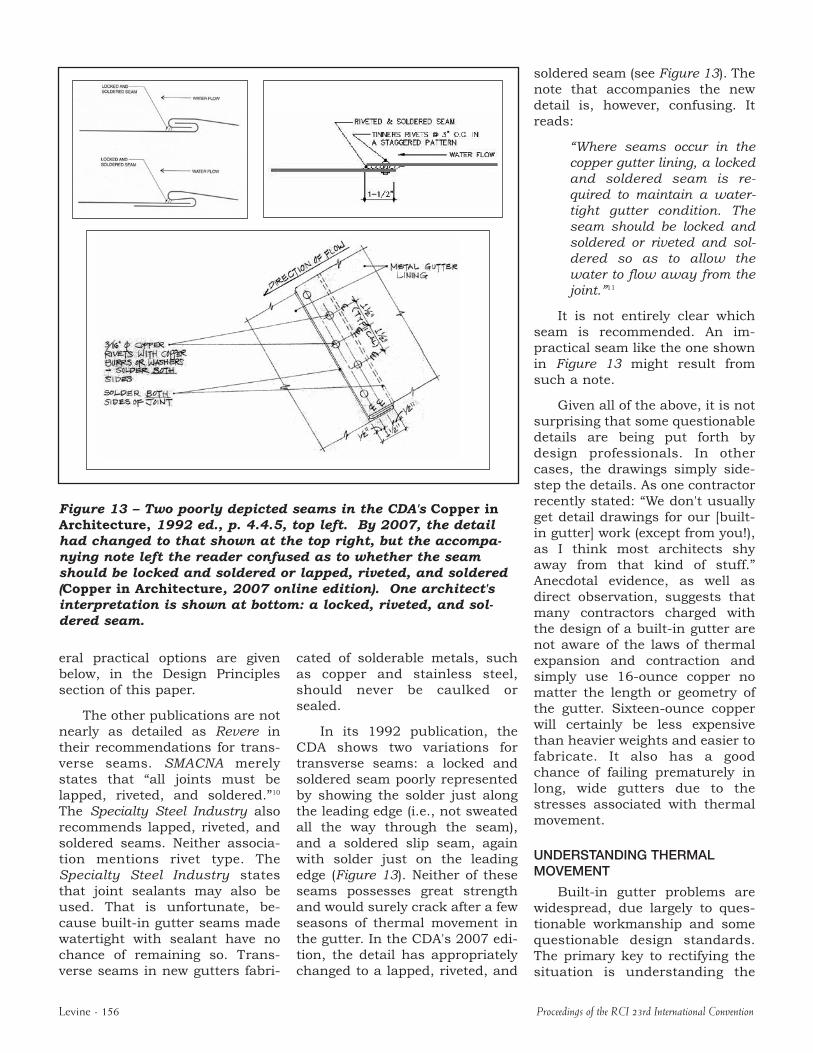