bulkheads and drains for high sandfill stopes
TRANSCRIPT
~ iRIIs959 t Bureau of Mines Report of Investigations/19B5
~
Bulkheads and Drains for High Sandfill Stopes
By R. l. Soderberg and R. A. Busch
UNITED STATES DEPARTMENT OF THE INTERIOR ~7t5~ c g; 0..<:- ~
MINES 75TH A ~

Report of Investigations
Bulkheads and Drains for High Sandfill Stapes
R. L Soderberg and R. A. Busch
UNITED Donald
BUREAU
DEPARTMENT OF THE INTERIOR Hodel, Secretary
MINES Robert C. Horton. Director

Library of Congress Cataloging in Publication Data:
Sodelberg, R. L
Bulkheads and drains for high sandfill s copes.
(Report of investigations / United States Department of the Interi or, Bureau o f Min es; 8959)
SUpt. o f Docs. no.: [28.23:8959.
1. Mine filling. 2. Mine drainage. 3. Scoping (Mining)-Safety mea s ures . 4. Rock bursts. I. Busch, R. A. (Richard A.). [I. Tirle. Ill. Series: Keport of investigation s (United States. Bureau of Mine s ) ; 8959.
TN23.U43 [TN292] 622" [622' .8] 85-600014

COtJTENTS
Ab s t rae t •••••••••••••••••• 0 •••••••••••• co ••••••••••••••••••••••••••••••••••••••
In t roduc tion. . . . . . . . . . . . . . . . . . . . . . . . . . . . . . . . . . . . . . . . . . . . . . . . . . . . ........ . Acknowledgments ...........................•....•...........•.....•............ Re search plan ................................................................ . Research equipment ........................................................... . Tailings test material ....................................................... . Filter and transition zones ••••••••••••••••••••••••••••••••••••••••••••••••••• Test procedures and results ........................................ . Research application to mine fill operations •••••••••••••••••••••••• Drainage calculations .....................•......................... Drain pipes ............................... . Gravel drain •••••••••••••••• : •••••••••••••• Filters ...................................................................... . Bulk head ..................................................................... . Decant ..•..................................................................... Conclusions and recommendations ••••••••••••
ILLUSTRATIONS
1. Plexiglass model showing gravel drain, sand filter, bulkhead, and
2. 3. 4.
5. 6. 7. 8. 9.
10. 11.
pressure cell .......................................................... . Original laboratory model •••••••••••••••••••••••••••••••••••••••••••••••• Test facility--14-in pipe, 15 ft long •••••••••••••••••••••••••••••••••••• Test facility--simulated stope bottom with drawpoint and crosscut with pressure cell in the bulkhead .......................................... .
Test facility--showing gauge arrangement ••••••••••••••••••••••••••••••••• Unclassified mill tailings used in most tests •••••••••••••••••••••••••••• Test results, days 1 to 7 •••••••••••••••••••••••••••••••••••••••••••••••• Test results, days 11 to 16 ••••••••••••••••••••••••••••••••••••••• ~ •••••• Cross section through drawpoint with perforated pipe, drain, filters, and decant pipe •....................................................... 0 ••••
Stope elevation--al ternate decants ••••••••••••••••••••••••••••••••••••••• Longitudinal section with perforated pipe, drain, filters, and decant
1 2 2 3 3 4 7 8
10 10 11 12 12 12 13 13
3 4 5
6 7 8 9 9
11 13
pipes. .. . .. .. ... . ... . . .... . ... ... ... . . . . . . .. .. . .. . . .. ... . .. .. . .. . . . .. .. . 14
l. 2.
TABLES
Gauge pressures with bottom drain closed ••••••••••••••••••••••••••••••••• Gauge pressures with bottom drain open •••••••••••••••••••••••••••••••••••
9 10

UNIT OF MEASURE ABBREVIATIONS USED IN THIS REPORT
cm/s centimeter per second in/h inch per hour
ft foot m meter
ft 3 /min cubic foot per minute mm millime ter
ft 3 /s cubic foot per second pet percent
gal/min gallon per minute psi pound per square inch
in-diam inch-diameter yr year

BULKHEADS AND DRAINS FOR HIGH SANDFILL
By R. L. Soderberg 1 and R. A. Busch 2
ABSTRACT
Large open s mined by vertical crater retreat or sublevel s are sometimes backfilled with uncemented sand to support the s walls and alleviate rock bursts. The failure of bulkheads in two different mines prompted a research project at the Bureau of Mines to prevent a recurrence of these failures. A series of laboratory tests with drains and sand filters was conducted to measure the bulkhead pressures when adequate was maintained. Results showed that bulkhead pressure was reduced to near zero while drains were in operation, as compared to full tatic pressure when drains were blocked or drainage was restricted. A relatively simple, • freedraining bulkhead was shown to be adequate.
neer (retired). neer.
Research Center, Bureau of Mines, Spokane, WA.

2
INTRODUCTION
The use of mill sand for fill-underground open has
been common for nearly 40 yr. With the advent of from sublevels or vertical crater retreat min-
these s may be as as 300 to 1,000 ft long, 50 to 150 ft wide, and 300 ft
To mine the pillars left when these bulk methods are used, or to pro-vide control, these stopes must be backfilled. Mill tailings are the most common materials available at a reasonable cost.
Two of bulkhead disasters are cited below. The information was obtained communication with the various mines; no reports or publications are available.
In the midforties, the of Howe Sound Co. of backfilling concrete bulkhead in a stope. This bulkhead without drains and in the walls to form a
Chelan Division this method
a reinforced raise below the was constructed
with hitches
to withstand the full pressure. The was to decant the water off the top of the fill. To this, percussion holes were drilled at 10-ft vertical intervals from the raise into the stope. The clear water was decanted from each hole until the sand reached that level. The hole was then blocked with a wood plug, and the water was allowed to rise to the next hole. A rock burst occurred in the which may have affected the the bulkhead. Eventually, static head became great enough to crack the bulkhead. The sand was under such pressure that it eroded a
hole and flowed into the mine workings. All the personnel were evacuated, but it took several months to clear the levels and the shaft.
the Hudson Bay and Co. Mine at Flin Manitoba,
had a bulkhead failure that flooded several levels and the shaft and caused the loss of one miner. A wood bulkhead had been and constructed.
was taken to prevent trouble. Wood box drains with burlap
in front of the bulkthe bulkhead to
tatic pressure buildup. Pressure gauges placed in the bulkheads no pressure and were later removed. Excess water was pumped off the of the fill after each pour, and total water into and out of the mine was monitored. Several wood, mousetrap drains the hydro-static head built up and the bulkhead failed, the mine.
A mine in Tennessee used 4-ft-thick concrete bulkheads with No. 6 reinforcing steel at 4-in centers, but had no drains to remove the water. Leaks the rock and around the bulkheads caused the operator to abandon the method and substitute loose rock backfill in the This fill was obtained from the surface and a borehole. To the inves 's knowledge, there have been no massive failures.
This Bureau of Mines involves the testing of bulkheads in the laboratory
fill and various combinations of filter materials. The report will indicate the and procedures used and the test results obtained.
ACKNOWLEDGMENTS
The authors are to the manage- Research Center personnel--Doug Piper, ment of Hudson and Smelting machinist, Mike Jones, engineering tech-Co. of Flin Manitoba, for permis- nician, and sian to reference their in this electronics technician--for report. thanks go to Spokane fabrication and instrumentation.

3
RESEARCH PLAN
The problem with high stope backfills is the excess hydrostatic pressure that can develop because of inadequate drainage. The downstream toe of earth dams and of some tailings dams employs blanket drains designed to discharge seepage water and effectively reduce the neutral stress in the dams. The same concept can be adapted to stope backfilling. The plan would include installation of perforated steel pipes covered with coarse gravel and protective filter combined
with a relatively light bulkhead in the crosscut near the drawpoint. A drain of this type would be positive, could be designed to remove all the water draining from the stope, and would be economical to construct. It would discharge clean water free of sand and would place little or no pressure on the bulkhead because the water pressure is reduced to atmospheric in the drain. Because the plan showed definite promise, a research project was designed to test the concept.
RESEARCH EQUIPMENT
During the intitial research on the bulkhead and drains, a 4-in-diam plastic pipe, 14 ft long, was placed upright against the laboratory wall to simulate the stope. A 4-in-diam plexiglass pipe, 12 in long, was attached to the bottom so it could be easily detached from the plastic pipe. A 2-1/8-in-diam plexiglass pipe, 4 in long, was cemented to the side of the larger plexiglass pipe perpendicular to its axis to simulate a crosscut to the drawpoint (figs. 1-2). The use of plexiglass for the bottom sections
enabled observation of the water exiting the fill.
A bulkhead sealed with an O-ring and containing a 25-psi pressure cell was used to measure the drained filter pressures below 3 psi. A second bulkhead with a 100-psi cell was used for the high-pressure tests. Two pressure gauges were installed on the vertical pipe used to simulate the stope, one at 10 in above t he drainage material and the other 36 in higher on the pipe. These gauges acted as checks on the pressure cell.
FIGURE 1. . Plexiglass model showing gravel drain, sand filter, bulkhead, and pressure cell.
4
4-in plasti c pipe
Bulkhead
0- r i n 9
Filter sand - ----+l Pressure cell
Gravel drain
Dr a i n
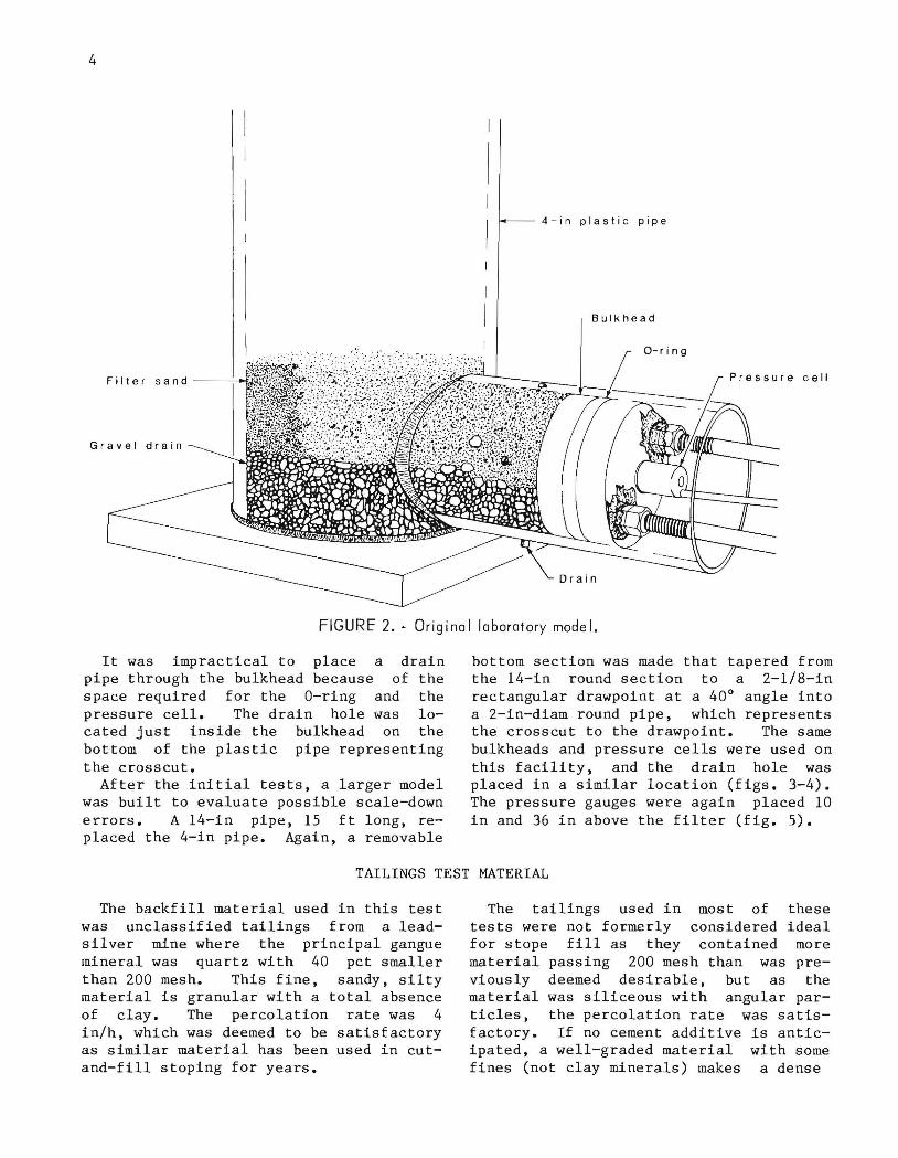
FIGURe 2. - Original laboratory model.
It was impractical to place a drain pipe through the bulkhead because of the space required for the O-ring and the pressure cell. The drain hole was located just inside the bulkhead on the bottom of the plastic pipe representing the crosscut.
After the initial tests, a larger model was built to evaluate possible scale-down errors. A 14-in pipe, 15 ft long, replaced the 4-in pipe. Again, a removable
bottom section was made that tapered from the 14-in round section to a 2-1/8-in rectangular drawpoint at a 40° angle into a 2-in-diam round pipe, which represents the crosscut to the drawpoint. The same bulkheads and pressure cells were used on this facility, and the drain hole was placed in a similar location (figs. 3-4). The pressure gauges were again placed 10 in and 36 in above the filter (fig. 5).
TAILINGS TEST MATERIAL
The backfill material used in this test was unclassified tailings from a leadsilver mine where the principal gangue mineral was quartz with 40 pct smaller than 200 mesh. This fine, sandy, silty material is granular with a total absence of clay. The percolation rate was 4 in/h, which was deemed to be satisfactory as similar material has been used in cutand-fill stoping for years.
The tailings used in most of these tests were not formerly considered ideal for stope fill as they contained more material passing 200 mesh than was previously deemed desirable, but as the material was siliceous with angular particles, the percolation rate was satisfactory. If no cement additive is anticipated, a well-graded material with some fines (not clay minerals) makes a dense

5
FIGURE 3.· Test facility-14-in pipe, 15 ft long.

6
FIGURE 4. - Test facility-simulated stope bottom with drawpoint and crosscut with pressure cell In
the bu I khead.

fill and is actually better coarser sand. The gradation of tailings, as used, is shown in The results of one test with
than a the total figure 5.
this tail-ings material, over a 16-day period, are shown in figur.es 5 and 6. Note that the bulkhead pressure scale has been de-
7
creased 10 times in order to show it on the same figure as the applied pressure.
The drain material is subrounded gravel, 2 to 4 mm in diameter. The filter is a quartz sand, grading from 0.6 mm to 0.09 mm, and conforms to proper filter criteria.
FILTER AND TRANSITION ZONES
A protective filter is any porous material that has openings small enough to prevent movement of soil into the drain and yet is more pervious than the soil it is protecting. Transition zones are also filters between a very fine and very coarse material where several different filter materials have to be used. Several of these transition zones or filter layers may be required, depending on the difference in grain size between the tailings and the drain materials.
Bulkh e ad a n d pr ess ure ce ll
Pr ess ure g a u ge
F i J Ja n d appli ed pr ess ur e
1---- 1 4 -in pipe . 1 5 f I J o ng
Pr ess ur e gauge
FIGURE 5 •• Test facility-showing gauge
arrangement.
To satisfy the criteria for filter materials, the following rules 3 should be applied:
1. The 15-pct size of the filter divided by the 85-pct size of the protected soil should be less than 5.
2. The 50-pct size of the filter divided by the 50-pct size of the protected soil should be less than 25.
3. The filter material should be smoothly graded; gap-graded materials should be avoided.
4. The 15-pct size of the filter divided by the 15-pct size of the protected soil should be greater than 5.
5. The filter should not contain more than 5 pct of particles, by weight, finer than the No. 200 sieve, and fines should be cohesionless.
6. The coefficient of uniforcrity of the filter should be between 5 and 20 to prevent segregation during placement.
Filters need not screen out all the particles of the tailings, only the coarsest 15 pct, or the DS5 size. These coarser particles (DS5 and larger) will collect over the filter openings and screen out the smaller particles. If soils are used as filters (such as transition zone and cobbles), the effective diameter of soil voids must be less than DS5 of the soil being filtered. Since effe~tive pore diameter is about onefifth of the D 15 size, the D 15 of the filter should be less than the DS5 of the soil. The filter must provide free drainage. Because the permeability coefficient varies as the square of the grain size, the ratio of permeabilities of over 20 to 1 can be secured by making the D I5 of the filter greater then five times the D15 of the soil.
3Cedergren, and Flow Nets.
H. R. Seepage, Drainage Wiley, 1967, 467 pp.

8
SEDIGRAPH-5000 A NAL YSIS
SCREEN ANALYSIS U S . St a ndard
S c reen an a lysis reading= 0
100 0
90 10 .. CD ..
80 CD C
en 20 ..
cg 0 - 70 - 30 (,) -(,) (,)
Q. 60 40 a.:
rn rn CJ 50 Z
50 CJ Z
-' 40 -' 60 -< < I- I--' 3 0 70 -' -' -' ~ 20 80 ~
10 90
0 100 '? ~ ~ ')t ...
~
GRAIN SI Z E, mm
FIGURE 6.· Unclassif ied mill tailings used In most tests.
TEST PROCEDURES AND RESULTS
The first step in setting up each test was to secure the bulkhead in the pipe simulating the crosscut at the proper distance from the drawpoint. The gravel blanket drain was placed on the bottom of the crosscut. The depth ranged in the series of tests from one-quarter to onehalf the crosscut height. The sand filter was placed on top of the gravel drain and extended up into the drawpoint. This filter material satisfied the criteria as previously outlined and was designed to prevent the tailings from penetrating the gravel drain. The tailings, at 60 pct solids by weight, were pumped into the top of the pipe (fig. 3).
When the drain was left open while placing the tailings, and when the pipe was full, the pressure cell in the bulkhead showed a pressure of 0.3 psi, the pressure gauge 10 in above the crosscut showed 1.0 psi, and the gauge 36 in
higher in the column indicated 0.7 psi. These low readings indicate the dynamic fluid pressures under drained conditions with no induced pressure, which are practically negligible. The bulkhead pressure is the lowest because it is downstream from the drain.
When the drain was closed during the filling of the stope, all gauges registered a pressure proportional to the height and the density of backfill slurry in place. To apply greater pressure on the backfill, simulating greater heights of fill, the pipe was capped and air or water pressure was applied. Pressure was applied in increments, and readings were taken on the pressure cell and the pressure gauges. As long as the sand was saturated, the pressure increases were relative at all measuring points (table 1). The maximum~ test pressure was 100 psi (figs. 7-8).

TABLE 1. - Gauge pressures with bottom drain closed, pounds per square inch
In- Bulk-duced Gauge Gauge head
Time air 1 2 pres- Remarks pres- sure sure cell
a.m. : 11:30 0 8 10 I Test p~pe
filled. 11 :40 ND ND ND ND Leaky
drain repair-ed.
11:45 11 20 23 20 11:50 20 30 32 30 11 :55 30 39 42 40
noon~
12:00 40 49 51 51 p.m. :
12:05 50 59 62 61 12:10 60 70 72 71 12:15 70 78 80 79 12:20 80 90 91 90 12:25 90 99 100 99 12:30 ND ND ND ND Drain
opened. 12 : 31 90 98 94 .6 ND Not determined.
NOTE.--Gauge 1 was 11 ft below the top of the 14-in pipe. Gauge 2 was 14 ft below the top of the 14-in pipe. The bulkhead pressure cell was reading slightly low.
1 10
100
90
'" ~ 80
ui a: 7 0 :;) (/)
8 0 (/)
UJ a:
50 0..
0 40 ~ -' 0.. 30 "-<{
2 0
1 0
KEY -- Pr es sure o n ce l l
I n bulkhea d
89 II 123 7 8 9 11 1 23 87891 1 1 2 3 676 9 11 123 6 7 6 9 11 1 2 10 12 10 12 10 12 10 12 10 12
DAY 1 D A Y 4 DA Y 5 DA Y 8 DA Y 7
FIGURE 7. - Test results, days 1 to 7.
10
'" ~ UJ a:
7 :;) (/)
(/)
6 UJ a: 0..
o <{
4 UJ I
"" ...J :;)
OJ
9
When the drain was opened, the pressure on the bulkhead dropped immediately to near zero, and the gauges located higher in the column maintained a dynamic pressure (table 2). The residual pressure on the bulkhead represents the earth pressure at rest (Ko). This pressure decreases as the distance from the brow of the drawpoint to the bulkhead increases because of the shear at the rock wall. In the tests conducted, the distance from the brow of the drawpoint to the bulkhead ranged from 1/2 to 1-1/2 times the c rosscut diameter, but the difference in pressure on the bulkhead was too small to measure.
This research indicates that in the test facility, with proper filters and drains installed and 60-pct-pulp-density tailings in place to a depth of about 15 ft, all the gauges register the hydrostatic head if the drain hole is closed during filling. These pressure gauge readings increase with the increase of air or water pressure applied at the top of the column. When the drain is opened, the bulkhead pressure drops immediately to less than 2 psi (table 1).
In the test situation where the drains are open when the 60-pct tailings slurry is pumped in, the bulkhead cell pressure did not register above 0.6 ps i . When the applied pressure was raised to 100 psi, the bulkhead cell pressure occasionally
KEY 80 -- Pr es sure on c ell in b ul k h ea d
- App li ed pr es su r e
'" Q
7 0
w 6 0 a: :;)
~ 5 0 w a: 0.. 40
o ~ ...J 3 0 0.. 0.. <{ 20
10
~--r
'" Q
6 W a: :::l (f)
5 (f) w a: 0..
o <{
w 3 I
"" ...J :::>
2 m
LLLLLL~~~-LLL~~~~~LL~ __ ~~~ O
6 1 6 9 , 01112 67691011 12 1 23 6 789 10 111 2 1 2 141 5 1 6
DAY 1 1 DAY 1 2 DA Y 13 DA Y
FIGURE 8. - Test results, days 11 to 16.

10
increased to a maximum of 1.5 psi. The pressure applied at the top of the column has very little effect on the pressure registered against the bulkhead as long as the drains are open. The highest ever recorded was 1.5 psi when the applied pressure was 100 psi; normally, the variation is only 0.3 psi either way. In actual operations in a mine, the drains would never be closed. They were closed in this test facility only to check the functioning of the load cell by comparing pressures with the two dial gauges. As long as the drains were designed properly with sufficient cross-sectional area so that their capacity was much greater than the flow from the stope, there was little pressure against the bulkhead (figs. 7-8). A drain such as this, composed of hard, chemically resistant rock, is much better than filter cloth because there is no deterioration or loss of filter capacity with time.
TABLE 2. - Gauge prssures with bottom drain open, pounds per square inch
Induced Gauge Gauge Bulkhead Date water 1 2 pressure
pressure cell 5/24 59 62 63 0.14 5/25 35 40 41 .13 5/26 60 66 68 .16 5/27 60 63 66 .05 5/28 60 65 66 .02 6/1 60 66 68 .21 6/2 58 65 68 .12 6/3 58 65 69 .05
NOTE.--Gauge 1 was 11 ft below the top of the 14-in pipe. Gauge 2 was 14 ft below the top of the 14-in pipe. The water pressure was applied continuously, and the pressure readings reflect the dynamic head.
RESEARCH APPLICATION TO MINE FILL OPERATIONS
The results of this research can be applied directly to any stope-filling operations where mill tailings, or surface sand with or without cement, are used and placed as a high-density slurry. In this situation, a large portion of the excess water can be decanted off, but the main problem is to control the water that seeps through the fill. Unless adequate drains are provided, this can cause high hydrostatic pressures against the retaining bulkhead.
A conceptual design, applying this research to an underground mine fill, is presented. Since the characteristics of each mine vary, the actual design must be based upon site conditions. The following steps or procedures may apply.
To prepare a stope for fill, a few simple steps should be followed. The drawpoint should be thoroughly cleaned up to where the cone starts, even to the
extent of washing it somewhat to remove material that might wash down when the first slurry is placed in the stope. Some of this material may be detrimental to the filter. The easiest way to place the filter sand may be from above, and care should be exercised to prevent contamination by material in the stope.
The crosscut leading to the drawpoint should also be cleaned to a smooth level floor, but not necessarily removing all the accumulated fine material. The bulkhead should be placed at a minimum distance of 1-1/2 times the crosscut height outside the brow of the drawpoint. Hitches should be cut into both ribs and the floor of the crosscut to anchor the bulkhead. A hitch in the back of the crosscut is optional. The perforated pipes, gravel drain, filters, bulkhead, and decant pipes should then be installed in preparation for filling (fig. 9).
DRAINAGE CALCULATIONS
To design the drain required, the anticipated flow must be calculated. The grain size of the tailings to be used as fill will determine the grain size of the
finest filter sand necessary between the tailings and the gravel drain. The permeability (k) of this filter sand must then be determined by laboratory tests.
o \) 0
o
o 0 •
o 0 • o d 0 0
o 0
o •
o 0 0 00° 000 COO 0
o 00 0 0
o
Decant pipe with filter cloth
, r ' " ~ I I' "
coarse sand
'- '-
, ' , _ , '-.' t (
Timber
1-in gap
,- --- r'_ - , ,~ '\ ~~ _ " { ( (r--~ __ F i I t err - ,r (( ;- ~ , ( (.r- ,', I--~~
'r (r-( ( , I .... / r r r I - (
.0 000 °0°
OOoO~O.o Oed
zone • 0 •• ~ ., •
• 0 • 0 o • 0
• 0 0 • 0 0 1-4---- Bulkhead
o 0 o COO o
to 2 in 0 o " 0 0
Perforated pipes
. .2+---- Cone rete( op t i 0 na I)
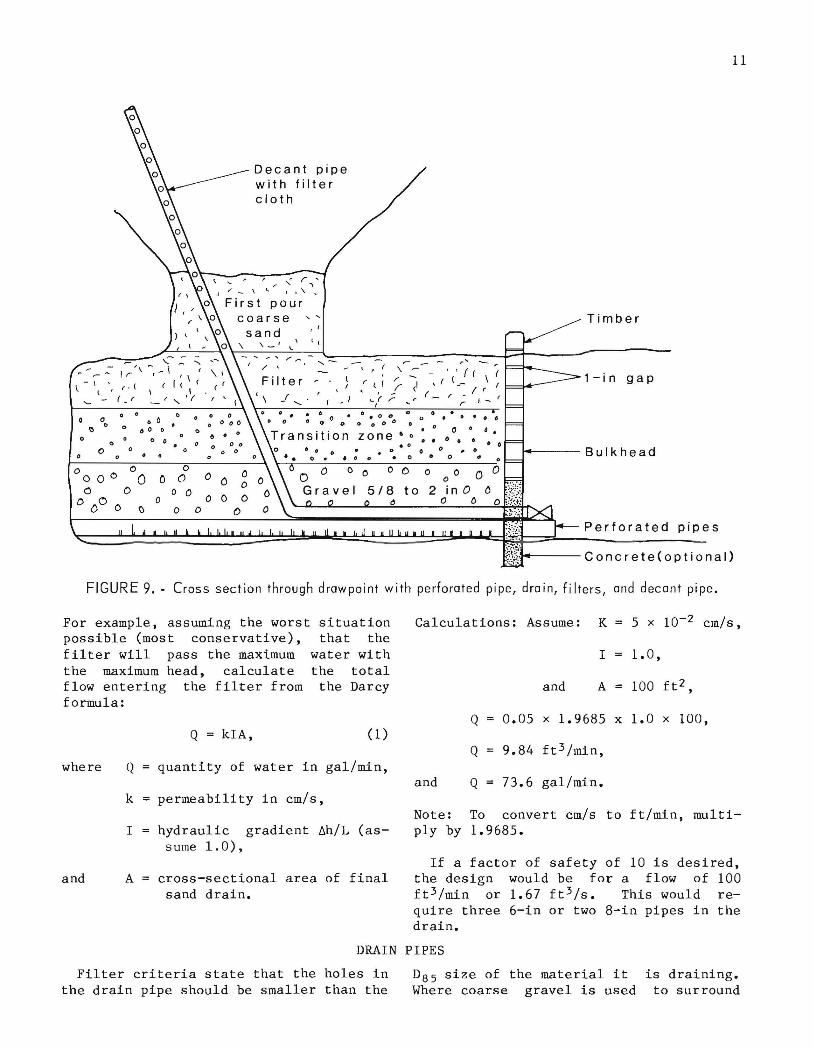
FIGURE 9. - Cross section through drawpoint with perforated pipe, dra in, filters, and decant pipe.
11
For example, assuming the worst situation possible (most conservative), that the filter will pass the maximum water with the maximum head, calculate the total flow entering the filter from the Darcy formula:
Calculations: Assume: K 5 x 10⁻² cm/s,
Q = kIA, (1)
where Q quantity of water in gal/min,
k permeability in cm/s,
I hydraulic gradient llh/L (as-s ume 1.0),
and A cross-sectional area of final sand drain.
I 1. 0 ,
and A 100 ft2,
Q 0.05 x 1. 9685 x 1.0 x 100,
Q 9.84 ft 3 /min,
and Q 73.6 gal/min.
Note: To convert cm/s to ft/min, multi-ply by 1.9685.
If a factor of safety of 10 is desired, the design would be for a f l ow of 100 ft 3 /min or 1.67 ft 3 /s. This would require three 6-in or two 8-in pipes in the drain.
DRAIN PIPES
Filter criteria state that the holes in the drain pipe should be smaller than the
D85 size of the material it Where coarse gravel is used
is draining. to surround

12
the perforated pipe, this criterion does not apply. When perforated pipe is not available, slots may be cut into 6- or 8-in pipe, but the slots should be no more than 1/2 in wide, assuming the gravel size is +5/8 in. Only the bottom onequarter of the pipe is to be perforated, with the slots at right angles to the pipe and spaced at 3-in centers along
that portion of the pipe in the area to be drained. Slots may be cut parallel to the pipe axis, providing the same area of openings. It is important that a surplus of slots be cut to ensure that the water can flow freely into the pipe. The cross-sectional area of the slots should be three to four times the crosssectional area of the pipe c
GRAVEL DRAIN
The coarse drain material can be either rounded river gravel or crushed rock and should be well graded from 5/8- to 2-in size. A siliceous rock is preferable, and mandatory if the water is acidic, so there is no chemical reaction to deteriorate the material. It should also have a high strength to resist crushing. A good
hard limestone is acceptable if acid water is not a problem.
A bed of gravel 6 in thick should be spread on the floor of the crosscut beneath the drain pipes and extend above the pipes to a total depth of gravel of about 3 ft; this gravel can be placed with a front-end loader.
FILTERS
On top of the coarse gravel, several layers of filter material, each decreasing in size and conforming to the filter criteria, will be necessary to prevent the tailings from washing into the gravel, but yet allow a free flow of water.
These transition zone filter layers can also be placed with a front-end loader. Some handwork would probably be necessary to spread and level the material.
The final filter sand would have to be placed pneumatically through the bulkhead, or hydraulically through the fill pipes, whichever is most convenient. If pneumatically placed, the sand will be very loose. This must be taken into consideration when depositing the filter so that when it becomes saturated and compacted, there will be ample sand to fill the area. The first pour into the stope should be the same filter sand and extend at least 3 ft above the brow of the draw hole. This is a precaution to ensure complete filling of the crosscut and a
portion of the draw hole prior to tailings deposition (fig. 9). These filters must conform to filter criteria and be designed to allow water to flow freely from the tailings in the stope fill through the filter and transition zone into the gravel and drain pipe without carrying fines or clogging the filter. After the initial fill, the water will wash all the dirt and fine sand from the sand and gravel drain material. After this, there should be only clean water exiting the drain. The permeability value for each material from the tailings to the gravel should be increased by a factor of 10 or more. The grain size of the filter is governed by the grain size of the tailings used for fill. Successive filter layers make the transition to the gravel surrounding the drain pipes. Specifications for choosing the proper filter gradation are outlined in the "Filter and Transition Zone," section of this report.
BULKHEAD
The bulkhead should be constructed of reinforced concrete, hitched into the walls and floor, and high enough to extend 2 ft above the top of the drain pipes. This will direct all the water to
the pipes, where it can be disposed of as desired. Above the concrete, square tim-' bers are laid horizontally and supported by vertical posts. Since this portion of the bulkhead should not be watertight,

these timbers should have a gap that will restrain the gravel but allow the free flow of water. If the drain is designed properly and performs as planned, the water should never get above the top of
13
the concrete. To keep the transition and filter sand from going through the bulkhead, the gravel should be placed against the bulkhead up to the top of the crosscut (fig. 9).
DECANT
The clear water from the top of a stope fill may be pumped off after the fines have settled. However, this is probably the most unsatisfactory way to remove the water because it requires access to the stope and personnel to place and operate the pumps. There also exists the probability of pumping dirty water.
The vertical crater retreat method of ore breaking does not require a raise in the pillar beside the stope being filled. However, if a raise is available, horizontal holes of any convenient diameter from 2 to 4 in can be drilled from the raise into the end of the stope for decanting the water. The spacing between holes would be optional (fig. 10).
A preferred method of removing the water from the top of the fill is to install several decant pipes from the drawpoint up to an access drift in the pillar (fig. 11). The size of the pipes depends on the size of the stope and the filling rate. These pipes should have holes
spaced at 6-in centers from the top down to the sand filter . Below the filter and out through the bulkhead ~ the pipes should be solid. Outside the bulkhead, a valve should be ins t alled as a pre caution in case the pipe is broken by falling rock. The valve could then be closed to prevent tailings from being discharged. The decant pipe should be covered with a filter cloth to prevent any of the fine sand from entering it. A variety of filter cloths should be tested to determine which would best prevent the infiltration of fines into the decant pipe. Using a decant pipe to remove the water from the top of the fill presents several advantages. There would never be a large depth of water in the stope at any time, water removal starts as soon as filling starts, water clarification is not neces sary before removal, no work force is required, and filling can be continuous if desired.
CONCLUSIONS AND RECOMMENDATIONS
This research project demonstrated the importance of filter layers and drains to relieve the pressure on a bulkhead that is designed to retain an unconsolidated sandfill. The reduced pressure on the bulkhead when the drains were operating increased the integrity of the bulkhead and the safety of the simulated mine.
It is recommended that mines filling large stopes with mill tailings consider using the blanket drains and bulkhead concept as outlined in this report. Attempts to permanently seal these high stopes with reinforced concrete are extremely dangerous, and the practice should be stopped. Traditionally, the criterion for sandfill was to have a percolation rate of 3 to 4 in/h. This would be a relatively clean sand with amount of fines to act as a Without sulfides that oxidize and
a small binder: act as
a cementing action, or compaction from
squeezing ground, tendency to run.
I I I I I I
clean sand may have a By leaving more of the
Deca nt p i pe wi I h f il ter c I 0 I h
---1- -- J_i __ _ J 3 - ;n hOles,------l
a l terna l e decan t
" . // , ./
' ~ ( I I
/
/ /
/
FIGURE 10. - Stope elevation-a Iternate decants.
14
() 0 0
Decant pipe with filter cloth
/ ,... ___ First pour,
coarse sand
Filter
Transition zone
o ....... ---Gravel, 5/8 to 2 in
Perforated pipe
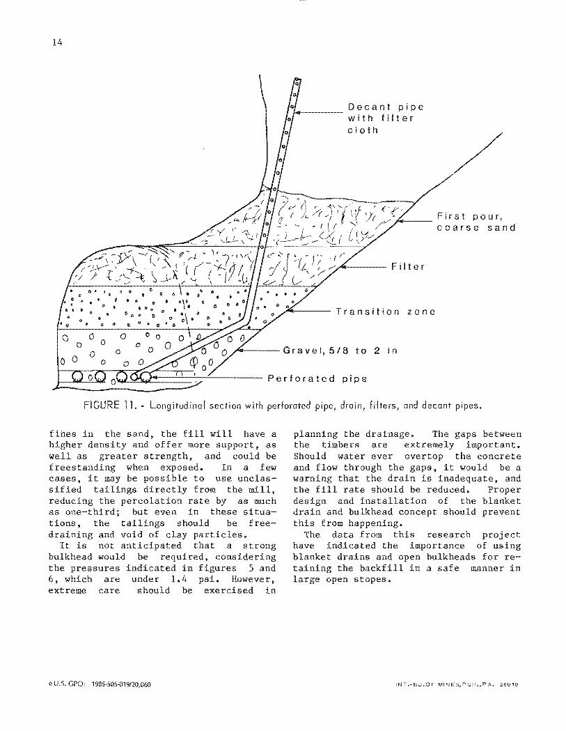
CURE 11. • Longitudina[ section with perforated pipe, drain, fH and decant pipes.
the sand, the fill will and offer more
st and
have a , as
could be frees when In a few cases, it may be possible to use unclassified tailings directly from the mill,
the rate by as much as one-third; but even in these situations. the should be free
and void of clay particles. It is not ant that a s
bulkhead would be , considering the pressures 5 and 6, which are under psi. However, extreme care should be exercised in
':\-U.S. GPO: 1985-505-019/20,060
the The gaps between the timbers are extremely Should water ever overtop the concrete and flow through the gaps, it would be a warning that the drain is the fill rate should be reduced. design and installation of the blanket drain and bulkhead should this from happening.
The data from this research have indicated the blanket drains and open bulkheads for re
the backfill in a safe manner in
INT.-BU.OF MINES,PGH.,PA. 28010