open stopes and support empirical design
TRANSCRIPT
TA
412
3–
Sta
bil
ity
of
Un
der
gro
un
d E
xcav
atio
ns
06
OPEN STOPES AND SUPPORT EMPIRICAL DESIGN
Ridho K. Wattimena
TA
412
3–
Sta
bil
ity
of
Un
der
gro
un
d E
xcav
atio
ns
06
INTRODUCTION

@RKW
TA
412
3–
Sta
bil
ity
of
Un
der
gro
un
d E
xcav
atio
ns
06
Introduction
❖ RMR and Q were developed from a database composed primarily of civil engineering tunnels.
❖ The recommendations derived from the systems often results in conservative designs for large temporary or non-entry mining excavations
❖ These limited access areas can be designed as temporary structures and in the case of non-entry stopes, can tolerate limited local fallout of small rock blocks provided that dilution is minimised and overall stability is maintained →A more economical design suitable for mining (Hutchinson and Diederichs, 1996).
TA
412
3–
Sta
bil
ity
of
Un
der
gro
un
d E
xcav
atio
ns
06
MATHEW’S STABILITY GRAPH METHOD
@RKW
TA
412
3–
Sta
bil
ity
of
Un
der
gro
un
d E
xcav
atio
ns
06
Introduction
❖ Mathews et al. (1980) proposed an empirical method for the dimensioning of open stopes based on Q’ and on three factors accounting for stress, structural orientation, and gravity effects.
❖ The method is used to dimension each face of the stopeseparately based on a combination of these three factors and on the hydraulic radius (surface area/perimeter) HRof the face.

@RKW
TA
412
3–
Sta
bil
ity
of
Un
der
gro
un
d E
xcav
atio
ns
06
Stability Number N
N = Q’ x A x B x C
Q’ = (RQD/Jn) x (Jr/Ja)
A is a measure of the ratio of intact rock strength to induced stress
B is a measure of the relative difference between the dips of the stope surface and the critical joint sets.
C reflects the fact that the orientation of the stopeinfluences its stability.

@RKW
TA
412
3–
Sta
bil
ity
of
Un
der
gro
un
d E
xcav
atio
ns
06
(Mathews et al., 1980)

@RKW
TA
412
3–
Sta
bil
ity
of
Un
der
gro
un
d E
xcav
atio
ns
06
(Mathews et al., 1980)

TA
412
3–
Sta
bil
ity
of
Un
der
gro
un
d E
xcav
atio
ns
06
MODIFIED STABILITY GRAPH METHOD
@RKW
TA
412
3–
Sta
bil
ity
of
Un
der
gro
un
d E
xcav
atio
ns
06
Introduction
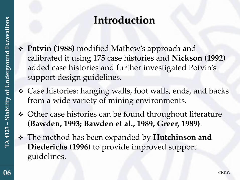
❖ Potvin (1988) modified Mathew’s approach and calibrated it using 175 case histories and Nickson (1992)added case histories and further investigated Potvin’ssupport design guidelines.
❖ Case histories: hanging walls, foot walls, ends, and backs from a wide variety of mining environments.
❖ Other case histories can be found throughout literature (Bawden, 1993; Bawden et al., 1989, Greer, 1989).
❖ The method has been expanded by Hutchinson and Diederichs (1996) to provide improved support guidelines.

@RKW
TA
412
3–
Sta
bil
ity
of
Un
der
gro
un
d E
xcav
atio
ns
06
Modified Stability Number, N’
❖ The classification of the rock mass and of the excavation problem is accomplished in the Modified Stability Graph through the use of the Modified Stability Number, N’(Potvin, 1988; Potvin and Milne, 1992; Bawden, 1993).
❖ N’ is similar to N proposed by Mathews at al. (1981) but has different factor weightings.
❖ Canadian mines use N’ and Australian mines use N (Hutchinson and Diederichs, 1996).
❖ This method has been referred to as the Potvin Method, the Mathews/Potvin Method, the Modified Stability Graph Method, and the Stability Graph Method.

@RKW
TA
412
3–
Sta
bil
ity
of
Un
der
gro
un
d E
xcav
atio
ns
06
Modified Stability Number, N’
N’ = Q’ x A x B x C
Q’ = (RQD/Jn) x (Jr/Ja)
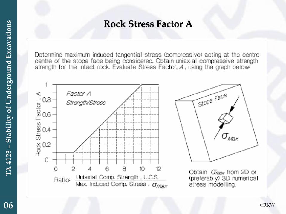
A is a measure of the ratio of intact rock strength to induced stress
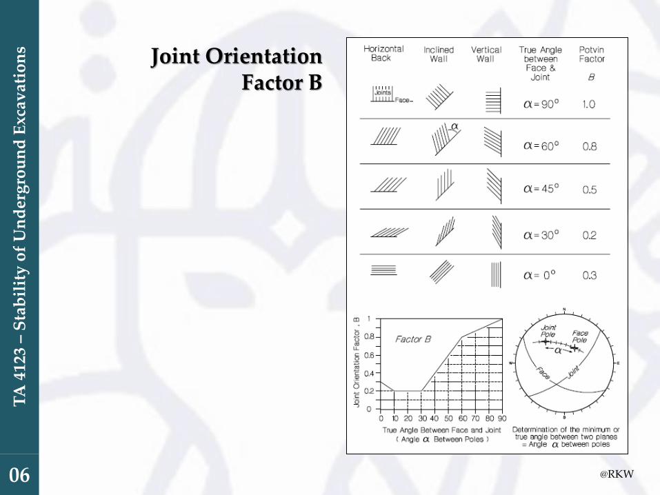
B is a measure of the relative orientation of dominant jointing with respect to the excavation surface.
C is a measure of the influence of gravity on the stability of the face being considered.
@RKW
TA
412
3–
Sta
bil
ity
of
Un
der
gro
un
d E
xcav
atio
ns
06
Rock Stress Factor A
@RKW
TA
412
3–
Sta
bil
ity
of
Un
der
gro
un
d E
xcav
atio
ns
06
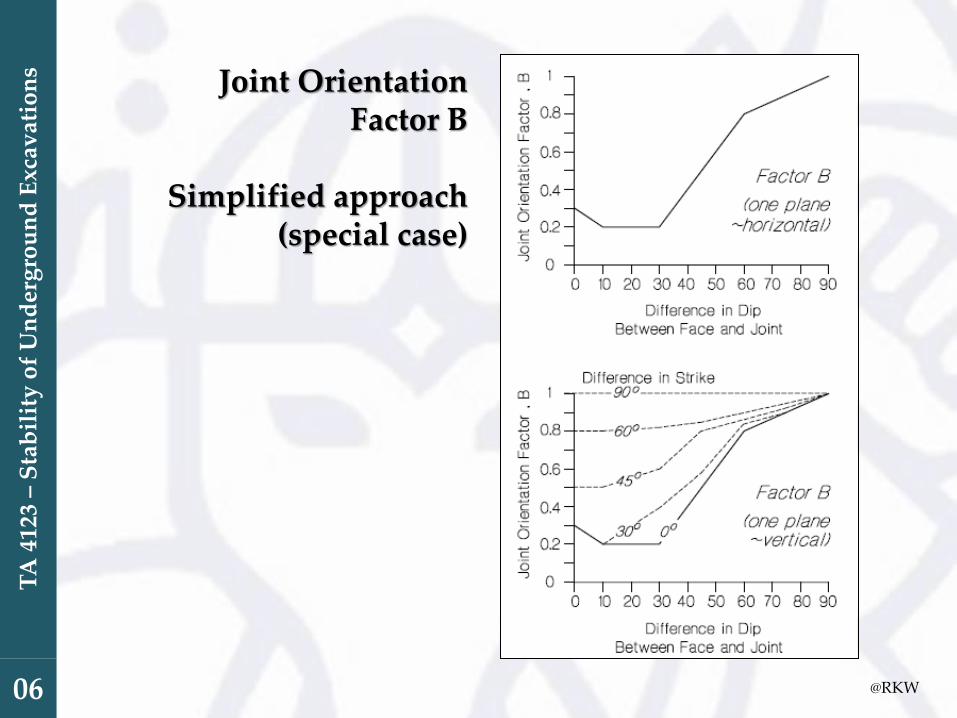
Joint Orientation Factor B
@RKW
TA
412
3–
Sta
bil
ity
of
Un
der
gro
un
d E
xcav
atio
ns
06
Joint Orientation Factor B
Simplified approach(special case)

@RKW
TA
412
3–
Sta
bil
ity
of
Un
der
gro
un
d E
xcav
atio
ns
06
Gravity Adjustment Factor C
@RKW
TA
412
3–
Sta
bil
ity
of
Un
der
gro
un
d E
xcav
atio
ns
06

@RKW
TA
412
3–
Sta
bil
ity
of
Un
der
gro
un
d E
xcav
atio
ns
06

@RKW
TA
412
3–
Sta
bil
ity
of
Un
der
gro
un
d E
xcav
atio
ns
06
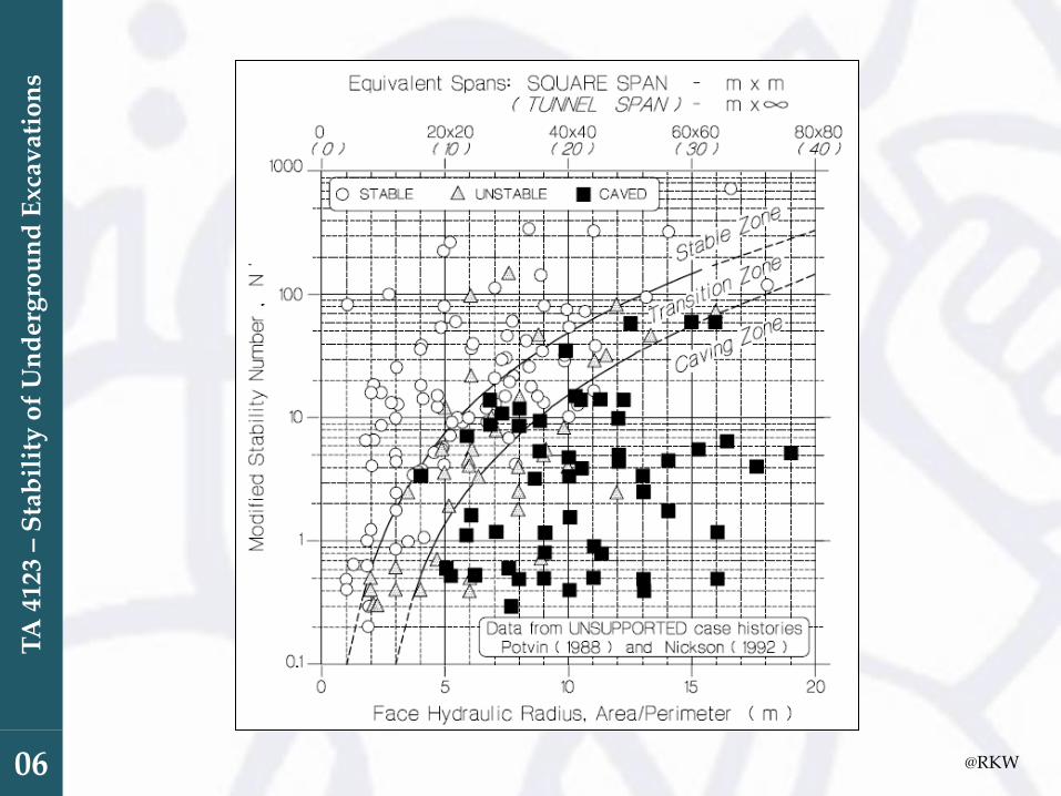
Stope and SupportDesign Zones
(Hutchinson and Diederichs, 1996)
@RKW
TA
412
3–
Sta
bil
ity
of
Un
der
gro
un
d E
xcav
atio
ns
06
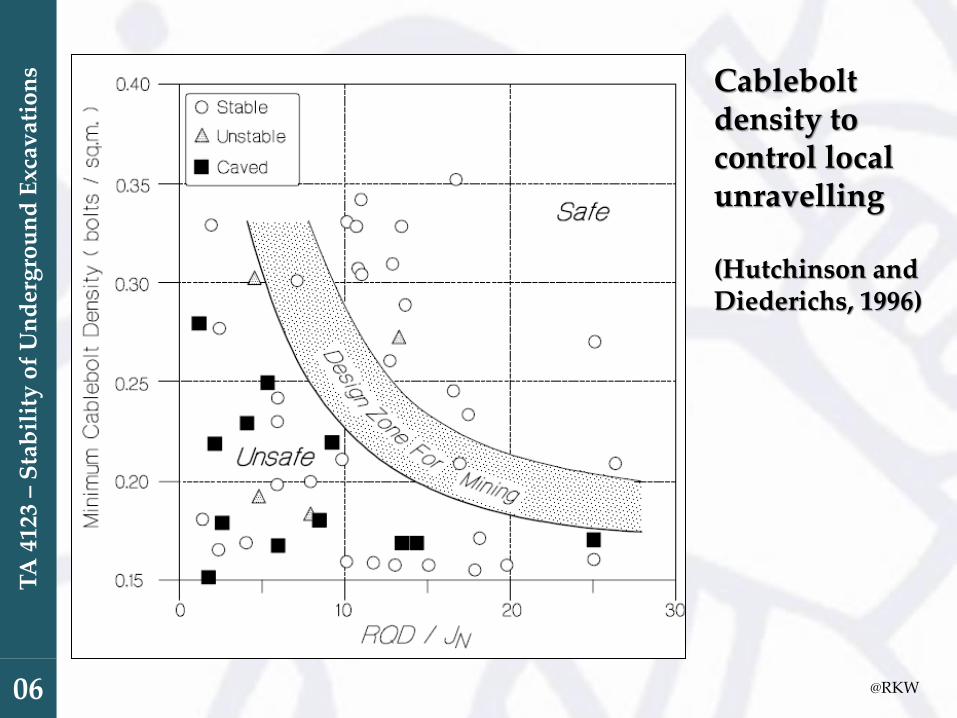
Cableboltdensity to control local unravelling
(Hutchinson and Diederichs, 1996)

@RKW
TA
412
3–
Sta
bil
ity
of
Un
der
gro
un
d E
xcav
atio
ns
06
Cableboltspacing and density for overall stopeface stability
(Hutchinson and Diederichs, 1996)

@RKW
TA
412
3–
Sta
bil
ity
of
Un
der
gro
un
d E
xcav
atio
ns
06
Five design zones for cable support of open stopes(Hutchinson and Diederichs, 1996)

@RKW
TA
412
3–
Sta
bil
ity
of
Un
der
gro
un
d E
xcav
atio
ns
06
(Hutchinson and Diederichs, 1996)

@RKW
TA
412
3–
Sta
bil
ity
of
Un
der
gro
un
d E
xcav
atio
ns
06
(Hutchinson and Diederichs, 1996)

@RKW
TA
412
3–
Sta
bil
ity
of
Un
der
gro
un
d E
xcav
atio
ns
06
(Hutchinson and Diederichs, 1996)

TA
412
3–
Sta
bil
ity
of
Un
der
gro
un
d E
xcav
atio
ns
06
EXTENDED MATHEW’S STABILITY GRAPH METHOD
@RKW
TA
412
3–
Sta
bil
ity
of
Un
der
gro
un
d E
xcav
atio
ns
06
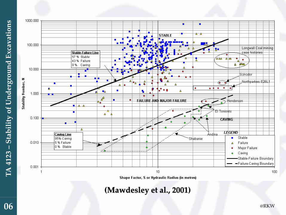
(Mawdesley et al., 2001)

THANK YOU