business practice manual for direct telemetry - … · iso business practice manual bpm for direct...
TRANSCRIPT

Business Practice Manual for
Direct Telemetry
Version 11.0
Revised: May 2, 2018

ISO Business Practice Manual BPM for Direct Telemetry
Version 11 Revised: 05/02/18 Page 2 of 110
Approval History
Approval Date : August 2, 2011
Effective Date : August 2, 2011
BPM Owner : Benik Der-Gevorgian
BPM Owner’s Title : Director, Market Services
Revision History
Version PRR Date Description
11.0 1054 05/02/2018
Removed ECN requirement for resources 400MW or
greater. Clarified maximum of 1200MW per connection
aggregating up to 25 resources. Consolidated
descriptions of real-time communications options into a
single section (5.3). Moved prior section 14 (ISO
Security) into section 4.4 to consolidate all security
topics under section 4 (Communications), including PKI
and ECN agreements and Connected Entity Service
Guides. Recharacterized RIG as any Real-Time Device
that can meet ISO functional, operational, and security
objectives. Added Dispersive™ CISDN communications
option. Added table of acronyms. Added table of
exhibits, figures, and diagrams. Modified multiple
diagrams. Non-Spinning Reserve Logic and Testing
(previously section 11). Removed redundant
Communication Technical Principles (previous section
13.4).
10 942 01/05/2017
Minor edits to section 3.2.2.1, changes to Section 6.7
DNP3 Variation type, 7.1 Point Matrix. In section 10.7
and 10.12 email address is updated. New section 10.9
RIG data validation is added. 10.12 RIG Generation
Acceptance test and 10.13 Final RIG Documentation
sections has been removed. Changes to 17.2.2 UCON

ISO Business Practice Manual BPM for Direct Telemetry
Version 11 Revised: 05/02/18 Page 3 of 110
Version PRR Date Description
definition. New section 17.5 Battery point definitions are
added.
9 895 3/10/2016
PRR 895 - Changes to Section 6.2.2 and 6.2.3 regarding PDR requirements. Change to Section 6.9 to update EIR RIG limit to 1200MW. Change to Section 12.4 to include SPIN Reserve Testing. Complete replacement of Section 14 to provide updated PDR Direct Telemetry Requirements.
8 832 5/29/2015 PRR 832 – Changes to Section 6.2.2 to add language regarding PDR Timing Requirements.
7 821 3/26/2015
PRR 821 - Added deadline for Wind/Solar site information form to paragraphs 13.4.2 and 13.5.4. Corrected reference to solar in paragraph 13.5.4. Removed Tables 13.4.2 and 13.5.4. Updated link for Network Connectivity Security Requirements and ECN Agreement in Section 10.6.
6 770 8/06/2014
Added clarifying language and site information form links
to section 13 Eligible Intermittent Resources (EIR),
subsections 13.1 to 13.5 and combined sections 13.6
with 13.5. Added updated language to section 10. FNM
Database Process and RIG Installation
5 726 4/03/2014
Added language to section 6.10 exempting DRP’s from
the RIG aggregation location limitation in the provision of
real-time telemetry data for Proxy Demand Resources
(PDR) (PRR 726)
4 719/725 3/21/2014
Added clarifying language indicating that Reliability
Demand Response Resources (RDRR) are not required
to provide telemetry and therefore exempt from direct
telemetry requirements to section 2.1 (PRR 725)
3 633 11/14/2012 Removal of the Full Network Model time line guide and
changes to EIR less than 10MW.

ISO Business Practice Manual BPM for Direct Telemetry
Version 11 Revised: 05/02/18 Page 4 of 110
Version PRR Date Description
2
489 12/14/2011
Added requirement for data quality flag propagation as
new Section 6.8, added requirement for preliminary
revenue metering package to Section 10.2, removed
unnecessary definitions from Section 4, and made
changes to ISP circuit exceptions in Section 5.3 per
BPM PRR 489. Effective Date 12/01/11.
1
8/02/2011 Initial BPM submittal document

ISO Business Practice Manual BPM for Direct Telemetry
Version 11 Revised: 05/02/18 Page 5 of 110
TABLE OF CONTENTS
1. Introduction ...................................................................................................................... 16
1.1 Purpose of ISO Business Practice Manuals .............................................................. 16
1.2 Purpose of This Business Practice Manual ............................................................... 16
1.3 Organization of This Business Practice Manual ........................................................ 16
1.4 References ............................................................................................................... 17
2. ISO Direct Telemetry ........................................................................................................ 20
2.1 Direct Telemetry Process .......................................................................................... 20
2.2 Energy Communications Network (ECN) ..................... Error! Bookmark not defined.
2.3 Connections over the Public Internet ........................... Error! Bookmark not defined.
2.4 Telemetry Standards Overview .................................... Error! Bookmark not defined.
2.5 Real-Time Device Defined ........................................................................................ 20
2.5.1 Remote Intelligence Gateway (RIG) Historically ............................................ 21
2.5.2 Data Processing Gateway (DPG) Deprecated ............................................... 21
2.5.3 RIG Recharacterized as Real-Time Device ................................................... 21
2.6 Installation and Validation of Direct Telemetry .......................................................... 22
2.7 Flow of Real-Time Data ............................................................................................ 23
3. ISO Responsibilities ........................................................................................................ 25
3.1 Overview of ISO Responsibilities .............................................................................. 25
3.2 Exceptions to Direct Telemetry ................................................................................. 25
3.3 Direct Telemetry Validation ....................................................................................... 25
3.3.1 Overview of Telemetry Installation Validation Process .................................. 26
3.3.2 ISO Certification Responsibilities ................................................................... 28
3.3.3 Documentation Requirements ....................................................................... 28
3.3.4 ISO Review of Documentation....................................................................... 30
4. Communications .............................................................................................................. 31
4.1 Overview of Communications Objectives .................................................................. 31
4.2 Choice of Connection Methods ................................................................................. 31

ISO Business Practice Manual BPM for Direct Telemetry
Version 11 Revised: 05/02/18 Page 6 of 110
4.3 Communication Context Diagram ............................................................................. 32
4.4 Main Communication Options ................................................................................... 34
4.5 Detailed Communication Options .............................................................................. 34
4.6 Ruggedized Gateway Available ................................................................................ 36
4.7 ISO Security for Direct Telemetry .............................................................................. 37
4.7.1 Data Confidentiality ....................................................................................... 37
4.7.2 Network Security Principles and Best Practices ............................................ 37
4.7.3 Communication Security Characteristics ....................................................... 38
4.7.4 Communication Security Protocols ................................................................ 39
4.7.5 Communication and ECN Agreements .......................................................... 40
4.7.6 Connected Entity Service Guides .................................................................. 41
4.8 Reliability .................................................................................................................. 42
4.8.1 Redundant Circuits ........................................................................................ 42
4.8.2 Data Validation .............................................................................................. 42
4.8.3 Voice Communications .................................................................................. 42
4.8.4 Communications During Telemetry Failure .................................................... 42
5. Operational Telemetry Requirements ............................................................................. 43
5.1 Unit Telemetry Visibility ............................................................................................. 43
5.2 Performance Monitoring ............................................................................................ 43
5.2.1 Direct Telemetry Timing Requirements ......................................................... 43
5.2.2 PDR Timing Requirements ............................................................................ 44
5.2.3 PDR Reading Requirements ......................................................................... 45
5.3 ISO Real-Time Communication Technical Design Options ....................................... 45
5.3.1 Functional Components of Real-Time Communication Options ..................... 46
5.3.2 Transport Options.......................................................................................... 47
5.3.3 Transport Conceptual Diagrams .................................................................... 47
5.3.4 Direct Telemetry Hardware Options .............................................................. 52
5.4 ISO EMS Interrogations ............................................................................................ 56

ISO Business Practice Manual BPM for Direct Telemetry
Version 11 Revised: 05/02/18 Page 7 of 110
5.5 DNP3 Object and Variation Types for Real-Time Device Responses ........................ 57
5.6 Quality Flag Propagation to DNP3 ............................................................................ 57
5.7 Maximum MW Real-Time Device Limitation .............................................................. 58
5.8 Real-Time Device Location Requirements ................................................................ 59
5.9 Real-Time Device Market Resource Limitation ......................................................... 59
5.10 Cost Responsibility ................................................................................................... 59
6. Telemetry Data Points List .............................................................................................. 60
6.1 Point Matrix ............................................................................................................... 60
6.2 Analog and Digital Notes .......................................................................................... 67
7. Availability and Maintenance .......................................................................................... 68
7.1 ISO Reliability Requirements .................................................................................... 68
7.2 ISO-Controlled Grid Operation and Market Availability Requirement ........................ 68
7.3 Real-Time Device Operation and Maintenance ......................................................... 69
7.3.1 Coordination of Changes to the Real-Time Device ........................................ 69
7.3.2 Database Configuration and Management Affecting the ISO’s EMS ............. 71
7.3.3 Routine Testing and Maintenance of Real-Time Devices .............................. 71
8. Real-Time Device Implementation .................................................................................. 73
8.1 Engineering and Deployment .................................................................................... 73
8.2 Real-Time Device Database Development ............................................................... 73
8.3 Telecommunication Circuit Installation and Power Requirements ............................. 73
8.4 Temporary Telemetry Exemptions ............................................................................ 73
9. FNM Database Process and Real-Time Installation ....................................................... 74
9.1 ISO FNM Database Process ..................................................................................... 74
9.2 New Database Submission ....................................................................................... 74
9.2.1 Standards to Submit Real-Time Device Database for ISO Database Build .... 74
9.3 Real-Time Database Submittal Timeline ................................................................... 74
9.4 Network Physical Circuit Protection to the Resource................................................. 74
9.5 Network Circuit Provisioning and Monitoring ............................................................. 74

ISO Business Practice Manual BPM for Direct Telemetry
Version 11 Revised: 05/02/18 Page 8 of 110
9.5.1 AT&T ECN or ANIRA IPsec VPN .................................................................. 74
9.5.2 Dispersive™ CISDN ...................................................................................... 75
9.5.3 Self-Maintained Network and Circuit Monitoring ............................................ 75
9.6 Standards for Point-to-Point Testing with the ISO ..................................................... 75
9.7 Required Personnel for Point Testing ....................................................................... 77
9.8 Real-Time Device Data Validation ............................................................................ 77
9.9 Upgrade or Replacement of a Real-Time Device ...................................................... 77
9.10 Outage Management for Meter or Real-Time Device work ........................................ 78
9.11 Digital Certificates ..................................................................................................... 79
9.12 Wind and Solar FNM Documentation Required ......................................................... 80
10. AGC Operational Requirements for Generating Units................................................... 81
10.1 Required DNP3 and Telemetry Data Points for AGC ................................................ 81
10.2 AGC Control (Bumpless Transfer) ............................................................................ 81
11. Eligible Intermittent Resources (EIR) ............................................................................. 83
11.1 Applicability ............................................................................................................... 83
11.2 Power Reliability Requirements ................................................................................ 83
11.3 Basic Meteorological Data ........................................................................................ 83
11.3.1 Meteorological Wind Speed ........................................................................... 83
11.3.2 Meteorological Wind Direction ....................................................................... 83
11.3.3 Meteorological Barometric Pressure .............................................................. 83
11.3.4 Meteorological Ambient Temperature ............................................................ 83
11.4 Wind Generation ....................................................................................................... 84
11.4.1 Meteorological Station Requirements ............................................................ 84
11.4.2 Designated Turbines ..................................................................................... 84
11.5 Solar Generation ....................................................................................................... 84
11.5.1 Meteorological Station Requirements ............................................................ 84
11.5.2 Basic Solar Meteorological Data .................................................................... 85
11.5.3 Participating Generator Irradiance Component Requirements ....................... 85

ISO Business Practice Manual BPM for Direct Telemetry
Version 11 Revised: 05/02/18 Page 9 of 110
11.5.4 Solar Technology Definitions ......................................................................... 85
11.5.5 Solar Site Information Form and Topographical Map ..................................... 86
12. Proxy Demand Resource (PDR) ...................................................................................... 87
12.1 PDR Point Requirements .......................................................................................... 87
12.1.1 Real Load MW .............................................................................................. 87
12.1.2 PDR Unit Connectivity Status (PDR UCON) .................................................. 87
12.1.3 Bias Load ...................................................................................................... 87
12.1.4 PDR Unit Ready to Start and Start Status ..................................................... 87
12.1.5 Pseudo Generation MW ................................................................................ 87
12.1.6 Statuses and Pseudo Generation Flow ......................................................... 88
12.2 Timing and Configuration Requirements ................................................................... 90
12.3 Analog Data Requirements ....................................................................................... 90
12.3.1 Instantaneous Load (MW) ............................................................................. 90
12.3.2 Pseudo Generation (MW) .............................................................................. 90
12.4 Digital Data Requirements ........................................................................................ 93
12.4.1 Load Unit Connectivity Status (LOAD UCON) ............................................... 93
12.5 PDR Unit Connectivity Status (PDR UCON) ............................................................. 94
13. Real-Time Device Aggregator ......................................................................................... 96
13.1 Applicability ............................................................................................................... 96
13.2 Real-Time Device Aggregator Responsibility ............................................................ 96
13.3 Real-Time Device Aggregator Authorization ............................................................. 96
14. Real-Time Point Definitions ............................................................................................. 97
14.1 Analog Values ........................................................................................................... 97
14.1.1 Unit Gross Megawatts (Gross MW) ............................................................... 97
14.1.2 Unit Net Megawatts (Net MW) ....................................................................... 97
14.1.3 Unit Point of Delivery Megawatts (POD MW) ................................................. 98
14.1.4 Unit Auxiliary Load Megawatts (Aux MW) ...................................................... 98
14.1.5 Gross Reactive Power or Gross Megavar (MVAR) ........................................ 99

ISO Business Practice Manual BPM for Direct Telemetry
Version 11 Revised: 05/02/18 Page 10 of 110
14.1.6 Point of delivery Megavars (POD MVAR) ...................................................... 99
14.1.7 Net Reactive Power (Net MVAR) ................................................................... 99
14.1.8 Auxiliary Load Reactive Power (Aux MVAR) ............................................... 100
14.1.9 Generating Unit Terminal Voltage (KV) ....................................................... 100
14.1.10 Unit Operating High Limit (UOHL) [AGC Units Only] ................................ 101
14.1.11 Unit Operating Lower Limit (UOLL) [AGC Units Only] .............................. 101
14.2 Digital Values .......................................................................................................... 101
14.2.1 Unit Generator Breaker ............................................................................... 101
14.2.2 Unit Connectivity Status (UCON) ................................................................. 102
14.2.3 Unit Control Status (UCTL) .......................................................................... 102
14.2.4 ISO Unit Authority Switch (UASW) .............................................................. 103
14.2.5 Unit Automatic Generation Control (UAGC) ................................................. 103
14.2.6 Automatic Voltage Regulator (AVR) / Power System Stabilizer (PSS) Status
104
14.2.7 Peaking Unit Ready to Start and Start Statuses .......................................... 104
14.3 Switchyard Values .................................................................................................. 104
14.3.1 Switchyard Line and Transformer MW and MVAR Values ........................... 105
14.3.2 Switchyard Bus Voltage............................................................................... 105
14.3.3 Switchyard Device Status ............................................................................ 105
14.3.4 Aggregated Units......................................................................................... 106
14.3.5 Aggregated Gross MW and MVAR .............................................................. 106
14.3.6 Aggregated Net MW and MVAR .................................................................. 106
14.3.7 Aggregated Aux MW and MVAR ................................................................. 106
14.3.8 Aggregated Point of Delivery MW ................................................................ 106
14.3.9 Aggregated Point of Delivery MVAR ............................................................ 106
14.3.10 Aggregated Unit Connectivity (UCON) ..................................................... 106
14.3.11 Aggregated Peaking Unit Start and Ready to Start .................................. 106
14.4 Wind and Solar Point Definitions ............................................................................. 107

ISO Business Practice Manual BPM for Direct Telemetry
Version 11 Revised: 05/02/18 Page 11 of 110
14.4.1 Direct Irradiance (DIRD) .............................................................................. 107
14.4.2 Global Horizontal Irradiance (GHIRD/GHI) .................................................. 107
14.4.3 Global Irradiance / Plane of Array Irradiance (PAIRD) ................................. 107
14.4.4 Diffused Irradiance ...................................................................................... 107
14.4.5 Back Panel Temperature (BPTEMP) ........................................................... 108
14.5 Battery Point Definitions .......................................................................................... 108
14.5.1 Instantaneous State Of Charge (SOC) ........................................................ 108
14.5.2 Maximum Continuous Energy limit .............................................................. 108
15. Sub-LAP Resource Names ............................................................................................ 109

ISO Business Practice Manual BPM for Direct Telemetry
Version 11 Revised: 05/02/18 Page 12 of 110
EXHIBITS AND TABLES
Exhibit 2-1: Overview of Telemetry Installation and Validation ..................................................23
Exhibit 2-2: Overview of Real-Time Telemetry Data Flow .........................................................24
Exhibit 3-1: Telemetry Installation Validation Process ...............................................................27
Exhibit 4-1: Context Diagram for Communications Options for Direct Telemetry ......................33
Table 4-2: Main Requirements for Each Communication Option for Direct Telemetry ..............34
Table 4-3: Detailed Comparison of Communication Options for Direct Telemetry ....................34
Exhibit 5-1: Timing of Telemetered Real-Time Data for Generators Providing Ancillary Services
or Energy Only through a Real-Time Device ......................................................................44
Exhibit 5-2: PDR Timing, 5- Minute Case ..................................................................................45
Exhibit 5-3: Transport Option – ECN with T1 Leased Circuit .....................................................48
Exhibit 5-4: Transport Option – Public Internet with ANIRA IPsec VPN Backhaul to ECN .........49
Exhibit 5-5: Transport Option – Public Internet with Dispersive™ CISDN ..................................50
Exhibit 5-6: Dispersive™ CISDN Hardware Option ...................................................................52
Exhibit 5-7: Plant Control System Hardware Option ..................................................................53
Exhibit 5-8: Plant Control System Hardware Option Functional Diagram...................................54
Exhibit 5-9: Real-Time Device Hardware Option .......................................................................55
Exhibit 5-10: Real-Time Device Hardware Option Functional Diagram ......................................55
Exhibit 5-11: Upstream and Downstream Device Identification .................................................58
Table 6-1: Required Real-Time Points by Technology or Service .............................................61
Exhibit 7-1: Operation and Maintenance Boundaries ................................................................69
Table 11-1: Meteorological Elements, Devices, Units, and Accuracy ......... Error! Bookmark not
defined.
Table 11-2: Minimum Required (R) Measurement of Solar Irradiance and Backplane
Temperature ........................................................................ Error! Bookmark not defined.
Table 12-1: Sequence of ADS Signal for PDR .........................................................................88
Exhibit 12-2: Calculations for Pseudo Generation ....................................................................89
Exhibit 12-3: PDR UCON Status Flowchart ..............................................................................92
Exhibit 12-4: Load UCON Status Flowchart .............................................................................93

ISO Business Practice Manual BPM for Direct Telemetry
Version 11 Revised: 05/02/18 Page 13 of 110
Exhibit 12-5: PDR UCON Status Flowchart ..............................................................................95
Table 15-1: Sub-LAP Resource Names .................................................................................. 109
ACRONYMS
Refer to this table for acronyms used throughout this document.
ACRONYM ACRONYM EXPANSION
ACL Access Control List
ADS Automated Dispatch System
AES Advanced Encryption Standard
AGC Automatic Generation Control
API Application Programming Interface
AT&T American Telephone and Telegraph
AVPN AT&T Virtual Private Network
AVR Automatic Voltage Regulator
BPM Business Practice Manual
BPTEMP Back Panel Temperature
CIP Critical Infrastructure Protection
CISDN Critical Infrastructure Software-Defined Network
CSR Certificate Signing Request
DDC Direct Digital Control
DDoS Distributed Denial of Service
DER Distributed Energy Resource
DERA Distributed Energy Resource Aggregate
DERP Distributed Energy Resource Provider
DIFGH Global Diffused Irradiance
DIRD Direct Irradiance
DNI Direct Normal Irradiance
DNP3 Distributed Network Protocol (Version 3)
DPOA Diffused Plane of Array
DRP Demand Response Provider
DVN Dispersive™ Virtual Network

ISO Business Practice Manual BPM for Direct Telemetry
Version 11 Revised: 05/02/18 Page 14 of 110
ACRONYM ACRONYM EXPANSION
ECN Energy Communication Network
EIR Eligible Intermittent Resource
EIRP Eligible Intermittent Resource Protocol
EMS Energy Management System
FERC Federal Energy Regulatory Commission
GHI Global Horizontal Irradiance
GHIRD Global Horizontal Irradiance
HVP High Voltage Protection
IED Intelligent Electronic Device
IEEE Institute of Electrical and Electronics Engineers
IPsec Internet Protocol Security
ISO California Independent System Operator
LAN Local Area Network
LAP Load Aggregation Point
LEC Local Exchange Carrier
LIDAR Light Detection and Ranging or Light Imaging, Detection, and Ranging
MitM Machine in the Middle
MPLS Multi-Protocol Label Switching
MOD Motor Operated Disconnect
MPOE Main Point of Entry
MWh Megawatt Hours
NERC North American Electric Reliability Corporation
NIST SP National Institute of Standards and Technology Special Publication
O&M Operation and Maintenance
OPC Object Linking and Embedding for Process Control
PAIRD Plane of Array Irradiance
PCMCIA Personal Computer Memory Card International Association
PDR Proxy Demand Resource
PKI Public Key Infrastructure
PIR Participating Intermittent Resource
POD Point of Delivery
PSS Power System Stabilizer

ISO Business Practice Manual BPM for Direct Telemetry
Version 11 Revised: 05/02/18 Page 15 of 110
ACRONYM ACRONYM EXPANSION
RDRR Reliability Demand Response Resource
RFC Request for Comment
RIG Remote Intelligence Gateway
SaaS Software as a Service
SCADA Supervisory Control and Data Acquisition
SDN Software-Defined Network
SD-WAN Software-Defined Wide-Area Network
SOC State Of Charge
SODAR Sonic Detection And Ranging
SSL Secure Sockets Layer
T1 Trunk Level 1
TCP Transmission Control Protocol
TLS Transport Layer Security
UAGC Unit Automatic Generation Control
UASW Unit Authority Switch
UCON Unit Connectivity
UCTL Unit Control Switch
UDP User Datagram Protocol
UOHL Unit Operating High Limit
UOLL Unit Operating Lower Limit
VPN Virtual Private Network
WAN Wide Area Network
WECC Western Electricity Coordinating Council
VER Variable Energy Resource as defined by FERC
WON WECC Operations Network
X.509 X.509 is not an acronym but refers to a format for digital certificates as described in RFC 5280

ISO Business Practice Manual BPM for Direct Telemetry
Version 11 Revised: 05/02/18 Page 16 of 110
1. Introduction
The ISO’s Business Practice Manual for Direct Telemetry provides implementation detail,
consistent with the ISO Tariff, for establishing Participating Generators to establish direct
telemetry with the ISO’s Energy Management System (EMS).
1.1 Purpose of ISO Business Practice Manuals
The Business Practice Manuals (BPMs) developed by ISO are intended to contain implementation
detail consistent with and supported by the ISO Tariff, including instructions, rules, procedures,
examples, and guidelines for the administration, operation, planning, and accounting
requirements of the ISO and ISO energy markets. See ISO Business Practice Manuals in
References for a link to the BPM library. Updates to all BPMs are managed in accordance with
ISO Change Management procedures.
1.2 Purpose of This Business Practice Manual
The BPM for Direct Telemetry covers the responsibilities of the ISO, Participating Generators,
Participating Loads, Proxy Demand Resources, and Scheduling Coordinators representing these
entities for telemetry installation, validation, and maintenance, in addition to the telemetry data
required.
The provisions of this BPM are intended to be consistent with the ISO Tariff. If any provisions of
this BPM are found to be in conflict with the ISO Tariff, the ISO is nevertheless bound to operate
in accordance with the ISO Tariff. Any summarization or repetition of any provision of the ISO
Tariff in this BPM is intended only to aid understanding. Even though the ISO will make every
effort to maintain the information contained in this BPM and to notify Market Participants of
changes, it is the responsibility of every Market Participant to ensure compliance with the most
recent version of this BPM and to comply with all applicable provisions of the ISO Tariff. Any
reference in this BPM to the ISO Tariff, a given agreement, or any other BPM or instrument, is
intended to refer to the ISO Tariff, that agreement, or BPM or instrument as modified, amended,
supplemented, or restated.
The captions and headings in this BPM are intended solely to facilitate reference and not to have
any bearing on the meaning of any of the terms and conditions.
1.3 Organization of This Business Practice Manual
This Business Practice Manual describes the responsibilities of the ISO, Participating Generators,
Participating Loads, Proxy Demand Resources, and Scheduling Coordinators representing these
entities for provision of direct telemetry, including provisions for configuration, installation, and
validation of telemetry facilities for resources providing Ancillary Services or Energy only, and for
wind, solar, and Proxy Demand Resources.

ISO Business Practice Manual BPM for Direct Telemetry
Version 11 Revised: 05/02/18 Page 17 of 110
1.4 References
The following table provides links and references used throughout this Business Practice Manual.
TOPIC REFERENCE
AT&T
Connected
Entity Service
Guide
https://www.caiso.com/Documents/EstablishECNConnectivity-
ConnectedEntityServiceGuide.pdf
Acceptance
Testing for Real-
Time Devices
http://www.caiso.com/Documents/RIGAcceptanceTest_RAT_Procedures.pdf
Acceptance
Testing for Real-
Time Devices
http://www.caiso.com/Documents/RIGAcceptanceTest_RAT_Procedures.pdf
Certificate
Practice
Statement for
Basic Assurance
Certification
Authority
http://www.caiso.com/Documents/CertificationPracticeStatement_BasicAssur
anceCertificationAuthority.pdf
Addresses for
Submitting a
Certificate
Signing Request
Establishing
Dispersive™
CISDN
Connectivity with
the ISO
https://www.caiso.com/Documents/EstablishDispersiveCISDNConnectivitywit
hISO.pdf

ISO Business Practice Manual BPM for Direct Telemetry
Version 11 Revised: 05/02/18 Page 18 of 110
TOPIC REFERENCE
Fieldwork
Appointment
Request
http://www.caiso.com/fieldworksupport/Pages/default.aspx
http://www.caiso.com/Documents/FieldworkSupportRequests.pdf
Guide to
Industrial
Control Systems
(ICS) Security
http://nvlpubs.nist.gov/nistpubs/SpecialPublications/NIST.SP.800-82r2.pdf
ISO Business
Practice
Manuals
https://www.caiso.com/rules/Pages/BusinessPracticeManuals/Default.aspx
ISO Energy
Data Acquisition
Specialist E-mail
Address
ISO Energy
Data Acquisition
Specialist Phone
Number
(916) 608-5826
ISO Tariff https://www.caiso.com/rules/Pages/Regulatory/Default.aspx
ISO
documentation
on Outage
Coordination
http://www.caiso.com/market/Pages/OutageManagement/Default.aspx
ISO Direct
Telemetry Web
Page
http://www.caiso.com/participate/Pages/MeteringTelemetry/Default.aspx
Information
Security
Requirements
for the Energy
http://www.caiso.com/documents/californiaisoinformationsecurityrequirement
s_theenergycommunicationsnetwork.pdf

ISO Business Practice Manual BPM for Direct Telemetry
Version 11 Revised: 05/02/18 Page 19 of 110
TOPIC REFERENCE
Communication
Network (ECN)
Network
Connectivity
Security
Requirements
and Agreement
https://www.caiso.com/Documents/EnergyCommunicationNetworkConnectivit
ySecurityRequirements-Agreement_RemoteIntelligentGatewayDevices.pdf
New Resource
Implementation
Contact
New Resource
Implementation
Timeline
http://www.caiso.com/participate/Pages/Generation/Default.aspx
Request Form
for Digital
Certificate for
Real-Time
Device
https://www.caiso.com/Documents/DeviceCertificateRequestForm.xls
Solar Site
Information
Spreadsheet
http://www.caiso.com/Documents/SolarSiteInformation.xlsx
Wind Site
Information
Spreadsheet
http://www.caiso.com/Documents/WindSiteInformation.xls
ISO Business Practice Manual BPM for Direct Telemetry
Version 11 Last Revised: 05/02/2018 Page 20 of 110
2. ISO Direct Telemetry
This section includes a description of the telemetry process, a diagram of the telemetry installation
and validation process, and a diagram of the flow of telemetry data.
2.1 Direct Telemetry Process
This BPM sets forth requirements for the provision of real-time data to the ISO applicable to all
Generating Units of Participating Generators providing Ancillary Services (including Regulation)
or Energy in the ISO’s markets. This BPM describes the process and procedures used by the
ISO to obtain real-time data from the resources of Participating Generators, Participating Loads,
Proxy Demand Resources, and Scheduling Coordinators representing these entities for operating
the ISO Balancing Authority Area reliably and balancing the ISO’s markets. This BPM does not
apply to Reliability Demand Resources, which have no requirement to provide telemetry. This
BPM does not apply to the Inter-Control Center Communications Protocol (ICCP – IEC60870-6
TASE.2) that utility Control Centers use exchange real-time data, schedule, and control
commands.
A Generator with a Generating Unit connected to the electric grid within the ISO Balancing
Authority Area that (1) has a capacity of ten (10) megawatts (MW) or greater and is not exempt
pursuant to the ISO Tariff, or (2) provides Ancillary Services, or (3) is an Eligible Intermittent
Resource not exempt pursuant to the ISO Tariff must install, in accordance with the
requirements specified in this BPM, equipment and/or software that can interface with the ISO’s
Energy Management System (EMS) to supply telemetered real-time data. Real-Time Devices,
as defined below, will serve as the primary means for secure communications and direct control
between the Generator’s Generating Unit and the CAISO’s EMS as a prerequisite for
participation in any of the CAISO markets requiring real-time data. In some circumstances, the
CAISO allows for aggregation of Generating Units and the associated direct telemetry. While
this BPM does not address all issues related to Aggregated Units, it does address the required
points for Aggregated Units herein. The resources of Participating Loads and Proxy Demand
Resources are also subject to these requirements for telemetry of real-time data.
2.2 Real-Time Device Defined
This Business Practice Manual uses the term Real-Time Device to refer to any DNP3-capable
Intelligent Electronic Device (IED) that meets ISO requirements for real-time data and has the
ability to monitor processes, provide advanced local control intelligence, and communicate
directly to a SCADA system or an EMS. DNP3 (Distributed Network Protocol, Version 3) refers
to IEEE Standard 1815-2012 for Electric Power Systems Communications). A Real-Time Device
is a combination of software and optionally hardware that achieves ISO requirements for direct
telemetry of a Participating Generator. A Real-Time Device may also include power system
protection functions. Types of Real-Time Devices include RTUs, Protection Systems, Load

ISO Business Practice Manual BPM for Direct Telemetry
Version 11 Last Revised: 05/02/2018 Page 21 of 110
Profile Metering (Revenue Metering), PLCs, Load Balancers, SCADA systems, DNP3 protocol
drivers, and database historians.
2.2.1 Remote Intelligence Gateway (RIG) Historically
Historically, the ISO has required a Participating Generator to install a Remote Intelligence
Gateway (RIG) to provide direct telemetry. Conceptually, a RIG is a protocol converter and a
security gateway to the ISO’s EMS; for example, a RIG could convert DNP3 over serial to DNP3
over TCP/IP then encapsulate the result in an SSL/TLS tunnel. Some Participating Generators
choose to provide their own RIGs and some choose to work with third parties that provide RIG
engineering services. The ISO has maintained on its Web site a list of third-party RIG engineering
firms. The ISO does not endorse or certify any of the firms on this list, does not make any warranty
or representation regarding these firms or their capability to provide engineering services related
to a project, and has not restricted the Participating Generator’s selection of a firm to the firms on
this list.
2.2.2 Data Processing Gateway (DPG) Deprecated
Historically, the ISO used a Data Processing Gateway (DPG) for non-AGC Generating Units and
allowed DPG connections over both the ECN and the public Internet using SSL/TLS digital
certificates issued by the ISO. At the time, RIGs protected AGC Generating Units over the ECN
only and used PCMCIA cards to provide the SSL channel.
Over time, RIGs adopted digital certificates instead of PCMCIA cards and the distinction between
RIGs and DPGs blurred. RIG SCADA functionality also advanced compared to DPG SCADA
functionality. Consequently, the ISO deprecated DPGs.
As participation in the ISO grew, branded RIGs served a valuable purpose in connecting more
Participating Generators to the ISO. Now, with advances in technology, Participating Generators
have more flexibility to implement a variety of devices that meet ISO security and operational
objectives.
2.2.3 RIG Re-characterized as Real-Time Device
The ISO would like to provide Participating Generators as much flexibility as possible in
connecting to the ISO EMS securely while meeting operational objectives for real-time telemetry.
The ISO is also determined to lower barriers to entry for participation in ISO energy markets while
ensuring the collection of accurate data. Accordingly, the ISO has re-characterized a RIG as any
Real-Time Device that meets the security and operational objectives for direct telemetry.
The Real-Time Device is a system for collection and transmission of data between the ISO's EMS
and Participating Generators. These devices provide the ability, in real time, to collect data and
distribute supervisory control commands to and from generators as well as transfer this data to
and from multiple central monitoring and supervisory control sites. Data encryption assures
confidentiality of participant data and also provides assurance that a Participating Generator
ISO Business Practice Manual BPM for Direct Telemetry
Version 11 Last Revised: 05/02/2018 Page 22 of 110
reliably receives ISO SCADA instructions according to their participation agreements. Device
security has typically relied on the ISO's PKI and ECN, but secure options are now available to
Participating Generators over the public Internet without requirement for ISO-issued digital
certificates that Participating Generators need to manage at installation, periodical renewal, or
replacement upon major changes in risk level such as SSL3 deprecation, the compromise of
1024-bit certificates, or the weakness of certificates signed using the SHA1 algorithm (all of which
can be very impactful to Participating Generators). Historically, the ISO has required that Real-
Time Devices communicate with the ISO's EMS over the ECN. With equivalent and even superior
security and reliability options now available over the public Internet, the ISO has expanded
telemetry options, as described in this BPM.
With this recharacterization of RIG as a Real-Time Device:
• The ISO no longer maintains a list of validated RIGs that use standard real-time
telemetry components.
• The ISO will accept any Real-Time Device that can connect through a TCP/IP
connection to the ISO’s EMS using DNP3 Level 1 communications.
• The ISO no longer maintains a list of third-party RIG engineering firms.
• The ISO does not limit Participating Generators to a specific list of vendors.
• The ISO is open to any way of connecting to a Participating Generator’s current control
system and communication infrastructure to communicate to the ISO EMS as long as
the Participating Generator meets the security and operational objectives for direct
telemetry.
This BPM provides information regarding:
• The ISO installation requirements for Participating Generator facilities;
• How the ISO validates direct telemetry facilities for Participating Generators,
Participating Loads, PDRs, and the SCs representing these entities; and
• Validation, testing, and maintenance requirements for direct telemetry for Participating
Generators’ facilities participating in the ISO markets.
2.3 Installation and Validation of Direct Telemetry
Exhibit 2-1 illustrates the process for telemetry installation and validation for a Participating
Generator that is required to provide real-time direct telemetry to the ISO.

ISO Business Practice Manual BPM for Direct Telemetry
Version 11 Last Revised: 05/02/2018 Page 23 of 110
Exhibit 2-1: Overview of Telemetry Installation and Validation
2.4 Flow of Real-Time Data
Exhibit 2-2 illustrates the flow of real-time telemetry data between resources and the ISO’s EMS
and from the ISO’s EMS to other ISO systems.

ISO Business Practice Manual BPM for Direct Telemetry
Version 11 Last Revised: 05/02/2018 Page 24 of 110
Exhibit 2-2: Overview of Real-Time Telemetry Data Flow

ISO Business Practice Manual BPM for Direct Telemetry
Version 11 Last Revised: 05/02/2018 Page 25 of 110
3. ISO Responsibilities
This section provides an overview of ISO responsibilities:
• A description of the installation and point-to-point validation process for telemetry
facilities;
• A description of the documentation requirements;
• A description of the testing and completion requirements.
3.1 Overview of ISO Responsibilities
Section 7.6.1(d) of the ISO Tariff gives the ISO the authority to direct operations of Generating
Units required to control the ISO-Controlled Grid and to maintain reliability by ensuring that
sufficient Energy and Ancillary Services are procured through ISO markets. This provision
requires each Participating Generator to take, at the direction of the ISO, actions that the ISO
determines are necessary to maintain the reliability of the ISO-Controlled Grid. Such actions
include (but are not limited to) the provision of communications, telemetry and direct control
requirements, including the establishment of a direct communication link from the control room of
the Generator Facility to the ISO in a manner that ensures that the ISO will have the ability to
direct the operations of the Generator as necessary to maintain the reliability of the ISO-Controlled
Grid, except that a Participating Generator will be exempt from these requirements with regard to
any Generating Unit with a rated capacity of less than ten (10) MW, unless that Generating Unit
is certified by the CAISO to provide Ancillary Services. Appendix Q of the CAISO Tariff describes
the telemetry requirements for Eligible Intermittent Resources (EIR) (i.e. solar and wind) of 1MW
or larger. Appendix A of the CAISO Tariff under Participating Generator describes the threshold
for telemetry being required from 0.5MW or larger (optional) and 1MW or larger..
3.2 Exceptions to Direct Telemetry
A Participating Generator will be exempt from requirements for direct telemetry for any Generating
Unit with a rated capacity of less than 10MW, unless that Generating Unit is certified by the ISO
to provide Ancillary Services. Appendix Q of the ISO Tariff describes the telemetry requirements
for EIRs (solar and wind) of 1MW or larger. Appendix A of the ISO Tariff defines the MW
thresholds for a Participating Generator that an EIR resource that is less than 1.0MW and greater
than 0.5MW has the option to participate in the ISO markets.
3.3 Direct Telemetry Validation
The ISO has overall responsibility for validating real-time data collected through direct telemetry.
The ISO executes this responsibility partially through requirements placed on the Participating

ISO Business Practice Manual BPM for Direct Telemetry
Version 11 Last Revised: 05/02/2018 Page 26 of 110
Generator (or aggregator), which may include responsibilities satisfied by the Scheduling
Coordinator for the resource. This Section 3.2 summarizes the respective certification
responsibilities of the ISO and the Participating Generator (or aggregator, or SC, as applicable).
3.3.1 Overview of Telemetry Installation Validation Process
Exhibit 3-1 illustrates the overall validation process for telemetry facilities.

ISO Business Practice Manual BPM for Direct Telemetry
Version 11 Last Revised: 05/02/2018 Page 27 of 110
Exhibit 3-1: Telemetry Installation Validation Process

ISO Business Practice Manual BPM for Direct Telemetry
Version 11 Last Revised: 05/02/2018 Page 28 of 110
3.3.2 ISO Certification Responsibilities
The ISO does not accept real-time telemetry data from a resource unless that telemetry data is
produced by telemetry facilities that have been validated in accordance with the ISO Tariff and
this BPM.
3.3.3 Documentation Requirements
To initiate the submission process in the scheduled FNM build and for auditing purposes, the
prospective Participating Generator must provide the following information through the NRI
process:
Schematics
For Generating Units, the prospective Participating Generator must provide all single-line
diagrams that depict the Generating Unit connecting to the ISO-Controlled Grid. Such drawings
must be dated, bear the current drawing revision number, and show all wiring, connections, and
generator equipment devices in the circuits.
Schematics requirements
Detailed station single-line drawings should show:
• How generators, transformers, and aux transformers are connected;
• All breaker and disconnect names, collection busses, showing ISO revenue meter, PT
and CT locations;
• How the station is interconnected to the ISO-Controlled Grid.
These schematics must be of the type released for construction and stamped by an Electrical
Professional Engineer; that is, the drawings are of a type used for electrical construction
permitting purpose with the local permitting agency.
For existing Generator Units (Qualifying Facilities or conversions), all drawings will be as-built
drawings depicting ISO revenue metering. The Participating Generator can hand-draw the new
ISO revenue meter and any other information covered below for the purpose of fulfilling these
requirements. The ISO cannot accept facsimile representations for revised drawings; the
submitted revisions must include the original drawings as well as new as-built drawings with all
modifications indicated and including an Electrical Professional Engineer stamp.
Other reference information is required but limited to:
Generator data
• MVA rating
• Rated power factor at Pmax

ISO Business Practice Manual BPM for Direct Telemetry
Version 11 Last Revised: 05/02/2018 Page 29 of 110
• Nominal terminal voltage
• Reactive power capability curve (limits)
• Terminal voltage control target/range
Transformer Data
• MVA ratings (normal and emergency ratings in different seasons)
• Nominal voltages for all terminal sides
• Impedances (listing voltage base and MVA base where the impedance is calculated)
• LTC data (if applicable):
o Max TAP and min TAP
o Voltage control range
o TAP step size and range
o Normal TAP position
Generator Tie Data
• Line impedance
• MVA ratings (normal and emergency ratings in different seasons)
Breaker Data
• A breaker that is normally open must be shown in the diagram
Aux Load
• MW and Mvar level
Reactive support devices (shunt capacitor/reactor, SVC, synchronous condenser)
• Rated nominal voltage
• Rated Mvar capacity
• Number of banks and size of each bank if it has multiple banks
• Voltage control target/range
• Database submission process
• FNM build process
• Meter to Point of Delivery (POD), where the POD differs from the meter location
Additional Documentation

ISO Business Practice Manual BPM for Direct Telemetry
Version 11 Last Revised: 05/02/2018 Page 30 of 110
• See the NRI process under Resources for all additional document submission required
to enter the FNM build.
3.3.4 ISO Review of Documentation
The Participating Generator must provide all required documentation for an FNM build.
• A Participating Generator who does not deliver required documentation within the FNM
build timeline might have to wait until a future FNM build to participate in ISO energy
markets according to published timeline dates.
• The Participating Generator has a responsibility to notify an ISO Energy Data Acquisition
Specialist within 24 hours of discovery concerning any discrepancies between
documentation on file and actual telemetry installation.

ISO Business Practice Manual BPM for Direct Telemetry
Version 11 Last Revised: 05/02/2018 Page 31 of 110
4. Communications
4.1 Overview of Communications Objectives
The ISO technical operations systems architecture, implemented to carry out resource monitoring
and control, incorporates two central systems comprising the ISO’s EMS and operating at each
ISO location. The ISO’s EMS has two primary functions:
• Provides AGC and operator dispatch support for monitoring and control of each
Participating Generator;
• Provides for the monitoring of the transmission system within the ISO Balancing Authority
Area.
In order for the ISO to comply with its responsibilities, the Participating Generator is required to
install a DNP3-capable Real-Time Device (as described in this BPM) that meets ISO functionality,
reliability, and security objectives. The Real-Time Device establishes a real-time data interface
between the Participating Generator’s local control systems and the ISO’s EMS. The Participating
Generator can validate its own control system to interface with the ISO’s EMS; see the Real-Time
Device Validation Procedure under References.
4.2 Choice of Connection Methods
The ISO recognizes that Participating Generators require choice in the technical methods
available to them to connect to the ISO in order to provide direct telemetry in support of ISO
reliability and security objectives.
Historically, the ISO envisioned and realized an ECN as a SCADA communications network for
the Western Interconnection. Over time, the ISO has continued to mature the ECN as a reliable
digital communications network to support telemetry directly to generators as well as to revenue
meters and between SCADA control centers.
The ECN supports the reliability and availability of critical grid operations and mitigates risks
associated with public networks by providing more bandwidth assurance and higher service
levels. The ISO has recognized that the ECN natively does not assure protection against
unauthorized access to or modification of customer data; the ISO therefore provides an option for
encrypting and digitally signing communications between the ISO EMS and Real-Time Devices
at Participating Generators in the form of SSL/TLS and X.509 digital certificates. The combination
of authenticating and digitally signing communications for direct telemetry has provided a kind of
non-reputability for instructions that the ISO sends to generators – assurance on both sides in the
delivery and receipt of critical communications such as AGC.
Over time, the reliability of the public Internet has improved but cyber threat to public networks
has increased. Concurrently, the operational cost of leasing use of semi-private networks such
ISO Business Practice Manual BPM for Direct Telemetry
Version 11 Last Revised: 05/02/2018 Page 32 of 110
as the ECN has increased relative to the cost of employing the various software-defined security
overlays now available on public networks for connecting remote locations. Driven by Cloud
computing, public networks continue to evolve to support secure and cost-efficient
interconnection. The ISO continues to adapt to provide increasingly more cost-effective
communications options that reduce barriers to participating in ISO markets.
Telecommunication options continue to evolve rapidly to meet customer demand and competitive
constraints. The same companies that support the retail Internet support the increasingly digitally
interconnected North American reliability and energy infrastructure. Digital security continues to
evolve to meet higher levels of risk and threat; consequently, communications options available
to Participating Generators continue to evolve to include network overlays that assure the
confidentiality, integrity, and availability of the information required to secure the market-driven
grid.
In 2016, the FERC approved a new type of ISO market participant called a Distributed Energy
Resource (DER) Aggregate (DERA). The aggregation point is a market resource. Participants
in the market asked the ISO to evaluate new options for securing DERA telemetry in order to
reduce barriers to entering ISO markets. Specifically, prospective participants sought to use their
existing Internet broadband, instead of the ECN, to the ISO; these participants also requested an
alternative to participant-managed PKI. The ISO has responded by adding two communications
options secured on the public Internet, one of which continues to require use of digital certificates.
4.3 Communication Context Diagram
This section describes the main communication options available to Participating Generators in
the ISO Balancing Authority Area. Participating Generators must choose whether to connect over
the ECN or over the public Internet to receive DNP3 polls from the ISO’s EMS. For non-ECN
connections, Participating Generators must choose between an IPsec connection provided by
AT&T and a software-defined solution provided by Dispersive Technologies.
Exhibit 4-1 depicts the three communication options available to Participating Generators. There
is no attempt to depict a complete communication diagram with all network equipment and
servers; the purpose of the diagram is only to depict context for use of the ECN or the public
Internet as well as where participant-managed digital certificates are required. The three
communications options are:
• The Participating Generator leases a T1 connection to the ECN from AT&T and purchases
a router with a T1 interface; this option requires an SSL/TLS digital certificate and the
participant can optionally contract with AT&T to have the router managed and maintained.
• AT&T installs an ANIRA IPsec VPN gateway at the Participating Generator’s site to
backhaul data over the public Internet to the ECN; the Participating Generator does not

ISO Business Practice Manual BPM for Direct Telemetry
Version 11 Last Revised: 05/02/2018 Page 33 of 110
need a T1 connection to the ECN but does need to provide a broadband connection and
manage an SSL/TLS digital certificate.
• Dispersive Technologies installs a Dispersive™ CISDN gateway; the Participating
Generator does not need a T1 connection to the ECN, does not need to manage a
digital certificate, but does need to provide a broadband connection.
Exhibit 4-1: Context Diagram for Communications Options for Direct Telemetry

ISO Business Practice Manual BPM for Direct Telemetry
Version 11 Last Revised: 05/02/2018 Page 34 of 110
4.4 Main Communication Options
Table 4-2 shows the main requirements for each connectivity/security requirement as Yes
(required) or No (not required).
Table 4-2: Main Requirements for Each Communication Option for Direct Telemetry
Connectivity/Security
Requirement
AT&T Leased
T1 Line
AT&T ANIRA
IPsec VPN
Dispersive™
CISDN
Participating Generator Leases
ECN Connection Yes No No
Participating Generator
Provides Broadband Internet
Connection
No Yes Yes
Participating Generator
Installs an ISO-Issued Digital
Certificate
Yes Yes No
4.5 Detailed Communication Options
Table 4-3 provides a detailed comparison of communications options.
Table 4-3: Detailed Comparison of Communication Options for Direct Telemetry
Connectivity
Option AT&T Leased T1 Line AT&T ANIRA IPsec VPN
DispersiveTM
CISDN
Connectivity
Participant leases a
T1 connection to the
ECN and provides a
router with a T1
interface; the
participant’s site
must be protected by
a firewall
AT&T installs an
ANIRA IPsec VPN
gateway at the
participant’s site
to backhaul data
over the public
Internet to the ECN;
the participant
provides a broadband
connection
The participant
provides a
broadband
connection; no T1
or ECN backhaul
required

ISO Business Practice Manual BPM for Direct Telemetry
Version 11 Last Revised: 05/02/2018 Page 35 of 110
Connectivity
Option AT&T Leased T1 Line AT&T ANIRA IPsec VPN
DispersiveTM
CISDN
Encryption
Data encryption
provided from the
participant’s
SSL/TLS gateway to
the ISO using a
participant-managed,
ISO-provided,
periodically
expiring X.509
digital certificate
Data encryption
provided from the
participant’s
SSL/TLS gateway to
the ISO using a
participant-managed,
ISO-provided,
periodically
expiring X.509
digital certificate;
network encryption
over the public
Internet to the
participant’s ECN
router provided by
the ANIRA gateway
Data encryption
provided from the
participant’s
Dispersive™ CISDN
gateway to the
ISO without
requirement for a
participant-
managed X.509
digital
certificate
Time to
Provision Allow three months Allow three months Allow 30 days
Maintenance
of Digital
Certificates
The participant
manages periodic
renewal of an ISO-
provided X.509
digital certificate
The participant
manages periodic
renewal of an ISO-
provided X.509
digital certificate
None
Router
Maintenance
The participant can
optionally contract
with AT&T to manage
the ECN router
Maintenance of the
ANIRA gateway is
included in the
monthly service cost
Maintenance of
the Dispersive™
CISDN gateway is
included in the
monthly service
cost

ISO Business Practice Manual BPM for Direct Telemetry
Version 11 Last Revised: 05/02/2018 Page 36 of 110
Connectivity
Option AT&T Leased T1 Line AT&T ANIRA IPsec VPN
DispersiveTM
CISDN
Periodic
Costs
Monthly cost for T1
service; participant
can manage the ECN
router or pay AT&T
to manage it;
possible monthly
service costs for a
branded Real-Time
Device
Monthly cost for
ANIRA service;
possible monthly
service costs for a
branded Real-Time
Device
Monthly cost for
managed
Dispersive™ CISDN
service
Additional
Costs
One-time costs for a
Cisco router, a
firewall, and either
a participant-
managed SSL/TLS
gateway or a branded
Real-Time Device
(with possible
associated monthly
service costs)
A one-time cost for
either a
participant-managed
SSL/TLS gateway or a
branded Real-Time
Device (with
possible associated
monthly service
costs)
A one-time cost
for a Dispersive™
CISDN hardware
security gateway
Ruggedized
Gateway
Available
No No Yes
4.6 Ruggedized Gateway Available
The ruggedized construction option available for the Dispersive™ CISDN connection option refers
to resistance to shock and vibration as well as a wide range of operating temperatures.
• Temperature range -13°F to 158°F (-25°C to 70°C);
• Resistance to shock (50 Grms);
• Resistance to vibration (5 Grms);
• Protection against overcurrent, overvoltage, and electrostatic discharge.

ISO Business Practice Manual BPM for Direct Telemetry
Version 11 Last Revised: 05/02/2018 Page 37 of 110
4.7 ISO Security for Direct Telemetry
4.7.1 Data Confidentiality
Information transmitted via the Real-Time Device from a Participating Generator to the ISO’s EMS
will be treated by the ISO as the Participating Generator’s confidential information in accordance
with the ISO Tariff.
4.7.2 Network Security Principles and Best Practices
The ISO documents the following principles and best practices as a guideline for Participating
Generators and in the spirit of NERC CIP compliance to which they might already be subject.
• Information is a critical asset for the ISO.
• Protecting information assets from unauthorized or incorrect use or modification,
destruction, or disclosure requires planning, teamwork, cooperation, and vigilance.
• Network access must be provisioned and maintained in such a way that only authorized
users are given access to information and only with the tools required for the job.
• ECN Provider Edge Routers must not peer with Customer Edge Routers managed by
Participating Generators.
o This means that AT&T routers must not share ECN routes with ECN routers
managed by Participating Generators.
o The practical meaning of this best practice is to minimize risk to other Participating
Generators on the ECN at large.
• The ECN must not bridge to the public Internet and vice versa.
o The practical meaning of this best practice is that a device at the Participating
Generator's site must not be dual homed, with one network interface connected to
the ECN and the other network interface connected to the public Internet.
o The reason for this best practice is that a device compromised by malware from a
less trusted network can convey the destructive payload of that malware to more
trusted network by means of the physical device that bridges the two networks.
o A firewall that protects the device can securely multi-home the networks that it
controls.
• The Participating Generator owns security at the site.
ISO Business Practice Manual BPM for Direct Telemetry
Version 11 Last Revised: 05/02/2018 Page 38 of 110
o Perimeter routers connecting the Participating Generator to the ECN must use
ACLs to restrict both ingress (inbound) and egress (outbound) traffic.
o Ingress ACLs on ECN routers must be designed to allow only trusted devices and
protocols.
o Egress ACLs must be designed to allow only traffic from assigned local IP
addresses.
• Participating Generators are encouraged to review security best practices described in
NIST SP 800-82 (see References), particularly in the section called Network
Segmentation under ICS Security Architecture.
• There must be a firewall between a control network and a corporate network.
4.7.3 Communication Security Characteristics
Communication of direct telemetry to the ISO’s EMS must be secure. All communication options
are acceptable up to 1200MW per connection and 25 aggregated resources per Real-Time
Device. Beyond those limits, the ISO requires a second network connection.
Security has four main components:
• Availability – Refers to reliability and uptime.
• Data Integrity – Refers to protection against unauthorized data modification.
• Data Confidentiality – Refers to protection against unauthorized access to data.
• Authenticity – Refers to the authentication and authorization of business transactions (one
example of a business transaction is a SCADA setpoint instruction).
The ECN provides a high level of availability, reliability, and uptime, but, without additional security
overlays, it does not provide integrity, confidentiality, or authenticity.
As Cloud architecture evolves to support higher levels of availability and reliability, VPN
technologies are adapting to provide equivalent uptime over software-defined networks (SDN).
Advantages of SDN include real-time response to network congestion or compromise to assure
packet flow and enhanced capabilities to aggregate multiple types of broadband links to provide
link failover as well as higher throughput. The Dispersive™ CISDN communication option
described in this BPM is an example of SDN extended to the Wide-Area Network (SD-WAN) and
particularly suitable for SCADA systems.
4.7.3.1 Data Integrity
Protecting the integrity of SCADA communications against network eavesdropping and MitM
attacks helps assure the health of an economy that increasingly depends on highly reliable digital

ISO Business Practice Manual BPM for Direct Telemetry
Version 11 Last Revised: 05/02/2018 Page 39 of 110
delivery of electricity through markets. This means that cybersecurity protections mitigate the
threat of unauthorized modification or interception of SCADA instructions between the authorized
sender (the ISO’s EMS) and the authorized receiver (the Participating Generator’s Real-Time
Device). The electric grid cannot be reliable without integrity assurance.
4.7.3.2 Data Confidentiality
Data confidentiality is typically assured by data encryption, an algorithmic process for rendering
data undecipherable to users or identities who are not authorized to decrypt it. Confidentiality is
broadly important for all data owned by Participating Generators (as protected by the ISO’s Tariff),
but it is particularly important for data from the revenue meters through which grid reliability is
coupled with the mechanisms of deregulated markets. The ISO enforces data encryption either
through SSL/TLS digital certificates managed in software applications by Participating Generators
or directly through network automation as part of a managed service provided to Participating
Generators.
4.7.3.3 Authenticity
Authenticity requires some means of proving identity, which could be a machine identity or a
human identity and could refer either to the sender or the receiver of a business transaction. In
the context of this BPM, identity refers either to the ISO’s EMS (sender) or the Participating
Generator’s Real-Time Device (receiver).
The ISO provides two options for assuring the authenticity of business transactions:
• X.509 digital certificates for sender and receiver form a mutually authenticated and
encrypted SSL/TLS network transport channel for SCADA instructions. ISO-issued
participant-managed digital certificates provide this option either over leased T1 lines
connected to the ECN or through the managed ANIRA service.
• Automated just-in-time data encryption authorizes pre-authenticated network identifies to
complete a transaction. The quality of “just in time” refers to encryption keys that change
periodically to defeat persistent network eavesdropping. The Dispersive™ CISDN
managed service provides this option without requirement for the Participating Generators
to connect to the ECN or to maintain digital certificates.
A combination of authenticity and integrity can provide a level of digital assurance that information
has arrived at its intended destination. The relevance of this for direct telemetry is assurance, in
the form of non-reputability, that a Participating Generator received an instruction from the ISO’s
EMS.
4.7.4 Communication Security Protocols
Real-Time Devices may support a number of standard available plant interface protocols. The
Participating Generator has the option of designing its own integration solution for the Real-Time
Device or hiring an integrator of its choice. The encryption options below can be easily achieved

ISO Business Practice Manual BPM for Direct Telemetry
Version 11 Last Revised: 05/02/2018 Page 40 of 110
by either approach. Participating Generators should contact an ISO Energy Data Acquisition
Specialist for consultation before designing or installing a Real-Time Device.
The protocol required between the Participating Generator Real-Time Device and the ISO’s EMS
is DNP3 with one of the following encryption options:
• SSL/TLS
o This option requires that the Participating Generator manage an X.509 digital
certificate that is issued by the ISO and periodically requires renewal.
o This option requires network transport provisioned by AT&T; the AT&T connection
can be either:
▪ A broadband ISP connection secured by an ANIRA IPsec VPN gateway in
line with a Participating Generator’s existing broadband link; or
▪ An ECN connection with T1 line provisioned by AT&T.
o SSL/TLS provides encryption over the ECN.
• Dispersive™ CISDN
o Dispersive™ CISDN is a security overlay on the public Internet.
o With this option, the Participating Generator does not need to manage a digital
certificate.
o This option does not require an ECN connection or AT&T provisioning, but the
Participating Generator must provide a broadband link.
o Dispersive™ CISDN provides encryption over the public Internet.
4.7.5 Communication and ECN Agreements
DNP3 communications from a Real-Time Device to the ISO must be encrypted. There are two
ways to provide encryption: 1) SSL/TLS digital certificates issued by the ISO and managed by the
Participating Generator; 2) automated encryption provided by Dispersive™ CISDN. PKI and ECN
agreements govern encryption using SSL/TLS over the ECN. PKI agreements also apply to
connections of a Real-Time Device over the public Internet. Participating Generators can also
meet the encryption requirements using the Dispersive™ CISDN communications options
described in sections following. This BPM requires adherence to the following security
agreements (see References).
• For AT&T-provisioned connections (ECN or ANIRA), the Participating Generator must
sign the Certificate Practice Statement for Basic Assurance Certification Authority.
• For all connection, the Participating Generator must sign the Network Connectivity
Security Requirements and Agreement.

ISO Business Practice Manual BPM for Direct Telemetry
Version 11 Last Revised: 05/02/2018 Page 41 of 110
• The Participating Generator is required to follow policy described in the Information
Security Requirements for the Energy Communication Network (ECN).
• Form submission with the proper filename convention is a precursor to opening
communication from the ISO’s EMS. See New Resource Implementation Contact in
References for submission e-mail address.
4.7.6 Connected Entity Service Guides
For connecting to the ISO EMS, Participating Generators (as Connected Entities) can choose
among two AT&T options and one Dispersive Technologies option.
• The ECN connection requires a T1 circuit provisioned by AT&T.
• For connecting to the ISO EMS over the public Internet, Participating Generators have two
options:
o AT&T ANIRA
o Dispersive™ CISDN
• An ECN connection is not required for connecting a Real-Time Device to the ISO EMS.
• Use of ISO-issued digital certificates is required except in for the Dispersive™ CISDN
option.
This BPM references service guides for both AT&T options and the Dispersive™ CISDN option
(see References).
• AT&T Connected Entity Service Guide
o A direct ECN connection requires an AT&T-provisioned T1 circuit.
o The AT&T ANIRA connection uses a Participating Generator’s existing Ethernet or
cellular IP broadband link, obtained through the local ISP, to connect to the ECN;
there is no requirement for a T1 circuit.
o Both options require use of an ISO-provisioned SSL/TLS digital certificate to
establish an encrypted communication channel over the ECN, which natively has
no encryption.
▪ The ANIRA connection is encrypted between the Participating Generator
and the ECN but not over the ECN to the ISO EMS; SSL/TLS provides
encryption over the ECN.
▪ The T1 connection is encrypted between the Participating Generator and
the ISO EMS over the ECN using SSL/TLS.
• Dispersive™ CISDN Connected Entity Service Guide
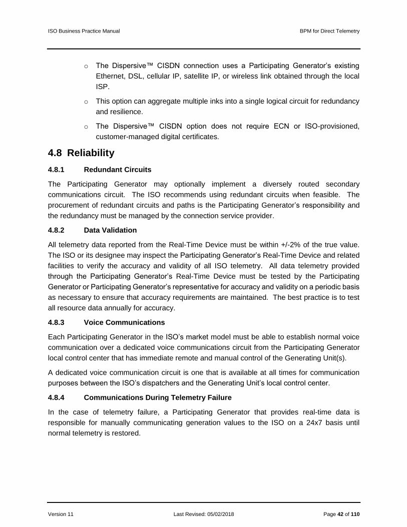
ISO Business Practice Manual BPM for Direct Telemetry
Version 11 Last Revised: 05/02/2018 Page 42 of 110
o The Dispersive™ CISDN connection uses a Participating Generator’s existing
Ethernet, DSL, cellular IP, satellite IP, or wireless link obtained through the local
ISP.
o This option can aggregate multiple inks into a single logical circuit for redundancy
and resilience.
o The Dispersive™ CISDN option does not require ECN or ISO-provisioned,
customer-managed digital certificates.
4.8 Reliability
4.8.1 Redundant Circuits
The Participating Generator may optionally implement a diversely routed secondary
communications circuit. The ISO recommends using redundant circuits when feasible. The
procurement of redundant circuits and paths is the Participating Generator’s responsibility and
the redundancy must be managed by the connection service provider.
4.8.2 Data Validation
All telemetry data reported from the Real-Time Device must be within +/-2% of the true value.
The ISO or its designee may inspect the Participating Generator’s Real-Time Device and related
facilities to verify the accuracy and validity of all ISO telemetry. All data telemetry provided
through the Participating Generator’s Real-Time Device must be tested by the Participating
Generator or Participating Generator’s representative for accuracy and validity on a periodic basis
as necessary to ensure that accuracy requirements are maintained. The best practice is to test
all resource data annually for accuracy.
4.8.3 Voice Communications
Each Participating Generator in the ISO’s market model must be able to establish normal voice
communication over a dedicated voice communications circuit from the Participating Generator
local control center that has immediate remote and manual control of the Generating Unit(s).
A dedicated voice communication circuit is one that is available at all times for communication
purposes between the ISO’s dispatchers and the Generating Unit’s local control center.
4.8.4 Communications During Telemetry Failure
In the case of telemetry failure, a Participating Generator that provides real-time data is
responsible for manually communicating generation values to the ISO on a 24x7 basis until
normal telemetry is restored.

ISO Business Practice Manual BPM for Direct Telemetry
Version 11 Last Revised: 05/02/2018 Page 43 of 110
5. Operational Telemetry Requirements
5.1 Unit Telemetry Visibility
Each resource participating in the ISO’s Ancillary Services markets or any Eligible Intermittent
Resource or any resource providing Energy with a capacity of 10MW or greater that is not exempt
pursuant to the ISO Tariff must provide telemetry data according to the point matrix specified in
Section 7 of this document and pursuant to ISO Tariff Section 7.6.1(d).
5.2 Performance Monitoring
5.2.1 Direct Telemetry Timing Requirements
Exhibit 5-1 shows the performance and timing requirements for a Generating Unit connected to
the ISO EMS.
• A Participating Generator must be able to accept and begin processing direct digital
control (DDC) signals (Set Points) within the ISO time standard (two-second maximum
from ISO’s EMS to output of the Real-Time Device). The two-second maximum
includes any Generator or third-party communication equipment located between the
ISO and the Participating Generator.
• A Participating Generator must be able to send data to the ISO within the ISO time
standard (two seconds from the input of the Real-Time Device to the ISO EMS).
• The plant controller must receive the signal from the Real-Time Device within the ISO
time standard (an additional two seconds from output of the Real-Time Device to plant
controller).
• The time standards also apply in the return direction, resulting in a total maximum of
eight seconds, round trip, for the signal to travel from the ISO EMS to the plant
controller and back.
• The timing requirements from the ISO EMS to the plant control system (for example,
DCS, RTU) through the use of non-ISO communication equipment must meet the ISO
two-second time standard in one direction.
• The timing requirements from the plant control system back to the ISO EMS through
the use of non-ISO communication equipment must meet the ISO two-second time
standard in the return direction.
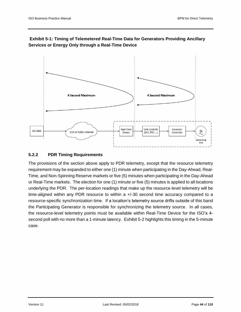
ISO Business Practice Manual BPM for Direct Telemetry
Version 11 Last Revised: 05/02/2018 Page 44 of 110
Exhibit 5-1: Timing of Telemetered Real-Time Data for Generators Providing Ancillary
Services or Energy Only through a Real-Time Device
5.2.2 PDR Timing Requirements
The provisions of the section above apply to PDR telemetry, except that the resource telemetry
requirement may be expanded to either one (1) minute when participating in the Day-Ahead, Real-
Time, and Non-Spinning Reserve markets or five (5) minutes when participating in the Day-Ahead
or Real-Time markets. The election for one (1) minute or five (5) minutes is applied to all locations
underlying the PDR. The per-location readings that make up the resource-level telemetry will be
time-aligned within any PDR resource to within a +/-30 second time accuracy compared to a
resource-specific synchronization time. If a location’s telemetry source drifts outside of this band
the Participating Generator is responsible for synchronizing the telemetry source. In all cases,
the resource-level telemetry points must be available within Real-Time Device for the ISO’s 4-
second poll with no more than a 1-minute latency. Exhibit 5-2 highlights this timing in the 5-minute
case.

ISO Business Practice Manual BPM for Direct Telemetry
Version 11 Last Revised: 05/02/2018 Page 45 of 110
Exhibit 5-2: PDR Timing, 5- Minute Case
The timing referenced this section also applies to PDR participating in the Spinning Reserve
Market.
Real-Time Devices providing telemetry for PDRs must provide valid data points only during the
time that the PDR is in a dispatchable state, including one hour leading up to and one hour after
that state. Dispatchable is defined as any time the resource has the potential for energy dispatch,
specifically during day-ahead award hours and real-time energy bids.
5.2.3 PDR Reading Requirements
The provisions in this document shall apply to PDR telemetry, except that all references to “real-
time updated value and not averaged over time” should be taken as “real-time updated value or
average reading over the PDR timing interval” for PDRs.
5.3 ISO Real-Time Communication Technical Design Options
With the recharacterization of a RIG as any Real-Time Device that meets the security and
operational objectives for direct telemetry, the ISO now supports both branded (turn-key) and
non-branded (build-your-own) technical designs. Hybrid solutions are also possible. Contact an
ISO Energy Data Acquisition Specialist for consultation using the contact information in the
References section of this BPM.
The ISO is continually looking for options that will allow Participating Generators to connect to the
ISO’s EMS in a cost-effective and secure manner. A Real-Time Device can be software running
on a Plant Control System or a combination of software optionally hardware on a separate device.
Its function as an interface to the ISO’s EMS can be either logically or physically segmented at
the Participating Generator’s site. This section describes multiple secure options that will allow
the Participating Generator’s control system to connect to the ISO’s EMS by means of a Real-
Time Device.

ISO Business Practice Manual BPM for Direct Telemetry
Version 11 Last Revised: 05/02/2018 Page 46 of 110
The ISO’s EMS controls and monitors resource sites from two physical locations with two
connections in simultaneous operation. This exchange of data is performed using Real-Time
Devices either over the ECN or using a Participating Generator’s existing broadband link.
5.3.1 Functional Components of Real-Time Communication Options
The functional components of real-time communication options, without regard to specific
implementation, are as follows.
• Plant Systems: Each plant providing Ancillary Services or Energy has a control system
that obtains telemetry from Generating Units. Various measured values must be available
from the Plant Control System as described in this BPM. The Plant Control System
constitutes the source of the telemetry necessary to comply with the ISO’s standards,
pursuant to ISO Tariff Section 7.6.1(d).
• Plant Interface Protocol: The interface between the Real-Time Device and the plant
control system can be any protocol convenient to the control system, according to the
relationship between the supplier and the Participating Generator.
• SSL/TLS Encryption Layer: With SSL/TLS, the ISO’s EMS real-time IP DNP3 poll
converts to TCP in-the-clear or serial DNP3 protocol at the resource control system. The
SSL/TLS capability may reside on the Plant Control System or on separate hardware.
• Dispersive™ CISDN: With this option, an alternative to the SSL/TLS, encryption layer,
the real-time DNP3-over-TCP/IP poll from the ISO’s EMS is encoded to traverse a resilient
software-define network. There is no requirement to manage digital certificates at the
plant. There is no requirement for ECN. Dispersive™ CISDN can reside on hardware
separate from the Plant Control System or as software on a Real-Time Device. For
resiliency, Dispersive™ CISDN supports multiple broadband links (Ethernet, DSL, cellular
IP, satellite IP, or wireless) and aggregation of those links.
• Exemption from Simultaneous Connection: The ISO may grant an exemption from the
requirement to establish two simultaneous connections for an intermittent resource with a
capacity less than 10MW. For resources with a capacity of 10MW or greater, both the
SSL/TLS and Dispersive™ CISDN options must meet the ISO standard for simultaneous
connections.
• ECN Connection: The Energy Communications Network (ECN) is a semi-private AT&T
MPLS communications network option for telemetry from the Real-Time Device to the
ISO’s EMS. AT&T provisions access to the ECN. The ECN natively has no encryption.
ECN connectivity is not required for the Dispersive™ CISDN option. AT&T can provision
ECN connectivity either as a T1 circuit with a customer-provisioned router or as an ANIRA
IPsec VPN tunnel to the ECN. The ANIRA gateway has Ethernet and cellular IP capability.

ISO Business Practice Manual BPM for Direct Telemetry
Version 11 Last Revised: 05/02/2018 Page 47 of 110
• Internet Connection: The connection option for the public Internet is for real-time data
through an ISP for the purpose of telemetry in the same manner as the ECN. The ANIRA
and Dispersive™ CISDN options support this method.
• Securing DNP3 over TCP/IP: The DNP3 protocol communicated over the TCP/IP
transport must be secured. The ISO’s EMS does not use the DNP3 SA (Secure
Authentication) extension but achieves the same, plus encryption, using one of the
following two methods:
o SSL/TLS with a customer-managed and periodically expiring digital certificate
provisioned by the ISO
o Dispersive™ CISDN managed security service
• ISO EMS: All telemetry arrives at the ISO’s EMS encrypted over TCP/IP via either the
ECN or an ISP network.
5.3.2 Transport Options
The ISO supports three transport options for direct telemetry:
1. ECN with T1 leased circuit.
2. Public Internet with ANIRA IPsec VPN backhaul to ECN.
3. Public Internet with Dispersive™ CISDN.
Option one requires the Participating Generator to lease a T1 circuit from AT&T to connect to the
ECN. This option does not use the public Internet. The Participating Generator must manage an
ISO-issued digital certificate to secure the communication link.
Option two requires the Participating Generator to provide a broadband circuit and to contract
with AT&T to install an ANIRA IPsec VPN gateway to connect to the ECN. The Participating
Generator does not need to lease a T1 circuit. The Participating Generator must manage an ISO-
issued digital certificate to secure the communication link.
Option three requires the Participating Generator to provide a broadband circuit and to contract
with Dispersive Technologies to install CISDN. The Participating Generator does not need to
lease a T1 circuit and does not need to manage an ISO-issued digital certificate to secure the
communication link.
5.3.3 Transport Conceptual Diagrams
The following diagrams conceptually depict each of the three transport options described above.
These diagrams do not depict the requirement for a Real-Time Device to receive two polls
simultaneously from each ISO EMS.

ISO Business Practice Manual BPM for Direct Telemetry
Version 11 Last Revised: 05/02/2018 Page 48 of 110
5.3.3.1 ECN with T1 leased circuit.
In Exhibit 5-3, Customer Edge refers to a router with a T1 interface that a Participating Generator
must purchase to connect to the ECN through the AT&T Provider Edge router. The Participating
Generator may optionally contract with AT&T for management of the Customer Edge router. The
key symbol labeled with SSL/TLS shows use of an ISO-issued digital certificate that the
Participating Generator must manage on the Real-Time Device.
Exhibit 5-3: Transport Option – ECN with T1 Leased Circuit
5.3.3.2 Public Internet with ANIRA IPsec VPN backhaul to ECN.
Exhibit 5-4 depicts the IPsec tunnel between the Participating Generator’s ANIRA gateway and
the ANIRA gateway (or concentrator) on the ECN edge. The Participating Generator provides a
broadband connection that serves as the site’s gateway for the IPsec tunnel over the public
Internet between the generator site and the ECN. The key symbol labeled with SSL/TLS shows
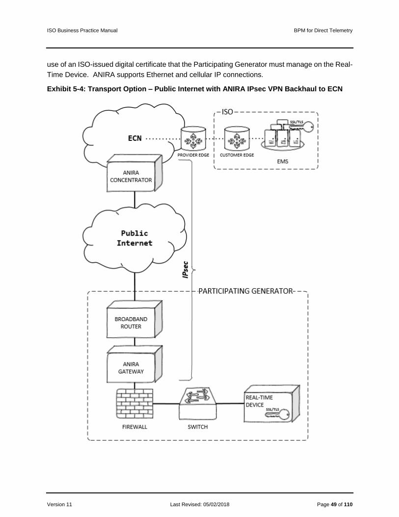
ISO Business Practice Manual BPM for Direct Telemetry
Version 11 Last Revised: 05/02/2018 Page 49 of 110
use of an ISO-issued digital certificate that the Participating Generator must manage on the Real-
Time Device. ANIRA supports Ethernet and cellular IP connections.
Exhibit 5-4: Transport Option – Public Internet with ANIRA IPsec VPN Backhaul to ECN
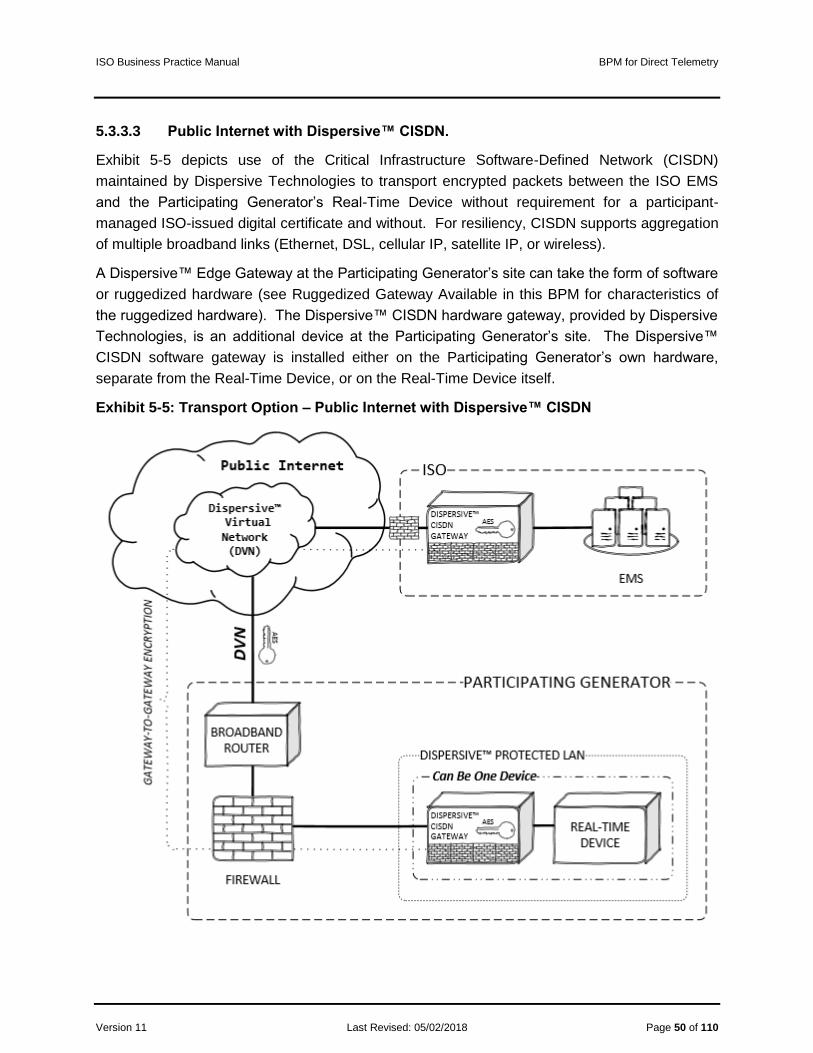
ISO Business Practice Manual BPM for Direct Telemetry
Version 11 Last Revised: 05/02/2018 Page 50 of 110
5.3.3.3 Public Internet with Dispersive™ CISDN.
Exhibit 5-5 depicts use of the Critical Infrastructure Software-Defined Network (CISDN)
maintained by Dispersive Technologies to transport encrypted packets between the ISO EMS
and the Participating Generator’s Real-Time Device without requirement for a participant-
managed ISO-issued digital certificate and without. For resiliency, CISDN supports aggregation
of multiple broadband links (Ethernet, DSL, cellular IP, satellite IP, or wireless).
A Dispersive™ Edge Gateway at the Participating Generator’s site can take the form of software
or ruggedized hardware (see Ruggedized Gateway Available in this BPM for characteristics of
the ruggedized hardware). The Dispersive™ CISDN hardware gateway, provided by Dispersive
Technologies, is an additional device at the Participating Generator’s site. The Dispersive™
CISDN software gateway is installed either on the Participating Generator’s own hardware,
separate from the Real-Time Device, or on the Real-Time Device itself.
Exhibit 5-5: Transport Option – Public Internet with Dispersive™ CISDN

ISO Business Practice Manual BPM for Direct Telemetry
Version 11 Last Revised: 05/02/2018 Page 51 of 110
The Dispersive™ CISDN option uses an advanced Cloud controller to provide immunity to data
interception through use of deflects or waypoints to splinter encrypted DNP3 protocol messages
at the site and reliably deliver and reassemble those messages at the ISO using optimized
checksumming algorithms. Access to the Dispersive network is strictly controlled based on a
zero-trust model.
The CISDN service option available to Participating Generator’s is called Fully Managed SaaS
with Field Gateway IPP-1000. For more information on CISDN, see Establishing Dispersive™
CISDN Connectivity with the ISO under References.
• With the CISDN transport option, there is no requirement for the Participating Generator
to lease a T1 circuit from AT&T.
• This diagram uses a “cloud within a cloud” concept to illustrate use of the Dispersive™
Virtual Network (DVN) to splinter packet pieces across a managed network of waypoints
between the CISDN gateways before reassembling the data at the receiving end.
• Transport is optimized using reliable UDP algorithms between the CISDN gateways with
no effect on the DNP3 over TCP required by the ISO’s EMS and the Participating
Generator’s Real-Time Device.
• The key symbol with AES refers to encryption of packet data between the CISDN
gateways using the Advanced Encryption Standard.
• The Dispersive™ CISDN gateway can be physical hardware that protects the Real-Time
Device or can be software installed on the Real-Time Device.
• The Dispersive™ Protected LAN shown in the diagram could be a zone on the site’s edge
firewall; the general concept is that CISDN occupies a “LAN within a LAN” at the
Participating Generator’s site, with implementation details left to the Participating
Generator to determine.
• The firewall symbol embedded on the CISDN gateway illustrates use of an integrated
firewall to block non-CISDN traffic and enforce allowed communication only between the
ISO and trusted CISDN sites. Allowed CISDN connections are enforced at a peer-to-peer
level in the DVN using only defined protocols and ports.
Exhibit 5-6 depicts the Dispersive™ CISDN option in full context with the plant’s physical
boundary and CISDN Cloud components. The Dispersive™ Edge Gateway and the Real-Time
Device as physically separate devices; these functions, however, can exist on a single physical
device. The Real-Time Device at the plant must communicate DNP3 protocol over TCP port
20000. The ISO may grant an exemption from the requirement to establish two simultaneous
connections for an intermittent resource with a capacity less than 10MW. For resources with a
capacity of 10MW or greater, the Dispersive™ CISDN options must meet the ISO standard for
simultaneous connections.

ISO Business Practice Manual BPM for Direct Telemetry
Version 11 Last Revised: 05/02/2018 Page 52 of 110
Exhibit 5-6: Dispersive™ CISDN Hardware Option
5.3.4 Direct Telemetry Hardware Options
The purpose of this section is to illustrate hardware options for direct telemetry. Participating
Generators have the option to build their own Real-Time Devices to interface to plant devices.
Unless using the ANIRA transport option, Participating Generators also have the option to install
or build their own security devices, as long as those devices meet ISO security objectives. There
are three security options: SSL/TLS, IPsec plus SSL/TLS, and Dispersive™ CISDN.
5.3.4.1 Plant Control System Hardware Option
In this option, the Plant Control System functions as the Real-Time Device. The software can
reside on the Plant Control System. The device performs either an SSL/TLS connection or a
CISDN connection for DNP3 data over TCP.
The ISO’s EMS communications with the Plant Control System using the DNP3 protocol. For this
option, the Plant Control System must have an outstation DNP3 protocol driver. Real-time data
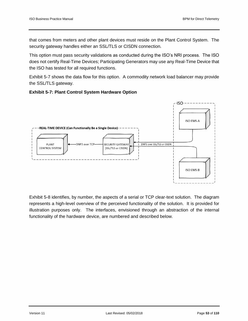
ISO Business Practice Manual BPM for Direct Telemetry
Version 11 Last Revised: 05/02/2018 Page 53 of 110
that comes from meters and other plant devices must reside on the Plant Control System. The
security gateway handles either an SSL/TLS or CISDN connection.
This option must pass security validations as conducted during the ISO’s NRI process. The ISO
does not certify Real-Time Devices; Participating Generators may use any Real-Time Device that
the ISO has tested for all required functions.
Exhibit 5-7 shows the data flow for this option. A commodity network load balancer may provide
the SSL/TLS gateway.
Exhibit 5-7: Plant Control System Hardware Option
Exhibit 5-8 identifies, by number, the aspects of a serial or TCP clear-text solution. The diagram
represents a high-level overview of the perceived functionality of the solution. It is provided for
illustration purposes only. The interfaces, envisioned through an abstraction of the internal
functionality of the hardware device, are numbered and described below.

ISO Business Practice Manual BPM for Direct Telemetry
Version 11 Last Revised: 05/02/2018 Page 54 of 110
Exhibit 5-8: Plant Control System Hardware Option Functional Diagram
1. Plant Control System: Must perform all Real-Time Device functionality described in
this document.
2. DNP3 Output Interface Protocol Layer: The Plant Control System must
communicate with the DNP3 subordinate protocol and support the objects and
variations described in this document.
3. Encryption Layer: This layer will be an implementation of SSL/TLS using ISO-issued
digital certificates or an implementation of Dispersive™ CISDN.
4. TCP/IP Output Interface Layer: The serial to IP device acts as the TCP
server/connection. Once the serial to IP device has requested and established the
TCP connection, the encrypted DNP3 compatible data stream passes through a
TCP/IP connection over a TCP/IP network.
5. DNP3 over TCP/IP over SSL/TLS or DNP3 over CISDN: Secure DNP3 data over
TCP/IP is achieved when the encrypted DNP3 compatible data stream is transported
onto the TCP/IP network. Encryption is provided by SSL/TLS or Dispersive™ CISDN.
6. ISO Multi-Porting Capability: The security device must have one IP address with
the ability to communicate with two simultaneous TCP/IP connections sourced from
the ISO’s EMS. For resources with a capacity of less than 10 MW and for intermittent
resources, the ISO may grant an exemption from the requirement for multiple
simultaneous connections.
5.3.4.2 Real-Time-Device Hardware Option
This options consists a Real-Time Device that functions as a protocol interface to the Plant Control
System and an SSL/TLS interface to the ISO’s EMS. The ISO’s EMS communications with the
Real-Time Device using the DNP3 protocol. This option may be used when a Participating
Generator’s control system cannot communicate DNP3 protocol. The Real-Time Device provides
SSL/TLS security. The ISO does not certify Real-Time Devices; Participating Generators may

ISO Business Practice Manual BPM for Direct Telemetry
Version 11 Last Revised: 05/02/2018 Page 55 of 110
use any Real-Time Device that the ISO has tested for all required functions. Exhibit 5-9 shows
the data flow for this option.
Exhibit 5-9: Real-Time Device Hardware Option
Exhibit 5-10 identifies, by number, the critical aspects of the ISO Real-Time Device. The diagram
represents a high-level overview of the perceived functionality of an acceptable Real-Time Device
in a single hardware device. This diagram is an illustration only. The interfaces, envisioned
through an abstraction of the internal functionality of the hardware device, are numbered and
described below.
Exhibit 5-10: Real-Time Device Hardware Option Functional Diagram
1. Plant Interface Protocol: The input to the Real-Time Device is a data stream
compatible with the plant systems. This may also be individual hardwired inputs.

ISO Business Practice Manual BPM for Direct Telemetry
Version 11 Last Revised: 05/02/2018 Page 56 of 110
2. Internal Plant Interface Protocol Layer: The input data stream is received internally
by an interface layer compatible with the plant systems.
3. Real-Time Device Point Database / DNP3 Database Profile Specifics: The input
data is processed internally in the Real-Time Device as data points in a DNP3-
compatible database structure. Since the real-time data must be compliant with DNP3
Level 1 protocol, and can contain a database large enough to require more than a
single datalink frame for a Class 1 data response, the Real-Time Device must support
both static and event-type data points. The Real-Time Device is required to support
polling by class.
4. DNP3 Output Interface Protocol Layer: As the DNP3 server, the Real-Time Device
will parse all client requests and supply the appropriate data designated in the Real-
Time Device Point Database. This is typical of a DNP3 driver storing data into the
real-Time database.
5. SSL/TLS Encryption Layer: In transferring the data from the Real-Time Device to a
DNP3-compatible destination, elements are encrypted by a SSL/TLS encryption
interface layer using ISO-issued basic-assurance digital certificates implemented
either in the ECN or the public Internet.
6. TCP/IP Output Interface Layer: The Real-Time Device is to act as the TCP
server/connection. Once the client device has requested and established the TCP
connection, the encrypted DNP3-compatible data stream passes through an interface
layer over a TCP/IP network.
7. DNP3 over TCP/IP over SSL/TLS: The DNP3 data stream is secured over TCP/IP
using SSL/TLS encryption and transported over a TCP/IP network.
8. ISO Multi-Porting Capability: The Real-Time Device must have one IP address that
has the ability to communicate with two simultaneously connections sourced from the
ISO’s EMS.
5.4 ISO EMS Interrogations
The ISO’s EMS DNP3 front-end processors interrogate each Real-Time Device with DNP3 Object
60, Variations 2 for event data polling (class 1 data). Responses shall be the event objects and
variations listed below. If there is no points designated as class 1 then the ISO will be instructed
by the DNP3 Real-Time Device that protocol driver of data in another class, this is handled and
inherent to the DNP3 driver.
ISO Business Practice Manual BPM for Direct Telemetry
Version 11 Last Revised: 05/02/2018 Page 57 of 110
The ISO’s EMS DNP3 front-end processors interrogate each Real-Time Device with DNP3 Object
01 Variation 00 “digital static updates” and Object 30 Variation 00 for “analog static updates.” The
Real-Time Device response must be among the Static Objects and Variations.
5.5 DNP3 Object and Variation Types for Real-Time Device
Responses
Objects and Variations supported by the Real-Time Device must include, but are not limited to:
• Static: Object 1 Variation 2 (Digital)
Object 30 Variation 2 (Analog)
• Event: Object 2 Variation 1 (Digital)
Object 32 Variation 2 (Analog)
• Time: Object 50 Variation 1 (Read and Write)
• Control: Object Type 41 (Analog Setpoint) Variation 2
Important
The ISO’s EMS DNP3 front-end processors will use DNP3 group and variations other than those
listed above. All Real-Time Device solutions must be DNP3 Level 1 certified.
Deadband: Analog events should be set to .5 Engineering Units. The deadband must be
configurable on a point-by-point basis. Exception for the analog deadband is analog points
associated with wind, solar, and PDR resources. These types of resources have a much smaller
deadband requirement and higher resolution. Consult ISO EDAS for proper deadband settings.
5.6 Quality Flag Propagation to DNP3
When a Participating Generator installs a Real-Time Device and it communicates to downstream
devices that are not directly connected to the Real-Time Device, the originating device(s) shall
propagate a data quality communication flag for each point to the Real-Time Device through each
non-originating device. A data port alarm point may not be required; however, this will be
determined by ISO Energy Data Acquisition Specialist. Other protocols with data quality flags
maybe used to propagate flags into DNP3 flags (OPC).
An originating device is one that gathers field data directly (for inputs) or issues controls directly
to the field (for outputs). A non-originating device is one that obtains input data or issues control
commands via a communications link from originating or non-originating devices. A reporting
device is a device that acts as a DNP3 outstation, sending DNP3 messages to an upstream
device.

ISO Business Practice Manual BPM for Direct Telemetry
Version 11 Last Revised: 05/02/2018 Page 58 of 110
Data from an originating device may arrive at the master via one or more data concentrator
devices. In this case, each device in the communications chain, other than the master, is a
reporting device. Exhibit 5-11 illustrates device identification. The terms “upstream” and
“downstream” that indicate relative device hierarchy are also shown in this diagram.
Exhibit 5-11: Upstream and Downstream Device Identification
Originating
Device
Non-
Originating/
Reporting
Device
Non-
Originating/
Reporting
Device
Real-time
Device
Communication LinksUpstream Downstream
A COMM_LOST indicator indicates that there is a communication failure in the path between the
device where the data originates and the reporting device on a point to point basis. This flag
indicates that the value reported for the object may be stale or in bad quality. If set, the data value
reported shall be the last value available from the originating device before communications were
lost.
An originating device never sets this flag. A non-originating or master device sets this flag if it
loses communication with the adjacent downstream device; otherwise it propagates the state of
COMM_LOST flag as received from the downstream device. Once set, this flag may only be
cleared when data for this point is received from the adjacent downstream device and the
COMM_LOST flag received with that data is cleared.
5.7 Maximum MW Real-Time Device Limitation
The ISO’s grid and market operations depend on data from a Real-Time Device to reliably run
real-time operations, the Full Network Model, and the State Estimator. To minimize potential
impact to the ISO’s grid and market operations, the ISO sets a maximum MW limitation. The
limitation is set to protect the ISO’s markets and grid, should a Real-Time Device failure occur.
The maximum generation that can be put on a single Real-Time Device cannot exceed 1200 MW
from a physical location. This includes the ECN circuit and router. The ISO reserves the right to
review all proposed telemetry systems for compliance with this and other Real-Time Device
limitations.
For Eligible Intermittent Resources and real-time Aggregators, the maximum combined
generation for a single device, including the communication circuit and router, is 1200 MW.

ISO Business Practice Manual BPM for Direct Telemetry
Version 11 Last Revised: 05/02/2018 Page 59 of 110
5.8 Real-Time Device Location Requirements
The purpose of a real-time location requirement is to limit the impact of possible real-time failures
to a smaller geographical area. Location limits are defined by the standard 23 Sub-LAPs within
the ISO Balancing Authority Area. The location limitation provides that only resources within a
Sub-LAP can be aggregated within a Real-Time Device. The Real-Time Device shall reside within
the Sub-LAP for the resources it is aggregating.
The ISO can make an exception to the location limits for aggregating resources within a Real-
Time Device if a resource is located in an adjacent Sub-LAP that does not have a Real-Time
Device.
A Real-Time Device Aggregator can combine multiple physical resource locations within a Sub-
LAP. The MW limitation and limitation of aggregation location to Sub-LAPs is due to the
unpredictable nature of these resource types (that is, solar and wind). Only a ISO Energy Data
Acquisition Specialist may authorize an exception to location limits. The list of the Sub-LAPs is
set forth in Section 19.
These limitations do not apply if a Real-Time Device Aggregator desires to transmit real-time data
to the ISO for information only. The Real-Time Device location limitations do not apply to Real-
Time Devices used in the transmission of real-time data by Demand Response Providers (DRP)
to the ISO for Proxy Demand Resources.
5.9 Real-Time Device Market Resource Limitation
The purpose of a resource limit is to mitigate the impact of a Real-Time Device failure on the
ISO’s market Model State Estimator. If the ISO loses communication with many resources at
once, it may impact the ISO’s modeling calculations. To mitigate this risk, the ISO has set the
resource limit for a single Real-Time Device to 25 Resource IDs, subject to defined MW limits.
5.10 Cost Responsibility
Each Participating Generator will be responsible for all costs incurred for Real-Time Device
procurement and installation for the purpose of meeting its obligations under this ISO BPM,
notwithstanding other ISO policies, procedures, and contracts that may affect the distribution of
costs to participating parties.

ISO Business Practice Manual BPM for Direct Telemetry
Version 11 Last Revised: 05/02/2018 Page 60 of 110
6. Telemetry Data Points List
The following values are the minimum requirements for real-time visibility of each resource. The
ISO’s Operations & Engineering groups have approved these requirements. They are the
minimum standards that will allow the ISO to manage effectively the reliability of the grid. At any
time, the ISO may require additional points to be added to meet real-time requirements. The
following points must be provided for each resource in the specified category. The Participating
Generator must obtain the required point list from an ISO Energy Data Acquisition Specialist.
6.1 Point Matrix
The following pages represent the minimum point requirement matrix for each type of Real-Time
Device configuration that the ISO requires for real-time control or monitoring. The matrix specifies
the telemetry points required for the following categories of resources:
AGC: Resources certified to provide Regulation in the ISO Markets.
Spinning Reserve: Resources certified to provide Spinning Reserve in the ISO Markets.
Non-Spinning Reserve: Resources certified to provide Non-Spinning Reserve in the ISO
Markets.
QF Conversion: Resources that are Qualifying Facilities not exempt from ISO Tariff
telemetry requirements pursuant to pre-existing agreements. Note that MW, MVAR, and
voltage values are measured based on the Point of Demarcation for a Net Scheduled
subject to a NS PGA.
Energy Only: Resources that provide Energy only.
PDR: Proxy Demand Resources.
Solar: Solar resources.
Wind: Wind resources.
If a resource falls within more than one category, the Participating Generator or Real-Time
Aggregator must provide the telemetry points specified for each applicable category.
Real-Time Point Definitions in this document has the detailed definitions in Table 6-1.

ISO Business Practice Manual BPM for Direct Telemetry
Version 11 Last Revised: 05/02/2018 Page 61 of 110
Table 6-1: Required Real-Time Points by Technology or Service
Notes to Analog and Digital Notes in the next section.
Analogs AGC Spinning Reserve
Non-Spinning Reserve
QF Conversion
Energy Only PDR Solar
Wind
Solar/Wind less than 10MW Battery
Unit Gross MW
X X X X Note 9 X X Note
10 X X
Unit Net MW
X Note 1
X Note 1 X Note 1 X Note 1 & 9 X Note 1 XNote 1
Unit Point of delivery MW
X X X X X X X X X
Unit Auxiliary MW
X Note 2
X Note 2 X Note 2 X Note 2 & 9 X Note 2 XNote 1
Pseudo Gen MW
X
Bias Load MW
X
Unit Generator Terminal Voltage
X X X X X X X XNote 12 X
Unit Gross MVAR
X X X XNote 9 X X X
Unit Net MVAR
X Note 3
X Note 3 X Note 3 X Note 3 & 9 X Note 3 XNote 3
Point of delivery MVAR
X X X X X X X X X
Auxiliary MVAR
X Note 4
X Note 4 X Note 4 X Note 4 & 9 X Note 4 XNote 3
Capacitor Bank VAR
X X

ISO Business Practice Manual BPM for Direct Telemetry
Version 11 Last Revised: 05/02/2018 Page 62 of 110
Analogs AGC Spinning Reserve
Non-Spinning Reserve
QF Conversion
Energy Only PDR Solar
Wind
Solar/Wind less than 10MW Battery
High\Line Side Bank MW
X Note 5
X Note 5 X Note 5 X Note 5 X Note 5 X X
High\Line Side Bank MVAR
X Note 5
X Note 5 X Note 5 X Note 5 X Note 5 X X
High\Line Side Bank Voltage
X Note 5
X Note 5 X Note 5 X Note 5 X Note 5 X X
Aggregated Gross MW
X Note 6
X Note 6 X Note 6 X Note 9 X Note 6 X Note
10
Aggregated Net MW
X Note 6
X Note 6 X Note 6 X Note 9 X Note 6
Aggregated Point of delivery MW
X Note 6
X Note 6 X Note 6 X Note 6 X Note 6
Aggregated Gross MVAR
X Note 6
X Note 6 X Note 6 X Note 6 X Note 6
Resource ID Setpoint Feedback
X
RIG Heart Beat
X X X X X X X X X X
Aggregate\Unit Operating High Limit
X

ISO Business Practice Manual BPM for Direct Telemetry
Version 11 Last Revised: 05/02/2018 Page 63 of 110
Analogs AGC Spinning Reserve
Non-Spinning Reserve
QF Conversion
Energy Only PDR Solar
Wind
Solar/Wind less than 10MW Battery
Aggregate\Unit Operating Low Limit
X
Wind Speed (Meter / Second)
X X X
Wind Direction (Degrees - Zero North 90CW)
X X X
Air Temperature (Degrees Celsius)
X X X
Barometric Pressure (HPA)
X X X
Back Panel Temperature (Degree C)
X Note
11 X Note 11
Plane Of Array Irradiance Watts\Meter Sq.
X Note
11 X Note 11

ISO Business Practice Manual BPM for Direct Telemetry
Version 11 Last Revised: 05/02/2018 Page 64 of 110
Analogs AGC Spinning Reserve
Non-Spinning Reserve
QF Conversion
Energy Only PDR Solar
Wind
Solar/Wind less than 10MW Battery
Global Horizontal Irradiance Watts\Meter Sq.
X Note
11 X Note 11
Direct Irradiance Watts\Meter Sq.
X Note
11 X Note 11
Diffused Plane Of Array Irradiance Watts\Meter Sq.
X Note
11 X Note 11
Diffused Global Horizontal Irradiance Watts\Meter Sq.
X Note
11 X Note 11
Reference Cell (MW @ .001 resolution)
X Note
11 X Note 11
Instantaneous State of charge
X
Maximum Continuous Energy limit
X

ISO Business Practice Manual BPM for Direct Telemetry
Version 11 Last Revised: 05/02/2018 Page 65 of 110
Digitals AGC Spinning Reserve
Non-Spinning Reserve
QF Conversion
Energy Only PDR Solar
Wind
Solar/Wind Less Than 10MW Battery
Unit\Resource Connect
X X X X X X X X X
PDR Resource Connect
X
Power System Stabilizer
X Note 7
X Note 7 X Note 7 X Note 7 X Note 7
Automatic Voltage Regulator
X Note 7
X Note 7 X Note 7 X Note 7 X Note 7 X Note
7
Capacitor Bank Breakers
X X
Unit Low Side Breaker
X X X X X X X XNote 13
Related Unit Breakers
X X X X X X X X
Related Unit MOD's Disconnects
X X X X X X X
Switchyard Line Breakers (if Generator Owned)
X X X X X X X
Switchyard Line MOD (if Generator Owned)
X X X X X X X
Aggregated\Unit Connected
X Note 6
X Note 6 X Note 6 X Note 6 X Note 6 X Note
6
Aggregated\Unit Authority Switch
X Note 8
Aggregated\Unit Control Switch
X Note 8

ISO Business Practice Manual BPM for Direct Telemetry
Version 11 Last Revised: 05/02/2018 Page 66 of 110
Digitals AGC Spinning Reserve
Non-Spinning Reserve
QF Conversion
Energy Only PDR Solar
Wind
Solar/Wind Less Than 10MW Battery
Aggregated\Unit Automatic Generation Control
X Note 8

ISO Business Practice Manual BPM for Direct Telemetry
Version 11 Last Revised: 05/02/2018 Page 67 of 110
6.2 Analog and Digital Notes
1. If Aux MW are over 1 MW then Net MW are required.
2. Required If Aux MW are over 1 MW.
3. If Aux MW are over 1 MW then Net MVR are required.
4. Required if Aux MW are over 1 MW.
5. Transformer High Side or Line values required depending on meter location.
6. Provide Unit Connected and Gross MW for each unit and aggregated values if
Resource ID is an aggregate. Individual POD not required if the Resource ID is an
aggregate.
7. PSS / AVR indication is needed if plant is required to install these devices.
8. Required point for each Resource ID.
9. Required if the QF is not subject to a QF Participating Generator Agreement.
10. Resolution @ .001 Gross MW = POD.
11. See the Solar Meteorological Data Tables in Section 13.5 and definitions of data
points in Section 17.4. Note that some data points are not required from solar
thermal facilities.
12. Voltage from ISO meter at metering point
13. This does not have to be an actual circuit breaker but an indication from some device
within the system showing when the resource is physically connected or
disconnected to the grid. One point only per resource

ISO Business Practice Manual BPM for Direct Telemetry
Version 11 Last Revised: 05/02/2018 Page 68 of 110
7. Availability and Maintenance
7.1 ISO Reliability Requirements
The Participating Generator shall be responsible for maintaining the availability of the Real-Time
Device, all Real-Time Device interface systems, and Real-Time Device communications access
to the communication network either to the ISP or ECN.
Risk of loss, theft, or damage of the Real-Time Device will be the responsibility of the Participating
Generator.
A Participating Generator will be solely responsible, at the Participating Generator’s cost, for
preparing and maintaining the site at which a Real-Time Device will be installed, and for
engineering, installation, operation, and maintenance of that Real-Time Device and all other
activities associated with the installation, operation, and maintenance of that Real-Time Device;
except that this provision does not supersede agreements addressing responsibility for costs of
engineering, design, installation, and testing set forth in any agreement for the installation of a
Real-Time Device. The ISO will provide support as described herein to ensure that the Real-
Time Device properly interfaces with the ISO’s EMS.
The local communications access circuit generally represents the highest risk to plant interface
availability. Proper engineering of circuit pathways with alternate paths and redundancy wherever
feasible is recommended. In all cases, the ISO recommends that the Participating Generator
consider implementing a backup circuit to maintain communications.
A Participating Generator of a Real-Time Device is responsible for:
• Meeting the ISO network security requirements of either using SSL/TLS or
Dispersive encryption methods
• Acting as the main point of contact for any data quality issue.
• Ensuring the accuracy of the data transmitted to the ISO.
• Resolving any data quality issues identified by the ISO.
• For a Real-Time Device Aggregator, see Section 15.
7.2 ISO-Controlled Grid Operation and Market Availability
Requirement
A Participating Generator is solely responsible for all costs and other consequences associated
with the unavailability of the Real-Time Device and the inability of the Real-Time Device to
communicate with the ISO’s EMS, including any financial consequences pursuant to the terms of
the ISO Tariff. Such failure may result in penalties for failure to perform in accordance with the
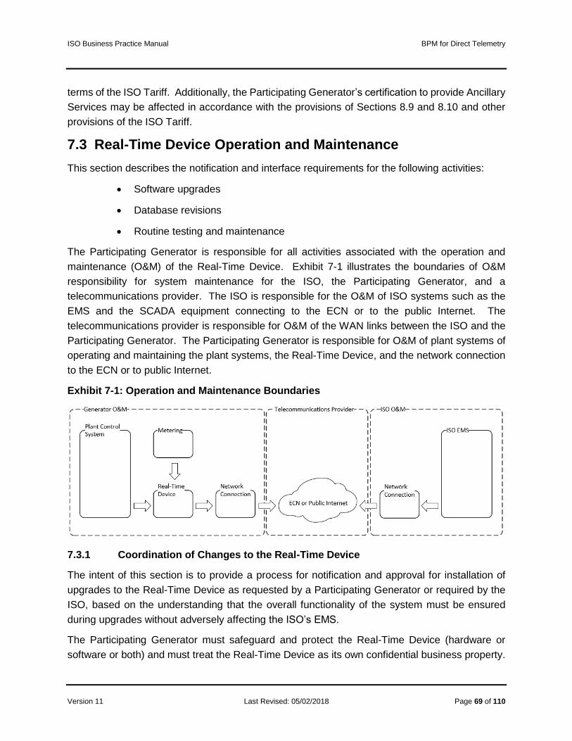
ISO Business Practice Manual BPM for Direct Telemetry
Version 11 Last Revised: 05/02/2018 Page 69 of 110
terms of the ISO Tariff. Additionally, the Participating Generator’s certification to provide Ancillary
Services may be affected in accordance with the provisions of Sections 8.9 and 8.10 and other
provisions of the ISO Tariff.
7.3 Real-Time Device Operation and Maintenance
This section describes the notification and interface requirements for the following activities:
• Software upgrades
• Database revisions
• Routine testing and maintenance
The Participating Generator is responsible for all activities associated with the operation and
maintenance (O&M) of the Real-Time Device. Exhibit 7-1 illustrates the boundaries of O&M
responsibility for system maintenance for the ISO, the Participating Generator, and a
telecommunications provider. The ISO is responsible for the O&M of ISO systems such as the
EMS and the SCADA equipment connecting to the ECN or to the public Internet. The
telecommunications provider is responsible for O&M of the WAN links between the ISO and the
Participating Generator. The Participating Generator is responsible for O&M of plant systems of
operating and maintaining the plant systems, the Real-Time Device, and the network connection
to the ECN or to public Internet.
Exhibit 7-1: Operation and Maintenance Boundaries
7.3.1 Coordination of Changes to the Real-Time Device
The intent of this section is to provide a process for notification and approval for installation of
upgrades to the Real-Time Device as requested by a Participating Generator or required by the
ISO, based on the understanding that the overall functionality of the system must be ensured
during upgrades without adversely affecting the ISO’s EMS.
The Participating Generator must safeguard and protect the Real-Time Device (hardware or
software or both) and must treat the Real-Time Device as its own confidential business property.

ISO Business Practice Manual BPM for Direct Telemetry
Version 11 Last Revised: 05/02/2018 Page 70 of 110
The Participating Generator must ensure that no person having access to the Real-Time Device
attempts to modify or reverse engineer the Real-Time Device software. The Participating
Generator must also take reasonable steps to ensure that all persons having access to the Real-
Time Device observe the Participating Generator’s obligations relating to the Real-Time Device.
The ISO maintains a database that contains, for each Real-Time Device, the data points required
from the Real-Time Point Definitions contained in this document. This Real-Time Device
database may also contain additional data as required for mapping to the ISO’s EMS. In order to
maintain operation of the EMS, the ISO requires prior notification and approval of all revisions to
this Real-Time Device database.
A Participating Generator may make modifications to its Real-Time Device to support its
operations, including the addition of data input/output points (which may or may not be made
available to the ISO) and the addition or replacement of hardware, as required to accomplish the
Participating Generator’s purposes, provided that:
• The Participating Generator coordinates such changes with the ISO and first obtains from
an ISO Energy Data Acquisition Specialist the relevant information from the latest revision
of the ISO database of Real-Time Devices.
• The Participating Generator remains solely responsible for all costs and other
consequences associated with any interruption, as a result of such changes or
modifications, in the ability of the Real-Time Device to communicate with the ISO’s EMS,
including financial consequences, according to the ISO Tariff.
• The Participating Generator notifies the ISO at least seven days prior to any revision.
• The Participating Generator submits a database revision for review by an ISO Energy
Data Acquisition Specialist and clearly states the proposed database changes, including
the new revision, the installation date, and a valid OMS outage number.
• Following ISO approval of the database revision request, the Participating Generator
adheres to the requirements contained in this document during the installation of the
changes.
• The Participating Generator notifies the ISO before installation of the changes and
participates with the ISO in joint testing prior to placing the Real-Time Device back in
service.
The ISO requires prior notification and approval of all vendor software upgrades to the Real-Time
Device in order to assure that the changes do not have an adverse impact on the ISO’s EMS.
The Participating Generator’s obligations are as follows:

ISO Business Practice Manual BPM for Direct Telemetry
Version 11 Last Revised: 05/02/2018 Page 71 of 110
• The Participating Generator must notify the ISO at least seven days prior to any
software upgrade installation.
• The Participating Generator must provide a valid OMS outage number that clearly
covers the software upgrade. (For more information outage coordination, see ISO
documentation on Outage Coordination under References.)
• Upon the ISO’s approval of the software upgrade installation request, and during
installation of the upgrade, the Participating Generator must adhere to all requirements
contained in this document and must follow all Outage Coordination process in
accordance with the ISO Tariff.
• The Participating Generator must notify an ISO Energy Data Acquisition Specialist
before installation of any software upgrade affecting a Real-Time Device.
7.3.2 Database Configuration and Management Affecting the ISO’s EMS
The intent of this section is to provide a process for changes to a Real-Time Device database in
the event of modifications, either by the ISO or by the Participating Generator, that affect the
functionality of the ISO’s EMS software or database.
• In the event that the ISO requires changes, the ISO will notify each affected
Participating Generator 120 days in advance of such changes and will provide a
detailed explanation of the changes to be made.
• In the event that the Participating Generator requires changes to the Real-Time Device
database that affect the ISO’s EMS software or database, the Participating Generator
must contact a ISO Energy Data Acquisition Specialist 120 days in advance of the
requested change.
o In this case, the Participating Generator is responsible for making any necessary
conforming changes to the Real-Time Device to maintain the interface with the
ISO’s EMS.
o The ISO will work with Participating Generators to stage the work so that no
Generating Unit will be adversely affected in its ability to provide Regulation due
to the unavailability of the human resources required to accomplish the changes.
• Any such modifications or changes must not compromise the Participating Generator’s
right or ability to restrict access to information associated with the Participating
Generator’s resources by any party.
7.3.3 Routine Testing and Maintenance of Real-Time Devices
The Participating Generator is solely responsible for the completeness and accuracy of all
information transmitted by a resource to the Real-Time Device. The ISO will not be responsible

ISO Business Practice Manual BPM for Direct Telemetry
Version 11 Last Revised: 05/02/2018 Page 72 of 110
for the quality of the data transmitted through the Real-Time Device; the ISO will only validate this
information for accuracy. The ISO and the Participating Generator must monitor the Participating
Generator’s data transmitted through the Real-Time Device and, upon observation of any
problems with that data, either party must provide the other party notice of the problem and both
must work together to correct the problem.
The Participating Generator is responsible for all routine testing and maintenance of the real-time
devices RIGs. The intent is to provide resource owners with the process to follow in order to
maximize RIG operation while periodic maintenance and/or testing is performed. Minimizing the
loss of real-time device RIG communication, and thereby minimizing the period when a resource
is unavailable for bidding in the Ancillary Services markets, is in the best interest of both the
resource owner and the CAISO. The resource owner must also avoid sending spurious or
inaccurate data through the RIG real-time device as a result of testing and maintenance activities
without first coordinating test plans and actions with the CAISO. Spurious and inaccurate data
sent through a real-time device RIG to the CAISO and which the CAISO is not expecting to receive
will impact the CAISO’s real time Balancing Authority Area load and reserve requirements
calculations and its markets.
• planned periodic maintenance and testing of the Real-Time Devices should be performed
during scheduled resource outages.
• The Participating Generator understands that loss of Real-Time Device communication
will result in the inability of the resource to participate in Ancillary Services markets.
• In the event that a resource has failed to communicate or provide telemetry for seven
calendar days (consecutive or nonconsecutive), the ISO will send a letter to the
Scheduling Coordinator. If compliance issue are not resolved within 30 days, the ISO will
send an additional letter to inform the Participating Generator and Scheduling Coordinator
that the resource’s ability to participate in Energy or Ancillary Services markets may be
removed.
• Outages must be requested through the resource’s Scheduling Coordinator. Planned
work on Real-Time Devices should take place only between the hours of 8:00 am and
4:00 pm Pacific time, Monday through Friday, excluding ISO holidays. (For more
information, see ISO documentation on Outage Coordination under References.)

ISO Business Practice Manual BPM for Direct Telemetry
Version 11 Last Revised: 05/02/2018 Page 73 of 110
8. Real-Time Device Implementation
8.1 Engineering and Deployment
The Participating Generator is responsible for all procurement, engineering services, and
maintenance with regard to the installation of the Real-Time Device. The ISO suggests that the
first step in the installation process be that the resource coordinates a “kick off” meeting.
8.2 Real-Time Device Database Development
The ISO’s Real-Time Device Engineer will provide technical assistance as required to the
Participating Generator during the Real-Time Device hardware selection process. ISO EDAS will
also provide assistance during the development of the Real-Time Device database.
8.3 Telecommunication Circuit Installation and Power
Requirements
The Participating Generator may obtain communication access circuit(s) from the ECN provider
or an ISP provider. The LEC is responsible to provide the circuit to the plant main point of entry
(MPOE) only. It is the Participating Generator’s responsibility to provide for, or contract services
for, the implementation of high voltage protection (HVP) for these circuits where required. It is
also the Participating Generator’s responsibility to provide on-site extension of the communication
network circuit(s) to the actual Real-Time Device cabinet location on-site.
All service power to communication equipment and the Real-Time Device must be powered by
an uninterruptable power supply (UPS) for the same amount of time the LEC is providing. This
is not limited to Real-Time Device router, fiber optic power on both ends of the cabling, and
Channel Service Unit/Data Service Unit (DSUCSU). Any communication equipment and device
providing communications to the Real-Time Device must install a UPS or equivalent. For Eligible
Intermittent Resources, see Power Reliability Requirements in this document.
8.4 Temporary Telemetry Exemptions
The ISO may grant a temporary telemetry exemption for a resource that is new to participation in
the ISO’s markets, but an exemption is not guaranteed. The exemption is used for a Participating
Generator that is unable to comply with applicable telemetry requirements prior to the transition
of its resource to commercial operations in the ISO’s markets.
Temporary telemetry exemptions are focused on particular data. A Participating Generator must
provide all required documentation in order to submit a request for a telemetry exemption.

ISO Business Practice Manual BPM for Direct Telemetry
Version 11 Last Revised: 05/02/2018 Page 74 of 110
9. FNM Database Process and Real-Time Installation
The FNM database process and Real-Time Device installation for real-time telemetry data section
references the required steps for new and existing Real-Time Devices entering or maintaining the
installation.
9.1 ISO FNM Database Process
Section deprecated. See New Resource Implementation Timeline in References.
9.2 New Database Submission
9.2.1 Standards to Submit Real-Time Device Database for ISO Database Build
Section deprecated. See New Resource Implementation Timeline in References.
9.3 Real-Time Database Submittal Timeline
Section deprecated. See New Resource Implementation Timeline in References.
9.4 Network Physical Circuit Protection to the Resource
• Copper installation at the de-marc,
o High-Voltage Protection (HVP) may be required by the Local Exchange Carrier
(LEC)
o Longer lead time (up to 90 days)
• Fiber optic installation at the demarc
o Shorter lead time (30 to 60 days)
o No HVP required in most cases
9.5 Network Circuit Provisioning and Monitoring
9.5.1 AT&T ECN or ANIRA IPsec VPN
• For the ECN option, the Participating Generator provides a router from an approved list of
routers and contacts with AT&T to provision a T1 circuit.
• Alternatively, for the ANIRA option, the Participating Generator provides a broadband
connection (Ethernet or cellular IP) to establish an Internet Protocol Security (IPsec)
connection to the ECN; there is no need for the Participating Generator to provide an ECN
router or a T1 circuit.

ISO Business Practice Manual BPM for Direct Telemetry
Version 11 Last Revised: 05/02/2018 Page 75 of 110
• For either option, the Participating Generator maintains an ISO-provisioned digital
certificate to provide encryption over the ECN.
• AT&T optionally provides 24x7 router and circuit monitoring with same-day technician
dispatch.
• The Participating Generator optionally contracts with a third-party integrator.
9.5.2 Dispersive™ CISDN
• Dispersive Technologies provides a fully managed and monitored software-defined
security and encryption service over the public Internet without requirement for ECN.
• Due to the software-defined nature of the security, the Dispersive™ CISDN option
provides a high level of immunity to distributed denial-of-service (DDoS) and machine-in-
the-middle (MitM) attacks.
• The Participating Generator contracts with Dispersive Technologies (or a Dispersive
Technologies channel partner) to install and maintain a tamper- and temperature-resistant
hardware security gateway.
• With this option, there is no requirement for an ECN connection; the service is optimized
for a high level of security and reliability over the public Internet.
• With the Dispersive™ CISDN option, there is no need for the Participating Generator to
request or maintain digital certificates.
• The Participating Generator provides a broadband link (Ethernet, DSL, cellular IP, satellite
IP, or wireless).
• The Dispersive™ CISDN technology is able to aggregate multiple broadband link types
into a single logical circuit to enhance reliability.
9.5.3 Self-Maintained Network and Circuit Monitoring
• With this option, Participating Generators would provide or contract their own network and
circuit monitoring and would be responsible for resolving any problems with the network
circuit.
9.6 Standards for Point-to-Point Testing with the ISO
Before a Participating Generator submits a request to test its Real-Time Device installation, the
Participating Generator must pretest all data points to a DNP3 master simulating the ISO
connection without security prior to the scheduled test date. This pretest is to assure quick testing
with the ISO.

ISO Business Practice Manual BPM for Direct Telemetry
Version 11 Last Revised: 05/02/2018 Page 76 of 110
The Participating Generator has the responsibility to validate and notify the ISO that the DNP3
point-to-point pretesting is complete. Use the ISO Energy Data Acquisition Specialist E-mail
Address in References to submit the notification. Without this notice, the schedule test date may
be canceled.
Methods of pretesting
• DNP3 master emulator
• DNP3 master test set
• Other DNP3 software capable of polling the Real-Time Device
Additional Real-Time Device configuration needed before final testing can be performed
• Device PKI certificates installed
• Or Dispersive capabilities installed
• Review documentation provided by ISO
Important: It is essential that the Participating Generator perform pretesting with the Plant Control
System and Revenue Meter through to a DNP3 master simulation before testing with the ISO.
Manipulation of real-time data at the real-time is not an acceptable method of testing unless the
Real-Time Device is the resource’s control system.
Testing of points
See the procedure for Acceptance Testing for Real-Time Devices under References for more
information on the following. Each analog point must be tested to full, mid, and low scale. The
ISO may, at its discretion, optionally allow other values.
• The On and Off state for each digital point must be verified.
• Calculated points must be tested by changing inputs to the calculation.
• Set Points will be tested to full, mid, and low scale.
Revenue meter real-time point testing for a new real-time Installation
• An ISO revenue meter used for any analog points must be tested by injecting voltage
and current into the meter. Other types of transducers can be used in lieu of an ISO
revenue meter.
Revenue meter real-time point testing for an existing Real-Time Device installation
• In this case, the Participating Generator may use a synced resource or a meter test
to verify the real-time values.
Point testing with the ISO shall be undertaken as the last part of the testing and installation phase.

ISO Business Practice Manual BPM for Direct Telemetry
Version 11 Last Revised: 05/02/2018 Page 77 of 110
The Participating Generator has the responsibility to complete all pretesting before
scheduling CAISO testing. If not, a delay or rescheduling of CAISO testing may be
required.
9.7 Required Personnel for Point testing
• At the scheduled RIG real-time device testing date, the following personnel are needed
for testing:
o Resource personnel capable of exercising each real-time point required to be sent
to the CAISO’s EMS from the resource control system through the RIGreal-time
device.
o Integrator responsible for the RIG real-time device installation.
o Revenue meter personnel who can inject test values into the meter to verify real-
time data going to the CAISO’s EMS through the real-time device. The CAISO
may make an exception to this requirement for an operating resource if it does not
include new generation.
• Testing from the RIG real-time device to the CAISO’s EMS alone is not considered
sufficient for a CAISO point test (i.e., plant control system to RIG real-time device to
CAISO’s EMS).
• The final CAISOISO test will be complete at the time the resource is in Trial Operations
or is an existing resource and it is running and synced to the grid.
9.8 Real-Time Device Data Validation
• After the Real-Time Device has passed the point to point testing and the resource
has synched to the ISO grid a 72 hour data test is performed. During this test, ISO
shall test the following examples:
o Un-interrupted communication connection to ISO
o Un-interrupted Real-Time Device connection to downstream devices such as Revenue meter, Met station and SCADA systems.
o All Analog and Digital data in good quality
o All logics working as expected.
9.9 Upgrade or Replacement of a Real-Time Device
• Standards of replacing, upgrading, or modifying an existing Real-Time Device:

ISO Business Practice Manual BPM for Direct Telemetry
Version 11 Last Revised: 05/02/2018 Page 78 of 110
o The Participating Generator must submit an OMS Outage for some time during the
period Monday-Friday between 8:00 a.m. and 4:00 pm only. The existing Real-
Time Device must be returned to service after 4:00 pm daily.
o The Participating Generator must provide 72 hours lead time for scheduled testing
times.
o A third-party engineering firm may not request the existing ISO spreadsheet
directly from the ISO. The ISO must receive an e-mail from the Participating
Generator granting permission for the ISO to provide the spreadsheet to the third
party.
o The ISO will verify the request with the Participating Generator.
o The ISO will only give IP addresses to the Participating Generator, unless directed
differently.
o All other point testing discussed previously is required.
o If the resource is operating, generally, calculated points (UCON) cannot be tested.
These points will be verified when the resource shuts down.
9.10 Outage Management for Meter or Real-Time Device work
The ISO Energy Data Acquisition Specialist group will not approve any work on a Real-Time
Device or ISO revenue meter without an approved outage and a fieldwork appointment on the
EDAS calendar.
Plant personnel will need to call an ISO Energy Data Acquisition Specialist at 916-608-5826 group
before work can begin.
• Before the plant personnel calls, they must verify that:
o The outage has a valid outage number.
o The outage number is for the actual times, work, and equipment being performed.
o The outage number has been started and the OUT (Active) state.
• The call is made to ISO Energy Data Acquisition Specialist, 916-608-5826
Plant\Generator personnel coordinates all work for:
o Third Party Meter Engineers: They are to call the ISO Energy Data Acquisition
Specialist group at the number above before removing a meter out of service.
• Real-time Integrators: They are to call the ISO Energy Data Acquisition Specialist
group at the number above before starting work on a real-time. What ISO Real-Time
Device Engineering is not responsible for:

ISO Business Practice Manual BPM for Direct Telemetry
Version 11 Last Revised: 05/02/2018 Page 79 of 110
o Submitting the outage.
o Starting the outage.
o Obtaining the outage number.
o Calling all the parties responsible.
• Taking the resource to the OUT (active) state. ISO Energy Data Acquisition Specialist
Action with an outage.
o Call the ISO Real-Time Operator before work starts.
o Call the ISO’s service center (SMSC) about the pending work.
o Manually Replace the resource’s current MW output for the FNM and EMS load
calculation, and coordinate with the plant personnel to keep values current during
the outage.
9.11 Digital Certificates
When not using the Dispersive™ CISDN communications option, the Participating Generator
must meet the following requirements to obtain an ISO-provisioned SSL/TLS digital certificate to
secure Real-Time Device communications. See References for ISO Energy Data Acquisition
Specialist e-mail address and phone number.
• Copy ISO EDAS on all certificate requests or correspondence.
• If the request is for a new installation, obtain the Common Name value for the Real-
Time Device from ISO EDAS either by e-mail or phone.
• The ISO will ask if the Participating Generator intends to work with a third party to
request, install, or renew a digital certificate.
• There is a ten-day lead time to provision digital certificates.
• All certificate requests must include a completed request with an attached Certificate
Signing Request (CSR); see Request Form for Digital Certificate for Real-Time Device
in References for the request form.
o Indicate on the form whether the request is for a new installation.
o The Participating Generator must e-mail the completed certificate request
using the e-mail addresses listed in References under E-mail Addresses for
Submitting a Certificate Signing Request.

ISO Business Practice Manual BPM for Direct Telemetry
Version 11 Last Revised: 05/02/2018 Page 80 of 110
• The Participating Generator must obtain an approved outage for the installation of the
new digital certificate.
• At least two weeks prior to the expiration of an existing digital certificate, the
Participating Generator must inform ISO EDAS of the outage scheduled to replace the
certificate.
• ISO Energy Data Acquisition Specialist is not responsible for the timing of the renewal
request sent by the Participating Generator.
• The Participating Generator can install the digital certificate on the Real-Time Device
during the scheduled outage.
• The ISO will inform each Participating Generator of pending expiration of digital
certificates at least two months prior to expiration. It is the responsibility of
Participating Generators to remain aware of pending expiration of digital certificates
and to watch for notices.
9.12 Wind and Solar FNM Documentation Required
The additional requirements are covered in the Tariff Appendix Q must be provided by the
Participating Generator for wind and solar resources.

ISO Business Practice Manual BPM for Direct Telemetry
Version 11 Last Revised: 05/02/2018 Page 81 of 110
10. AGC Operational Requirements for Generating Units
10.1 Required DNP3 and Telemetry Data Points for AGC
To meet the minimum requirement of real-time visibility for Generating Units providing Automatic
Generation Control (AGC) to the ISO, each Real-Time Device must be capable of communicating
the following types of values to/from the ISO’s EMS:
• Analog input values to the ISO
• Digital input values to the ISO
• Analog output (Set Points) from the ISO
To meet the minimum requirement of real-time visibility for Generating Units providing Automatic
Generation Control (AGC) to the ISO, each Real-Time Device must be capable of communicating
the following telemetry data points to/from the ISO’s EMS:
• Unit Control Switch (UCTL)
• Unit Authority Switch (UASW)
• Automatic generation control (UAGC)
• Automatic generation control Set Point
• Automatic generation control feedback
• Unit Operating High Limit (UOHL)
• Unit Operating Low Limit (UOLL)
For a detailed description of the minimum data point requirements for Generating Units providing
AGC Regulation to the ISO please refer to Section 17.
The ISO Operations and Engineering groups have approved the list of data point requirements
described herein. They are the minimum data point standards that will allow the ISO to manage
effectively the reliability of the grid. At any time, the ISO may require additional telemetry
values to meet real-time operational requirements.
10.2 AGC Control (Bumpless Transfer)
For resources providing AGC, the Real-Time Device may have the option to set up a bump less
transfer method for AGC control, to track Set Point when resources are off AGC control. A
calculated Set Point will be stored in the Real-Time Device, continually updating with the current
Point of Delivery MW value of the resource or aggregate resource. When the resource transfers

ISO Business Practice Manual BPM for Direct Telemetry
Version 11 Last Revised: 05/02/2018 Page 82 of 110
to AGC control, and starts accepting valid Set Points, the calculation will deactivate. The
calculation should only reactivate when AGC control is disengaged.

ISO Business Practice Manual BPM for Direct Telemetry
Version 11 Last Revised: 05/02/2018 Page 83 of 110
11. Eligible Intermittent Resources (EIR)
11.1 Applicability
The Eligible Intermittent Resources Protocol (EIRP) in Appendix Q of the ISO Tariff imposes
various communication and forecasting equipment and forecasting data requirements on EIRs
with PGAs as well as additional requirements on such EIRs electing certification as a Participating
Intermittent Resource (PIR). Section A13 of Appendix A of the BPM for Market Operations
contains additional requirements for EIRs and PIRs that do not pertain to direct telemetry.
11.2 Power Reliability Requirements
The wind and solar EIR owner must provide a backup power source for the Real-Time Device,
meteorological station equipment, revenue meter, and essential communication equipment (not
limited to the router, network switch, fiber optic transceiver, and 120V plug-in power supplies), the
backup power source shall be sized accordingly to carry that equipment load. A backup power
supply may include, but is not limited to, uninterruptable power source (UPS), battery bank with
solar panel charger, or dedicated wind turbine charging a backup battery bank with inverter.
Whichever backup power source is installed, it shall be sized and provide power until the primary
power source is restored.
11.3 Basic Meteorological Data
The ISO required meteorological data points for EIRs participating in ISO markets as a VER is
covered in the ISO tariff appendix Q section 3.
11.3.1 Meteorological Wind Speed
The unit of measurement for wind speed will be in meters per seconds (m/s) with a precision of
one m/s.
11.3.2 Meteorological Wind Direction
The unit of measurement for wind direction will be in angular degrees from true north with a
precision of five degrees.
11.3.3 Meteorological Barometric Pressure
The unit of measurement for barometric pressure will be in Hecto Pascal with a precision of 60
Hecto Pascal.
11.3.4 Meteorological Ambient Temperature
The unit of measurement for ambient temperature will be in degrees Celsius with a precision of 1
degree Celsius.

ISO Business Practice Manual BPM for Direct Telemetry
Version 11 Last Revised: 05/02/2018 Page 84 of 110
11.4 Wind Generation
11.4.1 Meteorological Station Requirements
Each Participating Generator with a wind EIR must install and maintain equipment required by
the ISO to support accurate power generation forecasting and the communication of such
forecast, meteorological, and other required data in accordance to ISO New Resource
Implementation process timeframe and the tariff appendix Q. The use of SODAR and/or LIDAR
equipment may be an acceptable substitute for wind direction and velocity based on consultation
and agreement with the forecast service provider and the ISO.
11.4.2 Designated Turbines
Designated Turbines are required to improve forecast accuracy within a wind Generator Facility.
Definitions:
Designated Turbine - A turbine designated by the ISO, in which nacelle wind speed and wind
direction is required.
Wind Site Information Form and Topographical Map
A wind EIR must submit a in accordance to the New Resource Implementation process time frame
and ISO Tariff Appendix Q the topographical map and the Wind Site Information Spreadsheet
(see References) that has all the locations and heights for each wind turbine within a wind
Generator Facility with latitude and longitude and shall be in degrees/decimals using WGS84
geodetic datum only. Note: “See topographical map” is not an acceptable input on the Wind Site
Information form.
11.5 Solar Generation
11.5.1 Meteorological Station Requirements
Each EIR Generator Facility shall provide meteorological station(s) in accordance to the ISO tariff
appendix Q. The meteorological real-time data requirements are set forth in Section 13.4.1.
Solar Generating Facilities that require direct normal irradiance (DNI) and global horizontal
irradiance (GHI) measurements may provide alternate radiometry meteorological station data.
For example, meteorological station one may report DNI where meteorological station 2 may
report GHI. All other meteorological data reporting requirements shall remain the same.
Solar Generating Facilities’ meteorological stations shall cover 90% of the facility’s footprint for
each Resource ID. Each meteorological station shall have a coverage radius of 7 miles.
ISO Business Practice Manual BPM for Direct Telemetry
Version 11 Last Revised: 05/02/2018 Page 85 of 110
11.5.2 Basic Solar Meteorological Data
Table 11-1 has been removed and Tariff Appendix Q Section 3.2.2 has the devices list, Units of
measure, and Accuracy..
11.5.3 Participating Generator Irradiance Component Requirements
Table 11-2 has been removed and Tariff Appendix Q Section 3.2.2 has the technology component
requirements,
11.5.4 Solar Technology Definitions
The technology definition are now covered in Tariff Appendix Q section 3 - TBD
11.5.4.1 Flat Plate Solar Photovoltaic
Photovoltaic power generation employs solar panels comprising a number of cells containing a
photovoltaic material.
• Fixed horizontal / flat roof: The panels are mounted parallel to the sky and the
roof top.
• Fixed angle: The panel is statically fixed to an angle that optimizes its exposure
to the sun year around.
• Azimuth tracking: A panel is attached to a device that tracks the horizontal
movement of the sun to optimize solar production.
• DNI: Direct Normal Irradiance (DNI) is a measure of the solar irradiation striking a
surface held normal to line of sight to the sun.
• Solar zenith angle: Zenith angle is the angle from the zenith (point directly
overhead) to the sun's position in the sky. The zenith angle is dependent upon
latitude, solar declination angle, and time of day.
11.5.4.2 Flat Panel Solar Collector
A typical flat-plate collector is a metal box with a glass or plastic cover (called glazing) on top and
a dark-colored absorber plate on the bottom. The sides and bottom of the collector are usually
insulated to minimize heat loss. Sunlight passes through the glazing and strikes the absorber
plate, which heats up, changing solar energy into heat energy. The heat is transferred to liquid
passing through pipes attached to the absorber plate.

ISO Business Practice Manual BPM for Direct Telemetry
Version 11 Last Revised: 05/02/2018 Page 86 of 110
11.5.4.3 Low Concentration Solar Photovoltaic
Low concentration solar photovoltaic is a system that has a solar concentration of 2-100
magnification of the suns. This is normally performed with the use of mirror or other material or
devices that concentrate the suns irradiance.
11.5.4.4 High Concentration Solar Photovoltaic
High concentration solar photovoltaic is a system that has a solar concentration of 300
magnification of the suns or greater. This is normally performed with the use of mirror or other
material or devices that concentrate the suns irradiance.
11.5.4.5 Concentrated Solar Thermal
Concentrated solar thermal systems use lenses or mirrors and tracking systems to focus a large
area of sunlight onto a small area. The concentrated light is then used as heat or as a heat source
for a conventional power plant such as a steam turbine.
11.5.4.6 Heliostat Power
Heliostat power plants or power towers are a type of solar furnace using a tower to receive the
focused sunlight. They use an array of flat, movable mirrors called heliostats to focus the sun's
rays upon a collector tower.
11.5.4.7 Greenhouse Power Tower
The greenhouse power tower combines the chimney effect, the greenhouse effect, and wind
turbines to produce power. Air is heated by sunshine and contained in a very large greenhouse-
like structure around the base of a tall chimney, and the resulting convection causes air to rise up
the updraft tower. This airflow drives turbines, which produce electricity.
11.5.4.8 Sterling Engine
Sterling engine use the expansion or hot gasses and contraction of cool gasses to produce
mechanical work. The engine is designed so that the working gas is generally compressed in the
colder portion of the engine and expanded in the hotter portion resulting in a net conversion of
heat into work. The cooler part of the engine at times has compressors to cool the gases, and
the hotter part, uses mirrors to concentrate the heat from the sun.
11.5.5 Solar Site Information Form and Topographical Map
A Participating Generator solar EIR must submit a in accordance to the New Resource
Implementation process time frame and ISO Tariff Appendix Q the topographical map and the
Solar Site Information Spreadsheet (see References) for locations and heights for each wind
turbine within a wind Generator Facility with latitude and longitude and shall be in
degrees/decimals using WGS84 geodetic datum only.

ISO Business Practice Manual BPM for Direct Telemetry
Version 11 Last Revised: 05/02/2018 Page 87 of 110
12. Proxy Demand Resource (PDR)
Proxy Demand Resources shall follow the direct telemetry standards defined in this BPM.
Check section: Refer to Section 6.2.2 for telemetry timing requirements.
12.1 PDR Point Requirements
12.1.1 Real Load MW
Each PDR shall be required to provide real-time load values. The load is the total real-time load
or the power consumed by the resource; it can be a directly measured or calculated. Load data
can be provided directly from a field device, such as a revenue meter, or indirectly by interfacing
to a PDR EMS. It can also be derived by statistical sampling of a resource’s underlying load.
This data point is used to help establish a baseline and calculate the load reduction of a resource
when the resource is dispatched. A method for calculating load is not valid unless approved by
the ISO.
12.1.2 PDR Unit Connectivity Status (PDR UCON)
The PDR UCON can be manually set by an operator or programmed to change status based on
an ADS Dispatch. The PDR UCON represents connection of the resource to the grid.
12.1.3 Bias Load
Bias load is a calculated value that stores the initial real load of a resource when the PDR unit
connectivity status (UCON) is initially set to ON (HIGH). The bias load is used to establish a
resource’s baseline load.
12.1.4 PDR Unit Ready to Start and Start Status
The PDR Ready to Start and Start statuses are required only if a PDR is participating in the
Spinning or Non-Spinning Reserve market. The Ready to Start status should be set to ON (HIGH)
if the resource has been awarded Spinning or Non-Spinning Reserve by the market and is
available for dispatches. The Start status should be set to ON (HIGH) when the PDR UCON is
ON (HIGH). Both status points can be linked to the PDR UCON status.
12.1.5 Pseudo Generation MW
PDR will be required to provide a pseudo generation point. The pseudo generation point
calculates the real load, bias load, and the PDR UCON points. The pseudo generation point
calculation can be performed within a control system, EMS, or Real-Time Device.
The pseudo generation point allows the ISO to model the PDR resources like a participating
generator.

ISO Business Practice Manual BPM for Direct Telemetry
Version 11 Last Revised: 05/02/2018 Page 88 of 110
12.1.6 Statuses and Pseudo Generation Flow
Table 12-1 shows the sequence of the ADS signal when it changes for a PDR. (The ISO’s ADS
dispatches to non-regulation resources.)
Table 12-1: Sequence of ADS Signal for PDR
1A If ADS Dispatch Signal > 0 1B If ADS Dispatch Signal = Zero
Read to Start status = 0 Read to Start status = 1
Start status = 1 Start status = 0
PDR UCON = 1 PDR UCON = 0
Real Load = Feeder Actual MW Bias Load = 0
Set Bias Load = Real Load Pseudo Gen = 0
Pseudo Gen = Bias Load - Real Load Goto 1B
2A
Loop checks the ADS dispatch every
minute.
if ADS dispatch > 0 then next step
else go to 1B
Reset Real Load = Feeder Actual MW
Perform Pseudo Gen = Bias Load -
Real Load
Go to 2A
Exhibit 12-2 illustrates the flow of PDR status and Pseudo Generation MW.

ISO Business Practice Manual BPM for Direct Telemetry
Version 11 Last Revised: 05/02/2018 Page 89 of 110
Exhibit 12-2: Calculations for Pseudo Generation

ISO Business Practice Manual BPM for Direct Telemetry
Version 11 Last Revised: 05/02/2018 Page 90 of 110
12.2 Timing and Configuration Requirements
Demand Response Provider (DRP) who have PDR resources greater than 10 MW or participate
in the Ancillary Service market are responsible for adhering to all the current ISO, DNP3
configuration, and security standards telemetry standards located on the ISO’s Direct Telemetry
Web page (see References).
PDR resources are not required to send updated load or generation values to the Real-Time
Device every 4 seconds, PDR timing requirement has been extended per provisions set in section
6.2.2 of this BPM. However the Real-Time Device is still required to scan every 4 seconds.
12.3 Analog Data Requirements
12.3.1 Instantaneous Load (MW)
Definition
Each PDR resource will be required to provide the instantaneous load of each resource. The
instantaneous load value is the compensated real-time megawatt load as seen at the ISO grid.
This value is either the actual or calculated value of the load where the resource connects to the
ISO-Controlled Grid. The value is compensated for losses typically arising from the difference
between the measured point and the delivery point (such as transformer losses, and radial line
losses). The value should align with the Point-of-Delivery (POD) megawatts calculated or
measured by the ISO revenue meters.
Purpose
The purpose of providing this data point is to validate that there is load at the resource. It is also
essential in providing a baseline point that is used to calculate the pseudo generation point.
Methods of providing this value
Instantaneous Load data can be gathered from a revenue meter. The individual sites are
aggregated up to the resource level. (It can also be gathered from a resources EMS system that
tracks electricity consumption at each load point.) All methods for deriving instantaneous load
must first be reviewed by ISO engineers before being accepted as a credible load measurement.
12.3.2 Pseudo Generation (MW)
Definition:
Each PDR resource will be required to provide the pseudo generation of each resource. The
pseudo generation will be calculated from the Instantaneous load MW and the PDR UCON points,

ISO Business Practice Manual BPM for Direct Telemetry
Version 11 Last Revised: 05/02/2018 Page 91 of 110
this is a digital calculated point and is discussed in more detail in section titled “PDR Unit
Connectivity Status (PDR UCON)
This pseudo generation calculation must be done in parallel with the PDR UCON calculation. This
program contains two independent loops and is configured as follows:
• Validate that the current status of the PDR UCON is set to ON.
• If the PDR UCON is set to OFF, then the Pseudo Gen point will be set to 0 and the
program will look back to START.
• If the PDR UCON is set to ON, then the BIAS LOAD point will hold the current value of
the Instantaneous Load and keep that value until the program re-executes from START.
• Next, the Pseudo Gen will be calculated (Pseudo Gen = BIAS LOAD – Instantaneous
Load)
• Each time the Pseudo Gen is calculated, the program must then validate the current
status of the PDR UCON.
• If the PDR UCON is set to ON, then the Pseudo Gen will be calculated (Pseudo Gen =
BIAS LOAD – Instantaneous Load) and the loop will continue.
• If the PDR UCON is set to OFF, then the Pseudo Gen point will be set to 0 and the program
will look back to START.
For example, if the Instantaneous Load at a resource is 100 MW at the instant the PDR UCON is
set to ON, then the BIAS point will store the 100 MW in its register. As the load drops to 95 MW,
the pseudo generation will be BIAS – Instantaneous Load or 100 – 95 = 5 MW. When the PDR
UCON is switched to the OFF status, the pseudo generation resets to 0 MW.

ISO Business Practice Manual BPM for Direct Telemetry
Version 11 Last Revised: 05/02/2018 Page 92 of 110
Exhibit 12-3: PDR UCON Status Flowchart

ISO Business Practice Manual BPM for Direct Telemetry
Version 11 Last Revised: 05/02/2018 Page 93 of 110
Purpose
It will allow ISO to treat the PDR like an ordinary generator and allow the PDR to participate in
Spin and Non Spin ancillary service markets.
Methods of providing this value
This calculation can be performed within a control system, SCADA, EMS, or within a certified
Real-Time Device that has been re-certified for inclusion of this calculation.
12.4 Digital Data Requirements
12.4.1 Load Unit Connectivity Status (LOAD UCON)
Definition
The Load Unit Connectivity Status represents that the PDR has enough load to be dispatched.
ON status means that the resource has load greater than 0 MW to be dispatched by the ISO ADS
as a pseudo generator. For example if a resource currently has a load of 10 MW, then the LOAD
UCON bit will be set to ON. An OFF status means the PDR is at 0 MW of load. Exhibit 12-4
provides a program flowchart.
Exhibit 12-4: Load UCON Status Flowchart
START
IS
Total Load >
0
READ
Total Load
LOAD UCON =
OFF
LOAD UCON =
ONYES NO
Purpose

ISO Business Practice Manual BPM for Direct Telemetry
Version 11 Last Revised: 05/02/2018 Page 94 of 110
The LOAD UCON value is used to determine if the load is available, as a pseudo generator, and
can be counted towards Spinning or Non-Spinning Operating Reserve contribution. It provides a
check and balance in the state estimator network topology and data quality work. The UCON
also provides an indication if the pseudo generator is available for dispatch.
Methods of providing this value:
The UCON status can be programmed within a Real-Time Device, PLC, or a control system.
12.5 PDR Unit Connectivity Status (PDR UCON)
Definition
The PDR UCON in ON status is an indication that the PDR has been dispatched. ISO dispatches
for non-regulation resources are normally performed through the Automated Dispatch System
(ADS). The PDR UCON can be manually set by an operator based off of an ADS signal. It can
also be tied to an application programming interface (API) which automatically sends the ADS
dispatch to the Real-Time Device to perform the calculation for the PDR UCON.
1. If the LOAD UCON is set to ON and the resource receives an ADS dispatch greater than
0 MW, then the PDR UCON is set to ON.
2. If the LOAD UCON is set to OFF and the resource receives an ADS dispatch greater than
0 MW, then the PDR UCON is set to OFF.
3. If the LOAD UCON is set to OFF and the resource receives an ADS dispatch of 0 MW,
then the PDR UCON is set to OFF.
4. If the LOAD UCON is set to ON and the resource receives an ADS dispatch of 0 MW, then
the PDR UCON is set to OFF.
5. In all of these cases, the Program should loop back to Start and re-execute.
Exhibit 13-4 illustrates the flow of this program.

ISO Business Practice Manual BPM for Direct Telemetry
Version 11 Last Revised: 05/02/2018 Page 95 of 110
Exhibit 12-5: PDR UCON Status Flowchart
START
READ
ADS
Dispatch
IS
PDR receiving
ADS dispatch >
0
PDR
UCON =
OFF
PDR
UCON =
ON
YES
NO
IS
LOAD UCON
ON
NOYES
Purpose
The LOAD UCON value is used to determine if the load is available, as a pseudo generator, and
can be counted towards Spinning or Non-Spinning Operating Reserve contribution. The PDR
UCON value is used as a validity check when counting Operating Reserve contribution. The PDR
UCON also provides an indication if the pseudo generator is currently being dispatched. It is also
an important point in calculating the pseudo generation MW point.
Methods of providing this value
The UCON status can be programmed within a Real-Time Device, PLC, or a control system.
ISO Business Practice Manual BPM for Direct Telemetry
Version 11 Last Revised: 05/02/2018 Page 96 of 110
13. Real-Time Device Aggregator
Check sections: Refer to Sections 6.9, 6.10 and 6.11 for other direct telemetry
requirements.
13.1 Applicability
The Real-Time Device Aggregator standards in this Section 15 apply to Participating Generators
who plan to use a single Real-Time Device to provide direct telemetry for multiple resources. To
optimize the data gathering process, resources may use a Real-Time Device Aggregator to meet
the ISO’s telemetry requirements instead of installing a Real-Time Device for each facility. The
Real-Time Device Aggregator must be a Participating Generator that can enter into agreements
with other Participating Generators to provide direct telemetry through its Real-Time Device.
13.2 Real-Time Device Aggregator Responsibility
The Real-Time Device Aggregator is responsible for the real-time telemetry data aggregation and
is the main contact for data quality issues, accuracy, and communication.
The Real-Time Device Aggregator will be responsible for coordinating required data points
telemetered to the ISO EMS.
In addition to meeting the requirements of Section 5.8 for its own resources, the Real-Time Device
Aggregator has the obligation to maintain direct contact with the ISO for all other resources that
it is aggregating.
13.3 Real-Time Device Aggregator Authorization
The Real-Time Device Aggregator shall provide a letter on the Real-Time Device Aggregator’s
letterhead setting forth a list of all resources that are being aggregated. The letter shall state that
the Real-Time Device Aggregator accepts all responsibilities detailed in this BPM. The Real-Time
Device Aggregator shall provide accompanying letters from each Participating Generator granting
authorization to the Real-Time Device Aggregator to telemeter data on their behalf to the ISO.

ISO Business Practice Manual BPM for Direct Telemetry
Version 11 Last Revised: 05/02/2018 Page 97 of 110
14. Real-Time Point Definitions
The Participating Generator is responsible for correctly providing all required points at the
accuracy herein.
14.1 Analog Values
14.1.1 Unit Gross Megawatts (Gross MW)
Definition
This quantity is defined as the resource’s real power output, before subtracting the auxiliary real
power load or step-up transformer real power losses.
Purpose
Gross MW is used to determine the Balancing Authority Area's generation pattern in the network
model.
Methods of providing this value:
This value can be provided from instrument devices at the resource site (accurate transducers),
at the Generating Unit terminals/low side of the step-up transformer, before any generation is
intermingled with auxiliary load. It may be calculated from other measured points as agreed to by
the CAISO RIG Engineer (i.e., Net MW plus Aux MW = Gross MW).
14.1.2 Unit Net Megawatts (Net MW)
Definition:
This quantity is defined as the resource’s real power output measured at the low side of the step
up transformer after the auxiliary transformer if applicable. Or the quantity available after
subtracting the unit auxiliary real power load, but before subtracting the unit step-up transformer
real power losses.
Purpose:
Net MW is used to determine the CAISO Balancing Authority Area's generation pattern used in
the network model.
Methods of providing this value:
This value can be provided from instrument devices at the resource site or it may be calculated
from other measured points as agreed to by the CAISO RIG Engineer (i.e., Gross MW minus Aux
MW = Net MW).
If Gross MW is equal to Net MW then Net MW is not required.

ISO Business Practice Manual BPM for Direct Telemetry
Version 11 Last Revised: 05/02/2018 Page 98 of 110
14.1.3 Unit Point of delivery Megawatts (POD MW)
Definition:
This quantity is defined as the compensated, real-time value of the resource’s real power output
at the point the resource connects to the electric grid to the CAISO Controlled Grid. It should align
with the Point-of-delivery (POD) MW calculated or measured by the CAISO revenue meters. This
value is either the actual or calculated value of the unit’s output at the point where the Generating
Unit connects to the electric grid into the CAISO Controlled Grid. It must be a real time updated
value and not averaged over time. This value is compensated for losses typically arising from the
difference between the measured point and the delivery point (such as transformer losses, line
losses, etc.).
Purpose:
POD MW is used to certify Ancillary Services and represents the Generating Unit’s real power
delivery to the system. It is used to validate Ancillary Services Bids (scheduled versus actual)
and to calculate accurate Operating Reserves. This point is also used as an input to the real-time
network model used for system reliability monitoring.
Methods of providing this value
This value may be obtained by installing instrument devices at the POD. This value may also be
calculated by providing an accurate conversion of existing Net MW values to point of delivery
values within the existing control system or external system. The value must represent an
accuracy of +/-2% of the true value of POD MW represented in the ISO revenue meter.
14.1.4 Unit Auxiliary Load Megawatts (Aux MW)
Definition
Aux MW is defined as the real power load the Generating Unit provides to maintain its station
service power. This point is required where a unit’s maximum auxiliary load is 1 MW or greater.
Aux MW cannot represent other loads between the Generating Unit and the POD.
Purpose
The ISO uses this value to determine the amount of replacement power required by each
Generating Unit based on unit trips, and startups. This value is used to properly model the
Generating Unit’s operating condition.
Methods of providing this value
Aux MW can be provided from instrument devices at the auxiliary transformer. It may be
calculated from other measured points as agreed to by the ISO Energy Data Acquisition Specialist
(that is, Gross MW minus Net MW = Aux MW).

ISO Business Practice Manual BPM for Direct Telemetry
Version 11 Last Revised: 05/02/2018 Page 99 of 110
14.1.5 Gross Reactive Power or Gross Mega VAR (MVAR)
Definition
This quantity is defined as the unit’s reactive power output, before subtracting the unit auxiliary
reactive power load or unit step-up transformer reactive power losses.
Purpose
Gross MVAR is used to determine the ISO Balancing Authority Area's MVAR generation pattern
in the network model.
Methods of providing this value
This value can be provided from instrument devices at the generating site (accurate transducers),
at the Generating Unit terminals/low side of the step-up transformer, before any generation is
intermingled with auxiliary MVAR. It may be calculated from other measured points as agreed to
by the ISO Energy Data Acquisition Specialist (that is, Net MVAR + Aux MVAR = Gross MVAR).
14.1.6 Point of delivery Mega VAR (POD MVAR)
Definition
This quantity is defined as the compensated, real-time value of the reactive power (MVAR) at the
point the Generating Unit connects to the ISO-Controlled Grid. It should align with the Point-of-
delivery (POD) MVAR calculated or measured by the ISO revenue meters. This value is either
the actual or calculated value of the unit’s output at the point where the Generating Unit connects
into the ISO-Controlled Grid. It must be a real-time updated value and not averaged over time.
This value is compensated for losses typically arising from the difference between the measured
point and the delivery point (such as transformer losses, and line losses).
Purpose
POD MVAR is used to establish a generating site’s reactive power delivery to the system and the
impact of the generating site on system voltage. It is used to verify the generating site’s operation
within ISO Tariff requirements for reactive power, and is used as an input to real-time network
model used for system reliability monitoring.
Methods of providing this value
This value may be obtained by installing instrument devices at the POD. This value may also be
calculated by providing an accurate conversion of another data point measured at the same
voltage level as the POD. The value must represent an accuracy of +/-2% of the true value of
POD MVAR represented in the ISO revenue meter.
14.1.7 Net Reactive Power (Net MVAR)
Definition

ISO Business Practice Manual BPM for Direct Telemetry
Version 11 Last Revised: 05/02/2018 Page 100 of 110
This quantity is defined as the unit’s reactive power output after subtracting the unit auxiliary
reactive power load, but before subtracting the unit step-up transformer reactive power losses.
Purpose
Net MVAR is used to determine the ISO Balancing Authority Area's generation pattern used in
the network model.
Methods of providing this value
This value can be provided from instrument devices at the generating site or it may be calculated
from other measured points as agreed to by the ISO Real-Time Device Engineer (that is, Gross
MVAR minus Aux MVAR = Net MVAR). If Gross MVAR is equal to Net MVAR then Net MVAR is
not required.
14.1.8 Auxiliary Load Reactive Power (Aux MVAR)
Definition
Aux MVAR is defined as the reactive power load the Generating Unit provides to maintain station
service power. This point is required where a unit’s maximum auxiliary load is one MW or greater.
Aux MVAR cannot represent other loads between the Generating Unit and the POD.
Purpose
The ISO uses this value to determine the amount of replacement MVAR required by each
Generating Unit based on unit trips, and startups. This value is used to properly model the
Generating Unit’s operating condition.
Methods of providing this value
Aux MVAR can be provided from instrument devices at the auxiliary transformer. It may be
calculated from other measured points as agreed to by the ISO Real-Time Device Engineer (that
is, Gross MVAR minus Net MVAR = Aux MVAR).
14.1.9 Generating Unit Terminal Voltage (KV)
Definition
This quantity is defined as the terminal voltage of the Generating Unit, before the unit step-up
transformer. It may be phase to phase or a calculated value of phase to ground multiplied by the
square root of three. For a Net Scheduled QF subject to a QF PGA, this quantity is the voltage
at the Point of Demarcation.
Purpose

ISO Business Practice Manual BPM for Direct Telemetry
Version 11 Last Revised: 05/02/2018 Page 101 of 110
The ISO uses generator terminal voltage to determine each Generating Unit’s contribution to
system voltage support. Terminal voltage is critical to proper network modeling. This value is
useful in identifying voltage control issues, and MVAR circulation problems.
Methods of providing this value
This value can be provided from instrument devices at the Generating Unit terminals (accurate
transducers), or, for a Net Scheduled subject to a NSPGA, at the Point of Demarcation.
14.1.10 Unit Operating High Limit (UOHL) [AGC Units Only]
Definition
The UOHL represents the maximum physical operating limit of the Generating Unit. The plant
control room operator typically sets this limit to prevent the unit MW output from exceeding an
upper plant operating limitation.
Purpose
The ISO uses this value to set the maximum boundary for AGC calculations and unit availability
at the POD.
Method of providing this value
The real-time UOHL value is typically provided directly from the device that the plant control room
operator uses to manually set the operating limits.
14.1.11 Unit Operating Lower Limit (UOLL) [AGC Units Only]
Definition
The UOLL represents the minimum physical operating limit of the Generating Unit that participates
in ACG. The plant control room operator typically sets this limit to prevent the unit MW output
from exceeding a lower plant operating limitation.
Purpose
The ISO uses this value to set the minimum boundary for AGC calculations and unit availability
at the POD.
Method of providing this value
The real-time UOLL value is typically provided directly from the device that the plant control room
operator uses to manually set the operating limits.
14.2 Digital Values
14.2.1 Unit Generator Breaker
Definition

ISO Business Practice Manual BPM for Direct Telemetry
Version 11 Last Revised: 05/02/2018 Page 102 of 110
The generator breaker is the breaker that closes when the unit is synchronized to the grid.
Purpose
The generator breaker positions are needed to determine unit synchronization status.
Method of providing this value
The plant or resource control system can provide the status of the breaker.
The following three digital points are required for resources providing AGC.
14.2.2 Unit Connectivity Status (UCON)
Definition
The UCON status is an indication that a unit is synchronized to the grid.
Purpose
The UCON value is used as a validity check when counting Operating Reserve contribution. It
provides a check and balance in the FNM and provides an indication of the number of Generating
Units connected to the system.
Method of providing this value
This value is determined from the actual breaker status points of each Generating Unit and the
pre-determined value of Gross MW, point of delivery MW, or the measurement of voltage is
greater than a small percentage of Terminal Voltage and the High side breaker closed. If a line
breaker exists then it should be included in the UCON calculation as well. Consult with the ISO
Energy Data Acquisition Specialist to determine the best solution.
Method of providing this value for battery
This value is determined from the actual breaker status points of each Generating Unit and the
inverter ready status. UCON should be ON when the battery is both charging and discharging.
Consult with the ISO Energy Data Acquisition Specialist to determine the best solution.
14.2.3 Unit Control Status (UCTL)
Definition
The UCTL represents a software or hardware switch position that the resource is controlling
remotely or locally. The On (High) indicates when the resource is available for remote supervisory
control. The Off (Low) indicates the resource is controlled locally.
Purpose
The purpose of the UCTL is to validate whether the resource is providing remote control to
supervised control operators.

ISO Business Practice Manual BPM for Direct Telemetry
Version 11 Last Revised: 05/02/2018 Page 103 of 110
Method of providing this value:
The resource operator selects the UCTL value through an operator interface display or physical
toggle switches. Whichever method is used to select remote or local control, the indication will
come from the resource control system.
14.2.4 ISO Unit Authority Switch (UASW)
Definition
The Real-Time Device unit authority logic dictates which entity (the Generator, the ISO, or other
EMS system) has control over a Generating Unit at any given time. When sharing control of
equipment, it is usually necessary to designate and report who has supervisory control of a
specific Generating Unit at any given moment. This is done to prevent conflicting commands from
being issued to the equipment. Unit authority switching is the means by which control of specific
equipment is passed among the various control groups. Any logic or operator action that prevents
or acts against the ISO’s direct control will result in this status changing to Off (Low).
Purpose
When UASW is On (High) the resource will only be available for ISO AGC Set Point and no other.
Method of providing this value
The UASW may be defined as a hardware or software switch. In either case, the switch must be
available to the resource operator through the plant control system.
14.2.5 Unit Automatic Generation Control (UAGC)
Definition
The UAGC is the final indication that the resource is ready for the ISO to send AGC Set Points.
The AGC resource requires an AGC certification in order to participate in the ISO Regulation
market.
There is one UAGC digital point for each Resource ID.
Purpose
This point is used for Settlement purposes to determine that the intended resource met the
scheduled generation expectation. When this point is ON (High), the ISO EMS AGC control has
authority to send MW Set Points to the Real-Time Device.
Method of providing the value
The UAGC status is a calculation result that is made of digital point operand of AND points UCON,
UCTL and UASW. The Set Point shall move the unit within the timing parameters outline herein.

ISO Business Practice Manual BPM for Direct Telemetry
Version 11 Last Revised: 05/02/2018 Page 104 of 110
14.2.6 Automatic Voltage Regulator (AVR) / Power System Stabilizer (PSS) Status
Definition
The AVR is used to automatically control Generating Unit terminal voltage. The status must be
represented as ON (in automatic control) or OFF (off-line).
The PSS is the system that works with the AVR to respond to frequency excursions. The status
shall be represented as On (in service) or Off (out of service).
Purpose
AVR and PSS device status points are required to assess system reliability. The AVR and PSS
status points are required from all Generating Units subject to WECC requirements. These points
are also used in post-event analysis and for system stability simulations.
Method of providing this value
These values must represent the ON (high) status from the AVR and PSS devices and may not
come from a calculation or user entered value. Data points for AVR and PSS status are not
required for units that do not have these devices installed.
14.2.7 Peaking Unit Ready to Start and Start Statuses
The requirement for these points have been deleted from this BPM -
14.3 Switchyard Values
The Participating Generator may own some or all of the equipment associated with the connected
switchyard. All switchyard values must meet telemetry timing requirements. If the Participating
Generator owns switchyard breakers, it must provide, through the Real-Time Device, the status
retransmitted.
The Participating Generator may own some or all of the equipment associated with the high
voltage switchyard interconnecting the resource to the grid. The telemetry of all switchyard
equipment (for example, circuit breakers, circuit switchers, motor operated disconnects,
transformers, and transmission lines) directly associated with connecting the resource to the grid
must be communicated through the Real-Time Device regardless of the interconnecting
equipment’s ownership. If the switchyard directly connects to the ISO-Controlled Grid and the
Participating Generator owns the other switchyard equipment, the real-time telemetry of all
switchyard equipment must be communicated through the Real-Time Device. Where existing
telemetry to the ISO is available for this switchyard equipment (that is, provided through the UDC),
the ISO will not require the telemetry of this other switchyard equipment to be provided through
the Real-Time Device, provided the Participating Generator has arranged and can provide the
ISO with evidence of a formal agreement with the UDC to continue to deliver real-time switchyard
telemetry values on behalf of the Participating Generator. However, the ISO Energy Data

ISO Business Practice Manual BPM for Direct Telemetry
Version 11 Last Revised: 05/02/2018 Page 105 of 110
Acquisition Specialist must agree with the specific methods used to provide the real-time
telemetry.
14.3.1 Switchyard Line and Transformer MW and MVAR Values
Definition
The MW and MVAR quantities for the switchyard’s transmission lines and transformers.
Purpose
These values allow for proper network state estimation and assessment of network topology and
assist in troubleshooting data quality problems (that is, sum of flows into and out of a bus). The
MW and MVAR values are essential for modeling system restoration scenarios.
Method of providing this value
These values are obtained through devices connecting to the line CTs and PTs.
14.3.2 Switchyard Bus Voltage
Definition
This value is the voltage at the Generating Unit’s switchyard bus. It may be phase to phase or a
calculated value of phase to ground multiplied by the square root of three.
Purpose
The switchyard bus voltage is used in determining network state estimation. It identifies voltage
concerns and/or system-imposed limitations on reactive support.
Method of providing this value
This value is provided from bus PTs.
14.3.3 Switchyard Device Status
Definition
The breakers, circuit switchers, and/or motor operated disconnects (MOD) status for each
Generating Unit, line, bus, and transformer breakers in the Generating Unit’s switchyard are
required.
Purpose:
These values are used in determining network topology for state estimation. They are required
for system restoration and outage information. In some arrangements, they may be the basis for
forming the UCON status.
Method of providing this value
These values are direct measurements from switchyard devices and/or device auxiliary contacts.

ISO Business Practice Manual BPM for Direct Telemetry
Version 11 Last Revised: 05/02/2018 Page 106 of 110
14.3.4 Aggregated Units
In certain situations, the ISO allows aggregation of Generating Units and the associated telemetry.
This is typically done where Generating Units are operated in an interrelated manner (such as
through use of a common watershed, and operation in combined cycle configuration). In these
situations it is important to work with the ISO Energy Data Acquisition Specialist to determine the
required data points. The following provides a guideline to help determine the necessary and
correct data points for Aggregated Units.
14.3.5 Aggregated Gross MW and MVAR
This is a calculation of the sum of the individual unit Gross MW and Gross MVAR values. When
applicable, Gross MW and MVAR are still required for the individual Generating Units.
Requirements will vary on a case-by-case basis.
14.3.6 Aggregated Net MW and MVAR
This is a calculation of the sum of the individual unit Net MW and Net MVAR values. When
applicable, Net MW and MVAR are still required for the individual Generating Units.
Requirements will vary on a case-by-case basis.
14.3.7 Aggregated Aux MW and MVAR
This is a calculation of the sum of the individual unit Aux MW and Aux MVAR values. When
applicable, Aux MW and MVAR are still required for the individual Generating Units.
Requirements will vary on a case-by-case basis.
14.3.8 Aggregated Point of Delivery MW
Aggregated Point of Delivery (POD) MW is a required point and is typically the value of the MW
at the point of interconnection to the ISO-Controlled Grid. In this case, individual Generating Unit
POD MW and MVAR are not required.
14.3.9 Aggregated Point of Delivery MVAR
This point requirement has been removed from this BPM
14.3.10 Aggregated Unit Connectivity (UCON)
Aggregated UCON is calculated from the status of all individual Generating Unit UCONs. For
example, Aggregated UCON = Unit 1 UCON OR Unit 2 UCON. Individual Generating Unit UCON
is based on a determination that at least one of the individual units’ breakers is closed and that a
minimum threshold of unit Terminal Voltage or Gross MW is exceeded. Coordinate with a ISO
Energy Data Acquisition Specialist for calculation.
14.3.11 Aggregated Peaking Unit Start and Ready to Start
This point requirement has been removed from this BPM

ISO Business Practice Manual BPM for Direct Telemetry
Version 11 Last Revised: 05/02/2018 Page 107 of 110
14.4 Wind and Solar Point Definitions
The EIR owner must provide the following applicable real-time data points for the technology
used. Reference appendix Q section 3 of the ISO tariff for the additional required real-time points
for a VER resource.
14.4.1 Direct Irradiance (DIRD)
Direct Irradiance can be measured with a pyranometer or equivalent equipment which measures
solar irradiance in watts per meter (W/m2). All equipment used to measure solar irradiance must
have an accuracy of ± 25 W/m2. Direct solar irradiance is a measure of the rate of solar energy
arriving at the earth's surface from the sun's direct beam, on a plane perpendicular to the beam,
and is usually measured by a sensor mounted on a solar tracker. The tracker ensures that the
sun's beam is always directed into the instrument's field of view during the day.
14.4.2 Global Horizontal Irradiance (GHIRD/GHI)
Global Horizontal Irradiance can be measured with a pyranometer or equivalent equipment which
measures solar irradiance in watts per meter (W/m2). All equipment used to measure solar
irradiance must have an accuracy of ± 25 W/m2. The GHIRD/GHI is the total solar radiation
(direct, diffuse, and ground-reflected irradiance) hitting the horizontal surface of the earth. The
sensor shall be mounted on a meteorological station, set at the global horizontal angle of the earth
in reference to the sun solar radiation.
14.4.3 Global Irradiance / Plane of Array Irradiance (PAIRD)
Plane of array irradiance can be measured with a pyranometer or equivalent equipment which
measures solar irradiance in watts per meter (W/m2). All equipment used to measure solar
irradiance must have an accuracy of ± 25 W/m2. The sensor shall be mounted on a meteorological
station, facing the same angle and direction as all other solar photovoltaic panels at the site.
14.4.4 Diffused Irradiance
Diffuse irradiance refers to all the solar radiation coming from the sky and other reflected surfaces
except for solar radiation coming directly from the sun and the circumsolar irradiance within
approximately three degrees of the sun.
• Diffused Plane of Array Irradiance (DPOA): Diffused plan of array irradiance sensors
follow the same accuracy and mounting requirements as the GPOA sensors but shall be
designed to measure diffused irradiance.
• Global Diffused Irradiance (DIFGH): Global diffused irradiance sensors follow the same
accuracy and mounting requirements as the GHI sensors but shall be designed to
measure diffused irradiance.

ISO Business Practice Manual BPM for Direct Telemetry
Version 11 Last Revised: 05/02/2018 Page 108 of 110
14.4.5 Back Panel Temperature (BPTEMP)
Back panel temperature is measured in degrees Celsius, with an accuracy of one degree. The
temperature sensor should be mounted behind a solar photovoltaic panel.
14.5 Battery Point Definitions
The EIR owner must provide the following applicable real-time data points for the technology
used. Section 6.1 provides a table of the required real-time points for each type of technology.
14.5.1 Instantaneous State Of Charge (SOC)
The Instantaneous SOC is the amount of energy in MWh that the battery, in real time, has
available for ISO participation. The SOC will be maintained within energy limit constraints
(minimum and maximum) defined in the ISO Master File. Data should be updated every four
seconds and should vary from zero to maximum energy limit.
14.5.2 Maximum Continuous Energy limit
The Maximum Continuous Energy Limit is the maximum energy in MWh that can be stored in the
battery for ISO participation. When the Participating Generator provides this value through
telemetry, Market dispatch will respect the energy limit. This value cannot be above the maximum
energy limit defined in the ISO Master File. The derate should be reflected, when applicable, in
real time.

ISO Business Practice Manual BPM for Direct Telemetry
Version 11 Last Revised: 05/02/2018 Page 109 of 110
15. Sub-LAP Resource Names
Table 15-1: Sub-LAP Resource Names
DESCRIPTION RESOURCE NAMES
PGCC Central Coast SUB LAP_PGCC
PGEB East Bay (Bay Area) SUB LAP_PGEB
PGF1 Fresno SUB LAP_PGF1
PGFG Geysers SUB LAP_PGFG
PGHB Humboldt SUB LAP_PGHB
PGLP Los Padres SUB LAP_PGLP
PGNB North Bay SUB LAP_PGNB
PGNC North Coast SUB LAP_PGNC
PGNV North Valley SUB LAP_PGNV
PGP2 Peninsula (Bay Area) SUB LAP_PGP2
PGSA Sacramento Valley SUB LAP_PGSA
PGSB South Bay (Bay Area) SUB LAP_PGSB
PGSF San Francisco (Bay Area) SUB LAP_PGSF
PGSI Sierra SUB LAP_PGSI
PGSN San Joaquin SUB LAP_PGSN
PGST Stockton SUB LAP_PGST
SCE Core (LA BASIN) SUB LAP_SCEC
SCNO SCE North SUB LAP_SCEN

ISO Business Practice Manual BPM for Direct Telemetry
Version 11 Last Revised: 05/02/2018 Page 110 of 110
DESCRIPTION RESOURCE NAMES
SCEW SCE West SUB LAP_SCEW
SCHD High Desert SUB LAP_SCHD
SCLD Low Desert SUB LAP_SCLD
SCNW SCE Northwest SUB LAP_SCNW
SDG1 San Diego SUB LAP_SDG1