bussmann - global · pdf filemini circuit breakers 3 vehicle electrical center 4-6 ......
TRANSCRIPT
This catalog is intended to present product data and provide technical infor-mation that will help the end user with design application. Bussmann reservesthe right, without notice, to change design or construction of any products andto discontinue or limit distribution of any products. Bussmann also reservesthe right to change or update, without notice, any technical information con-tained in this catalog. Once a product has been selected, it should be testedby the user in all possible applications.
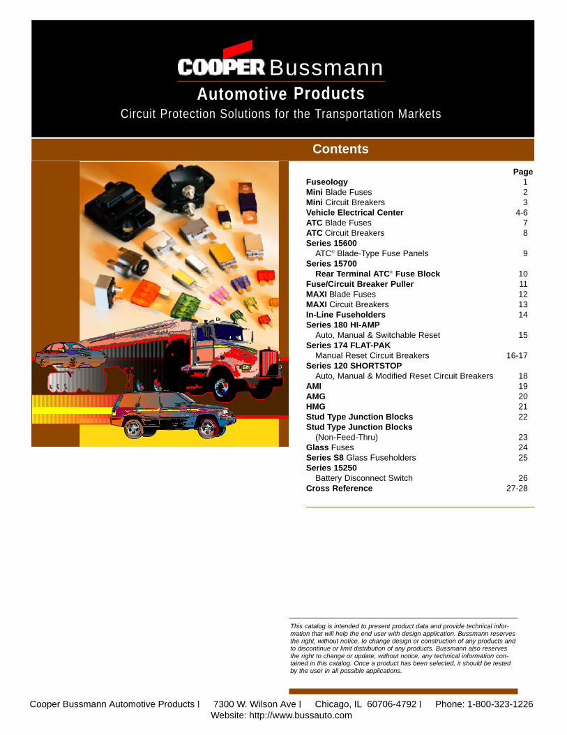
Contents
PageFuseology 1Mini Blade Fuses 2Mini Circuit Breakers 3Vehicle Electrical Center 4-6ATC Blade Fuses 7ATC Circuit Breakers 8Series 15600
ATC® Blade-Type Fuse Panels 9Series 15700
Rear Terminal ATC® Fuse Block 10Fuse/Circuit Breaker Puller 11MAXI Blade Fuses 12MAXI Circuit Breakers 13In-Line Fuseholders 14Series 180 HI-AMP
Auto, Manual & Switchable Reset 15Series 174 FLAT-PAK
Manual Reset Circuit Breakers 16-17Series 120 SHORTSTOP
Auto, Manual & Modified Reset Circuit Breakers 18AMI 19AMG 20HMG 21Stud Type Junction Blocks 22Stud Type Junction Blocks
(Non-Feed-Thru) 23Glass Fuses 24Series S8 Glass Fuseholders 25Series 15250
Battery Disconnect Switch 26Cross Reference 27-28
Cooper Bussmann Automotive Products l 7300 W. Wilson Ave l Chicago, IL 60706-4792 l Phone: 1-800-323-1226Website: http://www.bussauto.com
BussmannProductsAutomotive
Circuit Protection Solutions for the Transportation Markets
Automotive Products
Protection Solutions for the Transportation
Bussmann
1
Basic Overcurrent Technology Bussmann®
Overcurrent devices provide two main purposes in an electrical circuit:1. To protect components, equipment, and associated wiring
from costly damage.2. To isolate sub-systems from the main system once a current
fault has occurred.Fuses and circuit breakers are commonly selected as thepreferred overcurrent device.
FusesThe key component of a fuse is the “element”, a short piece ofmetallic wire or strap made of a material with a relatively low andpredictable melting point. Fuses are current sensitive devices andselected to be the weakest link in the circuit. Circuit protection isprovided when the fuse link melts and safely interrupts theovercurrent demand. The key criteria to judge the performance ofa fuse is the time versus current characteristic curve. This curvecan be used to match the fuse with the anticipated overcurrentload expected in the application.
Thermal Circuit BreakersThe basic components of a thermal circuit breaker are thecomposite alloy reed, two precious metal contacts, and theinterconnecting terminals. When an overcurrent occurs, heat isgenerated as the current flows through the reed causing the reedto deflect and snap open. This separates the contacts and safelyinterrupts the current flow. Two important parameters used tojudge the performance of thermal circuit breakers are the timeversus current characteristic curve, similar to the fuse, along withthe speed at which the contacts snap open. The relative speed atwhich the contacts separate is a measure of the cycle life underelectrical loading demands. Cooper Bussmann - AutomotiveProducts carefully designs its snap acting reed element to insurelong cycle performance for its products.
TYPES OF OVERCURRENT
Any current that exceeds the ampere rating of the fuse or circuitbreaker should be considered an overcurrent. Overcurrent situations are generally classified as either a short circuit or anoverload condition.
Short CircuitShort circuit is a current condition that greatly exceeds the ratingof the device. It is caused when a malfunction or accident createsa break in the normal path allowing electricity to flow directly toground. This shorter current path bypasses the resistance offeredby the circuit components connected in the normal current path. Inthis situation there is virtually no resistance to impede the currentand the current will build to a level where the heat generated cancause insulation and/or equipment breakdown.
OverloadAn overload is an overcurrent that is within the normal currentpath. Overloads occur when the current exceeds the value forwhich the equipment or associated wiring is rated. This typicallyoccurs when too many devices are connected to the circuit orwhen a device connected to the circuit malfunctions. Sustainedoverloads may slowly cause overheating of the wiring and thecomponents. The circuit protection device must open before thesetypes of overloads cause damage.
SELECTING OVERCURRENT PROTECTION
During normal conditions, an overcurrent protection device mustcarry the current without nuisance openings. However, when anoverload or short circuit occurs the device must interrupt theovercurrent and withstand the voltage across the device afterarcing. To properly select an overcurrent device the followingitems must be carefully considered:
• Voltage rating: represents the maximum system voltagepresent in the circuit in which the overcurrent device is installed.The system voltage should not exceed this value for properoperation of the device during an overcurrent event.
• Current rating:This is the amperage value marked on the circuit protectiondevice. The circuit protection device is designed to handle thisvalue under steady operating conditions and at ambienttemperatures near 25°C. Since field applications often deliverloading conditions and ambient temperatures that very from idealnominal settings, it is recommended that circuit designers selectdevice ratings above the nominal circuit current to preventnuisance trips.
• Characteristics of equipment tobe protected/In-rush characteristics: During the operation of protected equipment, system current cansignificantly vary. This is particularly evident when motor or otherinductive loads in the circuit cause large current surges duringstart-up or shut-down. Circuit protection designers should beaware of these surges and/or in-rush characteristics and selectthe overcurrent protection device to either accept or reject thesecurrent fluctuations as desired.
• Available short circuit current:During a fault or short circuit condition the fuse or circuit breakermay receive a burst of current due to a rapid discharge ofavailable supply current into the circuit. Large DC batterysupplies and high current rated electric distribution buses oftenhave this potential for severe short circuits. In these situationsthe current protection device should be rated to safely clearthese instantaneous peak current possibilities.
• Ambient conditions:The time it takes to interrupt the current is dependent upon theambient current temperature characteristics. Ambienttemperature refers to the temperature of the air immediatelysurrounding the circuit protection device. The effective fuse orcircuit breaker ambient temperature to be considered can beappreciably different than the outside room or larger enclosurecontaining the device. This can occur when the device iscontained in a tight area or it is mounted in or near a heatproducing component such as a transformer or resistor. Whenselecting a fuse or circuit breaker at ambient temperaturessignificantly different from the stated nominal temperature, thecircuit designer should adjust the selected overcurrent protectionrating based on the published derating curves.
Fuses — may be preferred when fast response to a short circuitcondition is required or when high available short circuit currentscould occur. Fuses are also less sensitive to high ambienttemperature conditions. Fuse characteristic curves can be used tocarefully size the device to a critical or special application.
Circuit Breakers — may be preferred for mild overload andshort circuit faults. They have a clear advantage of resetability.Four different methods for reset are generally available:• Type I (automatic reset): the circuit breaker cycles continuously
during an overload condition until the overload is removed or corrected.
• Type II (modified reset): the circuit breaker contains an additionalresistive component that causes the device to remain open aslong as power is available.
• Type III (manual reset): the circuit breaker contains a tripindicator button or lever that must be manually activated to returnthe device to normal operation.
• Type III (switchable): same as the manual Type III with the option of allowing the user to disable the circuit using an externaltrip button.
Cooper Bussmann Automotive Products l 7300 W. Wilson Ave l Chicago, IL 60706-4792 l Phone: 1-800-323-1226Website: http://www.bussauto.com
Return to Index
2
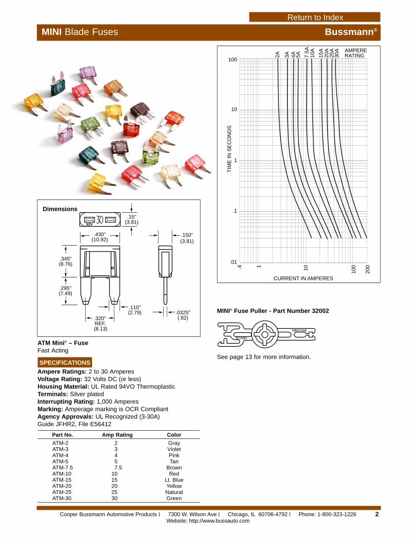
MINI Blade Fuses Bussmann®
ATM Mini® – FuseFast Acting
SPECIFICATIONS
Ampere Ratings: 2 to 30 AmperesVoltage Rating: 32 Volts DC (or less)Housing Material: UL Rated 94VO ThermoplasticTerminals: Silver platedInterrupting Rating: 1,000 AmperesMarking: Amperage marking is OCR CompliantAgency Approvals: UL Recognized (3-30A)Guide JFHR2, File E56412
.430"(10.92)
.15"(3.81)
.320" REF.(8.13)
.295"(7.49)
.345"(8.76)
.110"(2.79) .0325"
(.82)
.150"(3.81)
32V
.4 1 10 100
200
CURRENT IN AMPERES
100
10
1
.1
.01
TIM
E IN
SE
CO
ND
S
AMPERERATING2A 3A 4A 5A 7.
5A10
A
15A
20A
25A
30A
Dimensions
Part No. Amp Rating Color
ATM-2 2 GrayATM-3 3 VioletATM-4 4 PinkATM-5 5 TanATM-7.5 7.5 BrownATM-10 10 RedATM-15 15 Lt. BlueATM-20 20 YellowATM-25 25 NaturalATM-30 30 Green
MINI® Fuse Puller - Part Number 32002
MINI FUSE
MINI CB
See page 13 for more information.
Cooper Bussmann Automotive Products l 7300 W. Wilson Ave l Chicago, IL 60706-4792 l Phone: 1-800-323-1226Website: http://www.bussauto.com
Return to Index
.490"(12.45)
Standard Marking Location
Amperage Marking
1.06"(26.92)
.354"(8.99)
.435"(11.05)
.110" (2.79)
.32" (8.13)
.032"(.81)
.150"(3.81)
.250"(6.35)
3
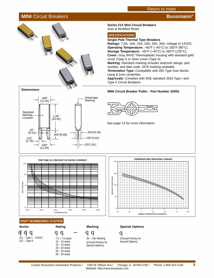
Series 21X Mini Circuit BreakersAuto & Modified Reset
SPECIFICATIONS
Single Pole Thermal Type BreakersRatings: 7.5A, 10A, 15A, 20A, 25A, 30A; Voltage of 14VDC.Operating Temperature: –40°F (–40°C) to 185°F (85°C).Storage Temperature: –40°F (–40°C) to 260°F (125°C).Cover: Gray 94VO Thermoplastic housing with standard goldcover (Type I) or silver cover (Type II).Marking: Standard marking includes amp/volt ratings, partnumber, and date code. OCR marking available.Termination Type: Compatible with 280 Type fuse blocksusing 8.1mm centerline.Approvals: Complies with SAE standard J553 Type I and Type II Circuit Breakers.
PART NUMBERING SYSTEM
Series
qqq2 1
211 – Type I, 14VDC212 – Type II,
Rating
qq –7.5 – 7.5 amps10 – 10 amps 15 – 15 amps 20 – 20 amps25 – 25 amps30 – 30 amps
Marking
qq00 – Std. Marking(Consult Factory forSpecial Options)
Special Options
q(Consult Factory forSpecial Options)
Dimensions
1000
100
10
1
0.1
100% 200% 300% 400% 500% 600%
TRIP TIME VS. PERCENT OF RATED CURRENT
% of Rated Current
Tim
e in
Sec
on
ds
-50
0
50
100
150
200
-25 0 25 50 75 100
TEMPERATURE DERATING CURVES
AMBIENT TEMPERATURE IN DEGREES C
Max
imu
m %
Ho
ld C
urr
ent
MINI FUSE
MINI CB
MINI Circuit Breaker Puller - Part Number 32002
See page 13 for more information.
MINI Circuit Breakers Bussmann®
Cooper Bussmann Automotive Products l 7300 W. Wilson Ave l Chicago, IL 60706-4792 l Phone: 1-800-323-1226Website: http://www.bussauto.com
Return to Index Return to Index
Return to Index
4
Vehicle Electrical Center Bussmann®
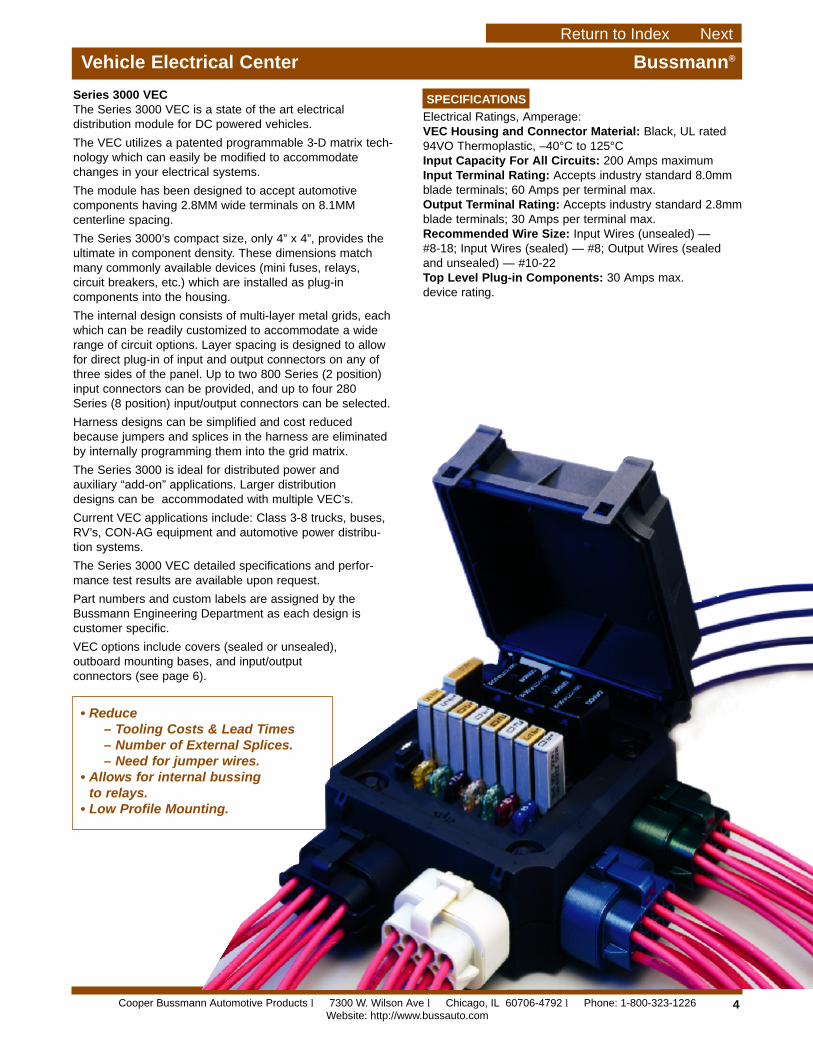
Series 3000 VECThe Series 3000 VEC is a state of the art electricaldistribution module for DC powered vehicles.
The VEC utilizes a patented programmable 3-D matrix tech-nology which can easily be modified to accommodatechanges in your electrical systems.
The module has been designed to accept automotivecomponents having 2.8MM wide terminals on 8.1MMcenterline spacing.
The Series 3000’s compact size, only 4” x 4”, provides theultimate in component density. These dimensions matchmany commonly available devices (mini fuses, relays,circuit breakers, etc.) which are installed as plug-incomponents into the housing.
The internal design consists of multi-layer metal grids, eachwhich can be readily customized to accommodate a widerange of circuit options. Layer spacing is designed to allowfor direct plug-in of input and output connectors on any ofthree sides of the panel. Up to two 800 Series (2 position)input connectors can be provided, and up to four 280Series (8 position) input/output connectors can be selected.
Harness designs can be simplified and cost reducedbecause jumpers and splices in the harness are eliminatedby internally programming them into the grid matrix.
The Series 3000 is ideal for distributed power and auxiliary “add-on” applications. Larger distribution designs can be accommodated with multiple VEC’s.
Current VEC applications include: Class 3-8 trucks, buses, RV’s, CON-AG equipment and automotive power distribu-tion systems.
The Series 3000 VEC detailed specifications and perfor-mance test results are available upon request.
Part numbers and custom labels are assigned by theBussmann Engineering Department as each design is customer specific.
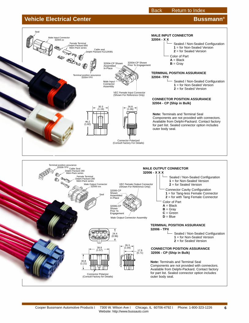
VEC options include covers (sealed or unsealed), outboard mounting bases, and input/output connectors (see page 6).
• Reduce– Tooling Costs & Lead Times– Number of External Splices.– Need for jumper wires.
• Allows for internal bussing to relays.
• Low Profile Mounting.
SPECIFICATIONS
Electrical Ratings, Amperage:VEC Housing and Connector Material: Black, UL rated94VO Thermoplastic, –40°C to 125°CInput Capacity For All Circuits: 200 Amps maximumInput Terminal Rating: Accepts industry standard 8.0mmblade terminals; 60 Amps per terminal max.Output Terminal Rating: Accepts industry standard 2.8mmblade terminals; 30 Amps per terminal max.Recommended Wire Size: Input Wires (unsealed) — #8-18; Input Wires (sealed) — #8; Output Wires (sealedand unsealed) — #10-22Top Level Plug-in Components: 30 Amps max. device rating.
Cooper Bussmann Automotive Products l 7300 W. Wilson Ave l Chicago, IL 60706-4792 l Phone: 1-800-323-1226Website: http://www.bussauto.com
Return to Index Next
5
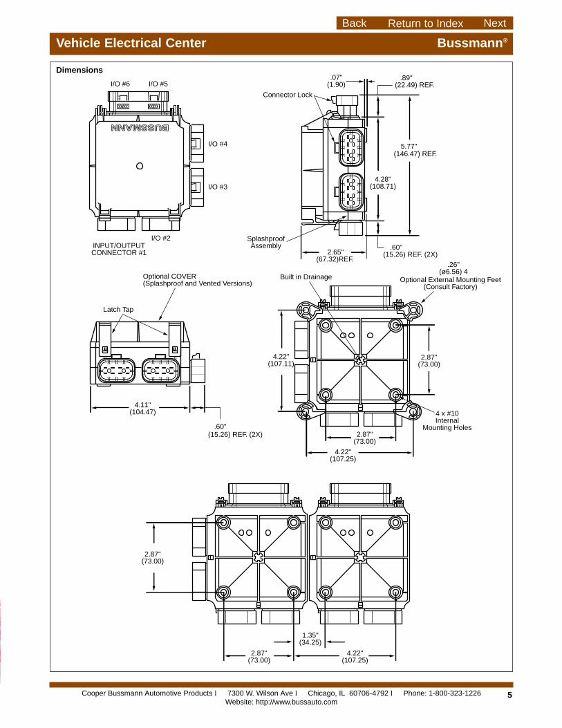
Vehicle Electrical Center Bussmann®
BUSSMANN
2.87"(73.00)
2.87"(73.00)
4 x #10Internal
Mounting Holes
4.22"(107.11)
.07"(1.90)
4.28"(108.71)
(146.47) REF.5.77"
(22.49) REF..89"
2.65"(67.32)REF.
4.22"(107.25)
Built in Drainage
.26"(ø6.56) 4
Optional External Mounting Feet(Consult Factory)
I/O #6
I/O #4
I/O #3
I/O #2
I/O #5
.60"(15.26) REF. (2X)
4.11"(104.47)
.60"(15.26) REF. (2X)
Connector Lock
2.87"(73.00)
2.87"(73.00)
1.35"(34.25)
4.22"(107.25)
SplashproofAssembly
Latch Tap
Optional COVER(Splashproof and Vented Versions)
INPUT/OUTPUTCONNECTOR #1
Dimensions
Cooper Bussmann Automotive Products l 7300 W. Wilson Ave l Chicago, IL 60706-4792 l Phone: 1-800-323-1226Website: http://www.bussauto.com
Return to IndexBack Next
26.8(1.06)
30.3(1.19)
46.2(1.82)
Connector Polarized(Consult Factory For Details)
32004-CP Shown Assembled In-Place
32004-CP Shown Prior To Engagement
VEC Female Input Connector(Shown For Reference Only)
Male Input Connector Assembly
H G F
B C D
24.4(0.96)
26.3(1.04)
17.9(0.71)
39.9(1.57)
30.8(1.21)
•
Connector Polarizer(Consult Factory for Details)
Terminal position assurance32006-TPX
Seal
Male Output Connector 32006-xxx
Female TerminalDelphi Packard 280Metri-Pack series
Cable SealDelphi Packard 280Metri-Pack series
6
Vehicle Electrical Center Bussmann®
Terminal position assurance32004-TPX
Seal
Male Input Connector 32004-xx
Female TerminalDelphi Packard 800Metri-Pack series
Cable sealDelphi Packard #12129381
TERMINAL POSITION ASSURANCE32006 - TPX
Sealed / Non-Sealed Configuration1 = for Non-Sealed Version2 = for Sealed Version
Sealed / Non-Sealed Configuration1 = for Non-Sealed Version2 = for Sealed Version
Connector Cavity Configuration1 = for Tang-less Female Connector2 = for with Tang Female Connector
Color of PartA = BlackB = GrayC = GreenD = Blue
MALE OUTPUT CONNECTOR32006 - X X X
MALE INPUT CONNECTOR32004 - X X
Sealed / Non-Sealed Configuration1 = for Non-Sealed Version2 = for Sealed Version
Color of PartA = BlackB = Gray
TERMINAL POSITION ASSURANCE32004 -TPX
CONNECTOR POSITION ASSURANCE32004 - CP (Ship in Bulk)
Sealed / Non-Sealed Configuration1 = for Non-Sealed Version2 = for Sealed Version
CONNECTOR POSITION ASSURANCE32006 - CP (Ship in Bulk)
Note: Terminals and Terminal SealComponents are not provided with connectors.Available from Delphi-Packard. Contact factoryfor part list. Sealed connector option includesouter body seal.
Note: Terminals and Terminal SealComponents are not provided with connectors.Available from Delphi-Packard. Contact factoryfor part list. Sealed connector option includesouter body seal.
Male Output Connector Assembly
VEC Female Output Connector(Shown For Reference Only)
32006-CP Shown Assembled In-Place
32006-CP Shown Prior To Engagement
Cooper Bussmann Automotive Products l 7300 W. Wilson Ave l Chicago, IL 60706-4792 l Phone: 1-800-323-1226Website: http://www.bussauto.com
Return to IndexBack
7
ATC Blade Fuses Bussmann®
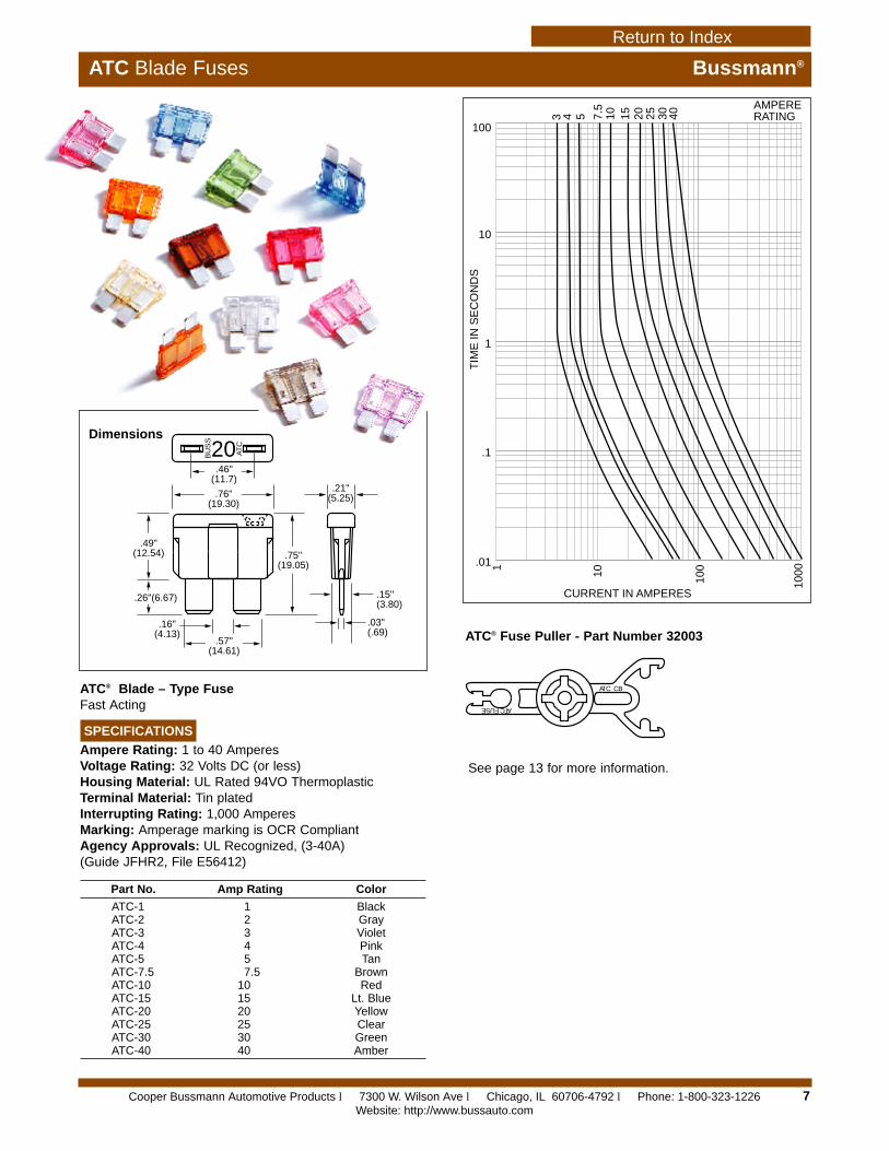
ATC® Blade – Type FuseFast Acting
SPECIFICATIONS
Ampere Rating: 1 to 40 AmperesVoltage Rating: 32 Volts DC (or less)Housing Material: UL Rated 94VO ThermoplasticTerminal Material: Tin platedInterrupting Rating: 1,000 AmperesMarking: Amperage marking is OCR CompliantAgency Approvals: UL Recognized, (3-40A) (Guide JFHR2, File E56412)
BU
SS
ATC20
.15"(3.80)
.03"(.69)
.46"(11.7)
.76"(19.30)
.49"(12.54)
.26"(6.67)
.16"(4.13)
.57"(14.61)
.75"(19.05)
.21"(5.25)
1
10 100
1000
CURRENT IN AMPERES
100
10
1
.1
.01
TIM
E IN
SE
CO
ND
S
10 15 20 25 30
AMPERERATING7.
5
543 40
Dimensions
Part No. Amp Rating Color
ATC-1 1 BlackATC-2 2 GrayATC-3 3 VioletATC-4 4 PinkATC-5 5 TanATC-7.5 7.5 BrownATC-10 10 RedATC-15 15 Lt. BlueATC-20 20 YellowATC-25 25 ClearATC-30 30 GreenATC-40 40 Amber
ATC® Fuse Puller - Part Number 32003
ATC FUSE
ATC CB
See page 13 for more information.
Cooper Bussmann Automotive Products l 7300 W. Wilson Ave l Chicago, IL 60706-4792 l Phone: 1-800-323-1226Website: http://www.bussauto.com
Return to Index

1.17"(29.82)
1.08"(27.40)
.21"(5.25) TYP
.25" (6.40) TYP
.03" (0.80) TYP
.57"(14.50) TYP
.16"(4.00)
.10"(2.50)
.20"(5.00)
.31"(8.00)
.08"(2.00)
.25"(6.30)
.43"(11.00)
.11"(2.80) TYP
.25"(6.35)
3
1 2
4
Reset Button(Tripped)
Amperage Marking
StandardMarkingLocation
ATC
FUSE
ATC CB
.75"(19.00)
Dimensions - Terminal Option 0
8
1000
100
10
1
0.1100% 200% 300% 400% 500% 600%
TRIP TIME VS. PERCENT OF RATED CURRENT
% of Rated Current
Tim
e in
Sec
on
ds
-50
0
50
100
150
200
-25 0 25 50 75 100
TEMPERATURE DERATING CURVES
AMBIENT TEMPERATURE IN DEGREES C
Max
imu
m %
Ho
ld C
urr
ent
Series 22X ATC® Circuit BreakersAuto & Modified Reset
SPECIFICATIONS
Single Pole Thermal Type BreakersRatings: 7.5A, 10A, 15A, 20A, 25A, 30A; Voltage of 14VDC; 24VDC on 223 Series.Operating Temperature: –40°F (–40°C) to 185°F (85°C).Storage Temperature: –40°F (–40°C) to 260°F (125°C).Cover: Gray 94VO Thermoplastic housing with standardgold cover (Type I) or silver cover (Type II and Type III).Marking: Standard marking includes amp/volt ratings, partnumber, and date code. Type III Reset Buttons are color-coded to amperage ratings. OCR marking is available.Termination Type: Compatible with 280 Type or ATC fuse blocks.Approvals: Complies with the requirements of SAE standard J553 Type I, Type II, and Type III Circuit Breakers.
PART NUMBERING SYSTEM
Series
qqq2 2
221 – Type I, 14VDC222 – Type II,14VDC223 – Type III, 24VDC
Rating
qq –7.5 – 7.5 amps10 – 10 amps 15 – 15 amps20 – 20 amps25 – 25 amps30 – 30 amps
Terminal
q0 – ATC Fuse, 4mm Insertion Depth1 – 16.2mm Centerline 2802 – 8.1mm Centerline 280 (MINI)3 – ATC Fuse, Delphi Packard
Autofuse Block (e.g. 12004943)4 – ATC Fuse, Blocks with Raised
Shrouds, 6.4mm Insertion Depth
Marking
q00 – Std. Marking
Terminal Options ATC® Circuit Breaker PullerPart Number 32003
See page 13 for moreinformation.
ATC Circuit Breakers Bussmann®
Cooper Bussmann Automotive Products l 7300 W. Wilson Ave l Chicago, IL 60706-4792 l Phone: 1-800-323-1226Website: http://www.bussauto.com
Return to Index
9
No. of Fuses &/or CircuitBreaker Positions
q – qq –0
04-20
q – qq/qq –2
Left Side Right Side04-16 04-16
(max. combination of 20)
Series
qqqq1 5 6 0
0 – Single Stud, Single Supply Circuit 2 – Double Stud, Split Supply Circuits
"L"
"C"
1.06"(26.92)
.62"(15.75)
.62" TYP (15.75)
.80"(20.32)
.250" QC (COPPER ALLOY - TIN PLATED)
(15600 -10-20 SHOWN)
.22" DIA. HOLE WITH .41 x .12DEEP C'BORE (4X)
(12) .250" QC TERMINALS W/COMMON WIRING STUD, ADD 1.300" TO "L" FOR OVERALL LENGTH
"L"
"C"
3.37"(85.59)
2.50"(63.50)
1.06"(26.92)
1.22"(30.98) (15602-04/08-20 SHOWN)
15600 Series 15602 Series
Ground Terminal Base Option
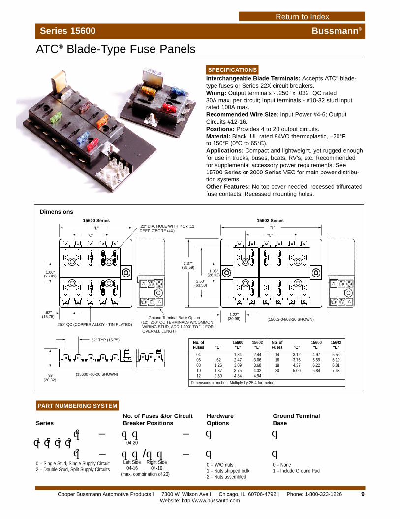
Series 15600 Bussmann®
SPECIFICATIONS
Interchangeable Blade Terminals: Accepts ATC® blade-type fuses or Series 22X circuit breakers.Wiring: Output terminals - .250" x .032" QC rated 30A max. per circuit; Input terminals - #10-32 stud inputrated 100A max.Recommended Wire Size: Input Power #4-6; OutputCircuits #12-16.Positions: Provides 4 to 20 output circuits.Material: Black, UL rated 94VO thermoplastic, –20°F to 150°F (0°C to 65°C).Applications: Compact and lightweight, yet rugged enoughfor use in trucks, buses, boats, RV’s, etc. Recommended for supplemental accessory power requirements. See 15700 Series or 3000 Series VEC for main power distribu-tion systems.Other Features: No top cover needed; recessed trifurcatedfuse contacts. Recessed mounting holes.
ATC® Blade-Type Fuse Panels
PART NUMBERING SYSTEM
HardwareOptions
q
q0 – W/O nuts1 – Nuts shipped bulk2 – Nuts assembled
Ground TerminalBase
q
q0 – None1 – Include Ground Pad
No. of 15600 15602 No. of 15600 15602Fuses “C” “L” “L” Fuses “C” “L” “L”
04 – 1.84 2.44 14 3.12 4.97 5.5606 .62 2.47 3.06 16 3.76 5.59 6.1908 1.25 3.09 3.68 18 4.37 6.22 6.8110 1.87 3.75 4.32 20 5.00 6.84 7.4312 2.50 4.34 4.94
Dimensions in inches. Multiply by 25.4 for metric.
Dimensions
Cooper Bussmann Automotive Products l 7300 W. Wilson Ave l Chicago, IL 60706-4792 l Phone: 1-800-323-1226Website: http://www.bussauto.com
Return to Index

10
Series 15700 Bussmann®
No. ofPositions
q – qq –1
16
q – qq/qq –2Left Side Right Side04-12 04-12
(max. total of 16)(increments of 4)
For 8-24 pole option consult factory.
Series
qqqq1 5 7 0
1 – Single Stud, Single Supply Circuit2 – Double Stud, Split Supply Circuit
PART NUMBERING SYSTEM
HardwareOptions
q
q0 – W/O nuts1 – Nuts shipped bulk2 – Nuts assembled
CoverOption
q
q0 – No cover1 – w/ fuse cover2 – w/ CB cover
Output ClipOption
q
q0 – No clips1 – with clips
Terminal Lock Option
q
q0 – No locks1 – with locks
Rear Terminal ATC® Fuse Block
FUSE PANEL
BUSSMANN
94.0
70.1
96.8
75.0
87.8 68.4
16.6
19.1 49.5
9.259.3
COOPER Bussman
1.4
5.5
16.3 8.360.0
15.0
6.1
RTA Connector Removal Tool
RTA Lock Release Tool
Bussmann
4.0 TYP6.0 TYP
A
15.030.0
90.0
4.0
SPECIFICATIONS
Blade Terminals: Accepts ATC® blade-type fuses or Series220 ATC® circuit breakers.Power Input: 1/4-20 stud for ring terminal. 200 amp max. input.Positions: Provides 8 to 24 output circuits.Material: 94VO Thermoplastic.Ambient Temperature: –40°C to 125°C.Recommended Wire Size: Input Power #4-6; OutputCircuits #10-16.Applications: Power distribution system for trucks, buses,boats, RV’s etc. 15702-product line allows for two separatepowered circuits.Other Features: Splash resistant cover. Rear terminalwiring for through panel mounting. No wiring or connectionsexposed to front of panel. Secondary lock feature for secur-ing of output terminals. Packard style output terminals canbe removed from 15700 product with use of special tool.Does not require distribution block removal for replacementor rearrangement of wires.
Accepts Delphi Pack-Con Terminals in output positions.Consult factory for other terminal options and information.Output terminals are not supplied with fuse block.
For connector removal tools,consult factory
.
Cooper Bussmann Automotive Products l 7300 W. Wilson Ave l Chicago, IL 60706-4792 l Phone: 1-800-323-1226Website: http://www.bussauto.com
Return to Index
11
Fuse/Circuit Breaker Puller Bussmann®
Series 32000 Series Automotive Fuse and Circuit Breaker Extraction Tool
FEATURES / BENEFITS
• Custom Configurable DesignGet Only the Extractors You Need
• Common Platform for any StyleEliminates Design Changes When ProtectionRequirements Change
• Center Snap-Lock Mounting HoleEasy Mounting Using Simple Split-Ball Snap-Lock Post
• Positive Stop Locking ActionTight Grip Allows Devices to be Removed and Inserted
• High Temperature Resilient Nylon 6/6 (105°C)
PART NUMBERING SYSTEM
Series
qqqq3 2 0 0
Configuration
qTop Right Bottom Left
0 – MINI CB MINI FUSE ATC CB ATC FUSE1 – MINI CB BLANK ATC CB BLANK2 – MINI CB BLANK MINI FUSE BLANK3 – ATC CB BLANK ATC FUSE BLANK
MIN
I CB
MIN
I CB
MINI FUSE
ATC FUSE
ATC C
B
ATC C
B
17.00
R8.25
25.00
30.00
30.00
7.90
33.00
A
A
R6.00
8.6
30.00
10.00 1.60
Ø 4.00
32001 32002 32003
32000
SCETION A-A
ATC
FU
SE
ATC C
B
MIN
I FU
SE
MIN
I CB
Dimensions
Cooper Bussmann Automotive Products l 7300 W. Wilson Ave l Chicago, IL 60706-4792 l Phone: 1-800-323-1226Website: http://www.bussauto.com
Return to Index
12
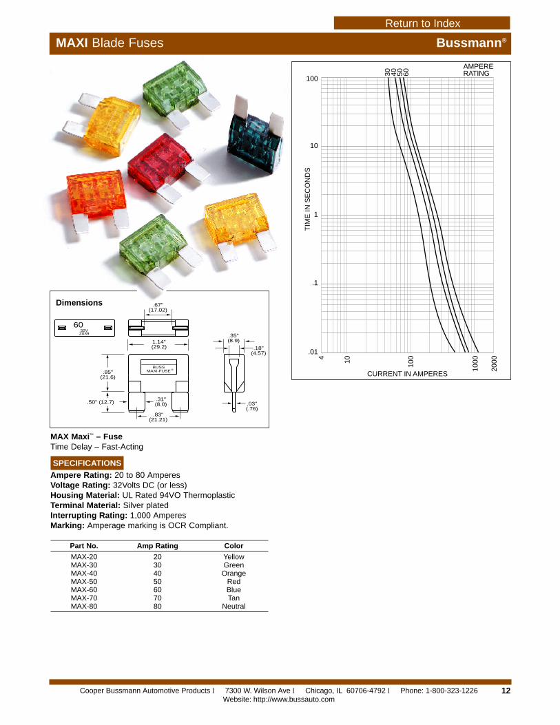
MAXI Blade Fuses Bussmann®
MAX Maxi™ – FuseTime Delay – Fast-Acting
SPECIFICATIONS
Ampere Rating: 20 to 80 AmperesVoltage Rating: 32Volts DC (or less)Housing Material: UL Rated 94VO ThermoplasticTerminal Material: Silver platedInterrupting Rating: 1,000 AmperesMarking: Amperage marking is OCR Compliant.
BUSSMAXI-FUSE ®
32VZ039
60
.67"(17.02)
1.14"(29.2)
.85"(21.6)
.50" (12.7)
.83"(21.21)
.31"(8.0)
.35"(8.9)
.18"(4.57)
.03"(.76)
4 10 100
1000
2000
CURRENT IN AMPERES
100
10
1
.1
.01
TIM
E IN
SE
CO
ND
S
30
AMPERERATING40 50 60
Dimensions
Part No. Amp Rating Color
MAX-20 20 YellowMAX-30 30 GreenMAX-40 40 OrangeMAX-50 50 RedMAX-60 60 BlueMAX-70 70 TanMAX-80 80 Neutral
For complete specification data, call Bussmann Information Fax ~ 314.527.1450Cooper Bussmann Automotive Products l 7300 W. Wilson Ave l Chicago, IL 60706-4792 l Phone: 1-800-323-1226Website: http://www.bussauto.com
Return to Index
PART NUMBERING SYSTEM
Series
qqq1 9
191 – Auto Reset (12 VDC)192 – Modified Reset (12 VDC)193 – Manual Reset (24 VDC)194 – Auto Reset (24 VDC)195 – Modified Reset (24 VDC)
Rating
qq –08 – 8 amps10 – 10 amps15 – 15 amps20 – 20 amps25 – 25 amps30 – 30 amps35 – 35 amps40 – 40 amps50 – 50 amps
Terminal
qq01 – MAXI
Cover
q –M – Metal*P – Plastic
Button(193 Series Only)
qBlank – No button1 – Black2 – White
Marking
qConsult factoryfor special markings.
* Metal cover aids heat dissipation.Mandatory for Modified Resets (192 & 195).Recommended, but not mandatory on Auto Resets (191 & 194).Not available on Manual Resets (193).
13
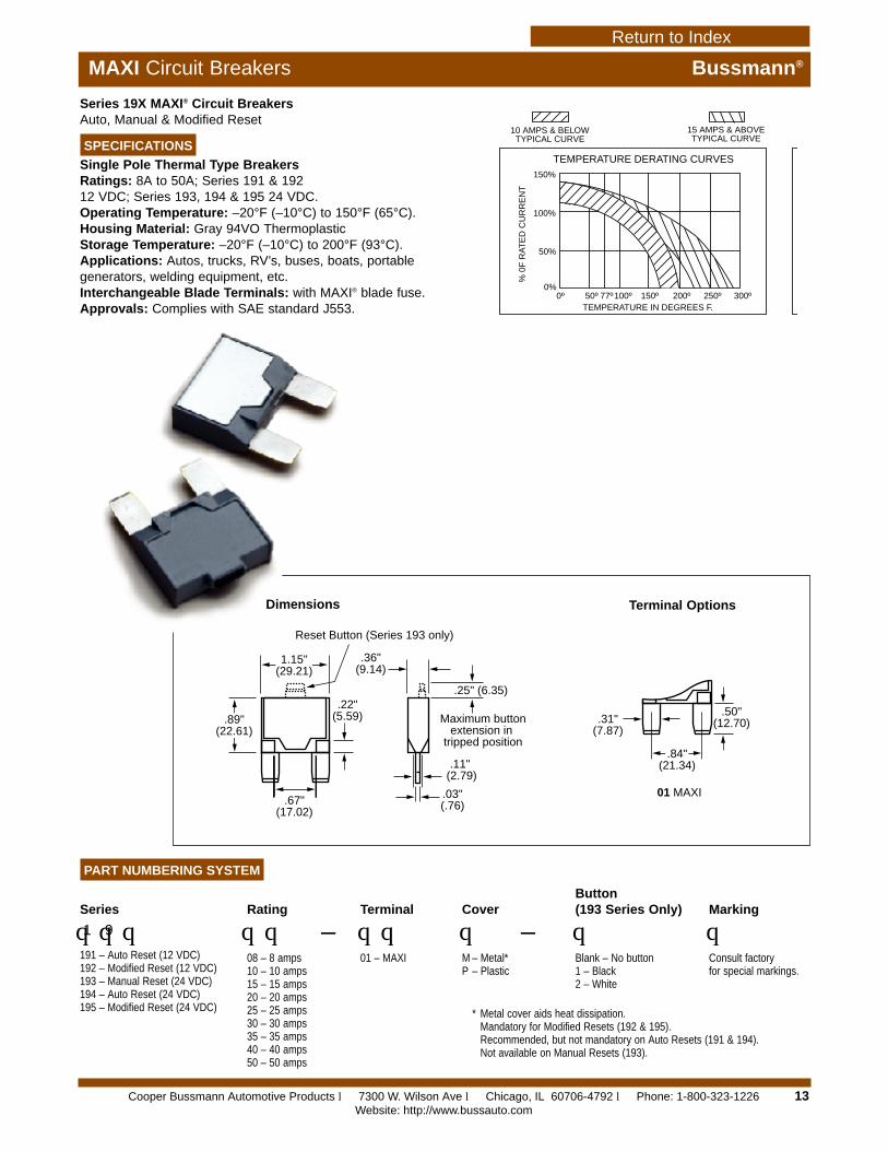
MAXI Circuit Breakers Bussmann®
Series 19X MAXI® Circuit BreakersAuto, Manual & Modified Reset
SPECIFICATIONS
Single Pole Thermal Type BreakersRatings: 8A to 50A; Series 191 & 192 12 VDC; Series 193, 194 & 195 24 VDC.Operating Temperature: –20°F (–10°C) to 150°F (65°C).Housing Material: Gray 94VO ThermoplasticStorage Temperature: –20°F (–10°C) to 200°F (93°C).Applications: Autos, trucks, RV’s, buses, boats, portablegenerators, welding equipment, etc.Interchangeable Blade Terminals: with MAXI® blade fuse.Approvals: Complies with SAE standard J553.
150%
100%
50%
0%
% 0
F R
ATE
D C
UR
RE
NT
50º 77º100º 150º 200º 250º 300º0ºTEMPERATURE IN DEGREES F.
TEMPERATURE DERATING CURVES
10 AMPS & BELOWTYPICAL CURVE
15 AMPS & ABOVETYPICAL CURVE
1.15"(29.21)
.89"(22.61)
.22"(5.59)
.67"(17.02)
.36"(9.14)
.25" (6.35)
.11" (2.79)
.03"(.76)
Reset Button (Series 193 only)
Maximum buttonextension in
tripped position
.31"(7.87)
.84"(21.34)
.50"(12.70)
01 MAXI
Terminal OptionsDimensions
Cooper Bussmann Automotive Products l 7300 W. Wilson Ave l Chicago, IL 60706-4792 l Phone: 1-800-323-1226Website: http://www.bussauto.com
Return to Index
3.35"
6.70" 6.70"
1.37"
.265" DIA. HOLE
1.56"
4.75" 4.75"
.25" .25"
.59"
.41"
.410"
1"
.290"
.250"(TYP/ 2)
4"4" 1.25"
.375"
.343".500"
.906"
.157"
.363".682"
.343"
1"
.140"
4"(TYP/ 2)
4"4" 1.12"
.375"
.296".500"
.906"
.140"
.364".781"
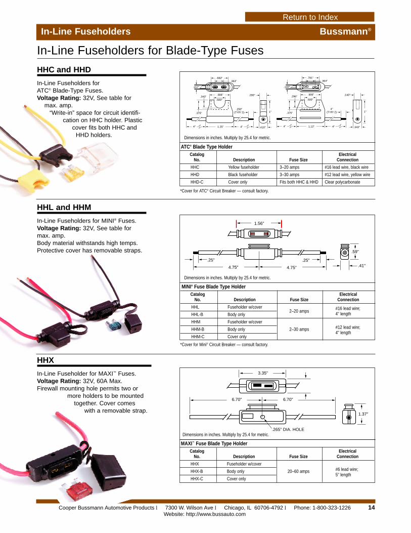
In-Line Fuseholders Bussmann®
In-Line Fuseholders for Blade-Type Fuses
MINI® Fuse Blade Type HolderCatalog Electrical
No. Description Fuse Size Connection
HHL Fuseholder w/cover2–20 amps
#16 lead wire;HHL-B Body only 4" length
HHM Fuseholder w/cover
2–30 amps #12 lead wire;HHM-B Body only4" length
HHM-C Cover only
MAXI™ Fuse Blade Type HolderCatalog Electrical
No. Description Fuse Size Connection
HHX Fuseholder w/cover
20–60 amps #6 lead wire;HHX-B Body only5" length
HHX-C Cover only
ATC® Blade Type HolderCatalog Electrical
No. Description Fuse Size Connection
HHC Yellow fuseholder 3–20 amps #16 lead wire, black wire
HHD Black fuseholder 3–30 amps #12 lead wire, yellow wire
HHD-C Cover only Fits both HHC & HHD Clear polycarbonate
Dimensions in inches. Multiply by 25.4 for metric.
Dimensions in inches. Multiply by 25.4 for metric.
*Cover for ATC® Circuit Breaker — consult factory.
*Cover for Mini® Circuit Breaker — consult factory.
Dimensions in inches. Multiply by 25.4 for metric.
HHC and HHD
In-Line Fuseholders for ATC® Blade-Type Fuses.Voltage Rating: 32V, See table for
max. amp.“Write-in” space for circuit identifi-
cation on HHC holder. Plasticcover fits both HHC and
HHD holders.
HHL and HHM
In-Line Fuseholders for MINI® Fuses.Voltage Rating: 32V, See table formax. amp.Body material withstands high temps.Protective cover has removable straps.
HHX
In-Line Fuseholder for MAXI™ Fuses.Voltage Rating: 32V, 60A Max.Firewall mounting hole permits two or
more holders to be mountedtogether. Cover comes
with a removable strap.
14Cooper Bussmann Automotive Products l 7300 W. Wilson Ave l Chicago, IL 60706-4792 l Phone: 1-800-323-1226Website: http://www.bussauto.com
Return to Index
15
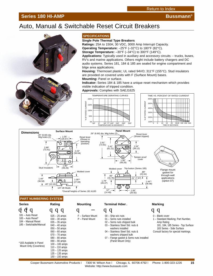
Series 180 HI-AMP Bussmann®
SPECIFICATIONS
Single Pole Thermal Type BreakersRatings: 25A to 150A; 30 VDC, 3000 Amp Interrupt Capacity.Operating Temperature: –25°F (–32°C) to 180°F (82°C).Storage Temperature: –30°F (–34°C) to 300°F (149°C).Applications: Typically used in auxiliary and accessory circuits -- trucks, buses,RV’s and marine applications. Others might include battery chargers and DCaudio systems. Series 181, 184 & 185 are sealed for engine compartment andbilge area applications.Housing: Thermoset plastic; UL rated 94VO; 311°F (155°C). Stud insulatorsare provided on covered units with F (Surface Mount) bases.Mounting: Panel or surface.Indicator: Series 184 & 185 have a unique reset mechanism which providesvisible indication of tripped condition.Approvals: Complies with SAEJ1625
PART NUMBERING SYSTEM
Series
qqq1 8
181 – Auto Reset183 – Auto Reset*184 – Manual Reset185 – Switchable/Manual
Rating
qqq025 – 25 amps030 – 30 amps035 – 35 amps040 – 40 amps050 – 50 amps060 – 60 amps070 – 70 amps080 – 80 amps090 – 90 amps100 – 100 amps110 – 110 amps120 – 120 amps135 – 135 amps150 – 150 amps
Mounting
q –F – Surface MountP – Panel Mount
Terminal Hdwr .
qq00 – Ship w/o nuts01 – Sems nuts installed02 – Sems nuts shipped bulk03 – Stainless Steel Std. nuts &
washers installed04 – Stainless Steel Std. nuts &
washers shipped bulk07 – Flange gasket & Sems nuts installed
(Panel Mount Only)
Marking
qq0 – Blank cover1 – Standard Marking; Part Number,
Amp Rating181, 184, 185 Series - Top Surface183 Series - Side Surface
Consult factory for special markings.
600%
500%
500200100403020151050
400%
300%
200%
200%
150%
100%
50%
0% 100%
TIME VS. PERCENT OF RATED CURRENT
TIME IN SECONDS
% 0
F R
ATE
D C
UR
RE
NT
% 0
F R
ATE
D C
UR
RE
NT
-50º 50º 77º 100º 150º 200º 250º0ºTEMPERATURE IN DEGREES F.
TEMPERATURE DERATING CURVES
Auto, Manual & Switchable Reset Circuit Breakers
RESET
1.05"(26.67)
2.23"(56.64)
2.89"(73.41)
1.44"(36.58) 1.79"
(45.47)
.66"(16.76)
1.09"*(27.69)
.40" (10.16)
1.90"(48.26)Stud insulators
.26" (6.60) dia.Mtg.holes (2) Reset lever
(Shown inoperatingposition)
.26" (6.60) dia. Mtg.holes (2) Reset lever(Shown tripped)
1/4"-28 Studs
Molded coverMolded cover
*Overall heights of Series 181 &183
Trip button (Series 185)
.57"(14.49)
1.06"(26.92)
.31" (7.87)
.89"(22.61)
1.44"*(36.58)
Tamper proofcover1.90"
(48.26)
2.91"(73.91)
2.41"(61.21)
1.54"(39.12)
Surface Mount Panel Mount
Flange mountgasket for
through-wallapplications(option 07)
Dimensions
*183 Available in PanelMount Only (Coverless)
Cooper Bussmann Automotive Products l 7300 W. Wilson Ave l Chicago, IL 60706-4792 l Phone: 1-800-323-1226Website: http://www.bussauto.com
Return to Index
16
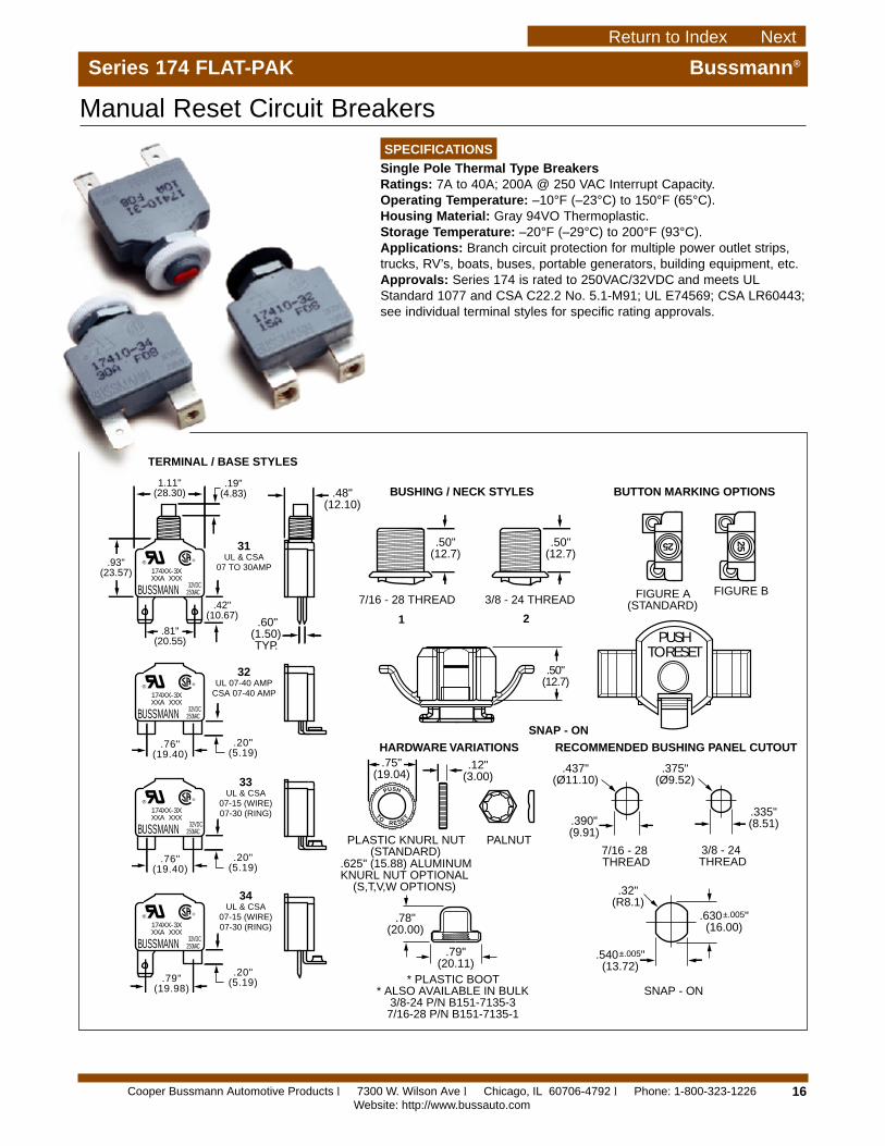
Series 174 FLAT-PAK Bussmann®
® ®
174XX-3XXXA XXX
BUSSMANN 32 VDC250 VAC
® ®
174XX-3XXXA XXX
BUSSMANN 32 VDC250 VAC
® ®
174XX-3XXXA XXX
BUSSMANN 32 VDC250 VAC
® ®
174XX-3XXXA XXX
BUSSMANN 32VDC250 VAC
TERMINAL / BASE STYLES
BUSHING / NECK STYLES BUTTON MARKING OPTIONS
FIGURE A(STANDARD)
HARDWARE VARIATIONSSNAP - ON
SNAP - ON
PLASTIC KNURL NUT(STANDARD)
PALNUT
* PLASTIC BOOT* ALSO AVAILABLE IN BULK
3/8-24 P/N B151-7135-37/16-28 P/N B151-7135-1
RECOMMENDED BUSHING PANEL CUTOUT
FIGURE B
31UL & CSA
07 TO 30AMP
32UL 07-40 AMP
CSA 07-40 AMP
33UL & CSA
07-15 (WIRE)07-30 (RING)
34UL & CSA
07-15 (WIRE)07-30 (RING)
7/16 - 28 THREAD 3/8 - 24 THREAD
7/16 - 28 THREAD
3/8 - 24 THREAD
TOR ESET
.75"(19.04)
.12"(3.00)
.390"(9.91)
.437"(Ø11.10)
.375"(Ø9.52)
.335"(8.51)
.32"(R8.1)
.630 "(16.00)
±.005
.540 "(13.72)
±.005
.50"(12.7)
.50"(12.7)
.48"(12.10)
.60"(1.50) TYP.
1.11"(28.30)
.19"(4.83)
.93"(23.57)
.81"(20.55)
.42"(10.67)
.76"(19.40)
.79"(19.98)
.20"(5.19)
.76"(19.40)
.20"(5.19)
.20"(5.19)
PUSH
.78"(20.00)
.79"(20.11)
PUSHTO RESET
.50"(12.7)
25 25
.625" (15.88) ALUMINUMKNURL NUT OPTIONAL
(S,T,V,W OPTIONS)
1 2
SPECIFICATIONS
Single Pole Thermal Type BreakersRatings: 7A to 40A; 200A @ 250 VAC Interrupt Capacity.Operating Temperature: –10°F (–23°C) to 150°F (65°C).Housing Material: Gray 94VO Thermoplastic.Storage Temperature: –20°F (–29°C) to 200°F (93°C).Applications: Branch circuit protection for multiple power outlet strips,trucks, RV’s, boats, buses, portable generators, building equipment, etc.Approvals: Series 174 is rated to 250VAC/32VDC and meets ULStandard 1077 and CSA C22.2 No. 5.1-M91; UL E74569; CSA LR60443;see individual terminal styles for specific rating approvals.
Manual Reset Circuit Breakers
Cooper Bussmann Automotive Products l 7300 W. Wilson Ave l Chicago, IL 60706-4792 l Phone: 1-800-323-1226Website: http://www.bussauto.com
Return to Index Next
17
PART NUMBERING SYSTEM
Series
qqq1 7 4
174 – Type III250 VAC/32VDCManualReset
Rating
qq– q307 – 7 amps08 – 8 amps10 – 10 amps15 – 15 amps20 – 20 amps25 – 25 amps30 – 30 amps35 – 35 amps*40 – 40 amps*
Terminal/Base
q1 – .25" Quick
Connect2 – 10-32 screw -
90° bend3 – 6-32 screw -
90° bend4 – .25" Quick
Connect with 6-32 screw - 90° bend
Bushing/Neck
q1 – 7/16-28
thread2 – 3/8-24
thread3 – Snap-on
Button
qA – White w/no
markingB – Red w/no
markingC – Black w/no
marking**D – White w/amp
marking Fig. A
E – White w/ampmarking Fig. B
F – Red w/ampmarking Fig. A
G – Red w/ampmarking Fig. B
Hdwr. Pkg.
q1 – Pack bulk
(standard)2 – Assemble to
bushing3 – No hardware
included
Bushing Hdwr.
q –A – White plastic self-lock
knurled nut B – Black plastic self-lock
knurled nutC – White plastic self-lock
knurled nut & zinc platedpalnut
D – Black plastic self-lockknurled nut & zinc platedpalnut
E – No bushing hardwarerequired
F – Zinc plated palnutG – Boot & zinc plated palnutS – Knurlnut, palnut, black
nameplate w/white “Push-to-Reset”
T – Knurlnut, palnut, whitenameplate w/black “Push-to-Reset”
V – Knurlnut and white nameplatew/black “Push-to-Reset”
W – Knurlnut and black nameplatew/white “Push-to-Reset”
Special Options
qq0 – No hardware1 – Bulk brass
screws for screwterminals
2 – Bulk brassscrews and lock-washers forscrew terminals
3 – Assembled brassscrews for screwterminals
4 – Assembled brassscrews and lock-washers forscrew terminals
Series 174 FLAT-PAK Bussmann®
TEMPERATURE IN DEGREES F°(TEMPERATURE IN DEGREES C°)
TIME IN SECONDS
% 0
F R
ATE
D C
UR
RE
NT
% 0
F R
ATE
D C
UR
RE
NT
0°
0 5 10 15 20 30 40 50 100 150 200 400 600
50° 77° 100° 150° 200° 250° 300°(-18°) (10°) (25°) (38°) (65°) (93°) (121°) (149°)
0%
100%
200%
300%
400%
500%
50%
100%
150%
200%
Temperature Derating Curves for 7-40 Amp. Circuit Breakers174 SERIES TEMP. VS. CURRENT CURVES
TIME vs. Percent of Rated Current Curves for 7-40 Amp. Circuit Breakers174 SERIES TRIP CURVES
10 AMP & BELOWTYPICAL CURVE
COMMON CURVEALL VALUES
15 AMP & BELOWTYPICAL CURVE
**No marking availableon Black
*#2 Terminal Style Only.
Cooper Bussmann Automotive Products l 7300 W. Wilson Ave l Chicago, IL 60706-4792 l Phone: 1-800-323-1226Website: http://www.bussauto.com
Return to IndexBack
18
.69"(17.5)
.69"(17.5)
.69"(17.5)
.56"(14.2)
.37" (9.4)
.56"(14.2)
.66"(16.8)
.66"(16.8) .41"
(10.3)
Two 10-32 studs:.66" (AUX); .56" (BAT)
A
Two 10-32 studs:.56" (AUX & BAT)
B
Two 10-32 studs:.66" (AUX & BAT)
C
Two .25" Q.C. (AUX & BAT)
D
.56"(14.2)
.41"(10.3)
.69"(17.5) .69"
(17.5)
.99"(25.2)
Double .25" Q.C. (AUX);One 10-32 stud (BAT)
H
Two 10-32 studs(AUX & BAT)
L
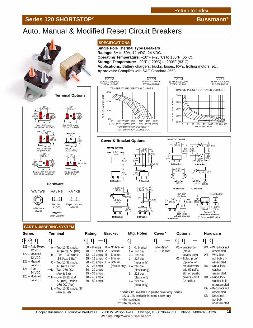
Series 120 SHORTSTOP® Bussmann®
SPECIFICATIONS
Single Pole Thermal Type BreakersRatings: 8A to 50A; 12 VDC; 24 VDC.Operating Temperature: –10°F (–23°C) to 150°F (65°C).Storage Temperature: –20°F (–29°C) to 200°F (93°C).Applications: Battery chargers, trucks, buses, RV’s, trolling motors, etc.Approvals: Complies with SAE Standard J553.
Auto, Manual & Modified Reset Circuit Breakers
1.24"(31.5)
1.27"(32.3)
1.27"(32.3)
1.24"(31.5)
1.24"(31.5)
1.24"(31.5)
1.27"(32.2)
1.27"(32.2)
1.56"(39.6)
1.56"(39.6)
1.56"(39.6)
.79"(20.1)
.79"(20.1)
.69"(17.5)
.69"(17.5)
.79"(20.1)
1.56"(39.6)
1.56"(39.6)
.64"(16.3)
.62"(15.7)
.69"(17.5)
.83"(21.1)
O Bracket
O Bracket
A Bracket
A Bracket
B Bracket C Bracket
E Bracket
Series 123O Bracket w/reset
B Bracket C Bracket
.38" (9.6)
.37" (9.4)
.79"(20.1)
.38" (9.6)
METAL COVER
PLASTIC COVER
1.27"(32.3)
.83"(21.1)
.62"(15.7)
.83"(21.1)
.37" (9.4)
.83"(21.1)
.06"(1.5)
.12" (3.0)dia. boss
.62" (15.7)Ref. (Typ)
w/base attached
Reset button*
BAT AUX
BATAUX
BAT AUX
( * Reset on BAT side)
Cover & Bracket Options
Terminal Options
Hardware
PART NUMBERING SYSTEM
Series
qqq1 2
121 – Auto Reset12 VDC
122 – Modified 12 VDC
123 – Manual 24 VDC
124 – Auto 24 VDC
125 – Modified 24 VDC
Terminal
qA – Two 10-32 studs;
.66 (Aux), .56 (Bat)B – Two 10-32 studs;
.56 (Aux & Bat)C – Two 10-32 studs;
.66 (Aux & Bat)***D – Two .250 QC;
(Aux & Bat)** H – One 10-32 stud
.56 (Bat), Double
.250 QC (Aux)L – Two 10-32 studs; .37
(Aux & Bat)
Rating
qq–08 – 8 amps10 – 10 amps12 – 12 amps15 – 15 amps20 – 20 amps25 – 25 amps30 – 30 amps35 – 35 amps40 – 40 amps50 – 50 amps
Bracket
q0 – No bracketA – BracketB – BracketC – BracketE – Bracket
(plastic only)
Mtg. Holes
q0 – No bracket1 – .140 dia.2 – .196 dia.3 – .237 dia.
(metal only)4 – .265 dia.
(plastic only)5 – .228 dia.
(plastic only)6 – .221 dia.
(metal only)
Cover*
q –M – Metal*P – Plastic*
Options
qq –01 – Waterproof
(metalcovers only)
02 – Splashproof(optional onmetal covers -add 02 suffix;std. on plasticcovers - omit02 suffix.)
Hardware
qqWA – Whiz-lock nut
assembledWB – Whiz-lock
nut bulk un-assembled
HA – Nut & lockwasherassembled
HB – Nut & lockwasher bulkunassembled
KA – Keps lock nutassembled
KB – Keps locknut bulkunassembled
* Series 123 available in plastic cover only. Series122 & 125 available in metal cover only.
** 40A maximum*** 30A maximum
500%
500200100403020151050
400%
300%
200%
100%
TIME VS. PERCENT OF RATED CURRENT
TIME IN SECONDS
% 0
F R
ATE
D C
UR
RE
NT
150%
100%
50%
0%
% 0
F R
ATE
D C
UR
RE
NT
50º 77º100º 150º 200º 250º 300º0º(10º)(25º)(38º) (65º) (93º) (121º) (149º)(-18º)
TEMPERATURE IN DEGREES F°(TEMPERATURE IN DEGREES C°)
TEMPERATURE DERATING CURVES
10 AMPS & BELOWTYPICAL CURVE
15 AMPS & ABOVETYPICAL CURVE
10 AMPS & BELOWTYPICAL CURVE
15 AMPS & ABOVETYPICAL CURVE
HA / HB
Hex Nut#10-32
Keps Lock Nut#10-32Whiz Lock
#10-32
Lock Washer
WA / WB KA / KB
Cooper Bussmann Automotive Products l 7300 W. Wilson Ave l Chicago, IL 60706-4792 l Phone: 1-800-323-1226Website: http://www.bussauto.com
Return to Index
19
AMI Series Bussmann®
SPECIFICATIONS
Bolt In Terminals: 0.8mm thick blades for secure mounting.Material: Tin plated brass terminals with UL rated 94VO white thermoplastic housing.Applications: Power distribution protection for automotive systems on 48VDC or less systemsrequiring interrupting ratings up to 1000A.
Time Current Specifications
Bolt In Automotive Fuses
AmpRating
5080
100
150% ofIN
90-3600 sec.
200% ofIN
5-100 sec.
300% ofIN
0.3-10 sec.
500% ofIN
0.1-1 sec.
100% INCarry
Min. 100 hrs.
Millivolt Drop@ 100% IN
Max. 110 mV
InterruptingCapability
1KA @ 48VDC
AMI50A
BU
SS 48V
0.8
9.5 12.0
16.0
30.0
41.0
6.0
5.5
Dimensions
PART NUMBERING SYSTEM
Series
qqq–A M I
Rating
qqq050 – 50 amps080 – 80 amps100 – 100 amps
Cooper Bussmann Automotive Products l 7300 W. Wilson Ave l Chicago, IL 60706-4792 l Phone: 1-800-323-1226Website: http://www.bussauto.com
Return to Index

20
AMG Series Bussmann®
SPECIFICATIONS:
Bolt-In Mounting Configurations: Mounts on 8mm orless studs on 50.8mm centers.Material: Copper terminals with UL Rated 94VO whitethermoplastic housingApplications: For high current (100A - 300A)applications on 48VDC or less systems requiringinterrupting ratings up to 1000A.For use with the Bussmann HMG Fuseholder - see page 21.
Time Current Specifications
Bolt In Automotive Fuses
AmpRating
100125150175200250300
135% ofIN
120-1800 sec.
200% ofIN
1-30 sec.
350% ofIN
0.1-5 sec.
600% ofIN
0.02-1 sec.
100% INCarry
Min. 4 hrs.
Millivolt Drop@ 100% IN
Max. 150 mV
InterruptingCapability
1KA @ 48VDC
BUSSAMG125 A
48V
68.40(2.693)
29.20(1.150)
9.00(0.354)
29.20(1.150)
15.40(0.606)
50.20(1.967)
12.18(0.480)
Ø8.60(0.339)
Dimensions
PART NUMBERING SYSTEM
Series
qqq –A M G
Rating
qqq100 – 100 amps125 – 125 amps150 – 150 amps175 – 175 amps200 – 200 amps250 – 250 amps300 – 300 amps
Cooper Bussmann Automotive Products l 7300 W. Wilson Ave l Chicago, IL 60706-4792 l Phone: 1-800-323-1226Website: http://www.bussauto.com
Return to Index
21
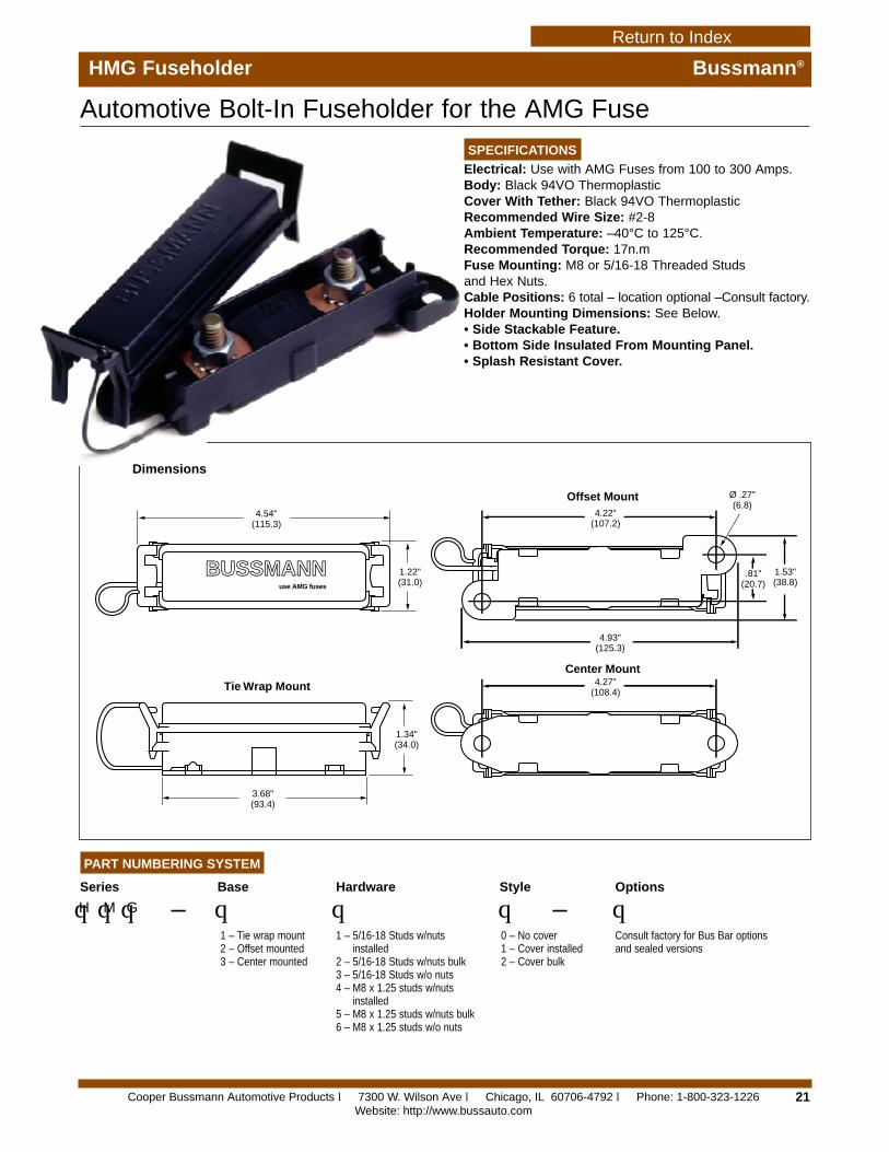
HMG Fuseholder Bussmann®
Automotive Bolt-In Fuseholder for the AMG Fuse
PART NUMBERING SYSTEM
Series
qqq –H M G
Base
q1 – Tie wrap mount2 – Offset mounted3 – Center mounted
Hardware
q1 – 5/16-18 Studs w/nuts
installed2 – 5/16-18 Studs w/nuts bulk3 – 5/16-18 Studs w/o nuts4 – M8 x 1.25 studs w/nuts
installed5 – M8 x 1.25 studs w/nuts bulk6 – M8 x 1.25 studs w/o nuts
Style
q –0 – No cover1 – Cover installed2 – Cover bulk
Options
qConsult factory for Bus Bar optionsand sealed versions
BUSSMANNuse AMG fuses
4.54"(115.3)
3.68"(93.4)
1.22"(31.0)
4.93"(125.3)
4.22"(107.2)
1.53"(38.8)
.81"(20.7)
1.34"(34.0)
4.27"(108.4)
Ø .27"(6.8)
Tie Wrap Mount
Center Mount
Offset Mount
Dimensions
SPECIFICATIONS
Electrical: Use with AMG Fuses from 100 to 300 Amps.Body: Black 94VO ThermoplasticCover With Tether: Black 94VO ThermoplasticRecommended Wire Size: #2-8Ambient Temperature: –40°C to 125°C.Recommended Torque: 17n.mFuse Mounting: M8 or 5/16-18 Threaded Studs and Hex Nuts.Cable Positions: 6 total – location optional –Consult factory.Holder Mounting Dimensions: See Below.• Side Stackable Feature.• Bottom Side Insulated From Mounting Panel.• Splash Resistant Cover.
Cooper Bussmann Automotive Products l 7300 W. Wilson Ave l Chicago, IL 60706-4792 l Phone: 1-800-323-1226Website: http://www.bussauto.com
Return to Index
22
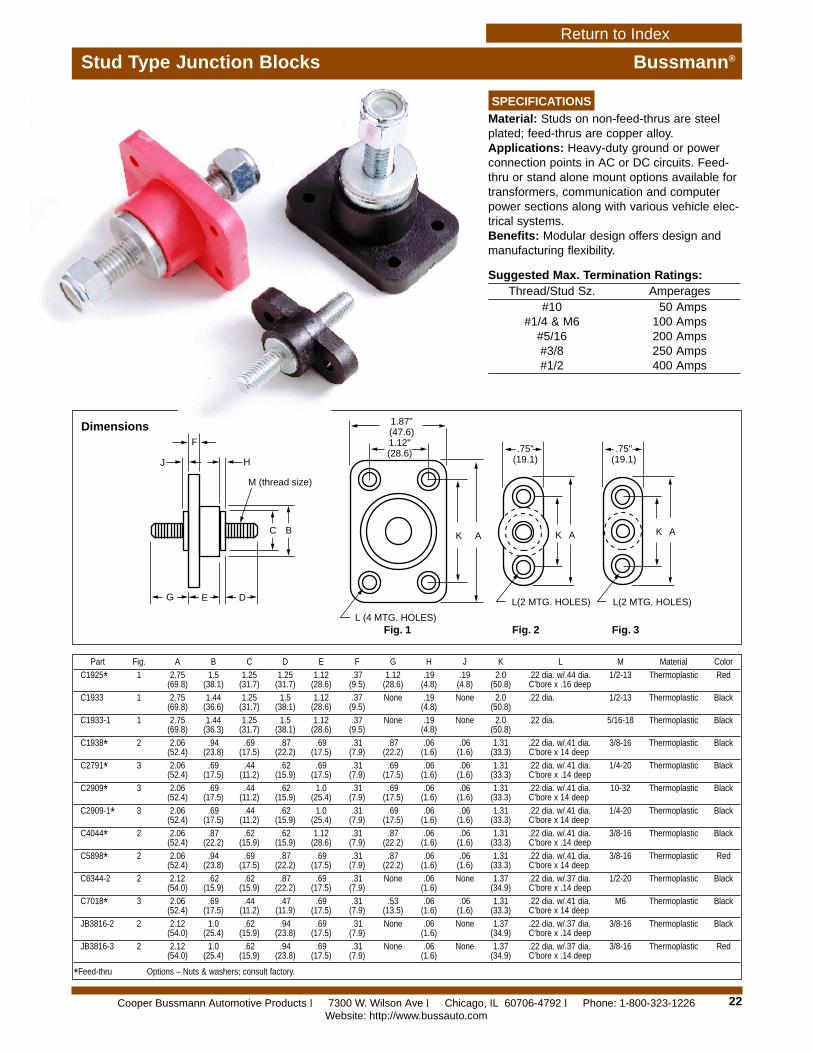
Stud Type Junction Blocks Bussmann®
SPECIFICATIONS
Material: Studs on non-feed-thrus are steelplated; feed-thrus are copper alloy.Applications: Heavy-duty ground or powerconnection points in AC or DC circuits. Feed-thru or stand alone mount options available fortransformers, communication and computerpower sections along with various vehicle elec-trical systems.Benefits: Modular design offers design andmanufacturing flexibility.
Suggested Max. Termination Ratings:Thread/Stud Sz. Amperages
#10 50 Amps#1/4 & M6 100 Amps
#5/16 200 Amps#3/8 250 Amps#1/2 400 Amps
Part Fig. A B C D E F G H J K L M Material Color
C1925* 1 2.75 1.5 1.25 1.25 1.12 .37 1.12 .19 .19 2.0 .22 dia. w/.44 dia. 1/2-13 Thermoplastic Red(69.8) (38.1) (31.7) (31.7) (28.6) (9.5) (28.6) (4.8) (4.8) (50.8) C’bore x .16 deep
C1933 1 2.75 1.44 1.25 1.5 1.12 .37 None .19 None 2.0 .22 dia. 1/2-13 Thermoplastic Black(69.8) (36.6) (31.7) (38.1) (28.6) (9.5) (4.8) (50.8)
C1933-1 1 2.75 1.44 1.25 1.5 1.12 .37 None .19 None 2.0 .22 dia. 5/16-18 Thermoplastic Black(69.8) (36.3) (31.7) (38.1) (28.6) (9.5) (4.8) (50.8)
C1938* 2 2.06 .94 .69 .87 .69 .31 .87 .06 .06 1.31 .22 dia. w/.41 dia. 3/8-16 Thermoplastic Black(52.4) (23.8) (17.5) (22.2) (17.5) (7.9) (22.2) (1.6) (1.6) (33.3) C’bore x 14 deep
C2791* 3 2.06 .69 .44 .62 .69 .31 .69 .06 .06 1.31 .22 dia. w/.41 dia. 1/4-20 Thermoplastic Black(52.4) (17.5) (11.2) (15.9) (17.5) (7.9) (17.5) (1.6) (1.6) (33.3) C’bore x .14 deep
C2909* 3 2.06 .69 .44 .62 1.0 .31 .69 .06 .06 1.31 .22 dia. w/.41 dia. 10-32 Thermoplastic Black(52.4) (17.5) (11.2) (15.9) (25.4) (7.9) (17.5) (1.6) (1.6) (33.3) C’bore x 14 deep
C2909-1* 3 2.06 .69 .44 .62 1.0 .31 .69 .06 .06 1.31 .22 dia. w/.41 dia. 1/4-20 Thermoplastic Black(52.4) (17.5) (11.2) (15.9) (25.4) (7.9) (17.5) (1.6) (1.6) (33.3) C’bore x 14 deep
C4044* 2 2.06 .87 .62 .62 1.12 .31 .87 .06 .06 1.31 .22 dia. w/.41 dia. 3/8-16 Thermoplastic Black(52.4) (22.2) (15.9) (15.9) (28.6) (7.9) (22.2) (1.6) (1.6) (33.3) C’bore x .14 deep
C5898* 2 2.06 .94 .69 .87 .69 .31 .87 .06 .06 1.31 .22 dia. w/.41 dia. 3/8-16 Thermoplastic Red(52.4) (23.8) (17.5) (22.2) (17.5) (7.9) (22.2) (1.6) (1.6) (33.3) C’bore x 14 deep
C6344-2 2 2.12 .62 .62 .87 .69 .31 None .06 None 1.37 .22 dia. w/.37 dia. 1/2-20 Thermoplastic Black(54.0) (15.9) (15.9) (22.2) (17.5) (7.9) (1.6) (34.9) C’bore x .14 deep
C7018* 3 2.06 .69 .44 .47 .69 .31 .53 .06 .06 1.31 .22 dia. w/.41 dia. M6 Thermoplastic Black(52.4) (17.5) (11.2) (11.9) (17.5) (7.9) (13.5) (1.6) (1.6) (33.3) C’bore x 14 deep
JB3816-2 2 2.12 1.0 .62 .94 .69 .31 None .06 None 1.37 .22 dia. w/.37 dia. 3/8-16 Thermoplastic Black(54.0) (25.4) (15.9) (23.8) (17.5) (7.9) (1.6) (34.9) C’bore x .14 deep
JB3816-3 2 2.12 1.0 .62 .94 .69 .31 None .06 None 1.37 .22 dia. w/.37 dia. 3/8-16 Thermoplastic Red(54.0) (25.4) (15.9) (23.8) (17.5) (7.9) (1.6) (34.9) C’bore x .14 deep
*Feed-thru Options – Nuts & washers; consult factory.
F
K A K A K A
J H
G E D
C B
M (thread size)
.75"(19.1)
.75"(19.1)
1.87"(47.6)1.12"(28.6)
L (4 MTG. HOLES)
L(2 MTG. HOLES) L(2 MTG. HOLES)
Fig. 1 Fig. 2 Fig. 3
Dimensions
Cooper Bussmann Automotive Products l 7300 W. Wilson Ave l Chicago, IL 60706-4792 l Phone: 1-800-323-1226Website: http://www.bussauto.com
Return to Index
23
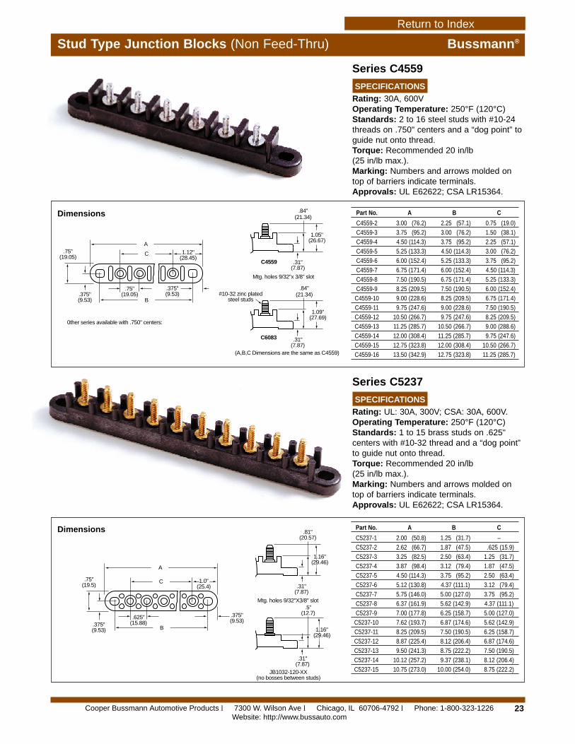
Stud Type Junction Blocks (Non Feed-Thru) Bussmann®
Series C4559
SPECIFICATIONS
Rating: 30A, 600VOperating Temperature: 250°F (120°C)Standards: 2 to 16 steel studs with #10-24threads on .750" centers and a “dog point” toguide nut onto thread.Torque: Recommended 20 in/lb (25 in/lb max.).Marking: Numbers and arrows molded ontop of barriers indicate terminals.Approvals: UL E62622; CSA LR15364.
Series C5237
SPECIFICATIONS
Rating: UL: 30A, 300V; CSA: 30A, 600V.Operating Temperature: 250°F (120°C)Standards: 1 to 15 brass studs on .625"centers with #10-32 thread and a “dog point”to guide nut onto thread.Torque: Recommended 20 in/lb (25 in/lb max.).Marking: Numbers and arrows molded ontop of barriers indicate terminals.Approvals: UL E62622; CSA LR15364.
A
C
B
.75"(19.5)
.375"(9.53)
.375"(9.53)
.625"(15.88)
1.0"(25.4) .31"
(7.87)
.31"(7.87)
.81"(20.57)
1.16"(29.46)
.5"(12.7)
Mtg. holes 9/32"X3/8" slot
JB1032-120-XX(no bosses between studs)
1.16"(29.46)
A
C
B
.75"(19.05)
.75"(19.05).375"
(9.53)
.375"(9.53)
1.12"(28.45)
0ther series available with .750" centers:
#10-32 zinc platedsteel studs
.31"(7.87)
.31"(7.87)
.84"(21.34)
.84"(21.34)
1.09"(27.69)
C6083
C4559
1.05"(26.67)
Mtg. holes 9/32"x 3/8" slot
(A,B,C Dimensions are the same as C4559)
Part No. A B C
C4559-2 3.00 (76.2) 2.25 (57.1) 0.75 (19.0)
C4559-3 3.75 (95.2) 3.00 (76.2) 1.50 (38.1)
C4559-4 4.50 (114.3) 3.75 (95.2) 2.25 (57.1)
C4559-5 5.25 (133.3) 4.50 (114.3) 3.00 (76.2)
C4559-6 6.00 (152.4) 5.25 (133.3) 3.75 (95.2)
C4559-7 6.75 (171.4) 6.00 (152.4) 4.50 (114.3)
C4559-8 7.50 (190.5) 6.75 (171.4) 5.25 (133.3)
C4559-9 8.25 (209.5) 7.50 (190.5) 6.00 (152.4)
C4559-10 9.00 (228.6) 8.25 (209.5) 6.75 (171.4)
C4559-11 9.75 (247.6) 9.00 (228.6) 7.50 (190.5)
C4559-12 10.50 (266.7) 9.75 (247.6) 8.25 (209.5)
C4559-13 11.25 (285.7) 10.50 (266.7) 9.00 (288.6)
C4559-14 12.00 (308.4) 11.25 (285.7) 9.75 (247.6)
C4559-15 12.75 (323.8) 12.00 (308.4) 10.50 (266.7)
C4559-16 13.50 (342.9) 12.75 (323.8) 11.25 (285.7)
Part No. A B C
C5237-1 2.00 (50.8) 1.25 (31.7) –
C5237-2 2.62 (66.7) 1.87 (47.5) .625 (15.9)
C5237-3 3.25 (82.5) 2.50 (63.4) 1.25 (31.7)
C5237-4 3.87 (98.4) 3.12 (79.4) 1.87 (47.5)
C5237-5 4.50 (114.3) 3.75 (95.2) 2.50 (63.4)
C5237-6 5.12 (130.8) 4.37 (111.1) 3.12 (79.4)
C5237-7 5.75 (146.0) 5.00 (127.0) 3.75 (95.2)
C5237-8 6.37 (161.9) 5.62 (142.9) 4.37 (111.1)
C5237-9 7.00 (177.8) 6.25 (158.7) 5.00 (127.0)
C5237-10 7.62 (193.7) 6.87 (174.6) 5.62 (142.9)
C5237-11 8.25 (209.5) 7.50 (190.5) 6.25 (158.7)
C5237-12 8.87 (225.4) 8.12 (206.4) 6.87 (174.6)
C5237-13 9.50 (241.3) 8.75 (222.2) 7.50 (190.5)
C5237-14 10.12 (257.2) 9.37 (238.1) 8.12 (206.4)
C5237-15 10.75 (273.0) 10.00 (254.0) 8.75 (222.2)
Dimensions
Dimensions
Cooper Bussmann Automotive Products l 7300 W. Wilson Ave l Chicago, IL 60706-4792 l Phone: 1-800-323-1226Website: http://www.bussauto.com
Return to Index
24
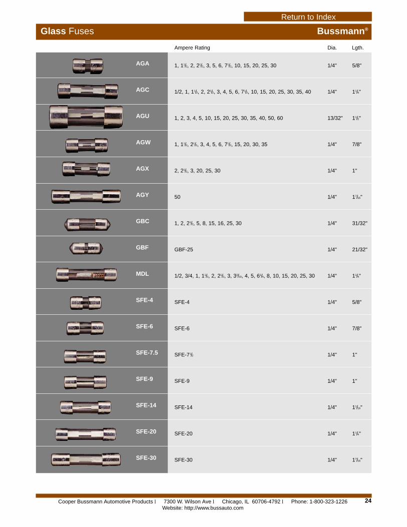
Glass Fuses Bussmann®
Ampere Rating Dia. Lgth.
AGA
AGC
AGU
AGW
AGX
AGY
GBC
GBF
MDL
SFE-4
SFE-6
SFE-7.5
SFE-9
SFE-14
SFE-20
SFE-30
1, 11/2, 2, 21/2, 3, 5, 6, 71/2, 10, 15, 20, 25, 30 1/4" 5/8"
1/2, 1, 11/2, 2, 21/2, 3, 4, 5, 6, 71/2, 10, 15, 20, 25, 30, 35, 40 1/4" 11/4"
1, 2, 3, 4, 5, 10, 15, 20, 25, 30, 35, 40, 50, 60 13/32" 11/2"
1, 11/2, 21/2, 3, 4, 5, 6, 71/2, 15, 20, 30, 35 1/4" 7/8"
2, 21/2, 3, 20, 25, 30 1/4" 1"
50 1/4" 17/16"
1, 2, 21/2, 5, 8, 15, 16, 25, 30 1/4" 31/32"
GBF-25 1/4" 21/32"
1/2, 3/4, 1, 11/2, 2, 21/2, 3, 32/10, 4, 5, 61/4, 8, 10, 15, 20, 25, 30 1/4" 11/4"
SFE-4 1/4" 5/8"
SFE-6 1/4" 7/8"
SFE-71/2 1/4" 1"
SFE-9 1/4" 1"
SFE-14 1/4" 11/16"
SFE-20 1/4" 11/4"
SFE-30 1/4" 17/16"
Cooper Bussmann Automotive Products l 7300 W. Wilson Ave l Chicago, IL 60706-4792 l Phone: 1-800-323-1226Website: http://www.bussauto.com
Return to Index
25
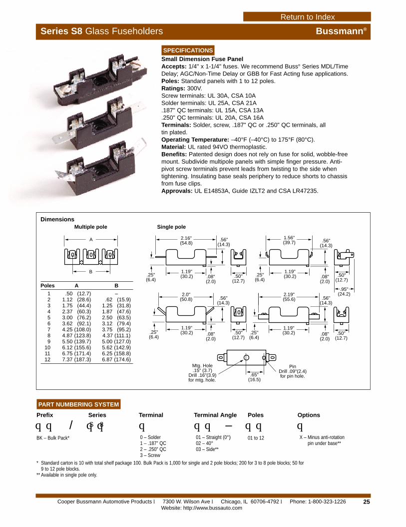
Series S8 Glass Fuseholders Bussmann®
SPECIFICATIONS
Small Dimension Fuse PanelAccepts: 1/4" x 1-1/4" fuses. We recommend Buss® Series MDL/TimeDelay; AGC/Non-Time Delay or GBB for Fast Acting fuse applications.Poles: Standard panels with 1 to 12 poles.Ratings: 300V.Screw terminals: UL 30A, CSA 10ASolder terminals: UL 25A, CSA 21A.187" QC terminals: UL 15A, CSA 13A.250" QC terminals: UL 20A, CSA 16ATerminals: Solder, screw, .187" QC or .250" QC terminals, all tin plated.Operating Temperature: –40°F (–40°C) to 175°F (80°C).Material: UL rated 94VO thermoplastic.Benefits: Patented design does not rely on fuse for solid, wobble-freemount. Subdivide multipole panels with simple finger pressure. Anti-pivot screw terminals prevent leads from twisting to the side whentightening. Insulating base seals periphery to reduce shorts to chassisfrom fuse clips.Approvals: UL E14853A, Guide IZLT2 and CSA LR47235.
A
B
2.16"(54.8)
1.19"(30.2)
1.19"(30.2)
.25"(6.4)
.25"(6.4)
.25"(6.4)
.08"(2.0)
.56"(14.3)
.08"(2.0)
.56"(14.3)
.08"(2.0)
.50"(12.7)
.50"(12.7)
.50"(12.7)
.50"(12.7)
2.0"(50.8)
2.19"(55.6)
1.19"(30.2)
.56"(14.3)
.56"(14.3)
.08"(2.0)
.25"(6.4)
.95"(24.2)
1.19"(30.2)
1.56"(39.7)
.65"(16.5)
Mtg. Hole.15" (3.7)
Drill .16"(3.9)for mtg. hole.
PinDrill .09"(2.4)for pin hole.
Multiple pole Single pole
PART NUMBERING SYSTEM
Prefix
qq /BK – Bulk Pack*
Series
qqS 8
Terminal
q0 – Solder1 – .187" QC2 – .250" QC3 – Screw
Terminal Angle
qq –01 – Straight (0°)02 – 40°03 – Side**
Poles
qq01 to 12
Options
qX – Minus anti-rotation
pin under base**
* Standard carton is 10 with total shelf package 100. Bulk Pack is 1,000 for single and 2 pole blocks; 200 for 3 to 8 pole blocks; 50 for 9 to 12 pole blocks.
** Available in single pole only.
Poles A B
1 .50 (12.7) –2 1.12 (28.6) .62 (15.9)3 1.75 (44.4) 1.25 (31.8)4 2.37 (60.3) 1.87 (47.6)5 3.00 (76.2) 2.50 (63.5)6 3.62 (92.1) 3.12 (79.4)7 4.25 (108.0) 3.75 (95.2)8 4.87 (123.8) 4.37 (111.1)9 5.50 (139.7) 5.00 (127.0)
10 6.12 (155.6) 5.62 (142.9)11 6.75 (171.4) 6.25 (158.8)12 7.37 (187.3) 6.87 (174.6)
Dimensions
Cooper Bussmann Automotive Products l 7300 W. Wilson Ave l Chicago, IL 60706-4792 l Phone: 1-800-323-1226Website: http://www.bussauto.com
Return to Index
26
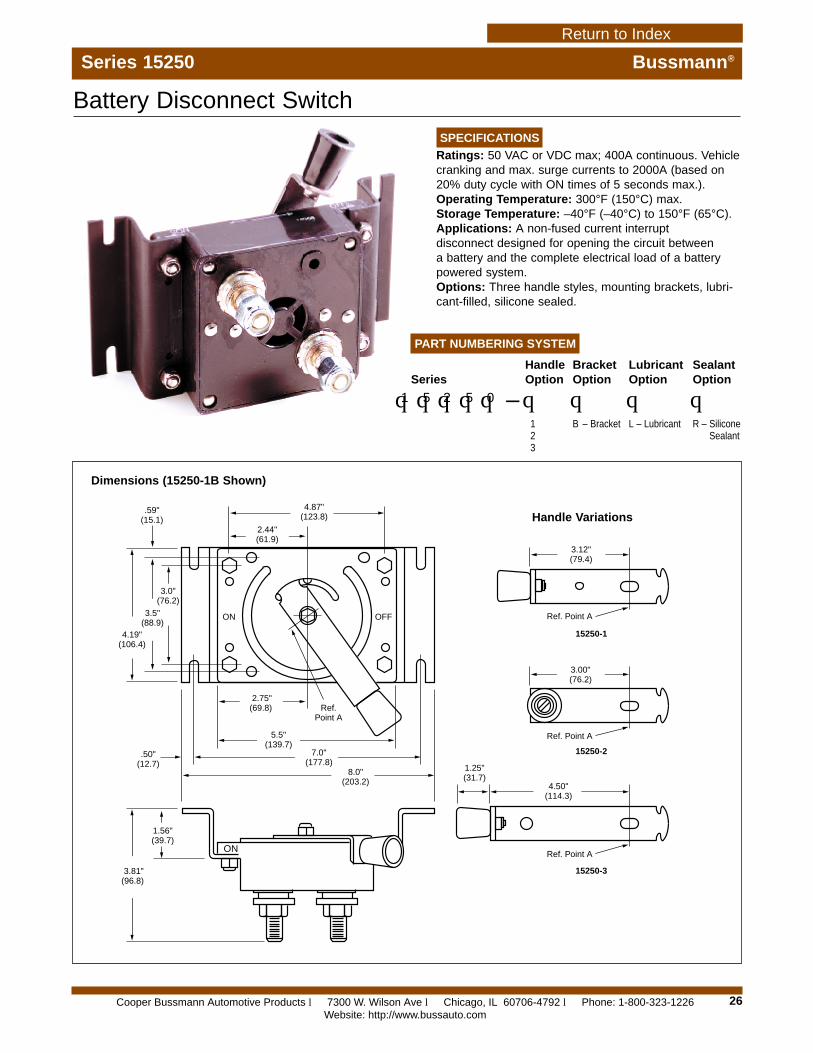
Series 15250 Bussmann®
SPECIFICATIONS
Ratings: 50 VAC or VDC max; 400A continuous. Vehiclecranking and max. surge currents to 2000A (based on20% duty cycle with ON times of 5 seconds max.).Operating Temperature: 300°F (150°C) max.Storage Temperature: –40°F (–40°C) to 150°F (65°C).Applications: A non-fused current interrupt disconnect designed for opening the circuit between a battery and the complete electrical load of a batterypowered system.Options: Three handle styles, mounting brackets, lubri-cant-filled, silicone sealed.
Battery Disconnect Switch
ON
ON
OFF
3.81"(96.8)
1.56"(39.7)
.50"(12.7)
2.75"(69.8) Ref.
Point A
5.5"(139.7)
7.0"(177.8)
8.0"(203.2)
4.19"(106.4)
3.5"(88.9)
3.0"(76.2)
.59"(15.1)
4.87"(123.8)
2.44"(61.9)
1.25"(31.7)
3.12"(79.4)
Ref. Point A
Ref. Point A
Ref. Point A
3.00"(76.2)
4.50"(114.3)
15250-1
15250-2
15250-3
Dimensions (15250-1B Shown)
Handle Variations
PART NUMBERING SYSTEM
Series
qqqqq –1 5 2 5 0
BracketOption
qB – Bracket
LubricantOption
qL – Lubricant
SealantOption
qR – Silicone
Sealant
HandleOption
q123
Cooper Bussmann Automotive Products l 7300 W. Wilson Ave l Chicago, IL 60706-4792 l Phone: 1-800-323-1226Website: http://www.bussauto.com
Return to Index
27
Cross Reference Bussmann®
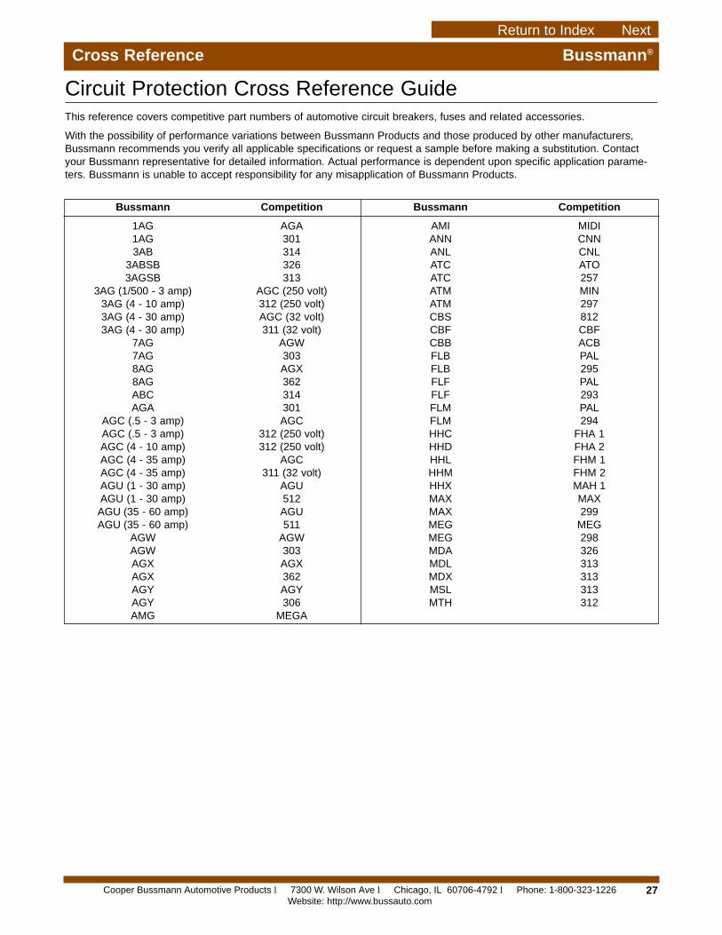
This reference covers competitive part numbers of automotive circuit breakers, fuses and related accessories.
With the possibility of performance variations between Bussmann Products and those produced by other manufacturers,Bussmann recommends you verify all applicable specifications or request a sample before making a substitution. Contactyour Bussmann representative for detailed information. Actual performance is dependent upon specific application parame-ters. Bussmann is unable to accept responsibility for any misapplication of Bussmann Products.
Circuit Protection Cross Reference Guide
1AG AGA1AG 3013AB 314
3ABSB 3263AGSB 313
3AG (1/500 - 3 amp) AGC (250 volt)3AG (4 - 10 amp) 312 (250 volt)3AG (4 - 30 amp) AGC (32 volt)3AG (4 - 30 amp) 311 (32 volt)
7AG AGW7AG 3038AG AGX8AG 362ABC 314AGA 301
AGC (.5 - 3 amp) AGCAGC (.5 - 3 amp) 312 (250 volt)AGC (4 - 10 amp) 312 (250 volt)AGC (4 - 35 amp) AGCAGC (4 - 35 amp) 311 (32 volt)AGU (1 - 30 amp) AGUAGU (1 - 30 amp) 512AGU (35 - 60 amp) AGUAGU (35 - 60 amp) 511
AGW AGWAGW 303AGX AGXAGX 362AGY AGYAGY 306AMG MEGA
AMI MIDIANN CNNANL CNLATC ATOATC 257ATM MINATM 297CBS 812CBF CBFCBB ACBFLB PALFLB 295FLF PALFLF 293FLM PALFLM 294HHC FHA 1HHD FHA 2HHL FHM 1HHM FHM 2HHX MAH 1MAX MAXMAX 299MEG MEGMEG 298MDA 326MDL 313MDX 313MSL 313MTH 312
Bussmann Competition Bussmann Competition
Cooper Bussmann Automotive Products l 7300 W. Wilson Ave l Chicago, IL 60706-4792 l Phone: 1-800-323-1226Website: http://www.bussauto.com
Return to Index Next
28
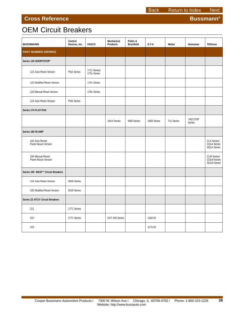
Cross Reference Bussmann®
OEM Circuit BreakersControl Mechanical Potter &
BUSSMANN Devices, Inc. FASCO Products Brumfield E-T-A Weber Heineman TI/Klixon
PART NUMBER (SERIES)
Series 120 SHORTSTOP®
121 Auto Reset Version PSA Series1711 Series/1731 Series
122 Modified Reset Version 1741 Series
123 Manual Reset Version 1781 Series
124 Auto Reset Version PSA Series
Series 174 FLAT-PAK
16XX Series W58 Series 1658 Series T11 Series“HECTOR”Series
Series 180 HI-AMP
181 Auto Reset/ CLA Series/Panel Mount Version CDLA Series
SDLA Series
184 Manual Reset/ CLM Series/Panel Mount Version CDLM Series
SDLM Series
Series 190 MAXI™ Circuit Breakers
191 Auto Reset Version 9000 Series
192 Modified Reset Version 9100 Series
Series 22 ATC® Circuit Breakers
221 1771 Series
222 2771 Series EXT 200 Series 1160-02
223 1170-02
Cooper Bussmann Automotive Products l 7300 W. Wilson Ave l Chicago, IL 60706-4792 l Phone: 1-800-323-1226Website: http://www.bussauto.com
Return to IndexBack Next
Cooper BussmannAutomotive Products7300 W. Wilson Ave.Chicago, IL 60706-4792Telephone: 800-323-1226Facsimile: 708-867-2211
Cooper BussmannP. O. Box 14460St. Louis, Missouri 63178-4460Telephone: 636-394-2877Facsimile: 800-544-2570
European HeadquartersCooper Bussmann U.K. Ltd.Burton-on-the-WoldsLeicestershire LE12 5 TH EnglandTelephone: 44-1509-882737Facsimile: 44-1509-882786
Cooper Bussmann Denmark5 LiterbuenDK-2740 SkovlundeCopenhagen, DenmarkTelephone: 45-4485-0900Facsimile: 45-4485-0901
Cooper Bussmann Automotive ProductsSales Office - GermanyGoldregenweg 285551 KirchheimTelephone: 49-89-904-80946Facsimile: 49-89-903-3086
Cooper Bussmann Asia Pacific1 Jalan Kilang Timor#06-01 Pacific Tech CentreSingapore 159303Telephone: 65-278-6151Facsimile: 65-278-3151
Cooper Bussmann AustraliaBlock X, 391 Park RoadP.O. Box 257Regents Park, SydneyNSW 2143, AustraliaTelephone: 61-2-9743-8333Facsimile: 61-2-9743-8070
Cooper Bussmann India2nd Floor, Unit #5, White House23-29, St. Marks RoadBangalore - 560 001, IndiaTelephone: 91-80-227-0893Facsimile: 91-80-224-5725
Cooper Bussmann BrazilRodovia Santos Dumont, Km 23Cruz das Almas - 13.300-000Caixa Postal 095Itu-Sao Paulo BrazilTelephone: 55-11-7824-1856Facsimile: 55-11-7824-1721
Cooper Bussmann MexicoArrow-Hart, S.A. de C.V.Poniente 148, No. 93302300 Mexico, D.F. MexicoTelephone: 525-587-0211Facsimile: 525-567-4049
Bussmann®
Worldwide Circuit Protection Solutions
FORM NO. ABC/10M/1199
Automotive Products
Bussmann
Cooper Bussmann Automotive Products l 7300 W. Wilson Ave l Chicago, IL 60706-4792 l Phone: 1-800-323-1226Website: http://www.bussauto.com
Return to IndexBack