bussmann division - hagelec co electronic and electrical ...hagelec.com/asl.pdf · low voltage fuse...
TRANSCRIPT

AUTOMATIC SECTIONALISING LINK
For Overhead Line ProtectionCIRCUIT PROTECTION SOLUTIONS
Your Representative
NH FUSE SYSTEM LOW VOLTAGE FUSE LINKS
EXPLUSION FUSE LINKS IEC CYLINDRICAL FUSE SYSTEM
HIGH SPEED FUSES HIGH VOLTAGE PRODUCTS
NH FUSE SYSTEM
EXPLUS I ON FUSE L INKS
LOW VOLTAGE FUSE L INKS
I EC CYL INDR I CAL FUSE SYSTEM
H IGH SPEED FUSES H IGH VOLTAGE PRODUCTS
Bussmann DivisionCooper (UK)
Burton-on-the-Wolds · Leicestershire · LE12 5TH UK
Telephone: 44 (0)1509 882 737
Facsimile : 44 (0)1509 882 786
http://www.bussmann.co.uk
Bussmann manufacture a wide range of
products for the protection of electrical and
electronic circuits.....Fuse Links, Fuse Holders,
and Fusegear, all readily available from
manufacturing sites in the United Kingdom,
Denmark, United States, Brazil and Mexico.
Bussmann is a division of Cooper Industries
Inc., a diversified world-wide manufacturer of
electrical products, tools and power equipment.
Bussmann has grown through both organic
growth and acquisition. Acquisitions have
included the fusegear division of Lauritz
Knudson (LK-NES), Beswick which added UK
Domestic fuses as well as IEC and UL
Electronic fuses, Hawker Fusegear (formerly
Brush Fusegear Ltd) which strengthened our
range of power fuses and Fusegear.
Bussmann circuit protection solutions comply
with major international standards: BS, IEC,
UL, CSA... manufacturing operations have
earned ISO 9000 certification, ensuring the
utmost quality across every product.
IASL CSP - 03

Cooper Bussmann are one of the world’s leading suppliers of fuses and
fusible protection systems. Provider of the world’s first truly global product
line, each product is backed by an efficient world-wide distribution network
service and unrivalled technical support. Cooper Bussmann circuit protection
solutions comply with major international standards: BS, IEC, DIN and UL.
Cooper Bussmann High Voltage fuses have absorbed and embodied the expertise and
experience of thirteen of the most prestigious manufacturers and are able to offer an
unbeatable range of products in terms of technical excellence, performance and quality.
Cooper Bussmann offer a wider range of High Voltage fuses than any other
manufacturer and types are available to meet most service applications. With over
50 years’ experience in design and manufacture, Cooper Bussmann have supplied
fuselinks to more than 90 countries world-wide.
Cooper Bussmann High Voltage fuses are extremely effective in preventing damage
to a system in the event of a fault, due to considerable limitation of let-through
current in DIN and British Standard designs to the latest IEC requirements.
Cooper Bussmann are pioneers in the development of Full Range High Voltage
fuselinks and is consequently the market leader in this field offering genuine full range
characteristics.
Cooper Bussmann’s team of specialist engineers play a leading role in international
standardisation of High Voltage fuses, offering a comprehensive service of advice,
on selection and applications.
With a continual commitment to meet our customers’ needs, with innovative, high
quality products with ISO 9002 ‘approved systems’, Cooper Bussmann are the
suppliers choice for High Voltage Circuit Protection Solutions.
WORLD-WIDE CIRCUIT PROTECTION SOLUTIONS This booklet provides detailed information on the Cooper Bussmann InterchangeableAutomatic Sectionalising Link (ASL) or Smart Link for use in distribution cut-outs.
ASL CONTENTS/INFORMATION
Low cost retrofit option for spur line isolation in place of existing expulsion fuses
Available for up to 38kV overhead lines.
Pick-up current ratings from 15 to 320 Amps.
Enhanced lightning immunity perfomance.
1, 2 or 3 shot options available.
Electronic circuit fully encapsulated.
The Bussmann Automatic Sectionalising
Link (ASL), represents a significant
breakthrough in the field of medium voltage
overhead line distribution system protection,
offering considerable savings in operating
costs and minimising unnecessary
interuptions to customers.
Using the Bussmann ASL, an economical
system can be installed utilising most
existing explusion drop out fuse mounts
in conjunction with multishot circuit
breakers or auto-reclosers. Even where
no expulsion fuse mounts exist and these
have to be provided, significant benefits
can still be achieved.
Major benefits in efficiency and performancesare achieved by:
• Reducing outages caused by transient no-damage faults, especially due to lightning, whichwould otherwise cause unneccessary operationof expulsion fuse-links.
• Reducing unnecessary ‘call outs’ due to nuisancetransient faults.
• Sectionalising and isolating the network therebyreducing the number of customers disconnecteddue to permanent faults.
• Providing visual identification of a fault downstreamof the ASL and therefore allowing speedy
restoration of supply.
Statistics show that up to 90% of expulsion fuse-link operations on spur lines are in response totransient no-damage faults. The cost for eachexpulsiton fuse-link replacement can be the sameas the capital cost of a complete fuse cut-out.Thealternative approach of replacing expulsion fuse-links by solid links has the disadvantage that anypermanent fault on a spur line results in an outageof the whole system.
The Bussmann ASL ensures effective overheadspur line isolation in the event of a genuine localfault, while at the same time remaining unresponsiveto transient (temporary) no-damage surge currents.
INTRODUCTION>

a
Cut away diagram shows a BR1 type ASL
Cut away diagram of the Sectionaliser CONSTRUCTIONAL DETAILS
FIGURE 1
21
1. Increased network reliability with an overall reduction in cost
The ASL discriminates between transient and permanent faults only giving automatic disconnectionof permanent faults. By virtually eliminating nuisanceoutages, significant reduction in system running costsare achieved.
2. Comprehensive range of ratings
ASL’s are available with voltage ratings up to 38kVpick-up currents from 15 to 320A and 1, 2 or 3count options.Colour bands are provided for easyidentification of count and pick up rating.
3. Fits into existing expulsion fuse mounts
ASL’s are available to fit most expulsion fuse mounts.‘BR’ types fit most UK mounts. C-type version fits all the common NEMA interchangeable mounts suchas S & C, Chance, ABB etc, ASL’s are installed &removed using existing pole head equipment.
4. Silent, reliable drop-out action
High output force of replacement chemical actuatorprovides rapid reliable drop out action, even undericing to provide visual indication of a faulty line. Deadtime operation ensures no sparks, ionised gas orcontact erosion, minimising fire risks.
FEATURES
CONSTRUCTION
The Bussmann ASL is designed for use in expulsion fusemounts by replacing the fuse-link and carrier tube. Avariety of ASL’s are available to fit most fuse mountsincluding the single vent interchangeable type for use inNEMA type distribution cut outs.
The ASL houses a fully encapsulated logic circuit withinits main conductive tube powered by encapsulated smallcurrent transformers mounted on the outside of thetube. This ensures that the electronic circuitry is freefrom electrical interference as the tube acts as an effectiveFaraday cage. The logic circuit is also environmentallyprotected to prevent moisture ingress. Energy derivedfrom the current transformers under fault conditionsallows the ASL to be self powered to ensure operationeven when there is no initial load current.
In appearance the upper and lower contacts of the ASLresemble that of the fuse carrier it replaces. Instead ofa fuse element melting to release the carrier from themount, operation is accomplished by discharging acapacitor into a small chemical actuator (or ‘striker’)which unlatches the carrier tube and causes it to swingdown in the manner of an expulsion fuse carrier.
The chemical actuator is an extremely reliable devicewith high mechanical advantage, which by means of asmall electrical current convert’s chemical energy intomechanical movement, providing rapid, reliable drop outaction even under icing conditions. The actuator iscompletely safe to handle and there are no-special storageor transporting requirements.
The ASL is reset by fitting a replacement actuator andre-inserting the carrier into it’s mount. The resettingoperation will normally take less time than that neededto change a blown expulsion fuse- link.
5. Immunity to magnestising inrush current
The logic circuit is programmed to ignore first halfcycle current end react only if both the negative andpositve half cycles exceed the pick-up current. Asmagnetising inrush currents are largely undirectionalthey are ignored by the logic circuit.
6. Surge and EMI protection
Electronics are shielded from magnetic field influencesby being enclosed within the conducting tube. TheASL is tested to withstand lightning impulse currentsand to be immune to radio frequency interference.
7. Self powered, no maintenance
Power required to drive the logic circuit and actuatoris supplied by two current transformers during thepassage of fault current. No additional power sourceis required or routine maintenance is needed.
8. Low threshold for hold off current (250 milliamps)
This ensures that a return to load current followinga temporary fault will not result in a mistaken countby the ASL.
>
>

ILLUSTRATION BELOW SHOWS A 2 SHOT DEVICE
LEVEL OF CURRENTIN THE MAIN LINE
FAULT CURRENT
NOMINAL LOAD CURRENT
AUTO RE-CLOSER CONTACTS
CLOSED CLOSED
FIRST PULSENOTED ANDSTORED IN SECTIONALISER'S MEMORY
OPERATIONAL SEQUENCE OF A SECTIONALISER ISOLATING A SPUR LINE FAULT
LATCHED POSITION DE - LATCHED POSITION
FIGURE 3
3 4
Under normal load conditions the electronics remaininert. However, should the line current increase abovea certain pre-set value (the pick-up current) the logiccircuit activates.
The upstream auto-recloser then opens, temporarilyremoving the fault from the line. The logic circuit poweredby an internal capacitor, stores the incident for around25 seconds (the ‘reclaim time’).
When the upstream device recloses, typically 3 to 10seconds later, if the fault current is no longer in evidence,the ASL will ignore the incident after the reclaim timeand eventually reverts to an inert state again. However,if the fault current (ie. current above the pick-up current)is still present, the logic circuit will decide that thisrepresents a permanent fault on the spur line and for atwo count unit will prepare to de-latch.
SECTIONALISER
FAULTTXTX
SPUR LINE
MAIN OVERHEAD LINE
AUTO RE-CLOSER
(Pole mounted Auto-re-closer or circuit breaker fittedwith Auto-recloserrelay protection)
FIGURE 2
OPERATION
The logic circuit is inhibited from operating the latchmechanism until the upstream recloser has tripped forthe second time and the line current has fallen to a valueof less than 250mA (the ‘hold-off’ current) for a periodof at least 0.1 second.
The ASL thus operates during the dead time of theupstream protective device and does so quickly, withoutsparks or ionised gas emission and without contact erosion.
The logic circuit is designed to inhibit response to transformermagnetising inrush current surges. Thus ASL’s on healthyspur lines are not spuriously operated by such currents,following repeated operations of the upstream recloser.
In practice, any spur-line fault conditions which persistsfor a time long enough to operate the upstream recloserwill operate the ASL, so isolating the spur as illustratedin fig 2. Any transient or ‘no-damage’ current will be ignored.
>

5 6
Historically in many countries using a low impedienceearthed 3-wire overhead line system the individualprotection of a spur line is provided by explusion typefuse-links which are intended to operate only during apersistent fault on the spur. In this group-fused systemone fuse controls a group of transformers in conjunctionwith either an upstream circuit breaker having amultishot facility or an auto-recloser.
However in practice it has been found that there is amuch higher proportion of fuse-link operations corresponding
Limitation of expulsion fuse-links and auto-reclose circuit breaker combination
APPLICATION
to ‘non-damage’ faults than damage faults. To reducenon-damage faults some utilities replaced all fuse-linksbeyond the auto-recloser with solid links and the auto-recloser set for instantaneous trips. The disadvantagesof this so called ‘solid system’ is the increased zone protectedby the reclosing device leading to a greater number ofconsumers effected by each fault on a spur line.
The availability of the ASL now achieves the discriminationfeature of providing individual spur protection withoutthe disadvantages of non-damage fault fuse-link operations.
The intended performance of expulsion fuse-links fittedat the major spurs and an upstream autorecloser (equippedwith one instantaneous and followed by at least onedelayed trip) is that for non-damaged faults on a fusedspur, the circuit breaker trips instantaneously and thefuse-link element remains intact. The auto-recloserrecloses after the dead time with the fault no longerpresent thus restoring supply to all customers.
For damage faults, the auto-recloser trips instantaneouslyand the fuse-link element remains intact. The auto-recloserrecloses after dead time but as the fault is still presentthe fuse-link operates before the delayed protection ofthe auto-recloser. When the auto-recloser closes for thethird time all customers have supply except those beyondthe fuse.
However in practice there exists a current where thefuse-link characteristic crosses the instantaneouscharacteristic of the auto-recloser. This leads to aproportion of fuse-links operating before or during thebreaker operation. If a fault is permanent nothing is lost,
but if a fault is of the non-damage type a non-damagefuse-link operation will occur. Such non-damage fuse-linkoperations are widely un-welcome and are most widelyassociated with lightning strikes, which can producethese high current transients.
In addition, for low earth fault currents, there will be azone where the expulsion fuse-link will not operate duringthe delayed protection of the auto-recloser resulting inlockout of the auto-recloser. This will lead to all customersdownsteam from the auto-recloser losing supply ratherthan just those on the faulty spur with a subsequentincrease in customer minutes lost.
Typically for a 30A type T expulsion fuse-link, the 10second melting time is 120A leaving a large zone of faultcurrents below this where lockout of the auto-recloserwill occur. Recent measurement studies have shown thatin the case of one UK utility 50% of earth faults wereless than 100 Amps. Conventional group fusing wouldhave resulted in recloser lockout for these faults, aswould operation of a ‘solid system’.
>
30T Fuse Curve
Delayed Over Current
Delayed Earth Fault
DMT Sensitive Earth Fault
Instantaneous Over Current
Instantaneous Earth Fault
Co-ordinationrange
5 101
102
103
104
10- 2
10- 3
10- 1
100
101
102
103
CURRENT
AUTO RE-CLOSER FUSE CO-ORDINATION
TIM
E

Delayed Over Current
Delayed Earth Fault
DMT Sensitive Earth Fault
Instantaneous Over Current
Instantaneous Earth Fault
Co-ordinationrange
5 101
102
103
104
10- 2
10- 3
10- 1
100
101
102
103
CURRENT
AUTO RE-CLOSER ASL CO-ORDINATES
TIM
E
78
Advantages of ASL and auto-reclosing circuit breaker combination
The main advantage of the ASL, is that discriminationwith pole mounted auto-recloser or ground mountedmultishot circuit breaker is assured down to the minimumoperating current of the ASL without the necessity fordelayed trips. Auto-reclosers can therefore be set forinstantaneous trip thus minimising system damage. Faultwithstand is not an issue as the short time-currentwithstand rating of the ASL will be greater than theavailable fault current except for a few possible applicationsnext to a substation.
In the case of low earth fault currents, by selecting anASL with minimum pick up current at or below theminimum trip current of the auto-recloser where possible,
these earth faults will result in operation of the ASL onthe faulty spur, thus preventing lockout of the recloserand wide loss of supply to customers.To achieve theoptimum level of co-ordination and to take account oftolerances, the lowest rating of ASL should be 80% ofthe earth fault or sensitive earth fault settings, dependenton the scheme employed.
The diagram below illustrates an enhanced protectionscheme utilising the full potential of the ASL’s. Anypermanent fault on the spurs fitted with the ASL’s thatcauses reclose operations of the PMAR will also causeoperation of the ASL in the faulted spur.
PMAR
63Amp3 count ASL
Spur Line
16A2 count ASL
Earth Fault
Pole mounted Auto re-closerLOWEST E/F or SEF 20A
Main overhead line
16A2 count ASL
16A2 count ASL
ENHANCED PROTECTION SCHEME USING AUTOMATIC SECTIONALISING LINKS
With a conservative estimate of £100 for the cost of a callout for a two men crew, application of an ASL on a spur locationcan be easily justified when more than two nuisance outages would otherwise occur over the expected life of the ASL.Assuming a 20 year life expectancy, an ASL is justified where there are more then 0.1 non damage fuse-link operationsper spur location per year. In practice, dependent on the loading on the spur, typically it has been found that an ASL iscost effective for spur lines longer than 1 to 3 Km. For spur lines longer than 4 to 6 Km further economic sectionalisingof the line will be achieved by putting 2 ASL’s in series. In this case the downstream ASL will have one less count than theupstream ASL as shown in fig. 4.
ASL
ASL
ASL
ASL
FIGURE 4

9 10
In the United States the most common type of overheadprimary distribution circuit is the four-wire multiearthed– neutral system. A typical distribution system will besimilar to that in fig? A main line (feeder) with a reclosernear its head originates from a substation with severalspurs (laterals) tapped off this feeder. Often further branchlines are tapped off the spur (lateral) which in turn supplypower to end users. Individual transformers are individuallyfused and also fuses at the head of branches and lateralsprovide further sectionalising of the system.
In general the individual transformer fuse-links are sizedso that it will operate on all selected overcurrents withoutcausing the recloser to operate. Operation of this fuse-link affects a small number of customers making suchoperations easily justifiable.
The fuse-link at the head of the lateral or branch co-ordinates with the recloser in the same way so describedfor the group fused system with some of the samelimitations. There is a maximum current beyond which
the fuse-link will operate before the recloser has a chanceto clear a temporary fault.Under high transient faultconditions, such as caused by lightning, nuisance fuse-linkblowing can result. As these circuits are characterised bycomparitively high earth fault currents fuse-links are usedeffectively for earth fault protection
Most of the distribution circuits have at least two expulsionfuse-links in series. Due to the non-current limiting natureof expulsion fuse-links there is a maximum current atwhich co-ordination can be achieved. Above this currentit is likely that both the upstream and downstreamexpulsion fuse-links will operate at the same time.
In both examples it is the common denominator of thefuse at the head of the lateral (spur) that gives rise tothe limitations in operational performance.
By replacing a fuse with an ASL at the head of a lateralor branch the co-ordination range is extended to themaximum short time withstand rating of the ASL.
North American Practice
TYPICAL NORTH AMERICAN DISTRIBUTION SYSTEM
PMAR
CutoutSpur Line
or lateral
Pole mounted Auto re-closer
Main overhead line or feeder
Transformer
Cutout
TYPICAL NORTH AMERICAN DISTRIBUTION SYSTEM USING AUTOMATIC SECTIONASING LINKS
PMAR
3 count ASL
Spur Line
or lateral
Pole mounted Auto re-closer
Main overhead line or feeder
Transformer
Cutout
2 count ASL
2 count ASL
2 count ASL
ASL
ASL
ASL
ASL

11 12
SELECTION
System Voltage
The ASL is insensitive to system voltage and being in effecta solid conductor has no insulation requirements. Hencethe sole criterion concerning voltage is that the ASL fitsinto a mount of the appropriate voltage rating, meetingthe dialectric values required (BIL & power frequency).
Pick-Up Current (Actuating Current)
For optimum co-ordination the lowest rating of ASL shouldbe 80% of the minimum earth fault or sensitive earthfault settings allowing auto-recloser operations.
However, depending on the position of the ASL it mustbe chosen to withstand the possible transformer magnetisinginrush currents.
When a recloser switches in and out attempting to cleara fault on one branch circuit, all the healthy circuitsexperience surge currents due to magnestising inrushdetermined by the transformer KVA.
The anti-magnetising inrush circuit in the ASL ensuresagainst spurious operation, provided both positive andnegative going half cycles, are below the pick up valve. Ifthe ratio of transformer capacity/pick up settings ismade too small, then even the smaller loops of the highlyasymmetrical magnetising in-rush current, maybe ofsufficient valve to override the inhibiting circuit and allowoperation to occur.
IEEE standard C37-63 for mainline sectionalisers allowsa ratio of 1.6:1 for total available transformer currentto pick up current.
Present experience suggests that this is satisfactory formost applications of 2 and 3 count ASL’s. For 1 shotASL’s and applications where the transformer KVA isdominated by one large transformer, ie. more than 60%of the total, a ration of 2.5:1 is recommended.
For example: for 2 and 3 count ASL’s a 40A pick-upsetting allows for maximum installed transformer capacityof up to 25A. Even though the maximum loading on theline might be 5A, a small percentage of the maximumavailable, magnetising in-rush which is dependant on theinstalled KVA is the determining factor.
Frequency
The ASL must have a frequency rating equal to the supplyfrequency of either 50 or 60Hz.
No of Counts
The number of counts to operate is factory pre-set. TheASL should be chosen to operate in at least one less countthan the back up recloser. For example, a 4 shot recloserwould require a maximum of a 3 count ASL downstream.To reduce the number of recloser operations a 2 countunit would be the most common. Where ASL’s are usedin series the downstream ASL should be one less countthan the upstream ASL. 1 Count ASL’s are also available,for applications such as underground cables where transientfaults are unlikely. Choice of an ASL over a fuse eliminatesthe co-ordination issues discussed previously.
Maximum Fault Current
The ASL must have a short time-current withstand equalto or greater than the available fault current (seePerformance Characteristics).
Continuous Current
The ASL must have a continuous current rating equal toor greater than the anticipated system load current. Thisis normally not an issue as all ASL’s are rated at 200Acontinuous.
Reclaim Time
The reclaim time is the time that the memory of the ASLretains prior counts and is nominally 25 seconds. Howeverin practice this time will vary with the value and durationof fault current pulses. For high values of fault current,particularly where the upstream recloser is operating indelayed mode, the ASL reclaim time may extend by up to15% while for instantaneous tripping operation at lowervalues of current near the pick up value, reclaim timesmay be reduced by 15%. For these reasons it is recommendedthat the maximum reclose time (dead time between shots)of the recloser be 15 seconds, as this must be shorterthan the ASL reset time for correct co-ordiation.
When selecting an ASL for each installation a number of features have to be taken into account
>
Rated Maximum Voltage: 15kV (110kV BIL), 27kV (150kV BIL), 38kV (170kV BIL)
Maximum thermal rating: 200A
Rated Frequency: 50Hz, 60 Hz
Pick Up Current: 60Hz operation (+-10%) 16, 24, 40, 56, 80, 112, 160, 200, 320 Amps50Hz operation (+-15%) 15, 20, 25, 40, 50, 63, 80, 100, 200, 320 Amps
Number of counts: 1, 2 or 3
Hold off current: 250 milliamps
Current Withstand: Continuous 200A
Momentary 1st peak 16,000 Amps
1 sec 8000 Amps Symmetrical
10 sec 2600 Amps Symmetrical
Reclaim times: 25 seconds (+- 15%)
Response time:Minimum duration of current pulse 25 msec @ 1.5 X pick up settingfor overcurrent memory response: 60 msec @ 1.2 X pick up setting
Circuit breaker dead time range: 0.5 sec to 15 sec
Minimum time of dead line after fault pulse for count: 80 msec
Ambient temperature limits: -30CºC to 80ºC
Surge Current withstand: 65KA per ANSI C37, 63 IEEE 62.11 & IEC EN60099-1
Performance Characteristics
Dead Time
The time for an ASL to drop down to a safe isolatingdistance (from the instant when the line goes ‘dead’ afterthe correct number of counts) is approximately 250milliseconds. To obviate any possibility of the unit attemptingto open under live conditions the upstream reclosershould have a dead line time of not less than 0.5 seconds.
In the case of three phase ganged unit, the total timetaken for all three modules to drop down to a safe isolatingdistance is around 750 milliseconds. Hence the upstreamrecloser should not have a dead line time less than 1.5seconds to ensure against mal operation.
Over Voltage Protection
Over voltage protection is the responsibility of the userand will be based on the users over-voltage protectionpractices. Bussmann ASL’s have been tested to withstand65KA lightning surge current as defined in IEEE C37, 62,IEEE C62.11 and IEC 60099 for surge arrestors, makingit immune to lightning surges up to 65KA.
Load Breaking
The ASL is designed for dead-break operation only. If theunit is manually opened under live line conditions, an arcwill be drawn across the contacts exactly as in the caseof an expulsion fuse. If the current is low enough and ifconditions are favourable, the arc may extinguish as theunit drops down to the isolating position. Therefore thesame operating procedures will apply for the ASL as forexpulsion fuses with regard to load breaking.
NEMA Interchangeable mounts are fitted with hooks, for usewith a load-buster tool. To open the ASL under load, use anappropriate load break tool designed for use with interchangeablecut outs and follow instructions provided with such a tool.
ADDITIONAL APPLICATION NOTES>

13 14
* A 2 or 3 pole mechanically ganged mount is available which accepts the ASL type BR1T, for applications whereit is required to isolate all phases, even for a single phase fault. Operation of the ASL in one phase automaticallyoperates an interphase trip mechanism, which causes the remaining phases to open.
Performance Type Tests
The only fully applicable standard for ASLs is the ESIstandard 41-27 Part 5. There also exists and ANSIstandard C37-63, which covers traditional enclosed tank-type sectionalisers. In verifying the performance of theASL, as listed in the performance characteristics, thesetwo standards have provided the basis for evaluation.As many of the test clauses of C37-63 are inappropriateonly those applicable have been carried out.
In addition to those listed in the performance characteristics,a number of other tests have been performed todemonstrate the suitability of the ASL. These includeload make, mechanical operation, icing, salt fog (corrosion)and other environmental tests including thermal cycling,rain-UV, & ozone. Details of all these tests are availableon request.
Routine Tests
Every ASL is functionally tested at least twice duringmanufacture. Current pulses of 15% for 50Hz (10% for60Hz units) below nominal pick-up value and 15% for 50Hz(10% for 60Hz units) above nominal pick-up value areapplied. The ASL’s are checked to ensure that they do notreact to the lower value but operate at the higher value.
Mounting Arrangements
A variety of ASL’s are available to fit the most commontypes of expulsion fuse mount as shown in the table below.
Bussmann ASL Reference Suitable for Mount type Replacement ActuatorBR1 S & E Equipment, pre. 1967 E2906
BR2 Brush Power (1976-1987) E2906
BR3 Hawker Switchgear E2906
BR5 J & P (GEC) 2924
BR1M Morris Line Equipment E2906
BR1T* Morris Line Triple pole Unit E2906
C Interchangeable USA, NEMA E2906
CR5 Interchangeable USA NEMA E2906For UK with J & P Pole Head
18112
445
353
40
56
12.0
ACTUATOR(REPLACEABLE)
BR3

ACTUATOR(REPLACEABLE)
375.
0
165
TERMINAL COVER
12
LOWER CONTACT
UPPER CONTACT
ACTUATOR TERMINAL
402
BR5
15 16
39 MAX
55
452
M6 X 6 GRUB SCREW
445
40
56
12.0
ACTUATOR
20
110
(REPLACEABLE)
BR1M T( )

17 18
CIn general the installation procedure for the ASL is similarto that for the equivalent fuse carrier, in that the samepolehead is used but an actuator is replaced afteroperation instead of an expulsion fuse-link. Detailedinstallation instructions are available with every ASL andalso on request.
A common actuator E2906 fits all types of ASL excepttype BR5 for the J & P mount. For this unit actuator 2924should be used, which is the same as E2906 except foran extra boot. The purpose of the boot is to provideadditional environmental protection as the BR5 unit is theonly ASL with the actuator fitted to the top contact.
Colour Coding Indentification
PICK UP CURRENTColoured band below current transformer
NUMBER OF COUNTSColoured band below current transformer
60 HZ operation (suffix US) 50 Hz operation 1 count Brown
16A Yellow 20A Yellow 2 count No Band
24A Red 25A Red 3 count Green
40A Blue 40A Blue
56A Green 50A Green
80A Black 63A Black
112A White 80A Brown
160A Brown 100A White
224A Orange 200A Orange
320A No band
INSTALLATION
(DIAGRAMS OF ACTUATOR CONNECTION)
The general procedure for replacing the actuator is toslacken off the wing nut and withdraw the spade terminal.Unscrew the actuator and discard spent actuator assembly.Screw in new actuator until finger tight in it’s housing.Lightly smear contact grease to both sides of actuatorspade terminal. Wipe clean flat face of actuator terminalon main body of ASL and smear light covering of grease.Locate spade terminal under washer and wing nut &then tighten wing nut.
>
VOLTAGE RATING LENGTH ‘A’
15kV 292
27kV 380 38kV 468
Dimensional Table
UPPERCONTACT
LIFTINGTANG
LIFTINGTANG
TANG A
ACTUATOR
ACTUATOR
CONTACTMECHANISM
TERMINALCOVER
SPADETERMINAL
FIGURE 1 FIGURE 2
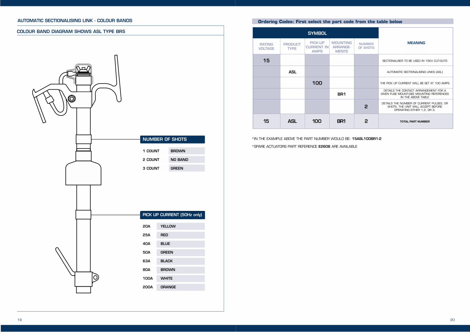
PICK UP CURRENT (50Hz only)
20A YELLOW
25A RED
40A BLUE
50A GREEN
63A BLACK
80A BROWN
100A WHITE
200A ORANGE
NUMBER OF SHOTS
1 COUNT BROWN
2 COUNT NO BAND
3 COUNT GREEN
COLOUR BAND DIAGRAM SHOWS ASL TYPE BR5
AUTOMATIC SECTIONALISING LINK - COLOUR BANDS
19 20
SYMBOL
RATING VOLTAGE
15 SECTIONALISER TO BE USED IN 15KV CUT-OUTS
AUTOMATIC SECTIONALISING LINKS (ASL)
THE PICK UP CURRENT WILL BE SET AT 100 AMPS
DETAILS THE CONTACT ARRANGEMENT FOR AGIVEN FUSE MOUNT.(SEE MOUNTING REFERENCES
IN THE ABOVE TABLE
DETAILS THE NUMBER OF CURRENT PULSES, ORSHOTS, THE UNIT WILL ACCEPT BEFORE
OPERATING EITHER 1,2, OR 3.
ASL
100
BR1
2
PRODUCTTYPE
PICK-UPCURRENT IN
AMPS
MOUNTINGARRANGE-
MENTS
NUMBER OF SHOTS
MEANING
15 ASL 100 BR1 2 TOTAL PART NUMBER
*IN THE EXAMPLE ABOVE THE PART NUMBER WOULD BE: 15ASL100BR1-2
*SPARE ACTUATORS PART REFERENCE E2606 ARE AVAILABLE
Ordering Codes: First select the part code from the table below

21
UPPER CONTACT
LATCHING RING
LATCHING RING
LOWER CONTACT
REPALCEMENT ACCUATOR
NOT VISIBLE.
TYPE ASL XX C: DESIGNED FOR USE WITH NEMA STYLE FUSE MOUNTSNOTES
22

22
HEADQUARTERS
Cooper IndustriesBussmann DivisionP.O. Box 14460St. Louis, Missouri 63178-4460,USA
Telephone: 636 394 2877Facsimile : 800 544 2570International: 636 527 1413Email: [email protected]
COOPER BUSSMANN CHICAGO
175 Hansen Ct. Wood Dale, IL 60191-1145
Telephone: 630 422 2400 Facsimile : 630 422 2500 Email: [email protected]
EUROPEAN HEADQUARTERS
Cooper (UK) LimitedBurton-on-the-WoldsLeicestershire · LE12 5TH UK
Telephone: 44 (0)1509 882 737Facsimile : 44 (0)1509 882 786Email: [email protected] www.bussmann.com
BUSSMANN ASIA-PACIFIC
1 Jalan Kilang Timor# 06-01 Pacific Tech CentreSingapore 159303Republic of Singapore
Telephone: 65 6278 6151Facsimile : 65 6278 3151Email:[email protected]
BUSSMANN AUSTRALIA
Block X391 Park RoadP.O. Box 257Regents Park, SydneyNSW 2143, Australia
Telephone: 612 9743 8333Facsimile : 612 9743 8070
BUSSMANN BRASIL
Bussmann do Brasil LtdaRodovia Santos Dumont, Km 2313 300-000 Cruz das AlmasCabra Postal 95 - ItuSao PauloBrasil
Telephone: 55 11 7824 1856Facsimile : 55 11 7824 1721
BUSSMANN DENMARK
5 LiterbuenDK-2740 SkovlundeCopenhagen, Denmark
Telephone: 45 4485 0900Facsimile : 45 4485 0901Email: [email protected]
BUSSMANN INDIA
2nd Floor, Unit #5White House23-29, St. Marks RoadBangalore-560 001India
Telephone: 91 80 227 0893Facsimile : 91 80 224 0124
BUSSMANN MEXICO
Arrow-Hart, S.A. de C.V.Poniente 148, No 93302300 Mexico, D.F. Mexico
Telephone: 52 5 587 0211Facsimile : 52 5 567 4049
COOPER ELECTRONICTECHNOLOGIES, INC
North America3601 Quantum BoulevardBoynton Beach, Florida 33426
Telephone: +1 561 752 5000Facsimile : +1 561 742 1178
ENBRAY CONTACTORS
Cooper (UK) LimitedUnit 5C, Clay FlattsIndustrial EstateWorkington, CumbriaCA1 3YDUnited Kingdom
Telephone: +44 0 1900 870088Facsimile : +44 0 1900 870099
COOPER BUSSMANN OFFICES AROUND THE WORLD
This bulletin is intended to clearly presentcomprehensive product data and providetechnical information that will help the enduser with design applications. Bussmannreserves the right to change design orconstruction of any products. Bussmann alsoreserves the right to change or update,without notice, any technical informationcontained in this bulletin. Once a product hasbeen selected, it should be tested by the userin all possible applications.
NOTES
23