butter worth analog filter design
TRANSCRIPT
USC Electrical Engineering ELCT 301 Project 4 44#1
© 2001, by T.C. Chandler 1
BUTTERWORTH FILTER DESIGN Objective The main purpose of this laboratory exercise is to learn the procedures for designing Butterworth and Chebyshev filters. In addition, the theory behind these procedures will be discussed in recitation and the hands-on methods practiced in the laboratory. This exercise will focus on the fourth order filter but the methods are valid regardless of the order of the filter. In this lab only even order filters will be considered Background Read pgg.728-738 Hambley. The Butterworth and Chebyshev filters are high order filter designs which have significantly different characteristics, but both can be realized by using simple first order or biquad stages cascaded together to achieve the desired order, passband response, and cut-off frequency. The Butterworth filter has a maximally flat response, i.e., no passband ripple and a roll-off of -20dB per pole. In the Butterworth scheme the designer is usually optimizing the flatness of the passband response at the expense of roll-off. The Chebyshev filter displays a much steeper roll-off, but the gain in the passband is not constant. The Chebyshev filter is characterized by a significant passband ripple that often can be ignored. The designer in this case is optimizing roll-off at the expense of passband ripple.
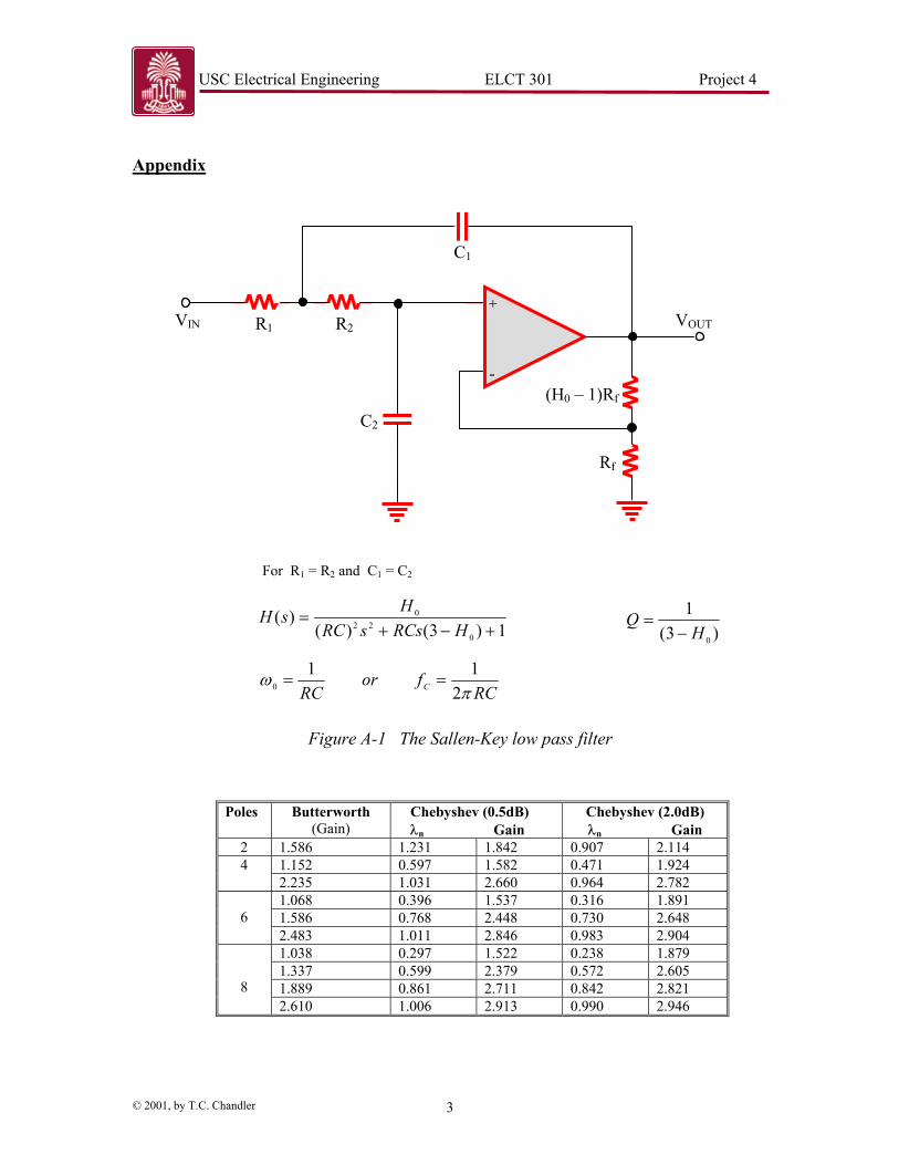
Both filter types can be implemented using the simple Sallen-Key configuration. The Sallen-Key design (shown in Figure A-1) is a biquadratic or biquad type filter, meaning there are two poles defined by the circuit transfer function
1)/)(/1()/(
)(0
20
0
++=
ωω sQsHsH , (1)
where H0 is the DC gain of the biquad circuit and is a function only of the op-amp gain and the value of Rf. The quantity Q is called the quality factor and is a direct measure of the flatness of the passband. When C1 = C2 and R1 = R2 for the Sallen-Key design, the value of Q depends exclusively on the gain of the op-amp stage and the cut-off frequency on R and C, or
)3(
1
0HQ
−= , and (2)
RC
fC π21
= . (3)
Clearly there are many values of Q that will satisfy (1), but the designer must consider, both the quality and the stability of the circuit. Calculations with different values of Q
USC Electrical Engineering ELCT 301 Project 4 44#1
© 2001, by T.C. Chandler 2
will demonstrate that for the second order case the flattest response occurs when Q = .707, hence the maximally flat response of the Butterworth filter will also be realized when Q = .707. In addition the circuit is only stable when H0 < 3. Higher values will result in poles in the right half-plane and an unstable circuit. The Butterworth filter is an optimal filter with maximally flat response in the passband. The magnitude of the frequency response of this family of filters can be written as
( ) n
Cff
HfH2
0
/1)(
+= , (4)
where n is the order of the filter and fc is the cutoff frequency . For a single biquad section, i.e., n = 2, the gain for which Q will equal .707, and hence yield a Butterworth type response, is found to be 1.586. In the case of a fourth order Butterworth filter (n = 4), the correct response can be achieved by cascading two biquad stages. Each stage must be characterized by a specific value of gain (or Q) that achieves both a flat response and stability. For a fourth order Butterworth filter, one stage must have a gain of 1.152 and the other stage a gain of 2.235. The gain values required to cascade biquad sections to achieve even-order filters are shown in Table A-I. Note that the number of biquad stages needed to realize a filter of order n is n/2. Other types of filters such as high pass, and bandpass filters can be designed the same way, i.e., by cascading the appropriate filter sections to achieve the desired bandpass and roll-off. The high pass dual to the Sallen-Key low pass filter can be realized by simply exchanging the positions of R and C in the circuit of Figure A-1. Lab Project
1. Build the Butterworth filters you designed for the Prelab and measure their frequency response.
2. Apply a 1 volt sinusoidal input and observe both the input and output waveforms for ten frequencies equally spaced on the logarithmic scale and measure the response magnitude and phase of each.
3. Compare the response to the model predictions from the prelab.
USC Electrical Engineering ELCT 301 Project 4 44#1
© 2001, by T.C. Chandler 3
Appendix
Poles Butterworth (Gain)
Chebyshev (0.5dB) λn Gain
Chebyshev (2.0dB) λn Gain
2 1.586 1.231 1.842 0.907 2.114 1.152 0.597 1.582 0.471 1.924 4 2.235 1.031 2.660 0.964 2.782 1.068 0.396 1.537 0.316 1.891 1.586 0.768 2.448 0.730 2.648
6
2.483 1.011 2.846 0.983 2.904 1.038 0.297 1.522 0.238 1.879 1.337 0.599 2.379 0.572 2.605 1.889 0.861 2.711 0.842 2.821
8 2.610 1.006 2.913 0.990 2.946
+
-
Rf
(H0 � 1)Rf
C2
C1
R2 R1 VIN VOUT
For R1 = R2 and C1 = C2
1)3()()(
022
0
+−+=
HRCssRCHsH
RCfor
RC C πω
211
0 ==
)3(1
0HQ
−=
Figure A-1 The Sallen-Key low pass filter
USC Electrical Engineering ELCT 301 Project 4 44#1
© 2001, by T.C. Chandler 4
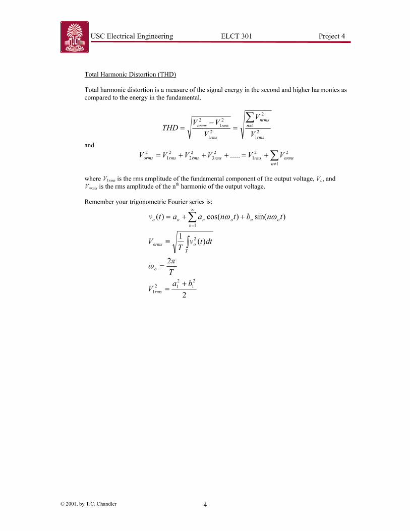
Total Harmonic Distortion (THD) Total harmonic distortion is a measure of the signal energy in the second and higher harmonics as compared to the energy in the fundamental.
21
1
2
21
21
2
rms
nnrms
rms
rmsorms
V
V
VVV
THD∑≠=
−=
and
∑≠
+=+++=1
221
23
22
21
2 .....n
nrmsrmsrmsrmsrmsorms VVVVVV
where V1rms is the rms amplitude of the fundamental component of the output voltage, Vo, and Vnrms is the rms amplitude of the nth harmonic of the output voltage. Remember your trigonometric Fourier series is:
2
2
)(1
)sin()cos()(
21
212
1
2
1
baV
T
dttvT
V
tnbtnaatv
rms
o
Toorms
nononoo
+=
=
≡
++=
∫
∑∞
=
πω
ωω