bvg, bvgf, bva, bvaf, bvh, bvhs, bvhm, ibg, ibgf, iba
TRANSCRIPT
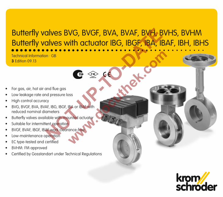
3 Edition 09.13Technical Information · GB
• For gas, air, hot air and flue gas• Low leakage rate and pressure loss• High control accuracy• BVG, BVGF, BVA, BVAF, IBG, IBGF, IBA or IBAF with
reduced nominal diameters• Butterfly valves available with mounted actuator• Suitable for intermittent operation• BVGF, BVAF, IBGF, IBAF work clearance-free• Low-maintenance operation• EC type-tested and certified• BVHM: FM approved• Certified by Gosstandart under Technical Regulations
Butterfly valves BVG, BVGF, BVA, BVAF, BVH, BVHS, BVHMButterfly valves with actuator IBG, IBGF, IBA, IBAF, IBH, IBHS
BV.., IB.. · Edition 09.13 2▼ = To be continued
ContentsButterfly valves BVG, BVGF, BVA, BVAF, BVH, BVHS, BVHM . 1Butterfly valves with actuator IBG, IBGF, IBA, IBAF, IBH, IBHS 1Contents . . . . . . . . . . . . . . . . . . . . . . . . . . . . . . . . . . . . . . . . 21 Application . . . . . . . . . . . . . . . . . . . . . . . . . . . . . . . . . . . . . 41.1 Examples of application. . . . . . . . . . . . . . . . . . . . . . . . . . 71.1.1 IBG, IBGF, lambda correction . . . . . . . . . . . . . . . . . . . . . . . . .71.1.2 IBA, IBAF, adjusting the burner capacity . . . . . . . . . . . . . . . .71.1.3 IBH, hot air compensation . . . . . . . . . . . . . . . . . . . . . . . . . . .81.1.4 IBHS, safety closing function in the event of a mains voltage failure . . . . . . . . . . . . . . . . . . . . . . . . . . . . . . . . . . . . . . . . .81.1.5 BVHM, large number of operating cycles for intermittent operation . . . . . . . . . . . . . . . . . . . . . . . . . . . . . . . . . . . . . . . . . . . . .9
2 Certification . . . . . . . . . . . . . . . . . . . . . . . . . . . . . . . . . . . 102.1 EC type-tested and certified . . . . . . . . . . . . . . . . . . . . . 102.2 FM approved . . . . . . . . . . . . . . . . . . . . . . . . . . . . . . . . . 102.3 Approval for Russia. . . . . . . . . . . . . . . . . . . . . . . . . . . . 10
3 Function . . . . . . . . . . . . . . . . . . . . . . . . . . . . . . . . . . . . . . .114 Replacement possibilities for butterfly valves . . . . . . . . 124.1 DKG is to be replaced by BVG . . . . . . . . . . . . . . . . . . . 124.2 DKL is to be replaced by BVA. . . . . . . . . . . . . . . . . . . . 134.3 K is to be replaced by BVHM . . . . . . . . . . . . . . . . . . . . 144.4 K is to be replaced by BVHS. . . . . . . . . . . . . . . . . . . . . 15
5 Flow rate . . . . . . . . . . . . . . . . . . . . . . . . . . . . . . . . . . . . . 165.1 Flow rate curves for BVG, BVGF, BVA, BVAF. . . . . . . . . 165.1.1 With full bore = nominal diameter . . . . . . . . . . . . . . . . . . . . 165.1.2 With 1 x reduced bore . . . . . . . . . . . . . . . . . . . . . . . . . . . . . 175.1.3 With 2 × reduced bore . . . . . . . . . . . . . . . . . . . . . . . . . . . . . 185.1.4 kV values . . . . . . . . . . . . . . . . . . . . . . . . . . . . . . . . . . . . . . . . 19
5.2 Flow rate curves for BVH, BVHM, BVHS. . . . . . . . . . . . 205.2.1 kV values . . . . . . . . . . . . . . . . . . . . . . . . . . . . . . . . . . . . . . . . 21
6 Selection . . . . . . . . . . . . . . . . . . . . . . . . . . . . . . . . . . . . . 226.1 Type code . . . . . . . . . . . . . . . . . . . . . . . . . . . . . . . . . . . . 226.2 IBG, IBGF, IBA, IBAF, IBH, IBHS . . . . . . . . . . . . . . . . . . . 23
6.2.1 Type code . . . . . . . . . . . . . . . . . . . . . . . . . . . . . . . . . . . . . . 246.3 Determining the nominal size . . . . . . . . . . . . . . . . . . . 256.3.1 Calculating the nominal size . . . . . . . . . . . . . . . . . . . . . . . 256.3.2 BVG, BVGF, BVA, BVAF. . . . . . . . . . . . . . . . . . . . . . . . . . . . 266.3.3 BVH, BVHS, BVHM . . . . . . . . . . . . . . . . . . . . . . . . . . . . . . . .27
7 Project planning information . . . . . . . . . . . . . . . . . . . . . 297.1 Installation . . . . . . . . . . . . . . . . . . . . . . . . . . . . . . . . . . . 297.2 Flow velocities in pipes . . . . . . . . . . . . . . . . . . . . . . . . . 307.3 Actuator selection . . . . . . . . . . . . . . . . . . . . . . . . . . . . . 317.3.1 IC 20, IC 40 . . . . . . . . . . . . . . . . . . . . . . . . . . . . . . . . . . . . . . 317.3.2 MB 7 . . . . . . . . . . . . . . . . . . . . . . . . . . . . . . . . . . . . . . . . . . 33
8 Accessories . . . . . . . . . . . . . . . . . . . . . . . . . . . . . . . . . . . 348.1 For BVG, BVA . . . . . . . . . . . . . . . . . . . . . . . . . . . . . . . . . 348.2 For BVG, BVGF, BVA, BVAF, BVH and BVHS. . . . . . . . . 358.3 For BVH, BVHM and BVHS . . . . . . . . . . . . . . . . . . . . . . 358.4 For BVHM. . . . . . . . . . . . . . . . . . . . . . . . . . . . . . . . . . . . 35
9 Technical data . . . . . . . . . . . . . . . . . . . . . . . . . . . . . . . . . 369.1 BVG, BVGF, BVA, BVAF. . . . . . . . . . . . . . . . . . . . . . . . . . 369.2 BVH, BVHM, BVHS. . . . . . . . . . . . . . . . . . . . . . . . . . . . . 369.3 IC 20, IC 20..E . . . . . . . . . . . . . . . . . . . . . . . . . . . . . . . . 379.3.1 IC 20 . . . . . . . . . . . . . . . . . . . . . . . . . . . . . . . . . . . . . . . . . . .379.3.2 IC 20..E . . . . . . . . . . . . . . . . . . . . . . . . . . . . . . . . . . . . . . . . .37
9.4 IC 40. . . . . . . . . . . . . . . . . . . . . . . . . . . . . . . . . . . . . . . . 389.5 Dimensions of IBG/IBA (BVG/BVA + IC 20/IC 40) . . . . 399.5.1 With full bore = nominal diameter . . . . . . . . . . . . . . . . . . 399.5.2 With 1 × reduced bore . . . . . . . . . . . . . . . . . . . . . . . . . . . . 399.5.3 With 2 × reduced bore . . . . . . . . . . . . . . . . . . . . . . . . . . . 39
9.6 Dimensions of IBGF/IBAF (BVGF/BVAF + IC 20/IC 40) 409.6.1 With full bore = nominal diameter . . . . . . . . . . . . . . . . . . 409.6.2 With 1 × reduced bore . . . . . . . . . . . . . . . . . . . . . . . . . . . . 409.6.3 With 2 × reduced bore . . . . . . . . . . . . . . . . . . . . . . . . . . . 40
9.7 Dimensions of IBH/IBHS (BVH/BVHS + IC 20/IC 40) . . 419.8 Dimensions MB 7 + BVHM . . . . . . . . . . . . . . . . . . . . . . 429.9 Conversion factors . . . . . . . . . . . . . . . . . . . . . . . . . . . . 43

BV.., IB.. · Edition 09.13 3▼ = To be continued
10 Maintenance cycles . . . . . . . . . . . . . . . . . . . . . . . . . . . . 4410.1 Butterfly valves BVG, BVGF, BVA, BVAF, BVH, BVHM, BVHS. . . . . . . . . . . . . . . . . . . . . . . . . . . . . . . . . . . . . . . . . . . 4410.2 Actuators IC 20, IC 40 . . . . . . . . . . . . . . . . . . . . . . . . . 44
11 Glossary . . . . . . . . . . . . . . . . . . . . . . . . . . . . . . . . . . . . . 4511.1 Control characteristic, valve authority . . . . . . . . . . . . . 4511.2 Interpolation (linear) . . . . . . . . . . . . . . . . . . . . . . . . . . . 4511.3 Hot air compensation . . . . . . . . . . . . . . . . . . . . . . . . . 4511.4 Symbols in acc. with DIN EN 334/14382 and DVGW G 491 . . . . . . . . . . . . . . . . . . . . . . . . . . . . . . . . . . . . 45
Feedback . . . . . . . . . . . . . . . . . . . . . . . . . . . . . . . . . . . . . . 46Contact . . . . . . . . . . . . . . . . . . . . . . . . . . . . . . . . . . . . . . . . 46
Contents
BV.., IB.. · Edition 09.13 4
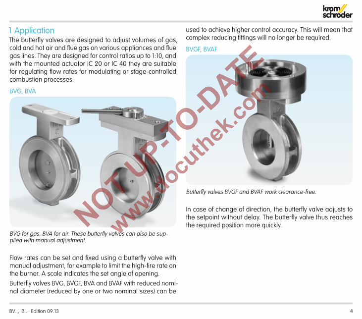
1 ApplicationThe butterfly valves are designed to adjust volumes of gas, cold and hot air and flue gas on various appliances and flue gas lines. They are designed for control ratios up to 1:10, and with the mounted actuator IC 20 or IC 40 they are suitable for regulating flow rates for modulating or stage-controlled combustion processes.
BVG, BVA
BVG for gas, BVA for air. These butterfly valves can also be sup-plied with manual adjustment.
Flow rates can be set and fixed using a butterfly valve with manual adjustment, for example to limit the high-fire rate on the burner. A scale indicates the set angle of opening.Butterfly valves BVG, BVGF, BVA and BVAF with reduced nomi-nal diameter (reduced by one or two nominal sizes) can be
used to achieve higher control accuracy. This will mean that complex reducing fittings will no longer be required.
BVGF, BVAF
Butterfly valves BVGF and BVAF work clearance-free.
In case of change of direction, the butterfly valve adjusts to the setpoint without delay. The butterfly valve thus reaches the required position more quickly.

BV.., IB.. · Edition 09.13 5
BVH
BVH, BVHM, BVHS for hot air and flue gas
The butterfly valve BVH is used for processes that require the very precise adjustment of the flow rate or low leakage. In conjunction with the stop bar, the valve disc ensures very low leakage rates.Using a spiral spring which compensates for the play in com-bination with the actuator IC 40, it is possible to move the valve disc to the required angle with almost zero hysteresis.
BVHSThe butterfly valve BVHS with safety closing function, see page 11 (Function), is used with the actuator IC 40S in systems where it is important that in the event of a mains voltage fail-ure the valve closes preventing air streaming into the furnace without being under control.In order to maximize the service life of the butterfly valve, the safety closing function should be used only for the scheduled closing function and not for controlled shut-down or for inter-mittent switching of the burner.
BVHMWell suited to intermittent operation due to the large number of operating cycles in conjunction with the solenoid actuator MB 7.
Application
BV.., IB.. · Edition 09.13 6
BVG, BVABVGF, BVAF
IBGF, IBAF
BVH, BVHS
IC
IBH, IBHS
IBG, IBA
Application
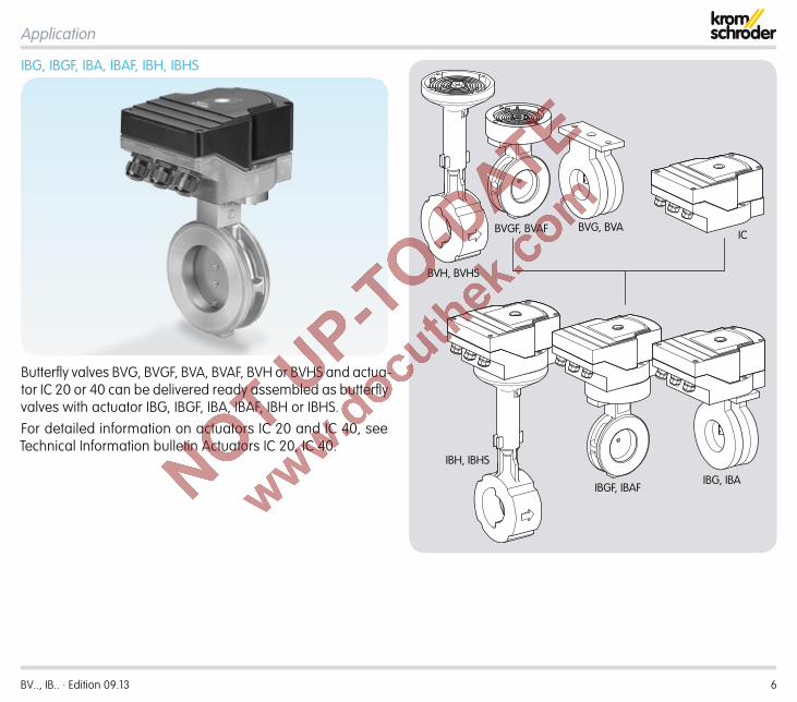
IBG, IBGF, IBA, IBAF, IBH, IBHS
Butterfly valves BVG, BVGF, BVA, BVAF, BVH or BVHS and actua-tor IC 20 or 40 can be delivered ready assembled as butterfly valves with actuator IBG, IBGF, IBA, IBAF, IBH or IBHS.For detailed information on actuators IC 20 and IC 40, see Technical Information bulletin Actuators IC 20, IC 40.

BV.., IB.. · Edition 09.13 7
VAG
BVA
M
IBA
M
IBG
VAG
BVA
M
IBA
4 – 20 mA
1 .1 Examples of application1 .1 .1 IBG, IBGF, lambda correctionIf the burner is to be operated with excess gas or air for reasons of the process operation, the butterfly valve with actuator IBG can be used to correct the lambda value.The butterfly valve BVA with manual adjustment is used to adjust the high-fire rate.
1 .1 .2 IBA, IBAF, adjusting the burner capacityIn pneumatic ratio control systems, the butterfly valve with mounted actuator IBA determines the air volume for the re-quired burner capacity.The butterfly valve BVA with manual adjustment is used to adjust the high-fire rate.
Application

BV.., IB.. · Edition 09.13 8
VAG
BVA
M
IBHS
1 .1 .3 IBH, hot air compensationThe butterfly valve with actuator IBH is used on burners that are operated with preheated combustion air at temperatures of up to 450°C (840°F). Hot air compensation, see page 45 (Glossary).
1 .1 .4 IBHS, safety closing function in the event of a mains voltage failureThe safety closing function ensures that in the event of a mains voltage failure air cannot stream into the furnace without be-ing under control.The butterfly valve with actuator IBHS is used in the air circuit.The butterfly valve BVA with manual adjustment is used to adjust the high-fire rate.
Application > Examples of application
VAG +VAS 1
M
IBH
GIK
WPS
Twopoint
BV.., IB.. · Edition 09.13 9
VAG
BVAMB 7 + BVHM
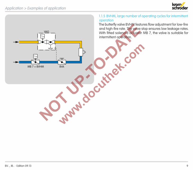
1 .1 .5 BVHM, large number of operating cycles for intermittent operationThe butterfly valve BVHM features flow adjustment for low-fire and high-fire rate. The valve stop ensures low leakage rates. With fitted solenoid actuator MB 7, the valve is suitable for intermittent operation.
Application > Examples of application

BV.., IB.. · Edition 09.13 10
2 Certification2 .1 EC type-tested and certified BVG, BVGF
pursuant to– Gas Appliances Directive (2009/142/EC) in conjunction
with EN 161
2 .2 FM approvedBVHM
Factory Mutual Research Class: 7400 Process Control Valves.Designed for applications pursuant to NFPA 85 and NFPA 86.www.approvalguide.com
2 .3 Approval for RussiaBVG, BVGF, BVA, BVAF, BVH, BVHS, BVHM
Certified by Gosstandart under Technical Regulations.Approved by Rostekhnadzor (RTN).Scan of the approval for Russia (RUS) – see www.docuthek.com ➔ Elster Kromschröder ➔ Kromschröder, LBE ➔ Products ➔ 03 Valves and butterfly valves ➔ Butterfly valves BVG, BVA, BVH ➔ Kind of document: Certificate ➔ BV... B00069 (nationales Zertifikat Russland) (RUS)
BV.., IB.. · Edition 09.13 11
3 FunctionBVG, BVGF, BVA, BVAF, BVH, BVHM, BVHSThe butterfly valves are designed on the basis of the free-flow principle (no deflection of the flow). They release a cross-section for the flowing medium, depending on a rotary movement between 0 and 90°.The butterfly valves BVG, BVGF, BVA and BVAF are with valve disc clearance. BVH is equipped with a mechanical stop bar. The valve disc of the butterfly valves BVH, BVHS, BVHM fea-tures a twin disc and, together with the mechanical stop bar, ensures very low leakage.BVG, BVGF, BVA, BVAF and BVH are specifically designed to fit the Elster Kromschröder actuators IC 20 and IC 40. The butterfly valves feature very easy action. Consequently, the actuator requires only a low torque.BVHM is tailored to the Elster Kromschröder solenoid actua-tor MB 7.
BVG, BVAButterfly valves with reduced nominal diameter (reduced by up to two nominal sizes) can be used to achieve higher control accuracy. This will mean that expensive reducing fittings will no longer be required.Various adapter sets with square shaft, free shaft end or lever are available as accessories, see page 34 (Accessories). Flow rates can be set and fixed using a lever, for example to limit the high-fire rate on the burner. A scale indicates the set angle of opening.
BVGF, BVAFThe spiral spring always pushes the valve disc in the direc-tion of closing. Any clearance between the actuator and the valve disc is eliminated and the control command is executed without delay.
BVHM, BVHSThe butterfly valves BVHM, BVHS feature a safety closing func-tion. They are used in systems where it is important that in the event of a mains voltage failure the valve closes preventing air streaming into the furnace without being under control.A pre-tensioned spiral spring moves the valve disc against the mechanical stop of the butterfly valve in the event of a solenoid valve/motor defect, within the closing time.The safety closing function of butterfly valve BVHS is possible only in conjunction with the actuator IC 40S.

BV.., IB.. · Edition 09.13 12
4 Replacement possibilities for butterfly valves4 .1 DKG is to be replaced by BVG
Type TypeDKG Butterfl y valve Butterfl y valve BVG25 DN 25 –32 DN 32 –40 DN 40 DN 40 4050 DN 50 DN 50 5065 DN 65 DN 65 6580 DN 80 DN 80 80100 DN 100 DN 100 100125 DN 125 DN 125 125150 DN 150 DN 150 150
/15-/125 Reduced to nominal size DN Reduced to nominal size DN /25-/125T T-productZ For fi tting between two DIN fl anges For fi tting between two fl anges to EN 1092 Z
W For fi tting between two ANSI fl anges For fi tting between two ANSI fl anges W03 pu max. 300 mbar (4.35 psi) pu max. 500 mbar (7.25 psi) 05H With manual adjustment Adapter set with manual adjustment HV With square shaft Adapter set with square shaft VF With free shaft end Adapter set with free shaft end F
60 Temperature range: 60°C (140°F) Temperature range: 60°C (140°F)
D With disc clearance With disc clearance
DKG 80Z03H60D Example Example BVG 80Z05H
standard, available

BV.., IB.. · Edition 09.13 13
Replacement possibilities for butterfly valves
4 .2 DKL is to be replaced by BVAType TypeDKL Butterfl y valve Butterfl y valve BVA25 DN 25 –32 DN 32 –40 DN 40 DN 40 4050 DN 50 DN 50 5065 DN 65 DN 65 6580 DN 80 DN 80 80100 DN 100 DN 100 100125 DN 125 DN 125 125150 DN 150 DN 150 150
/15-/125 Reduced to nominal size DN Reduced to nominal size DN /25-/125T T-product – –
Z For fi tting between two DIN fl anges For fi tting between two fl anges to EN 1092 Z
W For fi tting between two ANSI fl anges For fi tting between two ANSI fl anges W
03 pu max. 300 mbar (4.35 psi) pu max. 500 mbar (7.25 psi) 05H With manual adjustment Adapter set with manual adjustment HV With square shaft Adapter set with square shaft VF With free shaft end Adapter set with free shaft end F
100 Temperature range: 100°C (210°F) Temperature range: 60°C (140°F)
D With disc clearance With disc clearance
DKL 40Z03F100D Example Example BVA 40Z05F
standard, available

BV.., IB.. · Edition 09.13 14
Replacement possibilities for butterfly valves
4 .3 K is to be replaced by BVHMType Type
K Valve Butterfl y valve for solenoid actuator MB 7 BVHM40* DN 40 DN 40 4050 DN 50 DN 50 5065 DN 65 DN 65 6580 DN 80 DN 80 80100 DN 100 DN 100 100
T T-productZ For fi tting between two DIN fl anges For fi tting between two fl anges to EN 1092 ZW For fi tting between two ANSI fl anges For fi tting between two ANSI fl anges W
pu max. 130 mbar (1.89 psig) pu max. 150 mbar (2.18 psig) 01 Temperature range: 0 – 550°C (0 – 1020°F) Temperature range: 0 – 450°C (0 – 840°F)
A With stop With stop A
K 80ZA Example Example BVHM 80Z01A
* Nominal size DN 40 only with disc clearance standard, available
BV.., IB.. · Edition 09.13 15
Replacement possibilities for butterfly valves
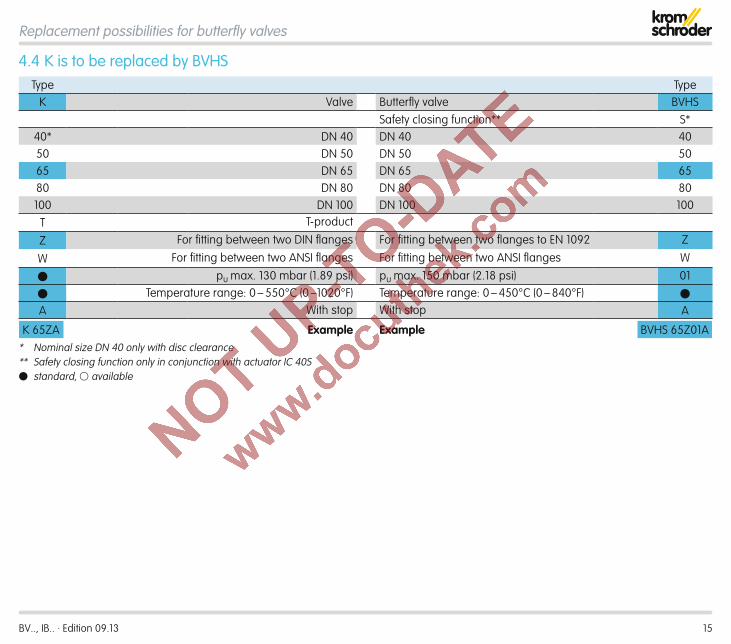
4 .4 K is to be replaced by BVHSType Type
K Valve Butterfl y valve BVHSSafety closing function** S*
40* DN 40 DN 40 4050 DN 50 DN 50 5065 DN 65 DN 65 6580 DN 80 DN 80 80100 DN 100 DN 100 100
T T-product
Z For fi tting between two DIN fl anges For fi tting between two fl anges to EN 1092 Z
W For fi tting between two ANSI fl anges For fi tting between two ANSI fl anges W
pu max. 130 mbar (1.89 psi) pu max. 150 mbar (2.18 psi) 01
Temperature range: 0 – 550°C (0 –1020°F) Temperature range: 0 – 450°C (0 – 840°F)
A With stop With stop A
K 65ZA Example Example BVHS 65Z01A* Nominal size DN 40 only with disc clearance** Safety closing function only in conjunction with actuator IC 40S standard, available
BV.., IB.. · Edition 09.13 16
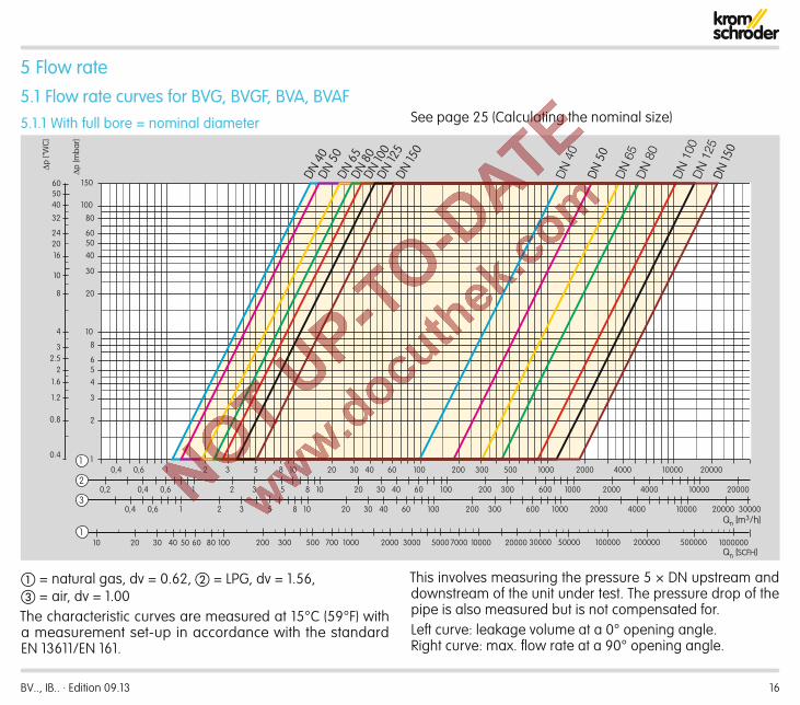
= natural gas, dv = 0.62, = LPG, dv = 1.56, = air, dv = 1.00The characteristic curves are measured at 15°C (59°F) with a measurement set-up in accordance with the standard EN 13611/EN 161.
This involves measuring the pressure 5 × DN upstream and downstream of the unit under test. The pressure drop of the pipe is also measured but is not compensated for.Left curve: leakage volume at a 0° opening angle. Right curve: max. flow rate at a 90° opening angle.
5 Flow rate5 .1 Flow rate curves for BVG, BVGF, BVA, BVAF5 .1 .1 With full bore = nominal diameter
10 20 30 40 60 100 200
8 10 20 30 40 60 100 200 300
8 10 20 30 40 60 100 200
Qn [m3/h]
Qn [SCFH]
1000
600 1000
300 600
2000300 500 4000
2000 4000
1000
10000
20000
100002000
10000
4000
20000 30000
20000
0,4 0,6 1 2 3 5 81
2
30,4 0,6 1 2 3 50,2
0,4 0,6 1 2 3 5
1
2
3
456
8
10
20
30
405060
80
100
150
0.8
1.2
1.62
2.53
4
8
10
16
24
32
0.4
40
60
∆p ["
WC
]
50
20
200 300 700 1000 2000 3000 7000 10000 20000500 5000 30000 50000 100000 20000020 30 40 50 60 80 10010 500000 10000001
∆p [m
bar]
DN 4
0DN
50
DN 6
5DN
80
DN 10
0DN
125
DN 15
0
DN
40
DN 5
0D
N 6
5 D
N 8
0
DN
100
D
N 1
25
DN 15
0
See page 25 (Calculating the nominal size)

BV.., IB.. · Edition 09.13 17
= natural gas, dv = 0.62 = LPG, dv = 1.56, = air, dv = 1.00The characteristic curves are measured at 15°C (59°F) with a measurement set-up in accordance with the standard EN 13611/EN 161.
This involves measuring the pressure 5 × DN upstream and downstream of the unit under test. The pressure drop of the pipe is also measured but is not compensated for.Left curve: leakage volume at a 0° opening angle. Right curve: max. flow rate at a 90° opening angle. See page 25 (Calculating the nominal size)
Flow rate > Flow rate curves for BVG, BVGF, BVA, BVAF
5 .1 .2 With 1 × reduced bore
10 20 30 40 60 100 200
8 10 20 30 40 60 100 200 300
8 10 20 30 40 60 100 200
1000
600 1000
300 600
2000 300 500 4000
2000 4000
1000
10000
10000 2000
10000
4000
0,4 0,6 1 2 3 5 8 1
2
3 0,4 0,6 1 2 3 5 0,2
0,4 0,6 1 2 3 5
1
2
3
4
5 6
8
10
20
30
40
50 60
80
100
150
∆p [m
bar]
20000
20000 30000
20000
Qn [m3/h]
DN 4
0/32
DN 5
0/40
DN
65/
50
DN 8
0/65
DN
100
/80
DN 1
25/1
00
DN 1
50/1
25
DN
40/
32
DN
50/
40
DN
65/
50
DN
80/
65
DN
100
/80
DN
125
/100
D
N 1
50/1
25
P1
BV.., IB.. · Edition 09.13 18
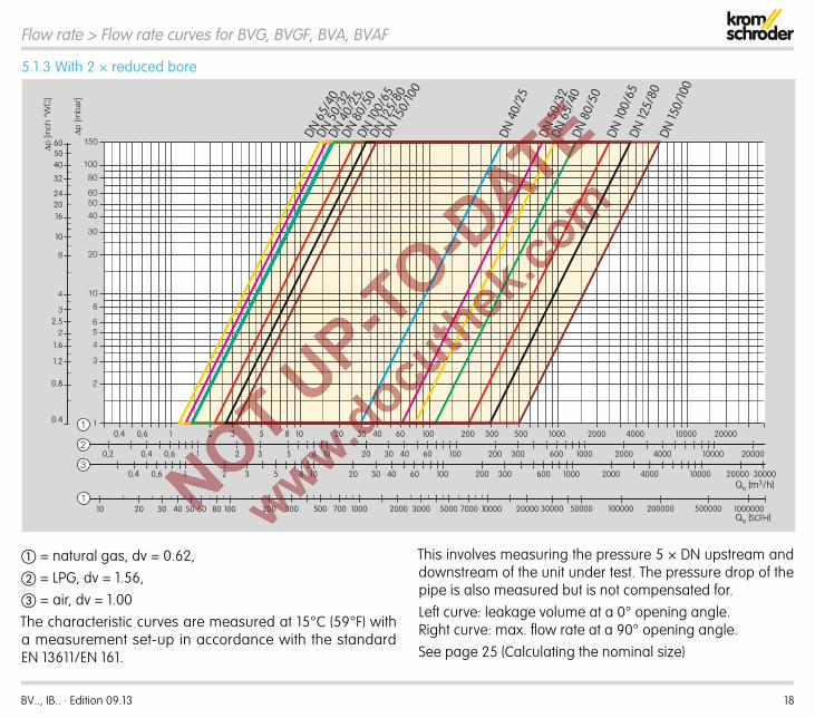
= natural gas, dv = 0.62, = LPG, dv = 1.56, = air, dv = 1.00The characteristic curves are measured at 15°C (59°F) with a measurement set-up in accordance with the standard EN 13611/EN 161.
This involves measuring the pressure 5 × DN upstream and downstream of the unit under test. The pressure drop of the pipe is also measured but is not compensated for.Left curve: leakage volume at a 0° opening angle. Right curve: max. flow rate at a 90° opening angle.See page 25 (Calculating the nominal size)
Flow rate > Flow rate curves for BVG, BVGF, BVA, BVAF
5 .1 .3 With 2 × reduced bore
10 20 30 40 60 100 200
8 10 20 30 40 60 100 200 300
8 10 20 30 40 60 100 200
1000
600 1000
300 600
2000300 500 4000
2000 4000
1000
10000
20000
100002000
10000
4000
20000 30000
20000
0,4 0,6 1 2 3 5 81
0,4 0,6 1 2 3 50,2
0,4 0,6 1 2 3 5
1
2
3
4
5 6
8
10
20
30
40
50 60
80
100
150
2
3
DN 4
0/25
,DN
80/
50DN
100/
65
DN 5
0/32
DN 6
5/40
DN 12
5/80
DN 15
0/10
0
DN 4
0/25
DN 5
0/32
DN 6
5/40
DN 8
0/50
DN 10
0/65
DN 12
5/80
DN 15
0/10
0
0.8
1.2
1.62
2.53
4
8
10
16
24
32
0.4
40
60∆p [i
nch
"WC
]
50
20
200 300 700 1000 2000 3000 7000 10000 20000500 5000 30000 50000 100000 20000020 30 40 50 60 80 10010 500000 10000001
∆p [m
bar
]
Qn [m3/h]
Qn [SCFH]

BV.., IB.. · Edition 09.13 19
5 .1 .4 kV valuesWith full bore = nominal diameter
Opening angle0 10° 20° 30° 40° 50° 60° 70° 80° 90°
BVG/BVGF/BVA/BVAF 40 1.0 1.5 3.6 7.3 13 23 37 56 77 90BVG/BVGF/BVA/BVAF 50 1.2 1.6 4.0 9.3 17 31 51 82 123 167BVG/BVGF/BVA/BVAF 65 1.7 2.7 7.3 16 32 57 94 144 210 281BVG/BVGF/BVA/BVAF 80 2.1 3.2 9.8 24 47 83 132 202 296 405BVG/BVGF/BVA/BVAF 100 2.5 3.4 12 33 59 133 214 331 517 792BVG/BVGF/BVA/BVAF 125 3.4 7.4 25 78 145 244 385 583 910 1132BVG/BVGF/BVA/BVAF 150 4.7 13 58 132 229 369 583 882 1557 1696
With 1 × reduced boreBVG/BVGF/BVA/BVAF 40/32 1.2 1.4 2.8 5.4 9.5 16 27 41 57 63BVG/BVGF/BVA/BVAF 50/40 1.1 1.5 3.2 7.1 13 21 34 52 73 90BVG/BVGF/BVA/BVAF 65/50 1.3 1.6 4.3 9.5 17 29 46 68 97 120BVG/BVGF/BVA/BVAF 80/65 2.0 2.4 7.0 16 31 55 89 132 185 243BVG/BVGF/BVA/BVAF 100/80 2.4 3.3 9.8 23 49 88 140 203 275 335BVG/BVGF/BVA/BVAF 125/100 2.9 5.2 17 48 103 173 262 364 478 561BVG/BVGF/BVA/BVAF 150/125 3.8 6.6 25 89 180 288 422 586 771 940
With 2 × reduced boreBVG/BVGF/BVA/BVAF 40/25 1.3 1.3 2.2 3.9 6.6 11 16 20 24 27BVG/BVGF/BVA/BVAF 50/32 1.2 1.4 2.8 5.4 9.6 16 26 38 50 56BVG/BVGF/BVA/BVAF 65/40 1.1 1.5 3.3 7.1 13 20 32 46 61 71BVG/BVGF/BVA/BVAF 80/50 1.3 1.6 4.0 9.0 16 28 44 64 85 101BVG/BVGF/BVA/BVAF 100/65 2.0 2.9 7.7 17 32 55 86 122 162 185BVG/BVGF/BVA/BVAF 125/80 2.4 3.4 8.7 22 47 85 133 185 237 273BVG/BVGF/BVA/BVAF 150/100 2.9 4.2 15 42 95 160 237 319 397 458
Flow rate > Flow rate curves for BVG, BVGF, BVA, BVAF

BV.., IB.. · Edition 09.13 20
For air, dv = 1.00The characteristic curves are measured at 15°C (59°F) with a measurement set-up in accordance with the standard EN 13611/EN 161.The pressure is measured 5 × DN upstream and downstream
of the unit under test. The pressure drop of the pipe is also measured but is not compensated for.Left curve: leakage volume at a 0° opening angle. Right curve: max. flow rate at a 90° opening angle.See page 25 (Calculating the nominal size)
Flow rate
5 .2 Flow rate curves for BVH, BVHM, BVHS
2
3
456
810
20
30
405060
80
1
100
150
4 5 6 7 8 10 20 30 40 60 100 200 300 500 20001 2 3 10000,50,2 0,3 5000
BVH/
BVHM
/BVH
S 40
BVH/
BVHS
50BV
H/BV
HS 65
, BVH
M 50
BVHS
80BV
H 80
, BVH
S 65
BVHS
100
BVH
100,
BVHM
80
BVH/
BVHM
/BVH
S 80
BVH/
BVHM
/BVH
S 65
BVH/
BVHM
/BVH
S 50
BVH/
BVHM
/BVH
S 40
BVHM
100
∆p [m
bar]
207 30 50 10010 200 400 2000 5000 100001000 20000 50000 100000 200000
0.8
1.2
1.62
2.53
4
8
10
16
24
32
0.4
40
60
50
20
BVH/
BVHM
/BVH
S 100
Qn [m3/h]
∆p ["
WC]
Air Qn [SCFH]

BV.., IB.. · Edition 09.13 21
5 .2 .1 kV valuesOpening angle
0° 10° 20° 30° 40° 50° 60° 70° 80° 90°BVH 40 0.4 6.4 12 18 24 31 38 47 53 55BVH 50 0.5 10 19 29 40 56 73 95 116 120BVH 65 0.7 12 21 32 48 67 92 128 156 160BVH 80 0.8 20 34 52 73 103 143 192 238 250BVH 100 1.1 27 47 74 111 170 255 374 525 560
BVHM 40 0.4 6.4 12 18 24 31 38 47 53 55BVHM 50 0.5 10 19 29 40 56 73 95 116 120BVHM 65 0.7 12 21 32 48 67 92 128 156 160BVHM 80 1.1 20 34 52 73 103 143 192 238 250BVHM 100 2.1 27 47 74 111 170 255 374 525 560
BVHS 40 0.4 6.4 12 18 24 31 38 47 53 55BVHS 50 0.5 10 19 29 40 56 73 95 116 120BVHS 65 0.7 12 21 32 48 67 92 128 156 160BVHS 80 0.8 20 34 52 73 103 143 192 238 250BVHS 100 1.1 27 47 74 111 170 255 374 525 560
Flow rate > Flow rate curves for BVH, BVHM, BVHS
BV.., IB.. · Edition 09.13 22
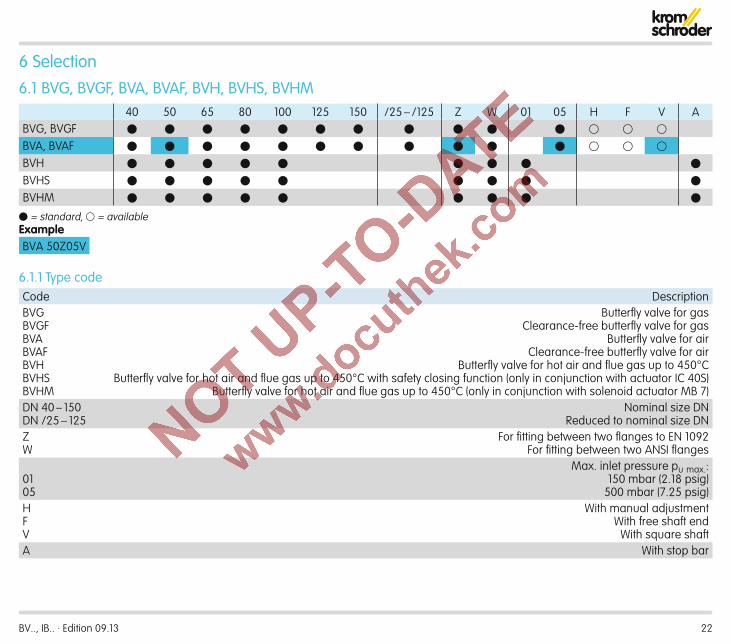
6 Selection6 .1 BVG, BVGF, BVA, BVAF, BVH, BVHS, BVHM
40 50 65 80 100 125 150 /25 – /125 Z W 01 05 H F V ABVG, BVGF
BVA, BVAF
BVH
BVHS
BVHM
= standard, = availableExampleBVA 50Z05V
6 .1 .1 Type codeCode DescriptionBVGBVGFBVABVAFBVHBVHSBVHM
Butterfl y valve for gasClearance-free butterfl y valve for gas
Butterfl y valve for airClearance-free butterfl y valve for air
Butterfl y valve for hot air and fl ue gas up to 450°CButterfl y valve for hot air and fl ue gas up to 450°C with safety closing function (only in conjunction with actuator IC 40S)
Butterfl y valve for hot air and fl ue gas up to 450°C (only in conjunction with solenoid actuator MB 7)DN 40 – 150DN /25 – 125
Nominal size DN Reduced to nominal size DN
ZW
For fi tting between two fl anges to EN 1092For fi tting between two ANSI fl anges
0105
Max. inlet pressure pu max.:150 mbar (2.18 psig)
500 mbar (7.25 psig)HFV
With manual adjustmentWith free shaft end
With square shaftA With stop bar
BV.., IB.. · Edition 09.13 23
Selection
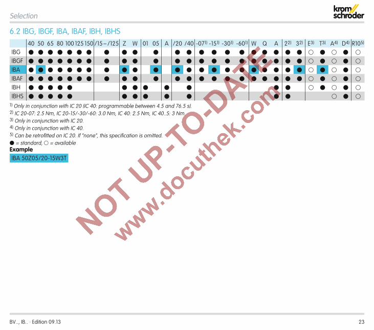
6 .2 IBG, IBGF, IBA, IBAF, IBH, IBHS40 50 65 80 100 125 150 /15 – /125 Z W 01 05 A /20 /40 -071) -151) -301) -601) W Q A 22) 32) E3) T3) A4) D4) R105)
IBG
IBGF
IBA
IBAF
IBH
IBHS 1) Only in conjunction with IC 20 (IC 40: programmable between 4.5 and 76.5 s).2) IC 20-07: 2.5 Nm, IC 20-15/-30/-60: 3.0 Nm, IC 40: 2.5 Nm, IC 40..S: 3 Nm.3) Only in conjunction with IC 20.4) Only in conjunction with IC 40.5) Can be retrofi tted on IC 20. If “none”, this specifi cation is omitted. = standard, = availableExampleIBA 50Z05/20-15W3T
BV.., IB.. · Edition 09.13 24
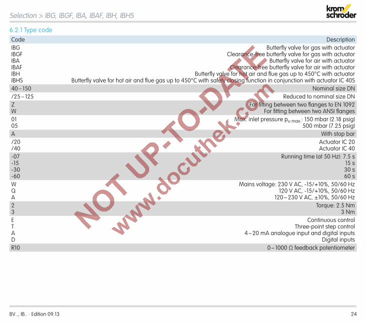
6 .2 .1 Type codeCode DescriptionIBGIBGFIBAIBAFIBHIBHS
Butterfl y valve for gas with actuatorClearance-free butterfl y valve for gas with actuator
Butterfl y valve for air with actuatorClearance-free butterfl y valve for air with actuator
Butterfl y valve for hot air and fl ue gas up to 450°C with actuatorButterfl y valve for hot air and fl ue gas up to 450°C with safety closing function in conjunction with actuator IC 40S
40 – 150 Nominal size DN/25 – 125 Reduced to nominal size DNZW
For fi tting between two fl anges to EN 1092For fi tting between two ANSI fl anges
0105
Max. inlet pressure pu max.: 150 mbar (2.18 psig)500 mbar (7.25 psig)
A With stop bar/20/40
Actuator IC 20Actuator IC 40
-07-15-30-60
Running time (at 50 Hz): 7.5 s15 s30 s60 s
WQA
Mains voltage: 230 V AC, -15/+10%, 50/60 Hz120 V AC, -15/+10%, 50/60 Hz
120 – 230 V AC, ±10%, 50/60 Hz23
Torque: 2.5 Nm3 Nm
ETAD
Continuous controlThree-point step control
4 – 20 mA analogue input and digital inputsDigital inputs
R10 0 – 1000 Ω feedback potentiometer
Selection > IBG, IBGF, IBA, IBAF, IBH, IBHS

BV.., IB.. · Edition 09.13 25
Δp v[°]
Q min. a
BVG/BVGFBVH/BVHS
BVA/BVAFBVHM
Δpmín.
metric imperial
Enter densityFlow rate Q (standard)
Outlet pressure pd
Medium temperature
Flow rate Q (operation)
Product
6 .3 Determining the nominal size6 .3 .1 Calculating the nominal size
Δp = pressure drop when valve fully opened (90°)Qmin. = leakage rate when valve closed (Δp0° = pu)a = valve authority (recommended value: 0.3)
= opening angle at entered Δpmax.v = flow velocity
Δpmax.
Selection

BV.., IB.. · Edition 09.13 26
6 .3 .2 BVG, BVGF, BVA, BVAF∆p on the butterfly valve is determined using the control char-acteristic a, see page 45 (Glossary), and the outlet pressure pd for normal operation.
a = ∆p100%/inlet pressure pu
A control characteristic of a = 0.3 provides good control prop-erties.
0
BVG, BVGF,BVA, BVAF
900
100
a > 0.3a < 0.3
a = 0.3
[°]
Q [%
]
ExampleWe want to find ∆p100% in order to select the nominal size DN of the butterfly valve BVA for air to be used for modulating control of a gas burner:Outlet pressure: pd = 30 mbar Air flow rate at standard conditions: Qn = 1000 m3/h Control characteristic: a = 0.3
∆p100% =a × pd
1 - a
∆p100% =0.3 × 30 mbar
= 12.9 mbar = 13 mbar1 - 0.3
The flow velocity in the pipes exercises a considerable influ-ence on the pressure loss and the noise development. When designing the butterfly valve, it is recommended that the flow velocity of 30 m/s is not exceeded, see page 30 (Flow ve-locities in pipes).A flow rate at standard conditions Qn = 1000 m3/h results in a pipe of DN 100.Select the required nominal size from the flow rate diagram on the basis of the desired flow rate Qn and the calculated ∆p100%.
ResultA butterfly valve with 1 × reduced bore is selected in order to obtain the pressure loss ∆p100% = 13 mbar that has been cal-culated taking into account the selected nominal size DN = 100.DN ➔ BVA 100/80 – see P1, Flow rate, Flow rate curves for BVG, BVGF, BVA, BVAF on page 17 (With 1 × reduced bore).
Selection > Determining the nominal size

BV.., IB.. · Edition 09.13 27
Selection > Determining the nominal size
6 .3 .3 BVH, BVHS, BVHMWe want to find a butterfly valve BVH for staged control of a gas burner. In order to regulate accurately between loads, the opening angle for high-fire and low-fire rates is calculated using the kV value.
Selecting the high-fire opening angleFirstly, ∆pHF is determined using the control characteristic a, see page 45 (Glossary), and the outlet pressure pd HF.
a = ∆p100%/inlet pressure pu
A control characteristic of a = 0.3 provides good control prop-erties.
0 900
100
a > 0,3a < 0,3
a = 0,3
[°]
Q [%
]
BVH, BVHS,BVHM
ExampleOutlet pressure for high fire: pd HF = 30 mbar Outlet pressure pd HF absolute: 1.013 + 30 = 1.043 bar High-fire flow rate at standard conditions: Qn HF = 430 m3/h Density ρn for air: 1.29 kg/m3 Air temperature: 35°C (95°F) Control characteristic: a = 0.3
∆pHF =a × pd HF
1 - a
∆pHF =0.3 × 30 mbar
= 13 mbar = 0.013 bar1 - 0.3
kV · 514
514 · ρn · T/(∆pHF · pd HF absolute)
ρn · T/(∆pHF · pd HF absolute)
kV =Qn
Qn =
Tabsolute = 35 + 273 K = 308 K
·430514
1.293 · 3080.013 · 1.043
kV =
kV = 144 Select the next largest kV value in the kV values table for the BVH, BVHS design, allowing for the maximum opening angle. An opening angle greater than 60° should be selected in order to achieve a wider control range.For example, the selected kV value for the butterfly valve BVH, DN 65 with 80° opening is ➔ kV = 156 – see Flow rate, Flow rate curves for BVH, BVHM, BVHS on page 21 (kV values).The ranges between the opening angles, which are listed in the kV values table in 10° steps, can be considered as linear. After linear interpolation of the kV values between 70° and 80°, the selected opening angle of the butterfly valve BVH for high fire is: kV = 145 ➔ approx. 76°.Then check the flow velocity: max. 30 m/s.
BV.., IB.. · Edition 09.13 28
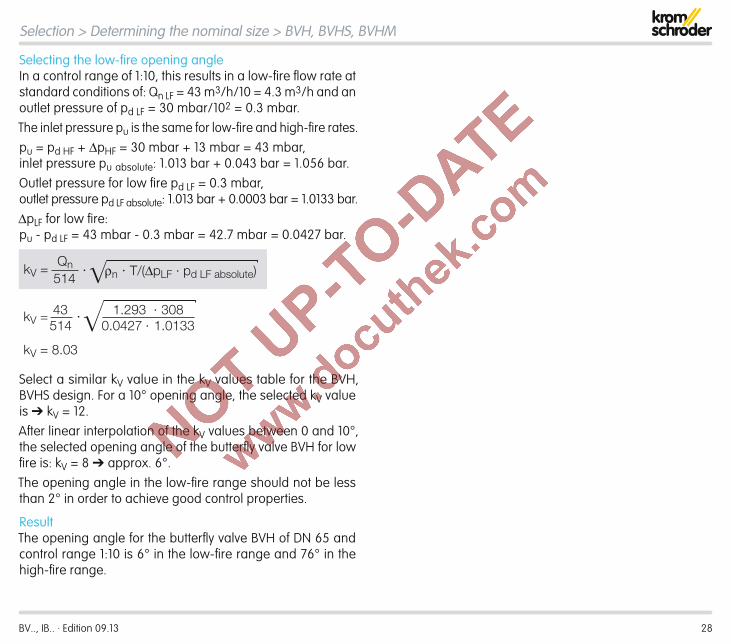
Selecting the low-fire opening angleIn a control range of 1:10, this results in a low-fire flow rate at standard conditions of: Qn LF = 43 m3/h/10 = 4.3 m3/h and an outlet pressure of pd LF = 30 mbar/102 = 0.3 mbar.The inlet pressure pu is the same for low-fire and high-fire rates.pu = pd HF + ∆pHF = 30 mbar + 13 mbar = 43 mbar, inlet pressure pu absolute: 1.013 bar + 0.043 bar = 1.056 bar.Outlet pressure for low fire pd LF = 0.3 mbar, outlet pressure pd LF absolute: 1.013 bar + 0.0003 bar = 1.0133 bar.∆pLF for low fire: pu - pd LF = 43 mbar - 0.3 mbar = 42.7 mbar = 0.0427 bar.
·43514
1.293 · 3080.0427 · 1.0133
kV =
kV = 8.03
514 · ρn · T/(∆pLF · pd LF absolute)kV =Qn
·43514
1.293 · 3080.0427 · 1.0133
kV =
kV = 8.03
514 · ρn · T/(∆pLF · pd LF absolute)kV =Qn
Select a similar kV value in the kV values table for the BVH, BVHS design. For a 10° opening angle, the selected kV value is ➔ kV = 12.After linear interpolation of the kV values between 0 and 10°, the selected opening angle of the butterfly valve BVH for low fire is: kV = 8 ➔ approx. 6°.The opening angle in the low-fire range should not be less than 2° in order to achieve good control properties.
ResultThe opening angle for the butterfly valve BVH of DN 65 and control range 1:10 is 6° in the low-fire range and 76° in the high-fire range.
Selection > Determining the nominal size > BVH, BVHS, BVHM

BV.., IB.. · Edition 09.13 29
7 Project planning information7 .1 InstallationThe butterfly valve must be installed in-between two flanges in accordance with EN 1092, PN 16. The length of the inlet and outlet section should be 2 × DN.When designing the pipe, it is recommended that a flow veloc-ity of 30 m/s (5905 ft/min) is not exceeded, see page 30 (Flow velocities in pipes).
Installation position
The actuator must be installed in the vertical or horizontal position, not upside down. When built into a vertical pipe, dirt may accumulate on the stop bar, which may prevent the valve from closing properly. This is why we recommend selecting the direction of flow from bottom to top.If pipe fittings (reducing fittings) are installed in the pipework, the additional pressure loss must be taken into account.If the valve is used with hot air, the pipeline should be ad-equately insulated so as to reduce the ambient temperature – the flanges and the butterfly valves BVH, BVHS or BVHM must be kept free of insulating material. Install the butterfly valve in such a way that rising hot air does not circulate around the actuator.
Butterfly valves BVG, BVGF, BVA, BVAF and BVH and actuators IC 20 and IC 40 are supplied separately or assembled. Easy assembly with the actuator using 2 screws can be carried out either before or after installation of the butterfly valve in the pipework.The butterfly valve BVHM and the solenoid actuator MB 7 are delivered separately. Easy assembly with the solenoid actuator using the installation set can be carried out either before or after installation of the butterfly valve in the pipework.In conjunction with butterfly valves BVH, BVHS or BVHM for hot air, the actuators can be used in temperatures of up to 250°C (480°F), with additional heat deflectors they can be used in temperatures of up to 450°C (840°F).
BV.., IB.. · Edition 09.13 30
Project planning information
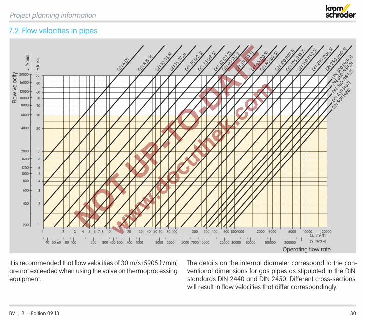
7 .2 Flow velocities in pipes
2
3
4
5
6
8
10
20
30
40
50
60
80
4 5 6 7 8 10 20 30 40 50 60 80 100 200 300 400
1
1 2 3 600 8001000 2000 3000 6000 10000
100
v [m
/s]
20000
40 50 60 80 100 200 700300 400 500 2000 3000 5000 7000 100001000 20000 30000 50000 100000 200000
400
600
800
1000
1200
1600
2000
4000
6000
8000
12000
16000
200
20000
10000
v [ft
/min
]
Qb [m3/h]Qb [SCFH]
Flow
vel
ocity
Operating flow rate
DN 6 (7)
DN 8 (9.
9)DN 10
(13.6
)DN 15
(17.3
)DN 20
(22.3
)DN 25
(28.5
)DN 32
(37.2
)DN 40
(43.1
)DN 50
(54.5
)DN 65
(70.3
)DN 80
(82.5
)
DN 125 (
131.7
)
DN 300 (
309.7
)
DN 350 (
339.6
)
DN 400 (
389.2
)
DN 450 (
437)
DN 500 (
486)
DN 100 (
107.1
)DN 15
0 (15
9.3)
DN 200 (
206,5
)DN 25
0 (26
0.4)
It is recommended that flow velocities of 30 m/s (5905 ft/min) are not exceeded when using the valve on thermoprocessing equipment.
The details on the internal diameter correspond to the con-ventional dimensions for gas pipes as stipulated in the DIN standards DIN 2440 and DIN 2450. Different cross-sections will result in flow velocities that differ correspondingly.

BV.., IB.. · Edition 09.13 31
7 .3 Actuator selectionButterfly valves BVG, BVGF, BVA, BVAF and BVH are controlled by actuator IC 20 or IC 40.Butterfly valve BVHS is controlled by actuator IC 40S.Butterfly valve BVHM is controlled by solenoid actuator MB 7.
7 .3 .1 IC 20, IC 40The characteristic curves relate to the maximum torque pro-duced by the flow rate. In general, maximum torque is reached at approx. 70°.
IC 20The running time of the actuator per 90° depends on the re-quired torque.Example: Any running time could be used for a butterfly valve BVG of nominal size DN 65.The running time is reduced by a factor of 0.83 at a frequency of 60 Hz on the actuator.
IC 40Torque and running time are mutually independent on actua-tors IC 40 and IC 40S.
Project planning information
IC 40
1 2 2,51,50,5 30
∆p 10
0 [mba
r]
0102030405060708090
100110120130140150
DN 150
DN 125
DN 10
0
DN 8
0
DN
65
IC 20-07; 60 Hz
IC 40SIC 20-15, IC 20-30, IC 20-60; 50/60 Hz
IC 20-07; 50 Hz
1 21,50,50
[Nm]
[lbf ft]
∆p 10
0 [psi
]
0
0.2
0.4
0.6
0.8
1
1.2
1.4
1.6
1.8
2
Torque
IC 40
0 1 1,50,5 2 2,5 30
102030405060708090
100110120130140150
DN 8
0
DN
65
IC 20-07; 60 Hz
IC 40SIC 20-15, IC 20-30, IC 20-60; 50/60 Hz
IC 20-07; 50 Hz
[Nm]
[lbf ft]
0
0.2
0.4
0.6
0.8
1
1.2
1.4
1.6
1.8
2
DN 10
0
DN 125
DN 150
∆p 10
0 [mba
r]
∆p 10
0 [psi
]
1 21,50,50Torque
BVG, BVA
BVGF, BVAF

BV.., IB.. · Edition 09.13 32
IC 40
1 2 2,51,50,5 300
102030405060708090
100110120130140150 IC 20-07; 60 Hz
IC 40SIC 20-15, IC 20-30, IC 20-60; 50/60 Hz
IC 20-07; 50 Hz
DN
50
DN
40
DN
65
DN 8
0
DN 100
1 21,50,50 [lbf ft]
0
0.2
0.4
0.6
0.8
1
1.2
1.4
1.6
1.8
2
[Nm]
MB 7; 50/60 Hz
∆p 10
0 [mba
r]
∆p 10
0 [psi
]
Torque
BVH, BVHS
Project planning information > Actuator selection > IC 20, IC 40

BV.., IB.. · Edition 09.13 33
MB 7..N MB 7..R, MB 7..L
7 .3 .2 MB 7MB 7..N: quick opening: < 1 s,
quick closing: < 1 s,MB 7..R: slow opening: 2 – 4 s,
slow closing: 2 – 4 s,MB 7..L: slow opening: 2 – 4 s,
quick closing: < 1 s.
0,4 0,8 10,60,200
102030405060708090
100110120130140150 MB 7
DN 5
0
DN
40
DN 65
DN 80
DN 100
0,4 0,60,20 [lbf ft]
0
0.2
0.4
0.6
0.8
1
1.2
1.4
1.6
1.8
2
[Nm]
∆p 10
0 [mba
r]
∆p 10
0 [psi
]
Torque
BVHM
Project planning information > Actuator selection

BV.., IB.. · Edition 09.13 34
8 mm(0.31")
M6
90 0,2
(3.54 0.01 ")
ø130(5.12")
40(1.57")
20(0.78")
10(0.39")
ø 10 h9
0.39" h9
M6
90 0,2
(3.54 0.01 ")
ø130(5.12")
40(1.57")
35(1.38")
20(0.78")
M6
90 0,2
(3.54 0.01 ")
ø130(5.12")
40(1.57")
20(0.78")
8 Accessories8 .1 For BVG, BVAAdapter set with square shaftThis adapter set is required if the butterfly valve is mounted onto actuators other than IC. The actuator must have a square shaft end.
Adapter set Order No.Enclosed 74921674
Adapter set with free shaft endThis adapter set is required if the butterfly valve is mount-ed onto actuators other than IC. The actuator must have a Ø 10 mm shaft end.
Adapter set Order No.Enclosed 74921676
Adapter set with manual adjustmentThis adapter set is required if the butterfly valve is to be opened and closed manually. The valve can be locked in position.
Adapter set Order No.Enclosed 74921678

BV.., IB.. · Edition 09.13 35
∅ 5,5 mm∅ 0.21"220 mm
8.66"
110 mm4.33"2 ×
8 .3 For BVH, BVHM and BVHSHeat deflectorsButterfly valves BVH, BVHM or BVHS for hot air can be used in temperatures of up to 250°C (480°F), with additional heat deflectors they can be used in temperatures of up to 450°C (840°F).Order number: 74921670
Accessories
8 .4 For BVHMFastening setThis is required to attach the solenoid actuator MB 7 to the butterfly valve BVHM. The fastening set is delivered enclosed as an additional item.Order number: 74922222
8 .2 For BVG, BVGF, BVA, BVAF, BVH and BVHSFastening setTo attach an IC 20 or IC 40 to the butterfly valve. If the actua-tor and butterfly valve are pre-assembled, the fastening set will already be fitted; otherwise, it will be enclosed as an ad-ditional item.
Fastening set Order No.IC – BVA/BVG/BVH /B (enclosed) 74921082

BV.., IB.. · Edition 09.13 36
9 Technical data9 .1 BVG, BVGF, BVA, BVAFGas type:BVG, BVGF: natural gas, town gas, LPG and other non-aggressive fuel gases.BVGF: biologically produced methane (max. 0.1 %-by-vol. H2S).BVA, BVAF: air.The gas must be dry in all conditions and must not contain condensate.Housing material: AlSi, valve disc: aluminium, drive shaft: stainless steel, seals: HNBR.DN: 40 to 150, reduction by 2 nominal sizes is possible.Inlet pressure pu: max. 500 mbar (7.25 psi).Medium temperature: -20 to +60°C (-4 to +140°F), ambient temperature: -20 to +60°C (-4 to +140°F).
9 .2 BVH, BVHM, BVHSGas type: air and flue gas.DN: 40 to 100.Housing material: GGG, valve disc: stainless steel, drive shaft: stainless steel.Inlet pressure pu: max. 150 mbar (2.16 psi). Pressure differential between inlet pressure pu and outlet pressure pd: max. 150 mbar (2.16 psi).Medium temperature: -20 to +450°C (-4 to +840°F), ambient temperature:
-20 to +60°C (-4 to +140°F).
BV.., IB.. · Edition 09.13 37
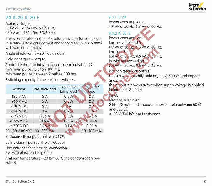
9 .3 IC 20, IC 20 . .EMains voltage: 120 V AC, -15/+10%, 50/60 Hz, 230 V AC, -15/+10%, 50/60 Hz.Screw terminals using the elevator principles for cables up to 4 mm2 (single core cables) and for cables up to 2.5 mm2 with wire end ferrules.Angle of rotation: 0 – 90°, adjustable.Holding torque = torque.Control by three-point step signal to terminals 1 and 2: minimum pulse duration: 100 ms, minimum pause between 2 pulses: 100 ms.Switching capacity of the position switches:
Voltage Resistive load Incandescent lamp load
Inductive load
125 V AC 2 A 0.5 A 2 A250 V AC 2 A 0.5 A 2 A< 30 V DC 2 A 2 A 2 A< 50 V DC 1 A 0.4 A 1 A< 75 V DC 0.75 A 0.3 A 0.75 A< 125 V DC 0.5 A 0.2 A 0.03 A< 250 V DC 0.25 A 0.1 A 0.03 A
12 – 30 V AC/DC 10 – 100 mA – 10 – 100 mAEnclosure: IP 65 pursuant to IEC 529.Safety class: I pursuant to EN 60335.Line entrance for electrical connection: 3 × M20 plastic cable glands.Ambient temperature: -20 to +60°C, no condensation per-mitted.
9 .3 .1 IC 20Power consumption: 4.9 VA at 50 Hz, 5.8 VA at 60 Hz.
9 .3 .2 IC 20 . .EPower consumption: terminals 1, 2 and 5: 4.9 VA at 50 Hz, 5.8 VA at 60 Hz, terminal 3: 8.4 VA at 50 Hz, 9.5 VA at 60 Hz, in total not exceeding: 8.4 VA at 50 Hz, 9.5 VA at 60 Hz.Position feedback output: 4 – 20 mA, electrically isolated, max. 500 Ω load imped-ance. The output is always active when supply voltage is applied to terminals 3 and 4.Input: electrically isolated, 0 (4) – 20 mA: load impedance switchable between 50 Ω and 250 Ω, 0 – 10 V: 100 kΩ input resistance.
Technical data

BV.., IB.. · Edition 09.13 38
9 .4 IC 40Mains voltage: IC 40: 100 – 230 V AC, ±10%, 50/60 Hz; the actuator auto-matically adjusts to the respective mains voltage.Power consumption: 8.4 W, switch-on peak current: max. 8 A for max. 10 ms.Screw terminals using the elevator principles for cables up to 4 mm2 (single core cables) and for cables up to 2.5 mm2 with wire end ferrules.Angle of rotation: 0 – 90°.Holding torque = torque as long as permanent supply volt-age is applied.2 digital inputs: IC 40: 24 V DC or 100 – 230 V AC each. Current requirement of digital inputs: 3 mA ± 1.5 mA.1 analogue input (optional): 4 – 20 mA (internal load imped-ance: max. 500 Ω at 20 mA).Potentiometer (optional): 1000 Ω +/- 20%, linearity tolerance +/- 2%, max. capacity 0.25 W, conductive plastic element.Important: tap wiper at high resistance.2 digital outputs: Signalling contacts designed as relay change-over contacts. Contact current of digital outputs: min. 5 mA (resistive) and max. 2 A.The relay contacts can be connected to 100 – 230 V AC or 24 V DC. If the contacts have been connected with a volt-age > 24 V and a current > 0.1 A once, the gold plating on the contacts will have been burnt through. This contact can
then only be connected with this power rating or higher power rating.2 LED status displays:– Blue LED for operation “ON”;
drive in motion = slow flashing light; manual operation = fast flashing light; drive stopped = permanent light.
– Red LED for warnings and faults; warning = permanent light; fault = flashing light.
– Red and blue LED simultaneously, calibration in progress = flashing light.
Enclosure: IP 65 pursuant to IEC 529.Safety class: I pursuant to EN 60335.Line entrance for electrical connection: 3 × M20 plastic cable glands.Ambient temperature: -20 to +60°C, no condensation per-mitted.
Technical data

BV.., IB.. · Edition 09.13 39
Technical data
9 .5 .2 With 1 × reduced bore
TypeWeightkg (lbs)
IBG/IBA 40/32 2.7 (5.95)IBG/IBA 50/40 2.9 (6.39)IBG/IBA 65/50 3.2 (7.05)IBG/IBA 80/65 3.4 (7.49)IBG/IBA 100/80 3.6 (7.93)IBG/IBA 125/100 4.1 (9.04)IBG/IBA 150/125 4.4 (9.70)
9 .5 .3 With 2 × reduced bore
TypeWeightkg (lbs)
IBG/IBA 40/25 2.8 (6.17)IBG/IBA 50/32 3.0 (6.61)IBG/IBA 65/40 3.2 (7.05)IBG/IBA 80/50 3.5 (7.70)IBG/IBA 100/65 3.8 (8.38)IBG/IBA 125/80 4.4 (9.70)IBG/IBA 150/100 4.9 (10.80)
9 .5 .1 With full bore = nominal diameter
TypeWeightkg (lbs)
IBG/IBA 40 2.7 (5.95)IBG/IBA 50 2.8 (6.17)IBG/IBA 65 3.0 (6.61)IBG/IBA 80 3.2 (7.05)IBG/IBA 100 3.3 (7.27)IBG/IBA 125 3.6 (7.93)IBG/IBA 150 3.9 (8.60)
9 .5 Dimensions of IBG/IBA (BVG/BVA + IC 20/IC 40)
Type
H2 H3 DIN ANSI
mm (inch)
mm (inch)
D1 mm
(inch)
D1 mm
(inch)
D2 mm
(inch)
IBG/IBA 40 96 (3.78)
52 (2.05)
92 (3.62)
92 (3.62)
85.7 (3.37)
IBG/IBA 50 100 (3.94)
59 (2.32)
107 (4.21)
107 (4.21)
105 (4.13)
IBG/IBA 65 108 (4.25)
69 (2.72)
127 (5)
127 (5)
124 (4.88)
IBG/IBA 80 115 (4.53)
76 (2.99)
142 (5.59)
142 (5.59)
137 (5.39)
IBG/IBA 100 125 (4.92)
86 (3.39)
162 (6.38)
162 (6.38) –
IBG/IBA 125 138 (5.43)
101 (3.98)
192 (7.56)
192 (7.56) –
IBG/IBA 150 150 (5.9)
114 (4.49)
218 (8.58)
218 (8.58) –
D1 42(1 .65")
H2
H3
86 (3 .38")
97 (3 .81")
132 (5 .2")
2,0 kg (4 .4 lbs)
103
(4 .05")
D2

BV.., IB.. · Edition 09.13 40
9 .6 .1 With full bore = nominal diameter
TypeWeightkg (lbs)
IBGF/IBAF 40 3.5 (7.70)IBGF/IBAF 50 3.6 (7.93)IBGF/IBAF 65 3.8 (8.38)IBGF/IBAF 80 4.0 (8.82)IBGF/IBAF 100 4.1 (9.04)IBGF/IBAF 125 4.4 (9.70)IBGF/IBAF 150 4.7 (10.36)
9 .6 .2 With 1 × reduced bore
TypeWeightkg (lbs)
IBGF/IBAF 40/32 3.5 (7.70)IBGF/IBAF 50/40 3.7 (8.16)IBGF/IBAF 65/50 4.0 (8.82)IBGF/IBAF 80/65 4.1 (9.04)IBGF/IBAF 100/80 4.4 (9.70)IBGF/IBAF 125/100 4.9 (10.80)IBGF/IBAF 150/125 5.2 (11.46)
9 .6 .3 With 2 × reduced bore
TypeWeightkg (lbs)
IBGF/IBAF 40/25 3.6 (7.93)IBGF/IBAF 50/32 3.8 (8.38)IBGF/IBAF 65/40 4.0 (8.82)IBGF/IBAF 80/50 4.3 (9.48)IBGF/IBAF 100/65 4.6 (10.14)IBGF/IBAF 125/80 5.2 (11.46)IBGF/IBAF 150/100 5.7 (12.57)
Technical data
9 .6 Dimensions of IBGF/IBAF (BVGF/BVAF + IC 20/IC 40)
Type
H2 H3 DIN ANSI
mm (inch)
mm (inch)
D1 mm
(inch)
D1 mm
(inch)
D2 mm
(inch)
IBGF/IBAF 40 134 (5.28)
52 (2.05)
92 (3.62)
92 (3.62)
85.7 (3.37)
IBGF/IBAF 50 138 (5.43)
59 (2.32)
107 (4.21)
107 (4.21)
105 (4.13)
IBGF/IBAF 65 146 (5.74)
69 (2.72)
127 (5.00)
127 (5.00)
124 (4.88)
IBGF/IBAF 80 153 (6.02)
76 (2.99)
142 (5.59)
142 (5.59)
137 (5.39)
IBGF/IBAF 100 163 (6.41)
86 (3.39)
162 (6.38)
162 (6.38) –
IBGF/IBAF 125 176 (6.93)
101 (3.98)
192 (7.56)
192 (7.56) –
IBGF/IBAF 150 188 (7.40)
114 (4.49)
218 (8.58)
218 (8.58) –
42(1 .65")
H2
H3
97(3 .81")
86(3 .38")
132(5 .2")
2,0 kg(4 .4 lbs)
103(4 .05")
D1
D2

BV.., IB.. · Edition 09.13 41
Technical data
9 .7 Dimensions of IBH/IBHS (BVH/BVHS + IC 20/IC 40)
H2
H3 D2 D1
97 (3 .81")
103
(4 .05")
86 (3 .38") 132
(5 .2")
2,0 kg (4 .4 lbs)
42 (1 .65")
TypeH2 H3 DIN ANSI Weight
mm (inch) mm (inch) D1 mm (inch)
D2 mm (inch)
D1 mm (inch)
D2 mm (inch) kg (lbs)
IBH/IBHS 40 234 (9.2) 46 (1.8) 92 (3.6) – 92 (3.6) 85.7 (3.4) 5.4 (11.9)IBH/IBHS 50 239 (9.4) 54 (2.1) 107 (4.2) – 107 (4.2) 105 (4.1) 5.9 (13.0)IBH/IBHS 65 243 (9.5) 64 (2.5) 127 (5.0) – 127 (5.0) 124 (4.9) 6.8 (15.0)IBH/IBHS 80 254 (10) 71 (2.8) 142 (5.6) – 142 (5.6) 137 (5.4) 7.3 (16.1)IBH/IBHS 100 265 (10.4) 88 (3.4) 175 (6.9) 162 (6.4) 175 (6.9) – 8.5 (18.7)

BV.., IB.. · Edition 09.13 42
Technical data
9 .8 Dimensions of MB 7 + BVHM
D242 mm(1.65")
D1
130 mm(5.12")H4
329,3 mm(12.96")
123
mm
(4.8
4")
F
262,5 mm(10.33")
H2
H3
D242 mm(1.65")
D1
130 mm(5.12")H4
329,3 mm(12.96")
123
mm
(4.8
4")
F
262,5 mm(10.33")
H2
H3
TypeH2 H3 H4 DIN ANSI F Weight
mm (inch) mm (inch) mm (inch) D1 mm (inch)
D2 mm (inch)
D1 mm (inch)
D2 mm (inch) mm (inch) kg (lbs)
BVHM 40 + MB 7 234 (9.21) 46 (1.81) 91.5 (3.58) 92 (3.6) – 92 (3.6) 85.7 (3.37) 92 (3.62) 11.79 (26.00)BVHM 50 + MB 7 239 (9.40) 54 (2.12) 91.5 (3.58) 107 (4.2) – 107 (4.2) 105 (4.13) 92 (3.62) 12.17 (26.83)BVHM 65 + MB 7 243 (9.56) 64 (2.51) 91.5 (3.58) 127 (5.0) – 127 (5.0) 124 (4.88) 92 (3.62) 13.05 (28.77)BVHM 80 + MB 7 254 (10.00) 71 (2.80) 91.5 (3.58) 142 (5.6) – 142 (5.6) 137 (5.39) 92 (3.62) 13.59 (29.96)BVHM 100 + MB 7 265 (10.43) 88 (3.46) 91.5 (4.33) 175 (6.9) 162 (6.4) 175 (6.9) – 92 (3.62) 14.97 (33.00)

BV.., IB.. · Edition 09.13 43
Technical data
9 .9 Conversion factors
SI unit × multiplier = US unitm3/h 35.31 SCFH
bar 14.5 psi
mbar 0.0145 psi
mbar 0.39 "WCmm 0.039 inch
kg 2.2 lbslitres 0.26 gal
m/s 3.28 ft/s
US unit × multiplier = SI unitSCFH 0.0283 m3/h
psi 0.0689 barpsi 68.89 mbar
"WC 2.54 mbarinch 25.4 mm
lbs 0.45 kggal 3.79 litresft/s 0.3048 m/s
°C = (°F - 32) × 5/9
°F = (°C × 9/5) + 32
BV.., IB.. · Edition 09.13 44
10 Maintenance cycles10 .1 Butterfly valves BVG, BVGF, BVA, BVAF, BVH, BVHM, BVHSThe butterfly valves BVG, BVGF, BVA, BVAF, BVH, BVHM and BVHS require little maintenance.We recommend a function check once a year.BVG, BVGF: check for external tightness once a year.BVGF: if operated with biologically produced methane, a tight-ness test and function check must be carried out every six months.
10 .2 Actuators IC 20, IC 40The actuators IC 20, IC 40 suffer little wear and require little servicing.We recommend a function check once a year.
IC 40A service note is issued after 3 million cycles (0 – 90 – 0°/0 – 100 – 0%), 3 million relay switching operations, 5 million changes of direction.

BV.., IB.. · Edition 09.13 45
11 Glossary11 .1 Control characteristic, valve authorityIn order for the butterfly valve to be able to influence the flow rate, a proportion of the pressure loss ∆p from the entire system has to be caused by the butterfly valve. Taking into consideration that the overall pressure loss ∆p should be kept to a minimum, a valve authority a = 0.3 is recommended for the butterfly valve.This means that of the overall pressure loss ∆p there is a 30% drop on the fully open butterfly valve.
11 .2 Interpolation (linear)Mathematical production of interim values at equal distance to the adjacent value.
11 .3 Hot air compensationThe volume of air increases with the addition of hot air. The oxygen content contained in the air reduces with every m3. In order to maintain a constant oxygen content, additional air has to be added to the combustion gas.
11 .4 Symbols in acc . with DIN EN 334/14382 and DVGW G 491Comparison of the new and old symbols
Name of the variable Old NewInlet pressure pe puOutlet pressure pa pd

BV.., IB.. · Edition 09.13
Finally, we are offering you the opportunity to assess this “Technical Information (TI)” and to give us your opinion, so that we can improve our documents further and suit them to your needs.
ClarityFound information quicklySearched for a long timeDidn’t find informationWhat is missing?
ComprehensionCoherentToo complicatedNo answer
ScopeToo littleSufficientToo wideNo answer
No answer
NavigationI can find my way aroundI got “lost”No answer
UseTo get to know the productTo choose a productPlanningTo look for information
My scope of functionsTechnical departmentSalesNo answer
Remarks
(Adobe Reader 7 or higher required) www.adobe.com
Elster GmbH Postfach 2809 · 49018 Osnabrück Strotheweg 1 · 49504 Lotte (Büren) GermanyT +49 541 1214-0 F +49 541 1214-370 [email protected] www.elster.com
The current addresses of our international agents are available on the Internet:www.kromschroeder.de/index.php?id=718&L=1
We reserve the right to make technical modifications in the interests of progress.Copyright © 2013 Elster Group All rights reserved.
Feedback
Contact
0325
0551