bvp blood pump e - harvard apparatus manuals/b… · hugo sachs elektronik - harvard a p p a r a t...
TRANSCRIPT
HUGO SACHS ELEKTRONIK - HARVARD A P P A R A T U S GmbH, Gruenstrasse 1, D-79232 March-Hugstetten, Germany
BVP-BP Operating instructions page 1
Contents
Introduction, manufacturer’s details ........................................................................................... ...................... 2
Copyright ......................................................................................................................................................... 2
Trademarks ...................................................................................................................................................... 2
Preliminary notes on the pump system ........................................................................................... ................. 2
Read these Operating Instructions! ................................................................................................................. 2
Range of application and safety precautions ................................................................................................... 2
Warning note ................................................................................................................................................... 3
Warranty .......................................................................................................................................................... 3
List of items supplied ....................................................................................................................................... 3
Operating panel ............................................................................................................................................... 4
Back of unit ...................................................................................................................................................... 4
Supply voltage ................................................................................................................................................. 4
Altering the supply voltage 115V/230V and changing the fuses. ...................................................................... 5
Starting up ....................................................................................................................................................... 5
Switching on .................................................................................................................................................... 5
Analogue interface connector .......................................................................................................................... 6
Internal adjustments ........................................................................................................................................ 6
Centrifugal pump heads................................................................................................................................... 7
Pump head BP-50 and BP-80...................................................................................................... .................... 7
Output characteristic of a BP-80 ...................................................................................................................... 8
Fitting and removing the BP-80 ....................................................................................................................... 8
Pump head SP-45 ........................................................................................................................................... 9
Output characteristic of SP-45 ................................................................................................. ........................ 9
Fitting the adapter SP-03 for head SP-45 ...................................................................................................... 10
Inserting the pump head SP-45 ..................................................................................................................... 10
Operating notes ............................................................................................................................................. 11
Repairs .......................................................................................................................................................... 11
Spares ........................................................................................................................................................... 11
Maintenance and cleaning ....................................................................................................... ...................... 11
Technical data ................................................................................................................................................ 11
Reply form ..................................................................................................................................................... 12
Index .............................................................................................................................................................. 13
OPERATING INSTRUCTIONSfor the
Pump Drive BVP-BP for centrifugal blood pump headsBP-50/BP-80 and SP-45
(Revision 1.0 / 6 / 00 / Steiert, translation: Linton)
HUGO SACHS ELEKTRONIK - HARVARD A P P A R A T U S GmbH, Gruenstrasse 1, D-79232 March-Hugstetten, Germany
BVP-BP Operating instructions page 2
Introduction, manufacturer’s detailsThese Operating Instructions describe the function andthe use of the pump drive BVP-BP. They represent anessential part of the apparatus and must be kept closeto the apparatus, accessible to all users.
All the information in these Instructions has beenassembled after careful examination but does notrepresent any warranty of product properties. Alterat-ions in line with technical progress are reserved.
HSE-HARVARD obtains the basic unit of the drive fromIsmatec and modifies it so that the Bio-Pump(R)centrifugal blood pump heads BP-50 and BP-80 byMedtronic can be used, as well as the pump head SP-45 by Terumo (using a suitable adapter).
Responsible for the modified drive:
HUGO SACHS ELEKTRONIK -HARVARD APPARATUS GmbH,Gruenstr. 1,79232 March-Hugstetten,Germany.
Phone Germany: 07665/9200-0abroad: (int + 49) 7665 9200 0Fax Germany: 07665/9200-90abroad: (int + 49) 7665 9200 90e-mail: [email protected]: http://www.hugo-sachs.de
CopyrightThis product and the corresponding documentation areprotected by copyright. All rights reserved. Thisdocument must not be copied, photocopied,reproduced or translated, either as a whole or in parts,without prior written agreement by Hugo Sachs Elek-tronik - HARVARD APPARATUS GmbH, March-Hugstetten, Germany.
TrademarksIsmatec® is a registered trademark of Ismatec SA,Glattburg-Zurich, Switzerland. Other trademarksreferred to in these Operating Instructions are theproperty of the corresponding applicants.
Preliminary notes on the pump systemThe complete pump system consists of the pump driveBVP-BP and a centrifugal pump head BP-50 or BP-80(Medtronic) or SP-45 with adapter SP-03 (Terumo).The action of the pump heads ensures very gentlepumping of blood. Each head forms a completelyenclosed unit without any moving parts to the outside.Pump head and drive are linked by a magneticcoupling. The driving motor turns a magnet whichtransmits the rotation to another magnet located insidethe pump head.
The pump heads have a limited life. The pump headmounting is therefore so arranged that the heads canbe replaced without the use of tools.
Read these Operating Instructions!We recommend that you carefully read this InstructionManual and adhere fully to the information containedin it.We accept no responsibility for any damage causedby inappropriate handling.
Range of application and safety precautionsThe pumps are intended for liquid handling inlaboratory and industry. We take it for granted that theGLP (Good Laboratory Practice) guidelines areobserved as well as the recommendations given below.• The electrical circuit between supply and pump
must be earthed.• The pump must only be operated within the given
operating and ambient conditions.• Do not position the pump closer than 10 cm from a
wall and ensure that the ventilation apertures arenot obstructed.
• Only new fuses conforming to the details on page4 must be used.
• The fuse holder must not be bridged (short-circuited).
• During operation the casing must not be opened orremoved.
• Any repairs must only be carried out by a qualifiedperson fully aware of the potential hazards.
• Any work carried out on and inside the unit bycustomers or third persons is undertaken on theirown responsibility.
The pump m ust not be used:••••• fffffor medical applications on humansor medical applications on humansor medical applications on humansor medical applications on humansor medical applications on humans••••• in hazarin hazarin hazarin hazarin hazar dous (Ex) areas and in the presence ofdous (Ex) areas and in the presence ofdous (Ex) areas and in the presence ofdous (Ex) areas and in the presence ofdous (Ex) areas and in the presence of
flammabflammabflammabflammabflammab le gases and vle gases and vle gases and vle gases and vle gases and v apourapourapourapourapour s.s.s.s.s.

HUGO SACHS ELEKTRONIK - HARVARD A P P A R A T U S GmbH, Gruenstrasse 1, D-79232 March-Hugstetten, Germany
BVP-BP Operating instructions page 3
Warning noteIn the operation of pump it is not possible to excludecertain risks. The manufacturer does not accept anyresponsibility for any resulting damage.
WARNING: powerful magnetic fields!
Both the pump drive (magnet box) and the centrifugalpump heads (and the adapter SP-03) incorporatemagnets which produce a powerful magnetic field. Anymagnetically sensitive objects such as magnetic datastorage media (magnetic tapes, diskettes, etc.) orwatches should be kept away in order to avoid damage!
Residual risks• The handling of chemicals is not within the
responsibility of the manufacturer.• The pump head must only be changed while the
pump is switched off.• Tubing has a cer tain permeability to gases
depending on material and pressure conditions; itcan also acquire static charges. We are warning ofpossible dangers if any tubing is run in hazardousareas.
• Where damage may be caused by leakage of li-quid following a tubing burst, the necessary safetyprecautions must be taken before start-up.
• Do not carry out any manipulation on the pump headbefore the pump has been switched off.
• The pump head must be filled with the pumped li-quid before start-up.
IMPORTANT:Pump heads must never be run dry! Danger of
bearing damage!
• the unit is used under environmental and/orelectrical conditions for which it is not intended,
• software, hardware, accessories or consumablesare used which do not conform to our specification,
• leakage of liquid following a tubing burst producescontamination which leads to damage.
List of items supplied• drive BVP-BP• mains supply cable• Operating InstructionsAccessory if ordered:• pump head
Please check the packaging and the contents fortransport damage. If you find any signs of damageplease contact the supplier immediately.Any claims can only be entertained within 8 days fromreceipt of the goods.
WarrantyFrom date of shipment- drive BVP-BP: 2 years- pump head: according to pump head manufacturer’sinformationIn case of any doubt please contact your supplier.
Warranty conditionsWe warrant the correct function of the BVP-BP driveprovided it has been properly connected up andoperated according to the guidelines of our OperatingInstructions. Where it is shown that there aremanufacturing or material faults, the faulty parts arerectified or replaced at our choice. Pump heads aresubjected to the warranty conditions of the pump headmanufacturer. The warranty period is not affected byany warranty claim. Additional claims are excluded.Freight charges have to be borne by the customer.Our warranty becomes void if:• the unit is operated incorrectly or used for any
purpose other than as intended,• any work is carried out on the unit or it is modified,
an unsuitable location is chosen for the unit,

HUGO SACHS ELEKTRONIK - HARVARD A P P A R A T U S GmbH, Gruenstrasse 1, D-79232 March-Hugstetten, Germany
BVP-BP Operating instructions page 4
RUN
SPEED STOP
3
5
421
MAX
Operating panel
6
7
8
9
Back of unit
10
Checking the supply voltage setting
Operating panel1 Mains switch2 Signal lamp3 Speed selector (DigiPot), 999 = 3000 rpm (max.
speed) = 50 rev/sec, adjustable in 0.1% steps4 Start (RUN), stop (STOP)5 MAX key for maximum speed (ideal for filling or
emptying the system)
PLEASE NOTE:The drive runs clockwise only.
Back of unit6 Fan7 Fuse holder with voltage selector 115V/230V8 Power supply socket9 Analogue interface connector
• RUN / STOP (TTL)• speed control 0 - 5 V or 0 - 10 V, or 0 - 20 mA or 4 - 20 mA• speed output 0 - 5 V DC or 0 - 6 kHz
Supply voltage
Supply Nominal Fusevoltage
220-240 VAC
230 V 50/60 Hz 2 x 1.25 A T110-120 V
AC115 V 50/60 Hz 2 x 2.50 A T
Before start-upCheck that the voltage selector indication in the window(10) of the fuse holder corresponds to your local supplyvoltage.If necessary the setting has to be altered and the twofuses have to be changed.
Supply socket / mains supply cableUse only the original cable supplied. The supply socketmust be earthed (protective earth contact).
HUGO SACHS ELEKTRONIK - HARVARD A P P A R A T U S GmbH, Gruenstrasse 1, D-79232 March-Hugstetten, Germany
BVP-BP Operating instructions page 5
4
1
3
2
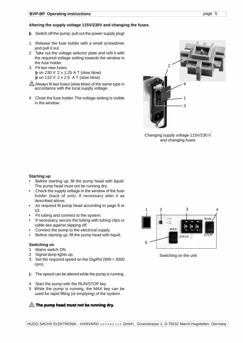
Changing supply voltage 115V/230 Vand changing fuses
Altering the supply voltage 115V/230V and changing the fuses.
þ Switch off the pump, pull out the power supply plug!
1 Release the fuse holder with a small screwdriverand pull it out.
2 Take out the voltage selector plate and refit it withthe required voltage setting towards the window inthe fuse holder.
3 Fit two new fuses:þ on 230 V: 2 x 1.25 A T (slow blow)þ on 115 V: 2 x 2.5 A T (slow blow)
Always fit two fuses (slow blow) of the same type inaccordance with the local supply voltage.
4 Close the fuse holder. The voltage setting is visiblein the window.
RUN
SPEED STOP
3
5
421
MAX
Switching on the unit
Starting up• Before starting up, fill the pump head with liquid.
The pump head must not be running dry.• Check the supply voltage in the window of the fuse
holder (back of unit). If necessary alter it asdescribed above.
• As required fit pump head according to page 8 or10.
• Fit tubing and connect to the system.• If necessary, secure the tubing with tubing clips or
cable ties against slipping off.• Connect the pump to the electrical supply.• Before starting up, fill the pump head with liquid.
Switching on1 Mains switch ON2 Signal lamp lights up.3 Set the required speed on the DigiPot (999 = 3000
rpm).
þ The speed can be altered while the pump is running.
4 Start the pump with the RUN/STOP key5 While the pump is running, the MAX key can be
used for rapid filling (or emptying) of the system.
The pump head mThe pump head mThe pump head mThe pump head mThe pump head m ust not be running drust not be running drust not be running drust not be running drust not be running dr yyyyy.....

HUGO SACHS ELEKTRONIK - HARVARD A P P A R A T U S GmbH, Gruenstrasse 1, D-79232 March-Hugstetten, Germany
BVP-BP Operating instructions page 6
Pin 10is connected to the stabilised +5 V DC supply voltageof the pump.
Pin 12 Overload StatusIn case the drive is overloaded, this pin (open collector)is connected to ground. Switch off the supply and allow the unit to cool down
for 2 minutes.
Pin 13If pin 13 is connected to pin 1 (ground), the speed canbe set with the speed selector on the operating panelinstead of by the signal on pin 5.
15-pin socket of analogue interfaceTTL contacts: RUN/STOP
Input: 0-5 V, 0-10 V, 0-20 mA, 4-20 mAOutput: 0-5 V DC, 0-6 kHz (speed)
A
B
S1
S2
Position of selectors S1 and S2 on theprinted circuit board
Analogue interface connector
Pin 1 GroundReference potential for all inputs and outputs.
Pin 2 RemoteSwitching over between manual operation and theanalogue interface. To activate the analogue interface,connect pin 2 to pin 1 (ground).
Pin 3 Start / StopThe pump starts up on connecting to pin 1 (ground).
Pin 5 Analogue InputExternal speed control (0-5 V, 0-10 V, 0-20 mA, 4-20mA). Selection by internal DIP switch (see underInternal Adjustments).
Pin 7 SupplyApprox. +36 V DC (unstabilised) is available (max. load1 A).
Pin 9 (Output) Motor SpeedThe factory setting is 0-5 V DC proportional to motorspeed 0-3000 rpm. As an alternative a frequency range0-6 kHz is available. Selection by internal slide switch(see below).
þ
Internal adjustmentsTo make the adjustments the casing has to be opened!
The casing mThe casing mThe casing mThe casing mThe casing m ust onlust onlust onlust onlust onl y be opened by be opened by be opened by be opened by be opened b y a pry a pry a pry a pry a pr operloperloperloperloperl yyyyyqualified perqualified perqualified perqualified perqualified per son!son!son!son!son!
Live parts inside the casing may remain live for sometime after the power supply plug has been pulled out.
Opening the casing (taking off the top metalcasing):þ Check before opening that the pump has been
disconnected from the electrical supply.To remove the metal casing, four screws (2 each rightand left) have to be unscrewed. Switches S1 and S2are then accessible.Note: during removal and re-assembly be careful notto damage the yellow-green ground wire to the casing!
DIP selector S2:This selector determines the form of external speedcontrol (pin 5).Settings selector S2 (DIP switches)
Slide switch S1:This switch affects pin 9, OUT
Position AAAAA: 0-5 V DC (normal setting)Position BBBBB: 0-6 kHz
* Normal setting when shipped from the factory

HUGO SACHS ELEKTRONIK - HARVARD A P P A R A T U S GmbH, Gruenstrasse 1, D-79232 March-Hugstetten, Germany
BVP-BP Operating instructions page 7
Output(capped)
Pump head BP-80
Inlet(capped)
Outlet
Inlet
Pump head BP-80, section
rotatingcones
Magnet ring Ball bearing
Centrifugal pump headsThe pump heads described below are speciallydesigned for pumping blood or erythrocytesuspensions. The heads BP-50 and BP-80 (Medtronic)can be fitted directly on to the holder of the pump drive,while Type SP-45 (Terumo) requires an adapter (SP-03) for operation.
NOTE: the information given below refers only to thespecial application of the heads in conjunction withthe BVP-BP drive. It does not replace the OperatingInstructions supplied with these heads.
The pump heads are hermetically sealed, there is nodrive shaft taken to the outside. The drive is transmittedthrough a magnetic coupling. A ring-shaped perma-nent magnet is located inside the head which is coupledto a similar magnet of the pump drive. Rotation of thedrive is transmitted to the pump rotor through theattraction force of the magnets.
Pump head BP-50 and BP-80The pump heads BP-50 and BP-80 (manufacturer:Medtronic) are specially designed for pumping bloodor erythrocyte suspensions. The BP-50 differs fromthe BP-80 by having a filling volume of 50 ml comparedwith 80 ml, and also by a lower throughput. Thediameter of the connections is also chosen suitablefor the flow rate: BP-50 6.4 mm, BP-80 9.5 mm.
A pump head BP-80 is shown alongside at the top.Details and pumping function can be seen from thesectional drawing below. The drive fitted with the pumphead is illustrated on the next page.
The cone-shaped vanes mounted above each othercan rotate about a central bearing and aremechanically coupled to the magnet ring. Rotation ofthe rotor causes the liquid inside the head to rotatethrough surface friction and to be forced outward bythe resulting centrifugal force towards the outletconnection. The resulting pressure-flow diagram isshown in Diagram 1 plotted against rotational speed.
Baseplate

HUGO SACHS ELEKTRONIK - HARVARD A P P A R A T U S GmbH, Gruenstrasse 1, D-79232 March-Hugstetten, Germany
BVP-BP Operating instructions page 8
Pumpe head
Magnet box
BVP-BP fitted with pump head BP-80
Diagram 1 : Output with pump head BP-80 plotted againstpump speed setting
0
2
4
6
8
10
12
400 500 600 700 800 900 1000
BVP-BPwith BP-80
File:perf_sys.wb3,diagr.8, Messg. 03.05.00
St
30 50
70100
150200 250 300
Parameter= pressure (30...300 mmHg)
Pump speed, DigiPot settings
Flo
w [
l/min
]
Output characteristic of a BP-80
Diagram 1 shows the flow-pressure characteristic ofthe combination BVP-BP with pump head BP-80 atvarying speed settings. At each speed a particularpressure was produced by squeezing the tubing andthe flow was measured. Normal tap water was usedas liquid during the measurement.
The pressure-flow diagram shows that there is no exactlinear relationship between speed and flow or pressure.
NOTE: the pressure/flow values which can be readfrom Diagram 1 must be taken only as average valuesand cannot not be guaranteed!
Pulsation: the pump head BP-80 (as well as thesimilarly designed but smaller BP-50) produces nopulsations in the flow of the liquid output!
Fitting and removing the BP-80
When fitting or removing the pump head the drive unitmust be switched off!
The baseplate of the pump head is inserted from aboveinto the slot between magnet box and pressure plate,and pushed down up to the stop. The head must thenbe rotated so that the locking pin engages with one ofthe recesses in the rim. The tubing connection for theoutlet should point to the right (as shown in theillustration alongside) so that the pump head can bevented when assembled (escape of trapped air).
To remove the head, tilt it slightly forward and then pullit upwards out of the holder.
Pressure plate, spring-loadet
Locking pin

HUGO SACHS ELEKTRONIK - HARVARD A P P A R A T U S GmbH, Gruenstrasse 1, D-79232 March-Hugstetten, Germany
BVP-BP Operating instructions page 9
Pump head SP-45
InletOutlet
0
2
4
6
8
10
12
14
16
18
300 400 500 600 700 800 900 1000
BVP-BPwith SP-45
File: perf_sys.wb3diagr.11 Messung 29.05.00
30
5070 100 200 300 400
Parameter = pressure (30...400mmHg)
Flo
w [
l/min
]
Diagram 2 : Output with pump head SP-45 plotted againstpump speed setting
Pump head SP-45
The pump head SP-45 (manufacturer: Terumo) isspecially designed for pumping blood or erythrocytesuspensions. Operation of the head with the BVP-BPdrive requires the use of the adapter SP-03.
A pump head SP-45 is shown alongside at the top.The drive fitted with the pump head is illustrated onthe next page.
The function of the head differs slightly from that theTypes BP-50/80 described before. The rotor does notconsist of several rotating conical vanes but of a flatrotating disc which carries 6 ribs. The ribs have aspecial shape so that very little turbulence is producedduring pumping.
The rotor disc rotates about a central bearing and iscoupled mechanically to the magnet ring. As the rotorrotates, the liquid inside the head is carried along bythe ribs and also made to rotate. The centrifugal forceproduced pushes the liquid to the outside towards theoutlet connection. The resulting pressure-flow diagramis shown in Diagram 2 plotted against rotational speedsetting.
Output characteristic of SP-45
Diagram 2 shows the flow-pressure characteristic ofthe combination BVP-BP with pump head SP-45 atvarying speed settings. At each speed a particularpressure was produced by squeezing the tubing andthe flow was measured. Normal tap water was usedas liquid for the measurement.
The diagram shows that there is not exact linearrelationship between speed and flow or pressure.
NOTE: the pressure/flow values which can be readfrom Diagram 2 must be taken only as average valuesand cannot not be guaranteed!
Pulsation: the pump head SP-45 produces slightpulsations during pumping which are evidently causedby the ribs on the rotor. The pulsation rate depends onthe rotor speed. At the maximum speed setting of 3000rpm the pulsation has a frequency of 300 Hz.
Pump speed, DigiPot settings
HUGO SACHS ELEKTRONIK - HARVARD A P P A R A T U S GmbH, Gruenstrasse 1, D-79232 March-Hugstetten, Germany
BVP-BP Operating instructions page 10
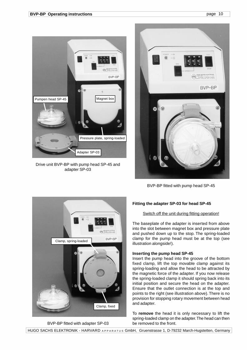
BVP-BP fitted with pump head SP-45
Clamp, spring-loaded
BVP-BP fitted with adapter SP-03
Adapter SP-03
Magnet box
Drive unit BVP-BP with pump head SP-45 andadapter SP-03
Pumpen head SP-45
Pressure plate, spring-loaded
Clamp, fixed
Fitting the adapter SP-03 for head SP-45
Switch off the unit during fitting operation!
The baseplate of the adapter is inserted from aboveinto the slot between magnet box and pressure plateand pushed down up to the stop. The spring-loadedclamp for the pump head must be at the top (seeillustration alongside!).
Inserting the pump head SP-45Insert the pump head into the groove of the bottomfixed clamp, lift the top movable clamp against itsspring-loading and allow the head to be attracted bythe magnetic force of the adapter. If you now releasethe spring-loaded clamp it should spring back into itsinitial position and secure the head on the adapter.Ensure that the outlet connection is at the top andpoints to the right (see illustration above). There is noprovision for stopping rotary movement between headand adapter.
To remove the head it is only necessary to lift thespring-loaded clamp on the adapter. The head can thenbe removed to the front.

HUGO SACHS ELEKTRONIK - HARVARD A P P A R A T U S GmbH, Gruenstrasse 1, D-79232 March-Hugstetten, Germany
BVP-BP Operating instructions page 11
Operating notes
Before switch-onEnsure that the pump head is filled with the liquid tobe pumped before you switch on. Operating the pumphead dry may damage the rotor bearing.
Pumping against pressureThe maximum flow rate depends on the back pressureand on the type of pump head used (see Diagrams 1and 2).
Speed settingIn order to keep haemolysis low you should not set ahigher speed than is necessary. Do not artificiallyincrease the flow resistance (squeezing the tubing) inorder to achieve a certain flow rate.
Faulty operationAs described above, the coupling of the drive to thepump rotor takes place through the attraction betweenthe magnets. The coupling force is sufficient for allnormal operations as long as the coupling does notbecome „disengaged“, e.g. through a sudden startingof the drive motor. The coupling can also becomedisengaged by careless handling of the tubing so thatthe pump head (or adapter) briefly does not lie properlyagainst the magnet box of the drive. If drive and pumphead have become „out of step“ this becomes evidentby a loud rattling or whirring noise.In this case switch off the drive briefly, allow it to cometo rest, and switch it on again.
Before switching off the pumpWhen stopping the pump drive it is possible thatthe liquid flows back if a non-return valve is not fittedon the outlet side!
Stopping the pumpIf the pump will be out of use for some time it is essen-tial to clean the pump head thoroughly (see under„Cleaning“).
RepairsFor repairs please send the faulty BVP-BP drive backto your supplier.Please state fault, purchase date, serial number andtype.
SparesFor repairs outside the warranty period you can contactyour supplier to obtain spare parts, list of items, wiringdiagrams. Please state fault, purchase date, serialnumber and type.
Maintenance and cleaningThe drive does not require any special maintenance.Any dirt on the casing should be removed immediately.A cloth moistened with water should be used forcleaning. With strongly adhering dirt you can add alittle cleaning solution (domestic detergent) to thewater.
WARNING:• Before starting any cleaning operation pull out the
power supply plug• Do not allow any liquid to pass into the casing
We recommend thorough cleaning of the pump headafter each application:• first wash out with normal tap water• with proteins in the liquid, wash again with acetic
acid (5%)• use distilled water for a final rinse.
The pump heads have to be considered as consumableitems with a limited life. Especially the internal seal(„Simmerring“ seal) of the rotor bearing is endangeredif• the pump head is operated dry, or• unsuitable cleaning agents are used, or• the cleaning agent is left inside the head for too
long.
If the pump is being used as intended and with thenecessary care, only the moving parts are subjectedto a certain amount of wear.
Technical dataDrive motor type: DC motor
Speed range: 60 - 3000 rpm= 50 rev/sec, adjustable in0.1% steps
Flow rate and pressure: depending on pump headExternal control: via analogue interface (see
page 6)Supply: 115 V (50/60 Hz) or 230 V
(50/60 Hz)Fuses: 2 x 2.5 A T (slow blow) at
115 V or 2 x 1.25 A T (slowblow) at 230 V
Power: 150 W max.Protection: IP 30
Operating conditions: normal laboratoryenvironment temperature+5 to +40°C rel. humidity80% max.
Dimensions (drive): DxWxH 220x155x260 mmWeight: 5.7 kg
CE conformity: approved to EN 50081-1/EN 50082-2/EN 61010-1

HUGO SACHS ELEKTRONIK - HARVARD A P P A R A T U S GmbH, Gruenstrasse 1, D-79232 March-Hugstetten, Germany
BVP-BP Operating instructions page 12
Reply formPlease take a few minutes of your time in order to write to us on any difficulties in understanding the OperatingInstructions or in the use of the apparatus. With your feedback you will help to improve our products and thesystem documentation and make them more user-friendly.Please tell us
where you have found mistakes,
where the arrangement was not clear and what you did not understand,
and where you would like to see improvements.
Many thanks for your kind assistance.Yours HUGO SACHS ELEKTRONIK - HARVARD APPARATUS GmbH.
☞
☞
☞
Your name
Organisation
Street
Town
Phone/Fax
Please send this sheet or a copy to:
Hugo Sachs Elektronik - HARVARD APPARATUS GmbH, Gruenstr. 1, D-79232 March-Hugstetten, GermanyFax. (int. + 49) 7665-9200-90

HUGO SACHS ELEKTRONIK - HARVARD A P P A R A T U S GmbH, Gruenstrasse 1, D-79232 March-Hugstetten, Germany
BVP-BP Operating instructions page 13
Index
A
acetic acid (5%) ... 11adapter SP-03 ... 9, 10Analogue interface ... 4, 6application range ... 2
B
blood, pumping ... 7, 9BP-50 ... 7, 8BP-80 ... 7, 8
C
cable, mains supply ... 4casing, opening the ... 6centrifugal force ... 7, 9circuit board ... 6claims ... 3clamp, fixed ... 10clamp, spring loaded ... 10Cleaning ... 11cones ... 7connections ... 7coupling force ... 11
D
Diagram, pressure flow ... 9Diagram, pressure-flow ... 8DigiPot ... 4, 5DIP switch ... 6disc, rotating ... 9distilled water ... 11
E
earth contact, protective ... 4emptying, rapid ... 5erythrocyte suspension ... 7, 9
F
Faulty operation ... 11filling, rapid ... 4, 5Fitting the adapter ... 10Fitting the head ... 8friction, surface ... 7fuse holder ... 4, 5fuses ... 5
G
GLP ... 2
H
haemolysis ... 11hazardous areas ... 3
I
internal adjustments ... 6
L
locking pin ... 8
M
magnet ... 2, 3, 7, 9, 10magnet box ... 8, 10magnetic field ... 3Mains switch ... 4, 5maintenance ... 11manufacturer`s details ... 2MAX key ... 4, 5medical applications ... 2Medtronic ... 2, 7motor speed ... 6
N
non-return valve ... 11
O
operating notes ... 11output of overload ... 6Overload ... 6
P
Power supply socket ... 4Pressure plate ... 8, 10pressure-flow diagram ... 8, 9proteins in liquid ... 11Pulsation ... 8, 9Pump ... 8, 9Pump head BP-50 ... 7Pump head BP-80 ... 7pump head BP-80 ... 8pump head SP-45 ... 9, 10pump rotor ... 7pumping against pressure ... 11pumping blood ... 7, 9
R
repairs ... 2, 11ribs on pump rotor ... 9risks, residual ... 3
S
safety precautions ... 2socket, 15-pin ... 6SP-03 ... 10SP-45 ... 9, 10Spares ... 11speed control ... 6speed, motor OUT ... 6speed setting ... 4, 5, 11supply ... 6supply voltage, altering the ... 5surface friction ... 7switching on ... 5
T
Terumo ... 2, 7, 9turbulence ... 9
V
valve, non return ... 11voltage selector ... 4, 5voltage selector indication ... 4voltage setting ... 5
W
WARNING ... 3Warning note ... 3wash ... 11window (115/230 V) ... 4, 5