bx-b31 - ram meter inc. · 2019-08-09 · iso gnd gnd +15 v dc iso gnd ntc emi filter isolated...
TRANSCRIPT
Texmate, Inc. Tel. (760) 598-9899 • www.texmate.com Page 17/10/03 BX-B31 Data Sheet (BX3)
LYNX
LYNX FAMILY
General Features
Specifications
Case Dimensions . . . . . . . . . . . . . . . . . . . . . . . . . . . . . . . .7
Component Layout . . . . . . . . . . . . . . . . . . . . . . . . . . . . . . .3
Connector Pinouts . . . . . . . . . . . . . . . . . . . . . . . . . . . . . . . .2
Connectors . . . . . . . . . . . . . . . . . . . . . . . . . . . . . . . . . . . . .2
Functional Diagram . . . . . . . . . . . . . . . . . . . . . . . . . . . . . . .2
General Features . . . . . . . . . . . . . . . . . . . . . . . . . . . . . . . .1
I-Series Input Signal Conditioning Modules . . . . . . . . . . . .4-5
Input Module Calibration Procedures . . . . . . . . . . . . . . . .6-7
Input Module Compatibility . . . . . . . . . . . . . . . . . . . . . . . . .1
Input Module Component Glossary . . . . . . . . . . . . . . . . . . .6
Ordering Information . . . . . . . . . . . . . . . . . . . . . . . . . . . . . .8
Pin Descriptions . . . . . . . . . . . . . . . . . . . . . . . . . . . . . . . . .2
Specifications . . . . . . . . . . . . . . . . . . . . . . . . . . . . . . . . . . .1
Index
Input Module Compatibility
Input Specs: ..............Depends on input signal conditioner
A/D Converter: ..........31 step flash converter
Accuracy: ..................±(0.05% of reading + 3 counts)
Temp. Coeff.: ............100 ppm/°C (Typical)
Warm up time: ..........2 minutes
Display:......................Thirty-one 0.2” x 0.06” (5.08 x 1.52mm)
LED segments. Red display (std), green
(opt) or amber (opt)
Positive Overrange:..All segments flash.
Negative Overrange:..Zero segment flashes
Power Supply: ..........AC/DC Auto sensing wide range supply
PS1 (std) ................85-265 VAC / 95-370 VDC @ 2.5W
PS2 ........................15-48 VAC / 10-72 VDC @ 2.5W
Operating Temp.: ......0 to 60° C
Storage Temp: ..........-20° C to +70° C
Relative Humidity: ....95% (non condensing)
Case Dimensions: ....1/16 DIN, Bezel: 96x24mm(3.78”x0.95”)
Depth behind bezel 122.2 mm (4.83")
Plus 12.7mm (0.5”) for Right-angled
connector.
Weight: ......................198 gms (7 oz)
255 gms (9 oz) when packed
LYNX FAMILY: More than 33 different Plug-in
I-Series Input Signal Conditioners are approved for
Texmate’s Lynx Family of meters. As shown on
pages 4 to 5.
See www.texmate.com for an up to date listing.
• 31 segment AC/DC powered modular compact bargraph.
• 1/16 DIN (96 x 24mm ) case easily mounts in thin or thick
panels (up to 2”).
• Red (std), green (optional) or amber (optional) colors.
• Vertical or horizontal formats.
• External transmitters or signal conditioners can be eliminated
by directly connecting the sensor to more than 33 I-Series
Plug-in Input Signal Conditioning Modules that include:
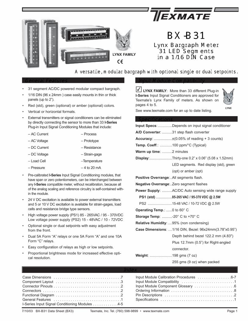
A versatile, modular bargraph with optional single or dual setpoints.
BX-B31Lynx Bargraph Meter31 LED Segmentsin a 1/16 DIN Case
• Pre-calibrated I-Series Input Signal Conditioning modules, that
have span or zero potentiometers, can be interchanged between
any I-Series compatible meter, without recalibration, because all
of the analog scaling and reference circuitry is self-contained with-
in the module.
• 24 V DC excitation is available to power external transmitters
and 5 or 10 V DC excitation is available for strain-gages, load
cells and resistance bridge type sensors.
• High voltage power supply (PS1) 85 - 265VAC / 95 - 370VDC
Low voltage power supply (PS2) 15 - 48VAC / 10 - 72VDC
• Optional single or dual setpoints with easy adjustment
from the front.
• Dual 5A Form “A” relays or one 5A Form “A” and one 10A
Form “C” relays.
• Easy configuration of relays as high or low setpoints.
• Proportional brightness mode for increased effective opti-
cal resolution.
– AC Current
– AC Voltage
– DC Current
– DC Voltage
– Load Cell
– Pressure
– Process
– Prototype
– Resistance
– Strain-gage
–Temperature
– 4 to 20 mA

Texmate, Inc. Tel. (760) 598-9899 • www.texmate.comPage 2 7/10/03 BX-B31 Data Sheet (BX3)
Functional Diagram
Pins 1 to 6 - Input Module: See the individual pin out of the input sig-nal conditioning module selected. Usually Pin 1 is the Signal Input Highpin and Pin 3 is the Signal Input Low pin. All calibration and scalingfunctions are performed on the individual input signal conditioner mod-ule. See pages 6 and 7.
Pin 8 - Common of 10 Amp Form C or 5 Amp Form A SP1 Relay.
Pin 9 - Normally Closed Contact of 10 Amp Form C SP1 Relay.
Pin 10 - Normally Open Contact of 10 Amp Form C or 5 Amp Form ASP1 Relay.
Pin 11 & Pin 12- Normally Open Contacts of 5 Amp Form A SP2Relay.
Pin 14 & Pin 15 - AC/DC Power Input: These pins are the power pinsof the meter and they only accept a special polarized screw terminalplug that can not be inserted into any other input socket. The stan-dard meter has a auto sensing AC/DC power supply that operatesfrom 85-265 VAC/95-370 VDC (PS1 Std). An optional isolated lowvoltage power supply that operates from 15-48 VAC/10-72 VDC (PS2) isalso available.
Connector Pinouts
Pin DescriptionsPin Socket Pin Socket
Right-angled
Screw Terminal Plug
Input Power
Screw Terminal Plug
Connectors
15 to 48 VAC10 to 72 VDC
85 to 265 VAC95 to 370 VDC
NC
1
NO
1
CO
M 2
NO
2
981 2 3 4 5 6 10 11 12 14 15
AC Neutral– DC
AC Line+ DC
See Lynx Family Input
Signal Conditioning Modules
PS2
PS1
CO
M 1
This meter comes standard with screw terminal plug connections.Top Catches
TO REMOVE REAR COVER
Release From Bottom
This meter uses plug-in type screw terminal connectors for all inputand output connections. The power supply connections (pins 14and 15) have a unique plug and socket outline to prevent cross con-nection. The main board uses standard right-angled connectors.
I-Series Input SignalConditioning Module
NO 2
NC 1
NO 1
9
10
11
12
14
15
2
3
5
1
4
1
2
3
4
5
6
7
8
9
10
Input and output
pins vary for
different modules.
Please see the
specific module
data sheet for
details.
1.25 V Bandgap
Reference
BX-B31 Functional Diagram with one 10 Amp Form C
and one 5 Amp Form A Relay
AC Neutral, – DC
AC Line, + DC
AC/DC Power Input
1 3 5 7
2 4 6 8
9
10
Socket for Input SignalConditioning Module
Input Hi
Input Lo
+5VDC
-5VDC
+24VDC
Analog Common
System Ground
24 V Return
Amplifier
Circuit
Proportional
Brightness
Circuit
Proportional
Brightness PotRelay Activation
Selection Header
10K
Comparators
and LED
1 to 10
Driver Circuit
Comparators
and LED
11 to 20
Driver Circuit
Comparators
and LED
21 to 30
Driver Circuit
Com 1 8
SP1 RelayDriver Circuit
SP2 RelayDriver Circuit
BX-B31 with no setpoints
BX-B31 with 1 setpoint
BX-B31 with 2 setpoints
5ASP2
+5 V
+5 V
10A SP1
+5 V
5ASP2
8NO 1
9
NO 1
NO 2
10
11
12
with two 5 Amp Form A relays
14
15
5A
+5 V
SP1
AC Neutral, – DC
AC Line, + DC
AC/DC Power Input
Low 1
High 1
Low 2
High 2
NTC
EMI Filter
Isolated Switching
Supply-5 V DC
+5 V DC
+24 V DC
ISOGND
GND
+15 V DC
ISOGND
NTC
EMI Filter
Isolated Switching
Supply-5 V DC
+5 V DC
+24 V DC
ISOGND
GND
+15 V DC
ISOGND
FRONT OF METER WITH BEZEL AND FILTER REMOVED
To adjust the setpoint on the BX-B31 with relays, remove thefront bezel and faceplates. Use needlenose pliers to removeand reposition the setpoint jumper clips.
For Setpoint #1: Insert the jumper clip between Row #1 andRow #2, directly below the LED that you wish to activate.
For Setpoint #2: Insert the jumper clip between Row #2 andRow #3, directly below the LED that you wish to activate.
LEDsRow 1
Row 2
Row 3
Custom Face Plates
Changing the Setpoints From the Front of the Meter
Low 1
High 1
Low 2
High 2 Relay Activation Select HeaderSelect High to energize the relay when the setpoint is
exceeded. Select Low to energize the relay when the
display is below the setpoint.
The Proportional Brightness Potentiometer superimposes a proportion-
al brightness band to the leading edge of the bargraph which creates
Proportional Brightness Band Potentiometer
WARNING: AC and DC input signals and power
supply voltages can be hazardous. Do Not connect
live wires to screw terminal plugs, and do not insert, remove or
handle screw terminal plugs with live wires connected.
!
Texmate Produces Thousands of CustomOEM Face Plates
Have Texmate Design and Build a Custom Face Plateto Suit your Next project!
• Custom face plates have a non-recurring artworkcharge. A serial number is then assigned to eachartwork, to facilitate re-ordering.
• Small Run or One-Off custom face plates incur an installation charge,and are generally printed on a special plastic film, which is then lami-nated to custom faceplate blanks as required.
• Large Run (250 pieces min): custom face plates are production silkscreened, issued a part number, and held in stock for free installationas required by customer orders.
• OEMs may also order Custom Meter Labels, Box Labels CustomData Sheets and Instruction Manuals.
the optical appearance of a pointed arrow . This feature produces a
display of infinite resolution. The position of the signal in relation to any
two adjacent segments and the scale on the faceplate can be accu-
rately ascertained to within 1%. When the amplitude of the proportion-
al band is adjusted counterclockwise to zero, the smooth proportional
advance of the display will be replaced by a step by step movement as
each bar is either turned full on or full off.

Texmate, Inc. Tel. (760) 598-9899 • www.texmate.com Page 37/10/03 BX-B31 Data Sheet (BX3)
Component Layout
Cu
sto
m2
00
V2
0V
2V
ON
OF
F
24V Exc
< Increase Span Decrease >
Typical input signal conditioner shown
Low Voltage
Transformer is
Colored Black
LV
Cu
sto
m2
00
V2
0V
2V
ON
OF
F
24V Exc
< Increase Span Decrease >
Typical input signal conditioner shown
High Voltage
Transformer is
Colored Grey
HV
BX-B31-XX-PS2 (Low Voltage)BX-B31-XX-PS1 (High Voltage)
Standard Face Plates and Scales
0 10 20 30 40 50 60 70 80 90 100
10x5
50
6x5
30
7.5x5
37.5
8x5
40
9x5
45
6x2x2
24
4x5x2
20
5x5x2
25
6x5
30
8x5
40
9x5
45
10x5
50
5x3x2
15
11010010001.5151501500
22020020002.5252502500
33030030004404004000
4.54545045005505005000
66060060007.5757507500
88080080009909009000
1.2 121201200
Div.0102030
50
80
100
7060
40
90
0
2
4
6
8
10
12
0
3
6
9
12
15
0
5
10
15
20
0
5
10
15
25
20
0
5
10
15
30
20
25
0
5
10
15
20
35
30
25
40
05101520
3540
3025
45
051015
25
40
50
3530
20
45
0
10
20
30
40
50
60
0
10
20
30
40
50
60
7075
0
10
20
30
40
70
60
50
80
010203040
7080
6050
90
• Unless otherwise specified, a standard 0-100 scaled face plate with white letters on a black background is provided with each meter.In those cases where a temperature modules is ordered, a 0-300 °F (white on black) face plate will be provided as standard.
• Alternatively a face plate with black letters on a white background or a blank, white or black face plate, may be ordered as a no charge substitute. For temperature applications there are also several different optional face plates that may be ordered as a no charge substitute. (See below).Customized face plates with special scaling can also be ordered.
0102030405060708090100
0102030405060708090100
0102030405060708090100
0
30
60
90
120
150
°C°F
0
50
100
150
300
200
250
0
30
60
90
120
150
°C°F0
50
100
150
300
200
250
0102030405060708090100
0 10 20 30 40 50 60 70 80 90 100
0 10 20 30 40 50 60 70 80 90 100
76-BXB3/BH standard
76-BXB3R/BH standard
76-BXB3R/WH optional
76-BXB3/WH optional 76-BXB3/WVoptional 76-BXB3/WXoptional76-BXB3/BVstandard 76-BXB3/BV2standard76-BXB3R/BV2standard 76-BXB3/WV1optional76-BXB3R/WV1optional76-BXB3/BXoptional76-BXB3R/WVoptional 76-BXB3R/WXoptional76-BXB3R/BVstandard 76-BXB3R/BXoptional
0 10 20 30 40 50 60 70 80 90 100
90 mm
(3.54")
18 mm(0.71")
0102030405060708090100
0102030405060708090100
Face plate scales and numbersare shown close to actual size
Optional no charge substitute faceplatesfor Temperature may be ordered scaled
0 to 300°F or 0 to 150°C,Vertical orHorizontal in Black or White background
See next page for clear self-adhesive caption sheets, each meter is shipped with standard or optional faceplates.

Texmate, Inc. Tel. (760) 598-9899 • www.texmate.comPage 4 7/10/03 BX-B31 Data Sheet (BX3)
I-Series Input Signal Conditioning Modules
IA04: AC Amps Scaled RMS, 1 Amp ACIA05: AC Amps Scaled RMS, 5 Amp AC
HIRANGE
AC AMPS
HI
LO
LO
< In
cre
ase
Sp
an
De
cre
ase
>
LEOPARD
LYNX
TIGER1A
SecondaryCT
Prim
ary
A
C C
urr
en
t
Fully User Scalable
065D
ACV-LO
IA02: AC Volts Scaled RMS, 200mV/2V/20V AC
20V
0.2V
2VLEOPARD
LYNX
TIGER
140A
IA01: AC Volts Scaled RMS, 200/600V AC
L N
200V
600V
LEOPARD
LYNX
TIGER
123A
IA09: AC Amps True RMS, 1 Amp ACIA11: AC Amps True RMS, 5 Amp AC
LEOPARD
LYNX
TIGER1A/5A
SecondaryCT
Prim
ary
A
C C
urr
en
t
Fully User Scalable
++ +
AC AMPS RMS
1 A
Sh
un
t
301B
IA08: AC Milliamps True RMS, 2/20/200mA AC
LEOPARD
LYNX
TIGER
370B
2 / 20 / 200 mA
RMS
PIN 1
PIN 2
IA07: AC Volts True RMS, 200mV/2V/20V AC
LEOPARD
LYNX
TIGER
369B
2 V / 20 V RMS
PIN 1
PIN 2
SPAN
300 V
600 V
IA06: AC Volts True RMS, 300/600V AC
LEOPARD
LYNX
TIGER
AC V RMS HI
300C
ID01: DC Volts, 2/20/200V/Custom w/24V DC Exc
Cu
sto
m2
00
V2
0V
2V
ON
OF
F
24V Exc
24VExc
< Increase Span Decrease >
LEOPARDIP07
LYNX
TIGERIP07
090D
IA12: AC Millivolt RMS Sigma Delta
371A
ACmV RMS
HI
LO
PIN 1
PIN 2
LEOPARD
LYNX
TIGER
IA10 AC Millivolts, Scaled RMS, 100mV AC
AC
I
HIRANGE
ACmV
ACmVHI
LO
LO
< In
cre
ase
Sp
an
De
cre
ase
>
LEOPARD
LYNX
TIGER
Fully User Scalable
285A
20
01
00
50
20
ID02: DC Millivolts, 20/50/100/200mV DC w/24V DC Exc
24VExc
ON
OF
F
24V EXC DCmV
< Increase Span Decrease >
LEOPARD
LYNX
TIGER
142A
IA03: AC Milliamps Scaled RMS, 2/20/200mA AC
AC mA
AC mA
200mA
20mA
2mA
HI
LOLEOPARD
LYNX
TIGER
280A
Many additional input modules are available and others are constantly being developed. Check with your local distributor orwww.texmate.com for updated information.
Precalibrated I-Series input modules, that have span or zero potentiometers, can be interchanged between any I-Series com-patible meter, without recalibration, because all of the analog scaling and reference circuitry is self-contained within the mod-ule. Where appropriate, all the standard ranges shown are designed to be header selectable by the user, and Texmate's unique
SPAN ADJUST Header facilitates scaling to almost any requiredengineering unit. See Input Module Component Glossary andCalibration on pages 6 and 8.
Unless otherwise specified Texmate will ship all modules precali-brated with factory preselected ranges and/or scalings as shown inBOLD type. Other precalibrated standard ranges or custom rangesmay be ordered. Factory installed custom scaling and other customoptions are also available (see Ordering Information, SpecialOptions on last page).ALL MODELS
Symbols Indicate Module Compatibility Within Meter Families
SOME MODELS MODEL SPECIFIC
TIGER Family
LEOPARD Family
LYNX Family
TIGER Family
LEOPARD Family
LYNX Family
TIGER Family
LEOPARD Family
LYNX Family
AJK mVαβφΩ∆µϑγ
%∠
ACAhcddBDCFTHPHzKgkAL3m3W°C°F°K
EbkJkVkWmlNLPaPFpHsint/hyd3µAµSµVµΩ
BtubarcalcmFT3lbsIN2kg/mAmSmVNmozRH1/hµm
barscal15cm-1cm2cm3dm3H2OkPa /s /h /mlb/hMWminmmSm3
CFHCFMCFSCOSCPHCPMCPSDCAFPHFPMFPSGALGMPGPHGPMGPS
BHPIPSIPHKg/hKPHKPMKPSkWHIb/ftIb/inLPHLPMLPSm3/hm3/mm3/S
LowHighMGDMldMPHMPSN/m2ORPPPHPPMPPSRPHRPSphipsiX10
inch/Kcalkg/hrkVARkW/sRPMMPMM3/hrUpmVACVarsVDCw/m2YPMYPSµPa
CosØFEETHoldKm3/hMWHmWsmbarml/m3mm/sPeakPORTSTRBTARETONSX100%KW
AMPSGALSINHgm/minm/secNm3/hOhmsPSIAPSIDPSIGPSIRSCFMTORRU/minx10kNX1000
BBL/HRBBL/MINDEG/MINFT H2OIn.H2OKg/cm2KNOTSkg/secMvarsmmH2OmmHgVOLTS%LOAD%OPEN
(L450)
AC MilliamperesBattery VoltageBackup VoltageDisplacementDC Amps to GroundDC MicroamperesDC MilliamperesGALLONS / MINUTEGENERATOR AMPSLBS PER GALLONLOAD LIMIT PERCENTMANIFOLD PRESSUREMILL LOAD AMPSMOTOR LOAD AMPSPercent HorsepowerOXYGEN PERCENTTEMPERATURE °CTEMPERATURE °FMotor Load PercentLEFT RIGHTFRONT REARFORWARD REVERSETOP BOTTOM
AHEADALARMBOILERCyclesDepthHEATERHeightHertzHoursINCHESInputPORT PUMPPresetResetSHAFTSPEEDSetupTABLETotalVALVEValleyWATTS
AC VarsAC VoltsAC WattsBEARINGCOOLANTDC VoltsDC WattsDegreesENGINEEXHAUSTHumidityMETERSOutputPercentProgramPoundsPulsesRUDDERSPINDLESQ ROOTSet PointTHRUSTTURBINE
AC AmperesAC KilovarsAC KilovoltsAIR FLOWBBLS/HOURBFM AMPSBHP x 100BLOWERDC CurrentDew PointDegrees CDegrees FDegrees KDegrees RFPM X 10FrequencyFUEL FLOWGALLONSIN. WATERLEVEL FT.LBS X 100POSITIONTONS X 10
AC KilowattsAC MillivoltsBPH X 1000CFH x 1000DC AmperesDC KilovoltsDC KilowattsDC MillivoltsFPM X 100FPM X 1000GPM X 1000HORSEPOWERINCHES WCINCHES H2OKILOWATTSLBS X 1000MEGAWATTSPower FactorPhase AngleRPM X 100STARBOARDTANK LEVELVAC MM HG
AIR PRESSUREAC KiloamperesAC MegavarsAC MegawattsAC Watts/VarsCENTIMETERSDC KiloamperesFD FAN AMPSIN. H2O PRESSLBS/MINUTELEVEL INCHESLEVEL GALLONSLEVEL PERCENTMILLIMETERSPercent CurrentPercent LoadPERCENT OPENRATE of TURNSTEAM TEMP °FTONS / HOUROIL PRESSUREWATER LEVEL1000 LBS/HOUR
Standard Caption Sheets (white or black lettering for do-it-yourself customizing)Clear self-adhesive caption sheets with white or black lettering are provided for each meter shipped with a standard or optional faceplate.

Texmate, Inc. Tel. (760) 598-9899 • www.texmate.com Page 57/10/03 BX-B31 Data Sheet (BX3)
I-Series Input Signal Conditioning Modules ContinuedID03: DC Milliamps, 2/20/200mA DC w/24V DC Exc
2m
A2
0m
A2
00
mA
ON
OF
F
24V Exc
24VExc
DCmA
< Increase Span Decrease >
LEOPARDIP07
LYNX
TIGERIP07
141E
IP01: Process Loop, 4-20mAIP02: Process Loop, 4-20mA with 24VDC EXC
24VExternalLoop Supply
Common
Offset
0
+
_
Other devices can beadded to the loop.
< Decrease Zero Increase >
< Decrease Span Increase >
Ra
ng
e
HI
LO
OFF
ON
24V
EX
C
LEOPARD
LYNX
TIGER
Fully User Scalable
PIN 2
+ _
091E
IS06: Pressure/Load Cell Ext Exc., 20/2mV/V, 4-wire
5 V or 10 V External Power Supply Drift is Ratiometrically Compensated by Module
For multiple pressure transducers
– +
2H
I
LO
RA
NG
EmV/V
20
10
V
5V
EX
T
EX
C
PRESSURE
LEOPARDIS04
LYNX
TIGERIS04
244C
IP03: Process Input, 1-5V DC with Offset, 24V Exc
+24 V
+
_
1 to 5V Input Offset
0
+
_
< Decrease Zero Increase >
< Decrease Span Increase >
Ra
ng
e
HI
LO
OFF
ON
24V
EX
C
LEOPARDIPO7
LYNX
TIGERIP07
Fully User Scalable
PROCESS 1 to 5V DC
PIN 2Common1 to 5V
250Ω
4/20mA
091E
ID04: DC Amps, 5A DCID09: DC Amps, 1A DC
DC AMPS
LO RANGE HI
< In
crea
se S
pa
n D
ecre
ase
>
LEOPARD
LYNX
TIGER
Fully User Scalable
065D
0
+
_
ID05: DC Volts 2/20/200/Custom V DC with Offset and 24V Exc.
ON
OF
F
24V Exc
Cu
sto
m2
00
V2
0V
2V
< Increase Span Decrease >
Offs
et
24VExc
LEOPARDIP07
LYNX
TIGERIP07
090D
J/K THERMOCOUPLE
LINEARITY
ZERO
SPAN
T/C +
T/C –
IT06: Thermocouple, J Type (0-1400 ˚F)IT08: Thermocouple, J Type (0-760 ˚C)
LINEARISATION IS ANALOG
Conformity error to NIST tables (at 25°C)
J ±(2 ˚C + 1 digit) typical
J ±(4 ˚F + 1 digit) maximum
K ±(3 ˚C + 1 digit) typical
K ±(5 ˚F + 1 digit) maximum
LEOPARD
LYNX
TIGERIT01
271D
3
1
5
15
7
17
9
11
13
4
2
6
16
8
18
10
12
14
IPT1: Prototype Board for Custom Design
LEOPARD
LYNX
TIGER
195C
J/K THERMOCOUPLE
T/C +
T/C –
IT07: Thermocouple, K Type (0-1999 °F)IT09: Thermocouple, K Type (0-1260 °C)
LINEARISATION IS ANALOG
Conformity error to NIST tables (at 25°C)
J ±(2 °C + 1 digit) typical
J ±(4 °F + 1 digit) maximum
K ±(3°C + 1 digit) typical
K ±(5 °F + 1 digit) maximum
LEOPARD
LYNX
TIGERIT01
LINEARITY
ZERO
SPAN
272D
24VExc
ON
OF
F
24V Exc DCmA
ID07: DC Milliamps, 2/20/200mA DC with Offset and 24V Exc
2m
A2
0m
A2
00
mA
Offs
et
0
+_
< Increase Span Decrease >
LEOPARDIP07
LYNX
TIGERIP07
141E
IR02: 3 wire Potentiometer 1KΩ min (0-F.S.)
< Increase Span Decrease >
POTENTIOMETER
1KΩ Minimum1MΩ Maximum
100% Signal Span 1 K = 2000
LEOPARD
LYNX
TIGER
273A
Pt-100ΩRTD
4 w
ire
4 wire 3 wire
3 w
ire
LEADCOMP
LIN
RTD
IT03: RTD, 100Ω Pt. 2/ 3/4-wire (-200 to 800°C)IT04: RTD, 100Ω Pt. 2/ 3/4-wire (-200 to 1470°F)IT05: RTD, 100Ω Pt. 2/3/4-wire (-199.9 to 199.9°F)IT14: RTD, 100Ω Pt. 2/3/4-wire (-199.9 to 199.9°C)
Excitation is 1mA
Up to 50Ω resistance in each
lead can be compensated
Typical accuracy is±(0.3% + 1 digit)
LINEARISATION IS ANALOG
LEOPARD
LYNX
TIGERIT02
187C
IR03: Linear Potentiometer 1KΩ min
POTENTIOMETER
1KΩ Minimum
Digital ScalingInput
Exc
Gnd
1MΩ Maximum
273A
LEOPARD
LYNX
TIGER
IF02: Line Frequency
LEOPARD
LYNX
TIGERIF06
SPAN
ZEROFrequency to Voltage Conversion
60 to 500V AC
269D
IGYZ: Universal Direct Pressure (Absolute or Differential/Gage) See below for ordering code options
332D
ABSOLUTE / DIFFERENTIAL PRESSURE
LEOPARD
TIGER
LYNX
IS05: Pressure/Load Cell 20/2mV/V, 5/10V Exc 4-wire
Pressure Transduceror Load Cell 2
HI
LO
RA
NG
E
mV/V
20
10
V
5V
EX
T
EX
C
PRESSURE
LEOPARDIS02
LYNX
TIGERIS02
244C
IS04: Pressure/Load Cell Ext Exc., 20/2mV/V, 4/6–wire
220
mV
/V
10V
5V
4W
6W
EX
C
ExternalPower Supply 5 V or 10 V
For multiple pressure transducers
LEOPARD
TIGER
150A
Ordering Code Options for Direct Pressure (IGYX, IGYY & IGYZ)
I G For Single Channel IGYX withtwo digital inputs, the last digitof order code is always X.
For Universal Direct PressureIGYZ, the last digit of ordercode is always Z.
1 psi Absolute
Sensor RangeCH1
Order CodeCH2
Order Code
1 psi Differential
5 psi Absolute
5 psi Differential
15 psi Absolute
15 psi Differential
30 psi Absolute
30 psi Differential
100 psi Absolute
100 psi Differential
A
B
C
D
E
F
G
H
J
K
A
B
C
D
E
F
G
H
J
K

Texmate, Inc. Tel. (760) 598-9899 • www.texmate.comPage 6 7/10/03 BX-B31 Data Sheet (BX3)
Input Module Component Glossary
ZERO ADJUST HeaderWhen this header is provided, it works in conjunc-tion with the ZERO OFFSET RANGE Header, andexpands the ZERO pot’s offset capability into fiveequal negative steps or five equal positive steps.This enables virtually any degree of input signaloffset required to display any desired engineeringunit of measure.
ZERO OFFSET RANGE HeaderWhen provided, this three position header increas-es the ZERO pot’s capability to offset the input sig-nal, to ±25% of the digital display span. For exam-ple a Negative offset enables a 1 to 5V input todisplay 0 to full scale.The user can select negativeoffset, positive offset, or no offset (ZERO pot dis-abled for two step non-interactive span and offsetcalibration).
SPAN RANGE HeaderWhen this header is provided it works in conjunc-tion with the SPAN ADJUST Header by splitting itsadjustment range into a Hi and a Lo range. Thishas the effect of dividing the adjustment range ofthe SPAN pot into ten equal 10% steps across100% of the input Signal Span.
INPUT RANGE Header Range values are marked on the PCB.Typically twoto four positions are provided, which are selectedwith either a single or multiple jumper clip. Whenprovided, a custom range position is only functionalwhen the option has been factory installed.
Input and Output PinsOn most modules Pin 1 is the Signal High inputand Pin 3 is the Signal Low input.Typically Pin 2 isused for Excitation Voltage output.
24V DC Output HeaderOn some modules this header enables a 24V DC25mA (max) Excitation/Auxiliary output to be con-nected to Pin 2.
Note: I-Series modules with analog calibration and scaling capabilitycan be interchanged between any compatible meter without recalibra-tion. However, meters that also have software scaling and calibrationcapabilities such as meters in the Leopard and Tiger families or Lynx
Q-Series (Quickset programming), must have their software scaling setto unity gain.
Basic standard range calibration of direct readingmodules that utilize either Auto Zero or a ZERO pot,an INPUT RANGE Header and or a SPAN pot.1 If the module has an INPUT RANGE Header, reposition the jumper
clip to select the desired input signal range.
2. Apply a zero input or short the input pins. The display will auto zero,or if the module has a ZERO pot, it should be adjusted until the dis-play reads zero.
3 Apply a known input signal that is at least 20% of the full scale inputrange and adjust the SPAN pot until the display reads the exact inputvalue.The Lynx family of Q meters can accept negative signals also,and may be scaled for inputs from -50% to +100% of the rangeselected on the input signal conditioning module.
Wide range scaling, in engineering units not requir-ing offsets, with modules that utilize auto-zero or aZERO pot, a SPAN RANGE Header and or a SPANADJUST Header.
Input Module Calibration
LO RANGE HI RANGE
10%SPAN Pot % 10% 10% 10% 10%
10%Signal Span % 20% 30% 40% 50%
1
SPAN AdjustHeader position
Span Adjust Header Span Adjust Header
Span Range Header
2 3 4 5
10% 10% 10% 10% 10%
60% 70% 80% 90% 100%
1 2 3 4 5
< Decrease Span Increase >
1 2 3 4 5
< Decrease Span Increase >
1 2 3 4 5
EquivalentCircuit
Acts like a150 Turn
Potentiometer Low Range High RangeInput LO Input HI
HILO
< Increase Zero Decrease >
5 4 3 2 1
< Increase Zero Decrease >
54
3
21
SPAN
Turn Clockwise toIncrease Reading
To the Right Rear
HI
LO
24VExc
Offset
0—
+
0—
+
Custom
200V
20V
2V
ON
OFF
OFF
ON
24V
EX
C
< Increase Span Decrease >
5 4 3 2 1
< Increase Span Decrease >
5 4
3
2 1
Ra
ng
e
HI
LO
HI
LO
Zero Offset Range HeaderZero Adjust Header Zero Adjust Header
0 +–
–20%ZERO Pot % –20% –20% –20% –20%
NoOffset
NEGATIVE OFFSET POSITIVE OFFSET
≈ –75% of display spanOffset Range
+20% +20% +20% +20% +20%
≈ +50% of display span
5ZERO AdjustHeader position 4 3 2 1 1 2 3 4 5
75 Turn Potentiometer
– 0EquivalentCircuit
< Increase Zero Decrease >
5 4 3 2 1
< Decrease Zero Increase >
1 2 3 4 5
75 Turn Potentiometer
+0
Zero PotDisabled
ZERO
Turn Clockwise toIncrease Reading
To the Left Rear
SPAN Potentiometer (Pot)If provided, the 15 turn SPAN pot is always on theright side (as viewed from the rear of the meter).Typical adjustment is 20% of the input signal range.
15 Turn Potentiometer
≈ + 1000 Counts≈ – 1000 Counts– 0 +
20%SPAN Pot % 20% 20% 20% 20%
20%Signal Span % 40% 60% 80% 100%
1SPAN AdjustHeader position 2 3 4 5
< Decrease Span Increase >
1 2 3 4 5
Acts like 75 Turn 1 Megaohm PotentiometerInput LOInpHI
EquivalentCircuit
SPAN ADJUST HeaderThis unique five-position header expands theadjustment range of the SPAN pot into five equal20% steps, across 100% of the input Signal Span.Any input Signal Span can then be precisely scaleddown to provide any required Digital Display spanfrom 19999 counts to 0001 (one count).
ZERO Potentiometer (Pot)If provided, the ZERO pot is always to the left ofthe SPAN pot (as viewed from the rear of themeter). Typically it enables the input signal to beoffset ±5% of full scale (-1000 to +1000 counts).
Zero Offset Range Header
0 +–No
Offset
NEGATIVE OFFSETDecreases Digital Reading
POSITIVE OFFSETIncreases Digital Reading
15 Turn Potentiometer
– 0EquivalentCircuit
15 Turn Potentiometer
+0
Zero PotDisabled
≈ – 5000 CountsOffset Range
– 100% of OffsetZERO Pot%
≈ + 5000 Counts
+ 100% of Offset
WARNING: AC and DC input signals and power supply
voltages can be hazardous. Do Not insert, remove or handle
modules with live wires connected to any terminal plugs.!

Texmate, Inc. Tel. (760) 598-9899 • www.texmate.com Page 77/10/03 BX-B31 Data Sheet (BX3)
Case Dimensions
Input Module Calibration Procedures ContinuedThe second step is to set the ZERO ADJUST and or ZERO OFFSETRANGE Header to provide a positive or negative offset so that calibra-tion with the ZERO pot will offset the Display Span to produce therequired display reading.
Example B: Using a BX-B31 Bargraph meter.
Input signal 1 to 5 V to read zero to full scale.
Signal Span = 4 V, Display Span = 30 segments
1 If the module has an INPUT RANGE Header the 2 V position shouldbe selected.This will provide a display of 30 segments for an input of2 V which is (2 ÷ 4) = 50% of the examples 4 V signal span.To scaledown the Signal Span to 50% select the next higher 60% SignalSpan position on the SPAN ADJUST Header (position 3).
2 If the module is a Process Input 1-5 V DC type, select the (Hi Range)position on the SPAN RANGE Header and the 100% Signal Spanposition on the SPAN ADJUST Header (position 5, max increase).This will provide a display of 30 segments for an input of 4 V which is100% of the examples 4 V Signal Span.
3 Set the ZERO OFFSET RANGE Header to the center position (nooffset). Apply 1 V and adjust the SPAN pot until the display reads 8.5segments . A 4 V input would then read 30 segments.
4 Set the ZERO OFFSET RANGE Header to the negative offset posi-tion. If the module has a ZERO ADJUST Header select the positionthat will provide a negative offset of ≈ 25 segments. Apply 1 V andadjust the ZERO pot until the display reads zero.Apply 5 V and checkthat the display reads full scale.
Example C: Using a BX-B31 Bargraph meter
Input signal 4 to 20 mA to read zero to full scale
Signal Span = 16 mA, Display Span = 30 segments
1 The full scale Signal Span of the Process Input 4-20 mA modules is0 to 20 mA for a full scale Display Span of 0 to 30 segments.
2 Select the (Lo Range) Position on the Span Range Header and the70% Signal Span position on the SPAN ADJUST Header (position 2).
3 Set the ZERO OFFSET RANGE Header to the center position (nooffset). Apply 4 mA and adjust the SPAN pot until the display reads8.5 segments. A 16 mA input would then read 30 segments.
4 Set the ZERO OFFSET RANGE Header to the positive offset posi-tion. If the module has a ZERO ADJUST Header select the positionthat will provide a negative offset of ≈ –8.5 segments. Apply 4 mAand adjust the ZERO pot until the display reads zero. Apply 20 mAand check that the display reads full scale.
Texmate’s unique SPAN ADJUST and SPAN RANGE Headers providethe circuit equivalent of an ultra-precision one megohm 75 or 150 turnpotentiometer that can infinitely scale down any Input Signal SPAN toprovide any Display Span from full scale to the smallest viewable unit.
If the module has an INPUT RANGE Header, and the required fullscale Display Span (digital counts or bargraph segments) is to belarger than the directly measured value of the input Signal Span,then the next lower range on the INPUT RANGE Header should beselected. The resulting over range Signal Span is then scaleddown, by selecting the position of the SPAN RANGE Header andor the SPAN ADJUST Header, which will reduce the input SignalSpan to a percentage, that the required Display Span can bereached by calibration with the SPAN pot.
Example A: Using a BX-B31 bargraph meter
Input signal 0 to 10 V to read zero to full scale.
Signal Span = 10 V, Display Span = 30 segments
1 Select the 2 V INPUT RANGE Header position. The standard directscaling will provide a display of 30 segments with an input of only 2V which is (2÷10) =20% of the examples 10 V Signal Span.
2 To scale down the Signal Span to 20% select the 20% Signal Spanposition on the SPAN ADJUST Header (position 1) or if the modulehas a SPAN RANGE Header, select (LO Range) and 20% SignalSpan position on the SPAN ADJUST Header (position 2).
3 Apply a zero input or short the input pins. The display will auto zero,or if the module has a ZERO pot, it should be adjusted until the dis-play reads zero.
4 Apply 10 V and adjust the SPAN pot until the display reads full scale.
Large offset scaling and calibration of process signalinputs with modules that utilize ZERO ADJUSTHeaders and or ZERO OFFSET RANGE Headers.Texmate’s unique ZERO OFFSET RANGE Header enables the use ofa simple two step scaling and calibration procedure for those processsignals that require large offsets. This eliminates the back and forthinteraction, between zero and span settings, that is often required tocalibrate less finely engineered products.
The first step is to set the ZERO OFFSET RANGE Header to the cen-ter position (No Offset) and scale down the Input Signal Span to a per-centage that will enable calibration with the SPAN pot to reach therequired Display Span.
PANEL CUTOUT
22.2mm(0.88")
Sn
ug
Fittin
g
92mm(3.62")
LooseFitting
21.85mm(0.86")
91mm(3.59")
Case will mount in standard 1/16 DIN cutouts
The 96x24mm case is particularly
suitable for mounting in mosaic
panels or insulative panels up to 2"
thick. They can also stack mount, 2
up in existing cut-outs for 1/8 DIN
(96x48mm) or 4 up in 1/4 DIN
(96x96mm).
TOP VIEW
122.2mm(4.83")5mm
(0.2")12.7mm
(0.5")
21.85 mm(0.86")
Right-angledConnector
96mm(3.78")
1/16 DIN 96x24mm
24mm(0.95")
FRONT VIEW
3mm(0.12")typical
Release Bottom Catch with a small flat blade, and lever outwards.
Top Catch
Bottom Catch
TO REMOVE REAR COVER
Panel adaptor plates are available to retrofit most existing panel cutouts.
P
100
80
60
40
20
0
P
100
80
60
40
20
0
P
100
80
60
40
20
0
When extra panel
mounting tightness is
required, optional Screw
Mounting Clips are
included, which fit on the
Mounting Slide Clips.
Various bezel colors are available. Black is standard.
P
100
80
60
40
20
0
P
100
80
60
40
20
0
97.8mm
(3.86")
91mm
(3.59")
Max. panel thickness75mm (2.95")
3.5mm (0.14")Connector Sockets
SIDE VIEW
92.8 mm (3.6") Widest
mountable panel cutout
without using adaptors.
For additional strength, extra Mounting Slide Clips can be ordered and doubled up one behind the other. (P/N: 75-DMT96X24)
Clear Lockable NEMA 4X
Splash Proof Lens Cover
can accept two 1/16 DIN
cases. P/N.(OP-N4/96X48)
P
100
80
60
40
20
0
P
100
80
60
40
20
0
Cam opening
Safety catch
RemovableKey-lock
SP
2
3
1
SP
2
3
1
SP
2
3
1
SP
2
3
1
SP
2
3
1
SP
2
3
1
SP
2
3
1

Texmate, Inc. Tel. (760) 598-9899 • www.texmate.comPage 8 7/10/03 BX-B31 Data Sheet (BX3)7/10/03 BX-B31 Data Sheet (BX3)
Ordering InformationBASIC MODEL # DISPLAY POWER SUPPLY INPUT MODULES
OA____
OPTIONS / ACCESSORIESRELAY OUTPUT
BX-B31
Add to the basic model number the order code suffix for each standard option required. The last suffix is to indicate how many different special options and or accessories that you may require to be included with this product. Ordering Example: BX-B31-VR-PS1-IA01-OA2, the 2 OA’s are, CR-CHANGE and a 75-DMT96X24BASIC MODEL NUMBERBX-B31 . . . 96x24mm, Lynx, 31 Segment Bargraph
Standard Options for this Model NumberOrder Code Suffix Description
DISPLAYHG . . .31 Segment Green LED Bargraph, HorizontalHR . . . .31 Segment Red LED Bargraph, HorizontalVG . . . .31 Segment Green LED Bargraph, VerticalVR . .31 Segment Red LED Bargraph, VerticalPOWER SUPPLYPS1 . .85-265VAC/95-370VDCPS2 . . .15-48VAC/10-72VDCINPUT MODULES (Partial List. See www.texmate.com)Unless otherwise specified Texmate will ship all modules pre calibrated with factorypreselected ranges and/or scalings as shown in BOLD type.
IA01 . .AC-Volts Scaled RMS, 200/600V ACIA02 . .AC-Volts Scaled RMS, 200mV/2V/20V ACIA03 . .AC-mA Scaled RMS, 2/20/200mA ACIA04 . .AC-Amps Scaled RMS, 0-1 Amp AC (0-100.00)IA05 . .AC-Amps Scaled RMS, 0-5 Amp AC (0-100.00)IA06 . .AC-Volts True RMS, 200/600V ACIA07 . .AC-Volts True RMS, 200mV/2V/20V ACIA08 . .AC-mA True RMS, 2/20/200mA ACIA09 . .AC-Amps True RMS, 0-1 Amp AC (0-100.00)IA10 . .AC-Millivolt, Scaled RMS, 100mV ACIA11 . .AC-Amps True RMS, 0-5 Amp AC (0-100.00)IA12 . .AC-Millivolt, True RMS, 100mV ACID01 . .DC-Volts, 2/20/200V/Custom w/24V DC ExcID02 . .DC-Millivolt, 20/50/100/200mV DC w/24V DC ExcID03 . .DC-Milliamp, 2/20/200mA DC w/24V DC ExcID04 . .DC-Amps, 5A DCID05 . .DC-Volts 2/20/200/Custom V DC w/Offset and 24V ExcID07 . .DC-Milliamp, 2/20/200mA DC w/Offset and 24V Exc ID09 . .DC-Amps, 1A DCIF02 . .Line Frequency, 50-500VAC, 199.9Hz, or optional 400Hz IGYZ* . .Universal Direct Pressure*View the IG- Ordering Code on page 5 to determine the value for Y & Z (IGAZ to IGKZ)IP01 . .Process Loop, 4-20mA(0-100.00)IP02 . .Process Loop, 4-20mA(0-100.00) w/24VDC ExcIP03 . .Process Input, 1-5V DC(0-100.00) w/Offset, 24V ExcIPT1 . .Prototype Board for Custom DesignIR02 . . .3-Wire Potentiometer 1KΩ min (0-F.S.)
IR03 . . .Linear Potentiometer, 3-wire, 1KΩ minIR04 . .Resistance 2KΩIS04 . .Pressure Ext Exc., 20/2mV/V, 4/6–wireIS05 . . .Pressure/Load Cell 20/2mV/V, 5/10V Exc 4-wireIS06 . . .Pressure/Load Cell Ext Exc., 20/2mV/V, 4-wireIT03 . .RTD, 100Ω Pt. 2/3/4-wire (-200 to 800°C)IT04 . .RTD, 100Ω Pt. 2/3/4-wire (-200 to 1470°F)IT05 . .RTD, 100Ω Pt. 2/3/4-wire (-190.0 to 199.0°F)IT06 . .Thermocouple, J Type (0-1400 °F)IT07 . .Thermocouple, K Type (0-1999°F)IT08 . .Thermocouple, J Type (0-760 °C)IT09 . .Thermocouple, K Type (0-1260°C)IT14 . .RTD, 100Ω Pt. 2/3/4-wire (-199.0 to 199.0°C)RELAY OUTPUTR1 . . . .Single 5A Form A RelayR2 . . . .Dual 5A Form a RelaysR11 . . .Single 10A Form C RelayR16 . . .Single 10A Form C & Single 5A Form C Relays
Special Options and Accessories (OA’s) Part Number Description
SPECIAL OPTIONS (Specify Input & Req. Reading)CR-CHANGE . . . .Range change from the standard input as shown in BOLD type CS-BAR . . . . . . .Custom Scaling within any Stnd. or Custom Selectable RangeCSR-SETUP . . . .NRC to Set-up Custom Selectable Range CSR-INSTL . . . . .Installation of Custom Selectable Range CSS-SETUP . . . .NRC to Set-up Custom Special Scaling CSS-BR/INSTL . .Installation of custom special scaling of bargraphACCESSORIES (Specify Serial # for Custom Artwork Installation)75-DMT96X24 . . . . .Side Slide Brackets (2 pc) - extra set, extra strength75-DBBZ96X24 . . . .Extra Black Bezel for 96x24mm CaseART-FB-S/L/C . . . . .NRC for artwork & set-up Faceplate/Desc/Co.LogoART-FB-S/L . . . . . . .NRC for artwork & set-up Faceplate/DescART-FB-001 . . . . . . .Install Custom Faceplate per meter - 1 color93-PLUG2P-DP . . . .Extra Screw Terminal Conn., 2 Pin Power Plug93-PLUG2P-DR . . . .Extra Screw Terminal Conn., 2 Pin Plug93-PLUG3P-DR . . . .Extra Screw Terminal Conn., 3 Pin Plug 93-PLUG4P-DR . . . .Extra Screw Terminal Conn., 4 Pin PlugDN.CAS96X24L . . . .Complete 96x24mm Case with bezelOP-MCLP96X24 . . . .Screw Mounting Clips (2 pc) - to screw tighten slide brackets Many other options and accessories are available. See full price list for more details.Prices subject to change without notice.
WARRANTYTexmate warrants that its products are free from defects in material and workmanship under
normal use and service for a period of one year from date of shipment. Texmate’s obligations
under this warranty are limited to replacement or repair, at its option, at its factory, of any of the
products which shall, within the applicable period after shipment, be returned to Texmate’s facil-
ity, transportation charges pre-paid, and which are, after examination, disclosed to the satis-
faction of Texmate to be thus defective. The warranty shall not apply to any equipment which
shall have been repaired or altered, except by Texmate, or which shall have been subjected to
misuse, negligence, or accident. In no case shall Texmate’s liability exceed the original pur-
chase price. The aforementioned provisions do not extend the original warranty period of any
product which has been either repaired or replaced by Texmate.
USER’S RESPONSIBILITYWe are pleased to offer suggestions on the use of our various products either by way of print-
ed matter or through direct contact with our sales/application engineering staff. However, since
we have no control over the use of our products once they are shipped, NO WARRANTY
WHETHER OF MERCHANTABILITY, FITNESS FOR PURPOSE, OR OTHERWISE is made
beyond the repair, replacement, or refund of purchase price at the sole discretion of Texmate.
Users shall determine the suitability of the product for the intended application before using,
and the users assume all risk and liability whatsoever in connection therewith, regardless of any
of our suggestions or statements as to application or construction. In no event shall Texmate’s
liability, in law or otherwise, be in excess of the purchase price of the product.
Texmate cannot assume responsibility for any circuitry described. No circuit patent or software
licenses are implied. Texmate reserves the right to change circuitry, operating software, speci-
fications, and prices without notice at any time.
For product details visit www.texmate.com
Local Distributor Address
995 Park Center Drive • Vista, CA 92081-8397
Tel: 1-760-598-9899 • USA 1-800-839-6283 • That’s 1-800-TEXMATE
Fax: 1-760-598-9828 • Email: [email protected] • Web: www.texmate.com
Texmate has facilities in Japan, New Zealand, Taiwan, and Thailand. We also have
authorized distributors throughout the USA and in 28 other countries.Copyright © 2003 Texmate Inc. All Rights Reserved.