by: damon j. ranieri cross-discipline windows®. life
TRANSCRIPT

� www.autodeskcatalog.com/AECEdge summer_2010
Cross-Disciplinefe
atu
re fo
cus
IntroductIonCannon Design is an Ideas Based Practice, ranked among the leading international firms in planning and design for healthcare, science & technology, education, sports & recre-ation, commercial and government clients. At
present, the firm employs a staff of over 1,000, delivering services in 17 offices throughout North America, as well as abroad in Shanghai, China, and Mumbai, India.
We have implemented all f lavors of Revit firm wide. We have users ranging from novice to power user. The following case study examines a large scale tenant fit out for the Corporate Commercial group, an integrated in-house team involving almost all the disciplines and services our firm offers. The team used Revit to augment their work f low and project pro-cess. As the team used the tool and its features, they found that only by frequent communication with each other out-side of the model were they able to leverage Revit’s potential for coordinated output. As one team member noted, “A Re-vit project team without both Revit prowess and a high level of effective communication, relegates Revit to just another documentation tool.” At the time of this writing the team has completed construction documents.
BackgroundIn the fourth quarter of 2009, our office began an urban, large-scale interiors project using Revit 2010. The team was lead by the interior design group, and included architects, Mechanical, Electrical, Plumbing and Fire Protection engi-
neers and designers. The majority of the work was designed in-house, with the exception of the top f loor, which engaged an outside MEP consultant. Most of the team had limited exposure to Revit at this point so we wanted to give them every advantage we could.
Model PlannIngWe began by working with our Shanghai office to create a Revit model of the fixed conditions from as-built and record drawings of the existing conditions. This included all struc-tural elements, the exterior walls, skin and core, and the MEP systems. The project team produced space planning documents, schematic design and presentation material for client and user meetings while the Shanghai office created the existing conditions model. When the completed existing conditions model was delivered to the project team in Chi-cago, the elements contained within needed to be merged into the models they were to ultimately reside in. The existing shell & core architectural and structural work remained as its own model, while the Plumbing and Fire Protection work was copied out to its own model. Any interior architecture existing condition was modeled in Chicago. Those elements needed to be merged into the standalone existing conditions model from Shanghai. This model was to be linked into all models used for the duration of the project. Finally, the ex-isting electrical and mechanical work needed to reside with the new architectural, electrical and mechanical work in the “working” models, so that modeling new connection points and depicting the under f loor trench duct system was pos-sible. The “working” models at this point had been developed
HalF a MIllIon SQuare Foot reVIt ProJectS? no ProBleM.A CAse study of A Composite Revit file sCheme, pRojeCt pRoCess, And CommuniCAtion.
by: Damon J. Ranieri
➲
Autodesk Revit is the cornerstone of the Autodesk Building Information Modelling (BIM) process; the HP Z400 Workstation with an Intel® Xeon® Processor, provides the multicore* power and performance to help you visualize and explore your projects before they are built so your designs shine before ground is even broken.
Build Better with Autodesk® Revit®on the HP Z400 Workstation
*Dual-, Quad-, and Six-Core technologies are designed to improve performance of multithreaded software products and hardware-aware multitasking operating systems and may require appropriate operating system software for full benefits; not all customers or software applications will necessarily benefit from use of these technologies.
© 2010 Hewlett-Packard Development Company, L.P. The information contained herein is subject to change without notice. The only warranties for HP products and services are set forth in the express warranty statements accompanying such products and services. Nothing herein should be construed as constituting an additional warranty. HP shall not be liable for technical or editorial errors or omissions contained herein.
Microsoft, Windows, and Vista are U.S. registered trademarks of Microsoft Corporation. Autodesk Revit is a registered trademarks or trademarks of Autodesk, Inc., in the USA and other countries. Intel, the Intel logo, Xeon, and Xeon Inside are trademarks or registered trademarks of Intel Corporation in the U.S. and other countries.
Windows®. Life without Walls™. HP recommends Windows 7

10 www.autodeskcatalog.com/AECEdge summer_2010
Cross-Disciplinefe
atu
re fo
cus
to a schematic design level of detail. The process of merg-ing the interior existing conditions modeling with the model produced by the Shanghai office was tedious and proved to be a painstaking process, but ultimately was a huge advantage to the architectural and interior design team. The existing conditions modeling for MEP was less useful, due to that fact our Shanghai office only received design intent record documents authored by the engineers of record. They were also asked to begin the modeling prior to the field surveys. This prompted a strategy of using additional levels for the duct and piping work that could be changed to the proper elevation after the field notes were available. This proved to be more problematic than helpful, especially later on in the project, when the additional levels caused confusion.
The firm crafted and delivered a full suite of training tai-lored to the team, as well as Revit training specific to each discipline. The training consisted of 3-5 days (dependant on the discipline and team member availability) of Revit basics, essentials and advanced platform topics. The MEP group also received 2 days of discipline specific training. A trainer was brought in from Autodesk to further leverage 3D Studio Max with Revit. The team also received “Train the Project” styled training as the start date of the modeling efforts ap-proached in earnest. The classes and training material were gathered and recorded (in the form of videos and step by step instructions) into a blog for quick and easy access by the team. The BIM Leadership Group of the firm was frequently consulted during the course of the design and document creation process. Finally, “Just in Time” styled training and troubleshooting sessions were scheduled with individual team members as well as the whole team as needed, delivered both by the firm’s centralized BIM Leadership Group and by key power users from around the firm. The team noted that this level of support allowed them to focus on the project and stay efficient and profitable.
From previous project experience we learned that we needed to control the opening and saving times of the models. A Re-vit team consisting of almost entirely new users is going to be less efficient than the same team in a traditional 2D envi-ronment and coupling that with potentially unwieldy models (i.e. models that take 15 to 25 minutes to open) cripples a project team’s profitability and productivity. To get the team on the right track we felt it was crucial to structure model ’s set up in such a way to ensure speed. The team was assigned a model (or BIM) manager, who’s responsibility it was to schedule weekly (or regularly occurring) model coordination meetings, schedule and perform model maintenance, and to be the point of contact in regard to the models.
Typically, a team member on this project was given a workstation that had 1-2-4 Quad Core processors, with 8-16GB of RAM, and was running Windows Vista Business Edition in 64bit mode.
File set up schemaFrom our past experience we had seen that Revit files be-gin to suffer in terms of performance at about 120 MB in size (mostly Revit 2009 projects running on Windows 32bit operating systems). For piping models this magic number lowers significantly, on some projects the optimum file size for a Plumbing / Fire Protection (PFP) model needed to be as low as 80 MB. For the scope of work planned, the team would approach this number fairly rapidly. The pipe modeling exercise had proven problematic on other projects throughout the firm since it had slowed the performance of any multi-discipline model in production significantly. The approach we settled on was to break up the models by groups of f loors instead of by discipline. Ultimately, we ended up with a low, mid, and high rise model for Architectural/ Inte-riors, Mechanical, and Electrical, (referred to as the “AME” models) and the same for Plumbing/ Fire Protection. These models were referred to by the team as the “working” models. The “working” models would eventually be linked together in a master or composite model. The 3D modeling as well as the annotation, tagging and dimensioning was done in the “working” models. If the team deviated from this approach they would end up having to use Generic Annotation sym-bols instead of intelligent tags. In Revit 2010, tags cannot reference an element in a linked model (see figure 1). Each “working” model had roughly 10 worksets on average. The preliminary testing had shown that if a designer only opened the “working” model whennecessary, with only the worksets they needed for the tasks at hand, the performance of the files was on par with CAD files.
In order to ensure users kept their work on the appropriate workset, a user workset named “Open/ Closed” was estab-lished in each model. This workset that was not visible in any views and was set as the active workset before a user Synced to Central. Upon opening their files or on completion of a Sync to Central “Open / Closed” would be the active work-set. This would act as a reminder, the “string around your finger”. When a user began modeling they would receive a message that the object they placed was not be visible in their view. Then they would then realize that they needed to set the appropriate workset for their work.
The composite model was typically referred to as the “full ” model by the team. The team needed to issue and schedule all sheets, rooms, and light fixtures for the entire project together, retain the links between f loor plans and sections, and maintain consistent standards for line weights, text styles, and revisions. In order to accomplish this a workset was created for each model that was brought together in the “full ” model. This would allow the team to load only the in-formation they needed at the time, without sacrificing the consistency and coordination they hoped to gain out of Revit. Since the sheets were all created in the “full ” model, the view that was placed onto the sheet had to have a companion view
www.AUGIaecedge.com11summer_2010
Cross-Disciplinefeatu
re focu
s
in the “working” model. The “Linked View” feature from the Visibility Graphics Overrides dialog box was used to achieve the desired results.
Finally, in order to ensure that CAD information did not “pollute” or corrupt the “working” and “full ” models, as had been our experience on previous projects, we established a CAD work f low standard. All 2D CAD information used to supplement the f loor plans, sections, elevations, and details generated from the Revit model was to be referenced into a blank CAD file before it was referenced into the view that was place on the sheet. The CAD information was also to be placed on its own workset whenever possible.
SucceSSeSAt the time of this writing the average file size of the AME models is about 210-220MB. The average Syncing to Central time is under five minutes. The team has successfully been able to coordinate not only their sheets, title block informa-tion, drawing index, and batch plotting efforts, but also other electronic deliverable requirements. This includes DWF submissions to the authority having jurisdiction, Navisworks files, and DWG files for a number of outside consultants still working in 2D CAD (all from their “full ” model and in some cases their “working” model).
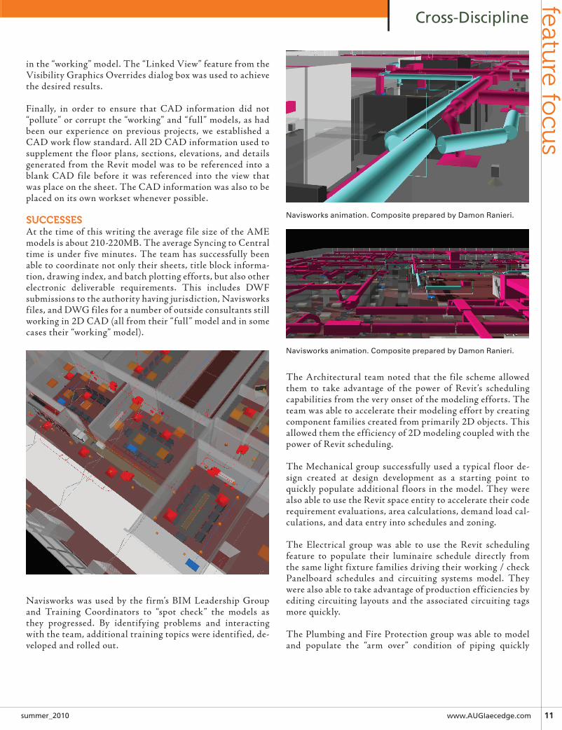
Navisworks was used by the firm’s BIM Leadership Group and Training Coordinators to “spot check” the models as they progressed. By identifying problems and interacting with the team, additional training topics were identified, de-veloped and rolled out.
The Architectural team noted that the file scheme allowed them to take advantage of the power of Revit’s scheduling capabilities from the very onset of the modeling efforts. The team was able to accelerate their modeling effort by creating component families created from primarily 2D objects. This allowed them the efficiency of 2D modeling coupled with the power of Revit scheduling.
The Mechanical group successfully used a typical f loor de-sign created at design development as a starting point to quickly populate additional f loors in the model. They were also able to use the Revit space entity to accelerate their code requirement evaluations, area calculations, demand load cal-culations, and data entry into schedules and zoning.
The Electrical group was able to use the Revit scheduling feature to populate their luminaire schedule directly from the same light fixture families driving their working / check Panelboard schedules and circuiting systems model. They were also able to take advantage of production efficiencies by editing circuiting layouts and the associated circuiting tags more quickly.
The Plumbing and Fire Protection group was able to model and populate the “arm over” condition of piping quickly
Navisworks animation. Composite prepared by Damon Ranieri.
Navisworks animation. Composite prepared by Damon Ranieri.

12 www.autodeskcatalog.com/AECEdge summer_2010
Cross-Disciplinefe
atu
re fo
cus
throughout the model through the use of groups, and copy-ing and pasting typical layouts throughout the models. This was done to ensure that this requirement was considered during ceiling coordination. This approach allowed the use of Revit or Navisworks for the team to analyze the ceiling planes and the areas above them.
ChallengesAs the project advanced and more users were spending more time in the model, there was not a way to ensure all information was on the proper workset, even with the “Open/ Close” workset strat-egy employed. Users also complained of confusion about where a bit of information might reside (i.e. tags belong to the view’s workset, and the object being tagged would be on a user created workset). As a result users were opening all worksets instead of just what they needed. This defeated the strategy of using work-sets to mitigate file opening times.
In addition, team members from all disciplines found it cum-bersome to open an entirely different model to analyze various aspects of the design. For example, if an architect wanted to com-pare the space layout to the program and finalize edits, in many cases all three models would have to remain open on the user’s machine at the same time. In another case, if an MEP team mem-ber was picking up markups, the markups typically covered the whole project so that user would also have open all three models and additionally keep AutoCAD open to address information authored in the referenced CAD files.
Due to staffing challenges in the Plumbing and Fire Protection group, those users had a tough time keeping pace with their coun-terparts in other disciplines in terms of their Revit skills. Even with additional emergency training from outside consultants, in house power users, BIM Leadership, access to the in house BIM blog, and “Just in Time” training sessions, the group ultimately delivered the project using CAD. At the time of this writing, the group’s training issues have been addressed and they plan to issue their next document set for the redesign and additional floors in Revit with the rest of the team.
The Architectural team was disappointed that they could not dimension anything directly to geometry in a link; typically this type of dimensioning was done in the “full” model. If another user (i.e. the Mechanical designer) opened up the “full” model, but chose to not open a number of links that had been used for dimensioning, they would be asked by Revit if they would like to delete the dimensions that could no longer be resolved. If they did not answer “yes” to delete the dimension(s) they could not open their file. In the end, the architects ended up dimensioning in the “working” files so the dimensions would adjust with the walls if they were moved. For dimensioning between new work in the “working” models and the existing conditions model, the architects needed to draw symbolic or drafting lines in the “full” model over the geometry in the linked model that they wanted to
dimension. This ultimately improved the files’ performance when opening and Syncing to Central, but was considered to be a draw-back of the approach.
As many users are aware, tailoring a view in Revit is not an intui-tive process. First time users grappled with getting their views to appear close to company and industry standards, and graphically their efforts were further complicated by the necessity to pull companion views from a “working” model into the “full” views referenced by the sheets. In such cases where certain annotation was coming from views created in the existing conditions model, and other annotation coming from another discipline’s “working” model, a significant amount of time would be spent troubleshoot-ing why printed sheets looked a certain way regardless of whether that result was desirable or not.
analysisNow that certain disciplines within the firm are working together in the same model more frequently, specifically Architectural and Electrical, we have discovered interesting developments emerge in project process and work flow. Historically, the Architectural group would place items such as light fixtures, data outlets, and receptacles in their schematic level CAD drawings to give clients and users a sense of how their space might be laid out. Since this was typically done in a set of files independent of the Electrical designers, a set of prints was made when the team was ready to have the Electrical designers begin their portion of the work. The design of lights and devices from the Architectural team was considered a starting point. As in many cases, the final location of certain items would be contingent on the Electrical designer’s analysis of codes, calculations, and products available that would work for the system. On this project, the architects, working traditionally at an early stage in the project created their own version of many of these families. This became an increasingly urgent issue when the team realized the hours and effort it was going to take to clean these families from the models in order to allow the Electrical team to begin their work using the fami-lies specifically developed for the Electrical views. In the end we found a way to work around the symbols and families that were placed at schematic design and space planning; we agreed that for future projects the official library of Revit families for the Electri-cal group would be used at all phases of the project process by all disciplines to allow the transition of responsibilities to take place more efficiently. This means that as families are developed, the input of all disciplines and users that plan to utilize the family need to be considered before the element can be part of the firm’s official Revit library.
Overall the main objective of the file set up strategy was suc-cessful. The file sizes were kept in check, and the team remained productive opening and Syncing to Central times remained rea-sonable. In the future we will continue to split models but make sure that the bulk of the building or project remains intact per discipline. Currently for new projects, Architectural and elec-trical work remain together in the same model, as do Plumbing and Fire Protection, while the site, Structural, and Mechanical models remain separate. Revit 2011 has included features to le-

www.AUGIaecedge.com13summer_2010
Cross-Disciplinefeatu
re focu
s
verage the use of linked models (i.e. tagging through a link), so the composite or ”full” model strategy is one that the BIM Lead-ership group still promotes and recommends depending on the goals of the project. There are features the team intends to use in Revit that require all the models for a project be linked together, such as drawing index schedules. It cannot be stated enough that the most important lesson for the team from this experience was that the lines of communication need to remain open and active outside of the Revit environment in order to take full advantage of the software and the BIM process. Teams need to know who to communicate with and how. They also need to allow time for regular communication with the rest of the Revit users on the project. This can be through weekly meetings, use of the Work-sharing Monitor, instant messaging, email, telephone and most likely a combination of all of the above. What is imperative is that the communication is comprehensive and focused. One user talk-ing to the person next to them is not effective communication on a Revit project. All users on a team need to be committed to the process and be willing to share information about their models,
listen carefully to each other, and then put that information to good use to benefit the entire team and project.
Damon J. Ranieri is an applications specialist at OWP/P, focusing primarily on the MEP Department. Damon has been heavily involved in the migration of MEP design to BIM since 2004 at this and his previous firm. Currently he is developing in-house Revit training and docu-mentation, and is studying the current strengths and limitations of interoperability between the trades’ preferred software. He can be reached at [email protected].

www.AUGIaecedge.com 15summer_2010
Cross-Disciplinefeatu
re focu
s Building information modeling (BIM) is a tech-nology driven phenomenon sweeping the AECO Industry. Prior to the current down turn owners were clamoring for increased efficiency and pro-ductivity in the planning, design, construction, operations and maintenance of facilities and the
infrastructure that supports those facilities. Many viewed BIM as a Panacea, and rushed to implement BIM programs. Institu-tional owners like the General Services Administration (GSA) and the United States Army Corps of Engineers (USCA) at the federal level, state officials in Texas, California and Wisconsin and a myriad of private owners adopted BIM guidelines of vary-ing quality.
In the rush to adopt BIM those owners overlooked the need to marry BIM to effective lean business processes and to develop integrated agreements and procurement processes that actually support and enable the use of BIM on one hand and lean construc-tion processes on the other. BIM alone can increase efficiency and productivity for a few industry stakeholders. But Integrated BIM will, eventually, allow owners to leverage digital assets by connecting real time web-based information about building com-ponents, supporting infrastructure, building systems, as well as maintenance and operations programs. The graphic below visu-ally depicts the correct balance between BIM, lean construction processes and the integrated agreements and procurement pro-cesses required to support those innovative new tools.
InTEgrATED BIM… oWnErs WAnT IT, hoW Do ThEy gET IT?Too often, owners – even sophisticated owners – have no idea how to procure effective BIM services. Further, too few construc-tors, designers, consultants and trade contractors understand BIM. Between cryptic BIM requirements in RFPs and cumber-some BIM guidelines owners seeking BIM seem to be confusing designers, contractors and trade contractors about what BIM is and why they want it. This article explores some – though by no means all – of the challenges to procuring an effective Integrated BIM. The AECO community must recognize the long term value of investing in Integrated BIM and deploying the collab-orative and integrated processes necessary to procure Integrated BIM services.
The current best efforts at BIM result in something called a Fed-erated BIM model which is an amalgamation of models created on disparate software platforms by a series of disparate entities bound together, at best, by an integrated agreement related to a single project. Few of the entities involved – be they owners, con-tractors, designers or software providers – are prepared to work together cooperatively and collaboratively. The software tools are not interoperable and cannot, generally, share BIM data on a cross disciplinary basis. Once cobbled together the Federated BIM Model is most often leveraged by constructors, both general contractors and trade contractors, to increase the efficiency and productivity with which they deliver their services. The occa-sional windfall is pocketed by the entity it falls too and others are simply frustrated by a series of strange new business processes.
Designers are particularly disillusioned with BIM as it calls on them to modify their business models, invest in new software, hardware and training and to accept the same fees for more work, at least the first time around. Even designers who recognize the
by: James L. Salmon, Esq
➲
Integrated BIM… Integrated with What?
Figure 1
Figure 2
1323-258_CAD_Advertorial.indd 1 9/13/10 9:57 AM

1� www.autodeskcatalog.com/AECEdge summer_2010
Cross-Disciplinefe
atu
re fo
cus
need to leverage BIM in order to remain relevant are confused by the new business models and don’t know how to “sell” BIM to skeptical owners.
The allegory of “Katy’s Birthday Castle” tells the story of the owner who receives a “Box of BIM Blocks”, with no idea how to reassemble the BIM Blocks, access relevant information or otherwise the advantage of the shiny the new digital asset that is purportedly being received. The full story of Katy’s Birthday Castle is detailed on the Collaborative Construction blog (http://collaborativeconstruction.blogspot.com/) but the bottom line is the Federated BIM Model depicted above is torn down placed in a box, leaving Katy with a “Box of BIM Blocks”.
A few sophisticated owners can utilize some, though not all of the BIM Blocks, but as far as most owners are concerned the Feder-ated BIM Model might as well be a Braille Rubik’s Cube. The “Box of BIM Blocks” and the Braille Rubik’s Cube below depict
the dilemmas faced by owners.
InTEgrATED BIM… WhAT Is ThE soLuTIon?Integrated teams of BIM enabled stakeholders formed in advance, trained together and deployed in an integrated, cooperative and collaborative environment is the key. That process is neither simple nor cheap but it is necessary if the AECO industry wishes to leverage BIM effectively.
The “business purpose” of a single family home, a convenience store, a storage facility, a commercial warehouse, a hospital, a server farm and a regional hospital are all very different. The owner of each facility has one level of interest in the digital assets associated with each such facility and its supporting infra-structure, while the community at large, the owner’s employees, emergency personnel and others who interact with the facility
have other interests that merge, diverge and even clash with the owner’s interests. Real digital assets – i.e. Integrated BIM – that can be recorded, analyzed and accessed intelligently over time by relevant stakeholders will enable more of those staked holders to
make more and better decisions about how best to utilize such facilities.
ConCLusIonToday more than ever we need to leverage information intelli-gently, effectively and efficiently. Integrated teams that learn to do so, throughout the life cycle of a facility, will increase the ef-ficiency with which they deliver planning, design, construction, operations and maintenance services, gaining a market advantage over competitors who fail to do so. Entities and individuals in-terested in learning more about Integrated BIM, lean business processes and the integrated agreements and modified procure-ment methods necessary to support integrated teams should contact the author for more information.
James L. Salmon, Esq. President, Collaborative Construction Resources, LLC is a collaborative consultant and the creator of these IPD in 3D™ concepts. Salmon advocates the use of advanced BIM technologies, Lean Construction methods, Collaborative Agreements and other IPD in 3D™ processes. His Collaborative BIM Advo-cates group provides free membership, national networking opportunities, custom symposiums and online webinars.
Figure 3
Figure 4

www.AUGIaecedge.com 17summer_2010
Cross-Disciplinefeatu
re focu
s
An Architect’s perspective on BIM in Construction World
Having worked as an Architect for twelve years in the West, Midwest and East Coast, and then recently accepting the BIM Manager position with a California construction company, I have a unique perspective. When I started working in
architecture, the 3D models being created were solely for client presentations. The models were meant to woo the clients and to allow the client to visualize their new building. Significant changes have happened in the profession since then. The con-struction company I was lucky enough to get a position with is DPR. If you aren’t familiar with them, here are some basic facts on the company.
DPR Construction (www.dpr.com), which was founded in 1990, is a unique technical builder with a passion for results. Ranked in the top 50 general contractors nationally over the last 12 years, DPR specializes in technically complex and sustainable projects for the Advanced Technology, Corporate Office, Healthcare and Life Sciences customers.
What interested me in DPR is that they are continuously looking for opportunities to improve the construction delivery process by providing a higher level of quality service on projects of all sizes and complexities. DPR is a proven leader in green build-ing, building information modeling (BIM), and lean/integrated project delivery. A fundamental reason that I took the position with DPR was because of the company values that it embodies of integrity, enjoyment, uniqueness, and ever forward. The fourth value is important in terms of BIM along with DPR’s company motto which is, ‘we exist to build great things.’ These great things are built better by using the right tools. DPR empowers and encourages its BIM engineers to choose and learn from any soft-ware they judge necessary. As an example of their commitment and expertise, DPR’s employees have played a dynamic role in the development of various software platforms.
The use of Building Information Modeling has been a fundamen-tal component to meeting the ever increasing demands of clients, shortened building schedules, and tighter budgets. The major software/ tools that DPR uses and I have become familiar with in the Newport Beach Office are as follows: ProjectWise, DProfiler, Timberline, Innovaya, Revit, laser scanning, MWF, Solibri and Navisworks.
There are many tools we use at DPR. Usually the project con-straints, owner, site, existing conditions and/ or DPR staff drive the needs for particular tools on a project. One owner may want
a particular deliverable of a model of their project with every out-let, light switch, and component labeled. Another client’s needs may focus on prefabrication of the shared head walls in a hos-pital. Each new project gives us a chance to find a way to make it happen. In order for BIM to become more useful it needs to have a comprehensive understanding of the entire process from operation, preconstruction, self perform, to construction. Each of these areas has break downs in efficiency. If each of these areas is better understood then the tools available can be skillfully uti-lized. Here is a brief synopsis of what I have learned at DPR in the past 3.5 months. A crucial component to the project’s success is communication. When teams are not communicating or working off of old data; they are being inefficient for that project. Every BIM project at DPR begins with a team meeting where the project objectives and goals are outlined. From there each team player in the meeting states the required information to complete their tasks. In these meetings at the beginning and throughout the project we are able to tap into the collective knowledge—this is what drives the team’s success. The tool that DPR uses to facilitate better communica-tion between the team and the subcontractors is a product called ProjectWise version V8i by Bentley. It acts similar to a FTP site but it more effectively manages versions, allows for faster copying of changed documents, and easier coordination of documents; all within a secure and backed up environment.
Once ProjectWise is in place our estimators can utilize the shared project models posted in ProjectWise. As the architect or engineer is working on their model the updates are sent di-rectly to the models from which estimators are working. We have started to experiment with using DProfiler by Beck Technology,
➲
Figure 1 - Model Based Estimating - Setup Phase
by: Vanessa Vanbeusekom
1� www.autodeskcatalog.com/AECEdge summer_2010
Cross-Disciplinefe
atu
re fo
cus
for conceptual based estimating. DProfiler software is designed to improve the early design decisions made in preconstruction; these decisions inform the designers on the cost ramifications of the change. It is a tool that enables greater clarity before moving forward on a design that exceeds the budget.
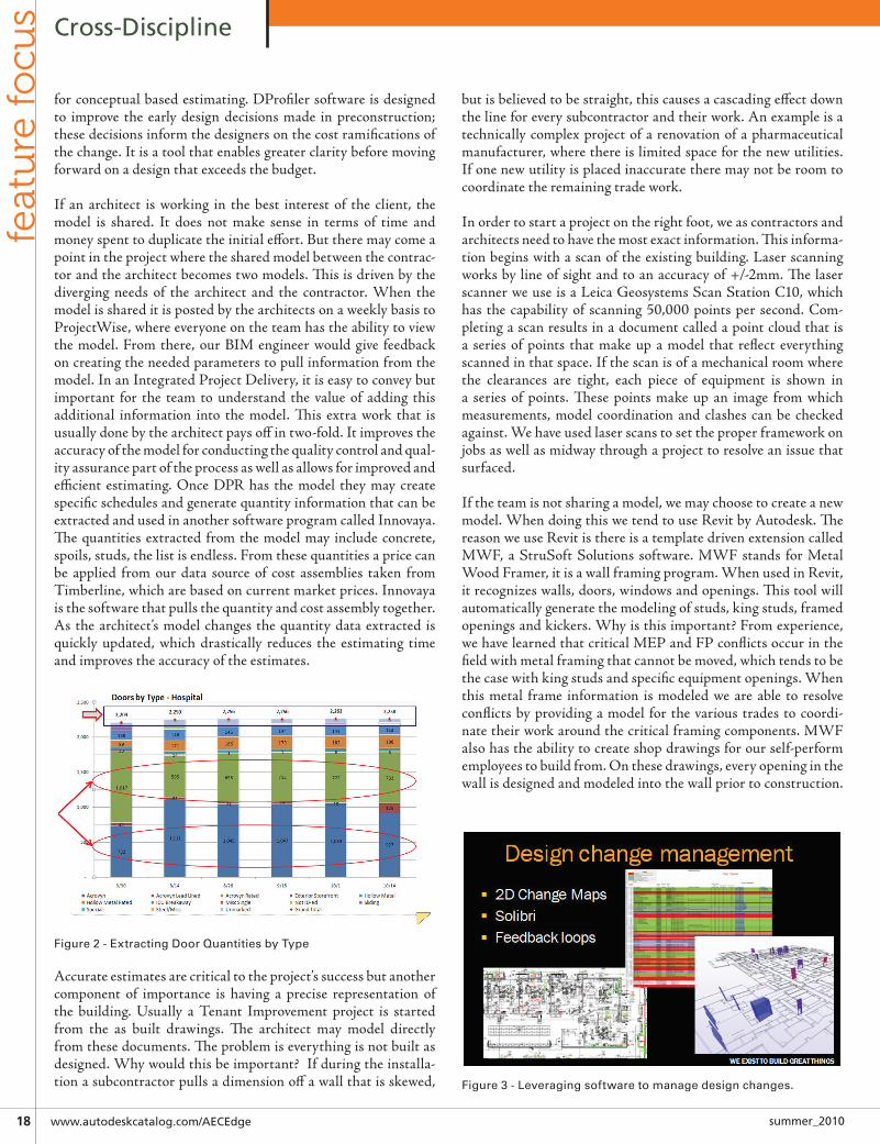
If an architect is working in the best interest of the client, the model is shared. It does not make sense in terms of time and money spent to duplicate the initial effort. But there may come a point in the project where the shared model between the contrac-tor and the architect becomes two models. This is driven by the diverging needs of the architect and the contractor. When the model is shared it is posted by the architects on a weekly basis to ProjectWise, where everyone on the team has the ability to view the model. From there, our BIM engineer would give feedback on creating the needed parameters to pull information from the model. In an Integrated Project Delivery, it is easy to convey but important for the team to understand the value of adding this additional information into the model. This extra work that is usually done by the architect pays off in two-fold. It improves the accuracy of the model for conducting the quality control and qual-ity assurance part of the process as well as allows for improved and efficient estimating. Once DPR has the model they may create specific schedules and generate quantity information that can be extracted and used in another software program called Innovaya. The quantities extracted from the model may include concrete, spoils, studs, the list is endless. From these quantities a price can be applied from our data source of cost assemblies taken from Timberline, which are based on current market prices. Innovaya is the software that pulls the quantity and cost assembly together. As the architect’s model changes the quantity data extracted is quickly updated, which drastically reduces the estimating time and improves the accuracy of the estimates.
Accurate estimates are critical to the project’s success but another component of importance is having a precise representation of the building. Usually a Tenant Improvement project is started from the as built drawings. The architect may model directly from these documents. The problem is everything is not built as designed. Why would this be important? If during the installa-tion a subcontractor pulls a dimension off a wall that is skewed,
but is believed to be straight, this causes a cascading effect down the line for every subcontractor and their work. An example is a technically complex project of a renovation of a pharmaceutical manufacturer, where there is limited space for the new utilities. If one new utility is placed inaccurate there may not be room to coordinate the remaining trade work. In order to start a project on the right foot, we as contractors and architects need to have the most exact information. This informa-tion begins with a scan of the existing building. Laser scanning works by line of sight and to an accuracy of +/-2mm. The laser scanner we use is a Leica Geosystems Scan Station C10, which has the capability of scanning 50,000 points per second. Com-pleting a scan results in a document called a point cloud that is a series of points that make up a model that reflect everything scanned in that space. If the scan is of a mechanical room where the clearances are tight, each piece of equipment is shown in a series of points. These points make up an image from which measurements, model coordination and clashes can be checked against. We have used laser scans to set the proper framework on jobs as well as midway through a project to resolve an issue that surfaced.
If the team is not sharing a model, we may choose to create a new model. When doing this we tend to use Revit by Autodesk. The reason we use Revit is there is a template driven extension called MWF, a StruSoft Solutions software. MWF stands for Metal Wood Framer, it is a wall framing program. When used in Revit, it recognizes walls, doors, windows and openings. This tool will automatically generate the modeling of studs, king studs, framed openings and kickers. Why is this important? From experience, we have learned that critical MEP and FP conflicts occur in the field with metal framing that cannot be moved, which tends to be the case with king studs and specific equipment openings. When this metal frame information is modeled we are able to resolve conflicts by providing a model for the various trades to coordi-nate their work around the critical framing components. MWF also has the ability to create shop drawings for our self-perform employees to build from. On these drawings, every opening in the wall is designed and modeled into the wall prior to construction.
Figure 2 - Extracting Door Quantities by Type
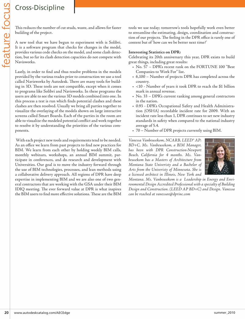
Figure 3 - Leveraging software to manage design changes.

�0 www.autodeskcatalog.com/AECEdge summer_2010
Cross-Disciplinefe
atu
re fo
cus
This reduces the number of cut studs, waste, and allows for faster building of the project.
A new tool that we have begun to experiment with is Solibri. It is a software program that checks for changes in the model, provides various code checks on the model, and some clash detec-tion, but so far its clash detection capacities do not compete with Navisworks.
Lastly, in order to find and thus resolve problems in the models provided by the various trades prior to construction we use a tool called Navisworks by Autodesk. There are many tools for build-ing in 3D. These tools are not compatible, except when it comes to programs like Solibri and Navisworks. In these programs the users are able to see the various 3D models combined into one. In this process a test is run which finds potential clashes and these clashes are then resolved. Usually we bring all parties together to visualize the overlaying of the models shown on large interactive screens called Smart Boards. Each of the parties in the room are able to visualize the modeled potential conflict and work together to resolve it by understanding the priorities of the various com-ponents.
With each project new tools and requirements tend to be needed. As an office we learn from past projects to find new practices for BIM. We learn from each other by holding weekly BIM calls, monthly webinars, workshops, an annual BIM summit, par-ticipate in conferences, and do research and development with Universities. Our goal is to move the industry forward through the use of BIM technologies, processes, and lean methods using a collaborative delivery approach. All regions of DPR have deep expertise in implementing BIM and we are also one of two gen-eral contractors that are working with the GSA under their BIM IDIQ meeting. The ever forward value at DPR is what inspires the BIM users to find more effective solutions. These are the BIM
tools we use today; tomorrow’s tools hopefully work even better to streamline the estimating, design, coordination and construc-tion of our projects. The feeling in the DPR office is rarely one of content but of ‘how can we be better next time?’
Interesting Statistics on DPR:Celebrating its 20th anniversary this year, DPR exists to build great things, including great results:
• No. 57 – DPR’s recent rank on the FORTUNE 100 “Best Companies to Work For” list.
• 6,100 – Number of projects DPR has completed across the country.
• <10 - Number of years it took DPR to reach the $1 billion mark in annual revenue.
• No. 33 – DPR’s current ranking among general contractors in the nation.
• 0.93 - DPR’s Occupational Safety and Health Administra-tion (OSHA) recordable incident rate for 2009. With an incident rate less than 1, DPR continues to set new industry standards in safety when compared to the national industry average of 5.4.
• 70 – Number of DPR projects currently using BIM.
Vanessa Vanbeusekom, NCARB, LEED® AP: BD+C, Ms. Vanbeusekom, a BIM Manager, has been with DPR Construction-Newport Beach, California for 4 months. Ms. Van-beusekom has a Masters of Architecture from Montana State Univeristy and a Bachelor of Arts from the Univeristy of Minnesota. She is a licensed architect in Illinois, New York and Montana. Ms. Vanbeusekom is a Leadership in Energy and Envi-ronmental Design Accredited Professional with a specialty of Building Design and Construction. (LEED AP BD+C) and Design. Vanessa can be reached at [email protected]