by l-.45 8.!people.csail.mit.edu/saltzer/ctss/multics-documents/g00s/g0010.pdf · 1 o: mw ..ncs...
TRANSCRIPT

1 o: MW .. ncs Repc»i\·or-y
GENERAL fLECTRRC COlv'\Pl,NY Compute!:" Deporiment
Phoenix 0 Arizona
The aHachr~d document, prepcured by H. D. Mo~·ihe'<YS of ~·he l-.45 i 8.! D ProgJ;'C:;mm ing gwoup is benr's dlr;h"ibuted for general inte~·est o The info~matiei1 pfe5e!"1~ed ~~hoa..Jicl be inrer:r ... ~'ei·.zcl h:> r.-epli'esoni· ~he infCl~t711Cii'ion needs of 645 T & D prrogroms and not nece~$i:idly the r.otYtiC>t of the infl'.1crn ::~~ion.

• •

r;·,
·);. ' . . .
·, .
PERIPHERAL T&D INTERFACE WITH 645 SOFTWARE MONITOR ' ,(. ;
.+~:
I. ~PROGRAM STORAGE -Approximately 60K of storage will be required on the DRUM, MD-S2, or DSU~.for on-line T&D Programs. These programs will be backed up on Mag. Tape for the case where the normal storage device is not operable.
II. !@_PROGRAM CALL - Th~ T&D Program wiil be called into memory by' a request from a Product Service man. This call should be made fr~ a "spec." Maintenance Console or Comnunication Terminal. The Program Call should be enabled from more than one input source.because of the 'possibility of failure of any input source.
III. T&D PROGRAM LOAD - The ,Software Monitor must be able to search for the T&D Program . from information contained in the T&D Program Header (first 11 words of the program). · The Program Header (fig. 1) is used as a form of communication between the T&D ,
~
Program and the Monitor Program controlling it. It provides the Monitor Program with Program Number, Program Name, Test Identification, Program Size, Address of Table whic>t contains entry points, Maximum. Time· counts to wait for interrupts, and type codes of peripheral requirements. The monitor in t~rn supplies the T&D Program with counts for "Special" interrupts, channel number for required peripherals, device numb·:!rs for required peripherals, and the type code for the required peripheral. The Eormat for the T&D Program Header is as follows:
0 ~ 12 1 ~ . 39 t . I
I I I
l-11 I ..
/ r
' I I 2 0 I 2 0 i. PHASE NUMBER BCD, PROGRAM TYPE CODE I 2 0 I'
~I . SUB TEST I .
W2 4--. PROGRAM IDENTIFICATION ~ TEST NtrMBER !IDENTIFICATION
W3 - I
•, . If: OF MEMORY :WORDS USED BY 41 ZEROS ~j
I 'I'HT~ 'P'R nrm AM . · . , , · .. 1 I
W4 -
TERMINATION INTERRUPT 4-SPECIAL INTERRUPT DELAY CQUNT ·~ . .:.. . .. 4 DELAY COUNT "' (NOT USED WITH MD-32 ·TESTS)
'' '· .W5 4-- ZEROS (USED ·As SPECIAL INTERF UPT COUNTERS BY T & D CONTROL). ,
~ :---
W6 .4: ZEROS §P' START ADDRESS OF TEST XFER TABLE
W7 1-- .. : I' .NlJl.'IBER OF ENTRIES 4- ZEROS
" I IN TRANSFER TABLE I
I
W8 UNUSED ,_.
: . W9 tTh.TUSED
WlO I ~KI
I TYPE CODE .OF. , ' . ' I Pl!:RIPHERAL REQ .• · I
I. I TYPE CODl'; OF· I I Wll . ! X : . PERIPHERAL REQ.
. 1.-.
·,· . ·'
Figure ·1 I .
II
/ ••• l .

Page. 3
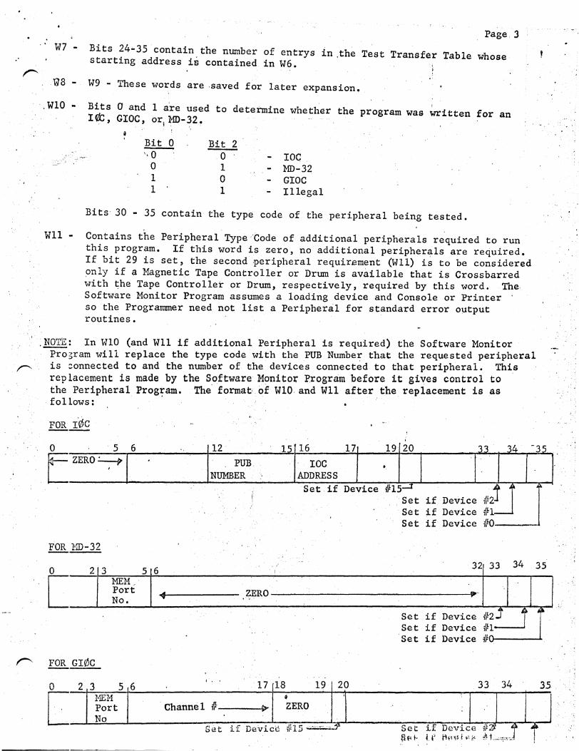
W7 - Bits 24~35 contain the number of entrys in .the Test Transfer Table whose .· starting address is contained in W6. . r !
'@8 W9 - These words are -saved for later expansion.
·. WlO - Bits 0 and 1 a·re used to determine whether the program was written for an IQt, GIOC, or1 MD-32.
Bit 0 Bit 2 ···O 0 IOC
0 1 MD-32 1 0 GIOC 1 1 Illegal
Bits 30 - 35 contain the type code of the peripheral being tested.
Wll - Contains the Peripheral Type Code of additional peripherals required to run this program. If this word is zero, no additional peripherals are required. If bit 29 is set, the. second -peripheral requirement (Wll) i~ to be considered only if a Magnetic Tape Controller or Drum is available that is Crossbarred with the Tape Controller or Drurn, respectively, required by this word. The Software Monitor Program assumes a loading device and Console or Printer so the Programmer need not list a Peripheral for standard error output routines •
. ~: In WlO (and Wll if additional Peripheral is required) the Software Monitor Prosram will replace the type code with the PUB Number that the requested peripheral is :onnected to and the number of the devices connected to that peripheral. This replacement is made by the Software Monitor Program before it gives control to the Peripheral Prog~am. The format< of WlO and Wll after the replacement is as
-follows:
0
E 5 6 12 15 16
ZERO~ PUB. IOC ' ADDRESS NUMBER
Set. if
FOR MD-32
-0
t 2 3 5 6
MEM/-Port ZERO No. ... . ....
17
Device
19 20 33 34 -35
•
1115_.,;:J ~ ~
Set if Device 1/:2-J Set if Device 1fl-Set if Device 1/:0
32 33 34 35
_... ..
Set if Device 1nJ j i Set if Device #1----~ Set if Device #0~_ ------~
I'""" FOR Gie\C
0 I
17 18 19 20 2 3 5 6 33 34 35
[ MEM ~ I ' Port Channel f/: S>- ZERO -·
No
~~~}~~ ~r~-c,,._1 r Set if Devic'd tJ 15 -=-.:..,_? Set if ~ f< •· U'

. ·
.... ·
i •. ': ~ .
0
I
l\.
· ~- Page 4 ·-,::-: .. ... . ~.. -· . '
' ,,
· III. T&D PROGRAM LOAD - (cont.inue.d) ;J\ '. ''
t. ' ' I " ·,·' \ .i · .. ·. ·.· ~-·
> . IV.
-\
..
If a program.lj.a,:s. an additional'peripheral requirement in Wll and such a peripheral is not available, the Software MonLtor ~rogram ~ill output a mess~ge to th~ 'operator and ,will not attemp~ to•'execute the program. ·The exception to t,his cas~ is when· b:i.t 29 :i~s set in. Wll.
'.
• I ' .. .. '
., .
T&D PROGRAM HASTER MODE ENTRIES·- The Soft't·ulre Monitor must ... ·· to be able . to service a set of T&D Ma.ster· Mode Entry rountines and handle the~ as described .. below. It should be ~e~tioned.~hat_the address f~e~ds of a!l ~ c~ands need :":.~ :,:<: :;.~:z.::::.y z. . .s: "'?~.:.::.::::..:::'!. '.-":x. !::..:: CJ s:e:: :o:.:.-=- ::c::::::te T~ t'.iJ:.IE).
-~. .. ', .
Each ·time the writer of a Common :Perfpheral T&D Program wishe.s to: is'sue . '~. ' a command to a periphet:al, he must conununicate with the Spftware Monitor· ' Program by' a Mas'ter Mode Etitry with the .. following call sequence. The. : ··...... . Software Monito.r Program· must he· able to handle this call sequence when· ·
. peripheral is conne.cted .tq a GI0C ~by using the' indirect Dq.T. for I¢C · simulation. p_· ·
. . , . . ' :·.~ .. ~ '
6· . , ; ·:-·
.. . .
,·.
.. ..
. ' ...... , :· .''. : ~ ... l / ..
. . , .
- 9 -12 l i .. ~.I·.
.. . :
15
. ··'[ •'
·. :, .. . ·.·
· . ' .
.. 18
t
21 24·'
I .... · ' . . . . l' .. ~ :.:• ~ •· . . . .
....... 27 .. 30 . ~-~ . . .. . r
. I
. 3 ") . . •• !4 . .,., .
I .· .
1 I •• • I ' -r--------ZERO-------.,..-~ lO o· q_ 0 0 ·o·o 1 !lli-<--..-ZERO----:~
·¢· · . · : ·' • I PUB 'I¢c '1 r¢c 1 · • ' -~ l?-CO~E -4- ,· DEVICE -COD~ r ADDRESS !Jli.l:RH3I COMMAND : :. 0 0 · 0 0 0 0 0 . :RECORD COU~
. ' ~ _'4-~· STARTING oF-.TA ADDREss FOR Tius ocw~ · 1 zoNE : 0~ACIYoN; No·. oF woRDS TO BE XFERRE
_ ·· · . I CONm. 1 1 CODE I < ... BY THIS DCW. > l ~:(--ADDRESS OF NEXT DCW TO ,BE USED : '. ZERO .• __:_, r------------------:-__;_ ____ ~,-~--·,;...· --~---~__:-.:..,· r---~·-· _' ...
. -~:...-----ADDRESS Q[_FIRST DCW : . ~- ZERO. !RECORD CO'CJ1
I b-" .f'/lA T!JR . , . , su 1 sTA.I?us ·, SUB-STA'I'US· · : 0 0 -:o o: 0 0 ·1 I¢c STATUS ; , ' 1 • 1 •
• 1 Ignl EXPEC'JEO: ~E~PECTEn' .. :: . ' . '• ~ I EXPECTED I 0 0 0 .0 0 0 0 . : Tt :'Irs: R::
7 <E:-------:-_.;:;"·-· "'-:---------------· ZEROS .. ; .:. I I I 1 . .... .. . ·.. .. .. ~ ...... · .. ' .. ~ .. ·""' ·/ T . ~-
: .~\_..;.._-START ADDRESS OF .NEXT TEST---~· I .. .::::;·l''l l 0 ·o 1 0 0 .. 0 0 'START ADDRESS OF LOOP·-----~ :~ .. ~-1 1 1 0 0 1 0 0~·0 t ~.----------- NORMAL RETURN LOCATION
: \. '.i .... :J. ·, ••.• :. :. i ... , ..
,.._ .... ·. ·.· .. •.:···
·: . ~.' (' .. •' .. ···:· ..
. : .· ~ ~ . ~ ' .. · .. · .. ·· ' . ' .. ·. ;"·:·\ ..
I •• • •.. ·-" .. • •. · '·'
• .... •.' .......... ,·· .. · '' .. '\' ,,, . . , ·.·.. . ..
' '
. · :•'. ~: :: \ '
.... t
I ~---ZERO-----~ I
. ......

..
I
\ .
•
Page 5
Wl MME rfo. ,•};
W2 - Primary Ma~lbox Word ·:' PUB addre~~ (Bits 12-15) is·provided by programmer from information furnished'.;by Software Monitor Program •
. W3 - Secondary·. mailbox 1/:1 Word.
W4 - Secondary mailbox #2 Word.
..
Upper and (lower address limits will be provided by Softwar.e Monitor Program. :
. W5 - Secondary mailbox #4 Word. Upon interrupt, Software Monitor Program wi11 replace record count (Bits 30-35~ with record cou~t residual in call sequence •
. W6 - Type of interrupt and status expected upon interrupt. Bit 1 - Set if substatus is to be ignored by Software Monitor Pr-ogram
-Error Check. Bit 31- Set if terminate interrupt is expected. Bit! 32- Set if initiation. interrupt is expected. Bit 33- Set if special interrupt is expected. Bit 34- Set if program wants immediate return ...
If this bit is set, the Software Monitor Program must give control back to the T&D Program immediately after the connect command has been issued. This feature is used sparingly by the T&D Program and only when the program has to have control back to perform certain functions •
. Bit 35- ·Set if program wants standard err·or output.
If this bit is set, the Software Monitor Program will compare the results of the interrupt against what was expected and output an error message of the following type if an error is detected.
1 . .
Standard Peripheral Error Output Connected•To IOC . . .' ......
" , .. PROGRAM AND TEST IDENTIFIER . >~<- ...:, ~--
&;; * MT 02
.EXPECT 'ACTUAL
,/ o;'
PUB-01 DEV-04 OP-46 COM-01 IOC-0 . ,., .. ,.,'
· T READY ~:00 COO I REJECT 10 ·OO
' \ \ '
~IOC MEMORY S.TATUS SUBSTATUS MAJOR STATUS TYPE OF INTERRUPT
, . 1, . I = INITIATION T = TERMINATION S .. SPECIAL.
·, .
•'
I.
.,
. ' ' \:,
..
jl
..... ·
I' ' ~: \
I ..
•'
.·, ' .. 'I
I . ' ' ' •• 1

.·
1
. •'· ., ' . .·~ .
., (
• if ,.
;~
!-.~~~
MAJOR STATUS REPRESENTATION:
00 01 02 03
' . 04 05 06 07 10
11 - 15
READY D BSY D ATT ALERT EOF REJCT INTER
· L TER C BSY ILLEGAL"·.
Page 6
If interrupt is not received in allowed time. NONE will be inserted as major status.
Standard Peripheral Error Message Connected To' The GIOC '
10 '20 30 40 50
... / ,..-------· PROGR.pf AND TEST IDENTIFIER
t/ CCW (XXXXXX) , CONNECT WORD (XXXXXX) . -·· ·. ·'· "··· *IOC2 7B DIAG CHAN COMMAND DIAG C P ·
XX XXXX XXXXXX XXXXXXXXXX X X
WORD A WORD B
TYP TER EXH EXT INT XPL CONT EX TEN ADDRESS TALLY s p LPW X 0 X 0 X 0 xooo XX xxxxxx xxx.x 0 0 ll::V! .. .. ... .. ,_..,. ' ,. , ... ,..., .. ,!P' .... ,~...,.,.,.,.,:-- ,.., ... .,..,'!"' .. •.. ... "" .... ... .. .. .... .. ..... , ..... ...,,~. .l:~..& .. .t.w_. ... ~~ ........ "l>· .....
'.,,-., . .,.. ...... • . • . • •,I .. ~. '
STATUs· CH TYPE CAUSE CHAN STATUS .. ' EXP X A XX. ' xxxx xxxxxx
A 2?C xxxx xxxxxx ACT X lf.SK
EXP ACT V.SK
""·
·• ·.• ..
l •.•
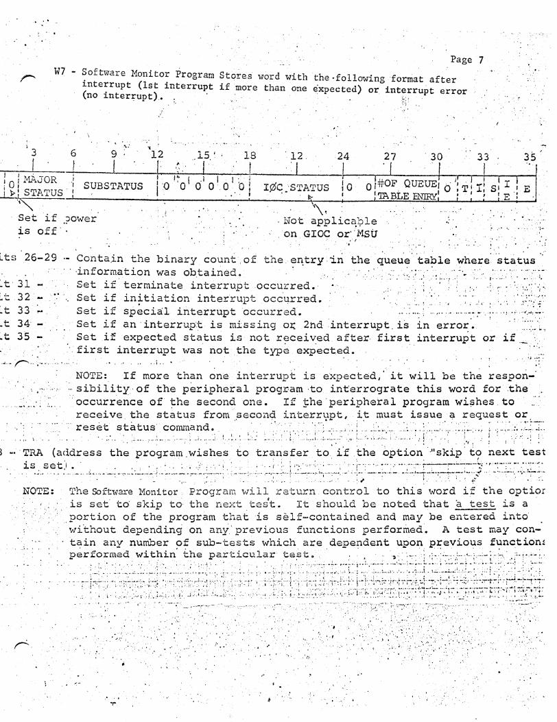
W7 - Software Monitor Program interrupt (1st interrupt
Page 7
Stqres 'tV"ord with the ·following format after ',\:
(no inter:t;upt). :. · if more than. one expected) or interrupt error ,,
·r;: ···?'
l ·,
,. ··.,· . ,. _, .. , .. '
3 "'. 6 9 12 .. 15. ~ . 18 ·. 12. 24 27 . 30 33 35 . , , . !1--~'---rr~~~'~··~+'~~-:~'~-4-~~--~~~~
~ o I MAJOR ·: SUBSTATUS I' -o. '~ o 1 61 o 1. o 1 n ,! I¢c ·s'rATus o r#OF_ QUEUE, o ': T 1 I: s1 I 1 .E .ll: STATUS. I . • 'TABLE ENIRY' • ' , IE·: '\"" _.__ _ ___.;......,...._~-:----. -.. -.. ----'----...!:~. __ -1...!!.!.!: .•. ~ .. ~.~.:!:£::. !:.1--L. .. ,.....£-......_j. ·:....£, ~...J
Set if ~?Ower .. ."~. . Not app1ic~};:lle .: · ·· .. is off· · : · . on GIOC or·· M.SU ,. ,. ·· ··;-
L ts .26-29
~t· 31 ~t 32. ~t 33 ,.,.
.· .. , . . 'o ~ . I ; • . .. . • •
Conta.in the binary count, of the. :n~try. 'in the queu'~· ·ta~1e where. stat\lS ···information was ob.tained. · · ·. ·: ·:·:·'·-·' . .' ·:; .. ,. .. • ~ ; ..... ,: .. :.·.·:·.·::.·::.-
Set if terminate interrupt .occurred.· .. · , :; ; .. . . ; :.· .: . ... : .. ~ .. ::·-;: Set if in~tiation interrupt dcc.qrred. · · ....... · · · ., , .. ' .. : ..... ·::,:.::;-f~.· Set if special interrupt occurred. - ... : .... ; ... , .............. ~ ·. ;· ... i _., ..... _ .• ,.: •.
Set if an· interrup·,~ is missing o~ 2nd ·interrupt. is in error. :.'.'.'.:.·~. Set if expected status is not received. after- first interrupt or if
. .. . >.first interrupt was not .the typ~. exp-ected. · : · · ,,..........__ ' .e' ,,o ' ' ' ,,',,, I •' '', .•,& •.'::
.~ ... r .... ,. ............. ·.. • ·.
NOTE: If more than ~ne interrupt is e~pected/ it will be the respon-. ' · .. ·:· ,_ ... -... sibility.· of the peripheral program ·to int:errograte this word for :the .
.. ... _ .. :.· . .'.'... :occurrence of '!=he second one. If !=he. periphera 1 program wi~hes. to .... receive. the status from ~econd interr~pt, it must issue ~ request or.
:·. :. ·, . . ·: res~~ ... st~~.~~ .. ; .. ~-o~a~~ .... ;. t.~·-: ~.~··_: ~.-: ... < i···: ·:: .. ::: ... ;_.:;·-,-.~:··_:::.1 .. :.::. :;::.~.~·';" .. :.::~.: ,: ~···:·:-<·:·· :--~:·: ·:~ j .; .:.:~.~:<·:~f·1~:-~ ~· · TRA (address the program .wishes to transfer 'to, ff the option ... skip. to next test
is s ~~-) .. ~.-: .. c •. _ ... -·~., ... >.~~ .. : ... ) .. ~--~-_:_-'~~:~.:; ... ::~ .. : ..; : .~: .... ; ... ~ .. :.~,::~.): .. ) '.:·::~;~.~~...;"~:··-->~: ,·.; .. ::~: ~::_~:·.~.~~-.- .. :.·_;:+.~:~~F;~::_) .: ~~;-~_-.:~~.~::;:·~:~:--.~ •· • • • '• ' I • , fT ..-
NOTE: The Software Monitor .. Program will return. control to this word if the optior . · . is set· to: skip to the next tes4t. It should be noted that 'a test is a .. ',·.portion of the program that is self-contained and may be entered into' · wi'thout depending on any.· previous functions performed·. A test may con
tain any number of sub-tests which are dependent upon previous function~ p~rformed within· the particul~r· te~t •... , .. · '; .. ,_.,. ';-::.; ·;<·~;:·,;-- :'· ·;.-~~-; .. :\· .. ~:·:·~-~-
.. · ·· ..•. • ·· ·· ,.;:,!--: ·~;:ij,;•:: :-{~ =i•.::,.·+:;':::~: :~ ; .. : ... :·r+iiJ·-j~~§:~;·f_~J::f~:j~~~~ttJ~~:H:~~H~%~-8.#~ r • .• ~· ·•- ,..., •
~ ......... --::·· ................ ~ ' ·:. . ·, ; . ... · ..
·.:, ..... : ·•
.. -. ', -: - ....... : .·.-·.··.·~.:,:·.:--~·~·'(,/:-::"· ~·.::_,.,"':F::·::~·· ··:-~~·:·.:·;:p~·~/~·.- ........ _,. ·-··, ·· .. . .: . . .. .. ,)' .
: ~ . ' .... : .. .. : . . · ·:,.. ·, ·. :,· .. ::.' .. '•· ·.· . •: ," I I > •,r • ' : : ~· •'' J 0 ', • •" ••
:, . I ' ,.,•: • •; .:· o! I ~ ': . :: ... · .. ·., ·~ ::,.· ; ; . . . . . . . .... ; ... :_.'.·' . ,,··:.. . . · ... '
.. J ' . : • ·, h ... • ·~.' \I c. . . ·~ •. ,.f.'.:: :: .. ·~·~·:,•<, 1' ',.• '•
,· .. ··,· .... . .. \.
._ ......... -.. -. ... -~ ... ·, ·· ... :·:, .· .. ·., ,.,
..... . ·.' . . ~:~: ' . . ·: . •..
•'
• : ., .' .' •• j. •• ~· .....
..... · . .. . .... ,: ,. .... . .; . 'I ·• 0 t 'o, .'(:,
" . . . '' . ·. .
., . . ~ . • • • I
, . ..,.. . ··:" .··· ,·

. . ..... . ·-"~·.,
Page ··a: ; . . . .
W9 - TRA (address the program wishes to transfer to if the option tc:;> "loop" is taken) • -· -· ; ',;\ \:
...
w1· . '
W2
W3
W4
W5
W6
W7
W8
W9
WlO
NOTE: The Software Monitor Program will return .control to t;his word if looping ...1 is desired. Control ':Jill be returned to W9+1 if looping is ,"Q.ot desired.
B. Input/Output Command Initiation For GIOC Test'i.ng· ::.:
0
Each time tl)e writer of 'a GIOC T&D Program wishes to issue an·~I/0 command ''" to the GIOC ~ he must communicate with the Software Monitor ·Program by ·a
,.
Master Mode Entry having the follmving call sequence:
11112 23 !24 2911 . . ' 35. 5.16 17 18
I I I T
0 0 0 0 0 0 0 0 0 0 0 0 0 1 0 1 0 0 0 0 0 0 0 0 0 0 1 o o o o o o o o· o · .
-f >l : I r . Mem •. MBZ except diagnostic connn~md D C C Port.
MBZ except Channe i No~- Channe~ Command(s) diagnostic
0 s c ·q,. 0 0 EX H 0 0 0 Int
0 0 0 0 A 0 0 0 0 0 0 0 0 0 0 Address
,Sig Extension
DCW address Tally OOPOOOi
Expected Status List Address 0 0 0 L C I 0 0 0 0 0 0 No. of Int. M Expected
Actual Status List Address 0 0 0 0 0 s 0 0 0 0 0 0 No. of InL c Received
Return location i~ Next Test option.set '•
Return location if Loop option set
Normal return location .
MME 20 .·, . '• ..
i
CIOC ..
ccw
LPw(A)
LPW(B)
Expect· ·.
.(\..ctual' ·
. : ,.,J.. Co.ntrol. Wd. ·
\~·
Control Wd~
Control Wd •
Wl .. MME 20
·-,, ..
~2.· Connect Word
This word will be moved, without alteration, to location x in the Mon:i.tor program (which is in the same .memory controller as the GIOC mailb~es). A CIOC x command will be executed after appropriate tests and initializing.
W3 - Channel Command Word (em~)
This word will be moved, without alteration, to location·y. A command pointer word as described below will be stored in channel 8, 9, 6f.:l0 depending on the setting of Bits 31-32 in W2. ~ ·
CPW Word A
0 5 6 8 9 29 30 35
!zero I 001 I Zero Zero I . CPW Word B
0 l z 18 29 30 35 I I I (} 11 v I <) (\ ,(\.(\ () () 0 0 0 0 Zero I
....,
\ 'I
r
'•
'
Page 9.
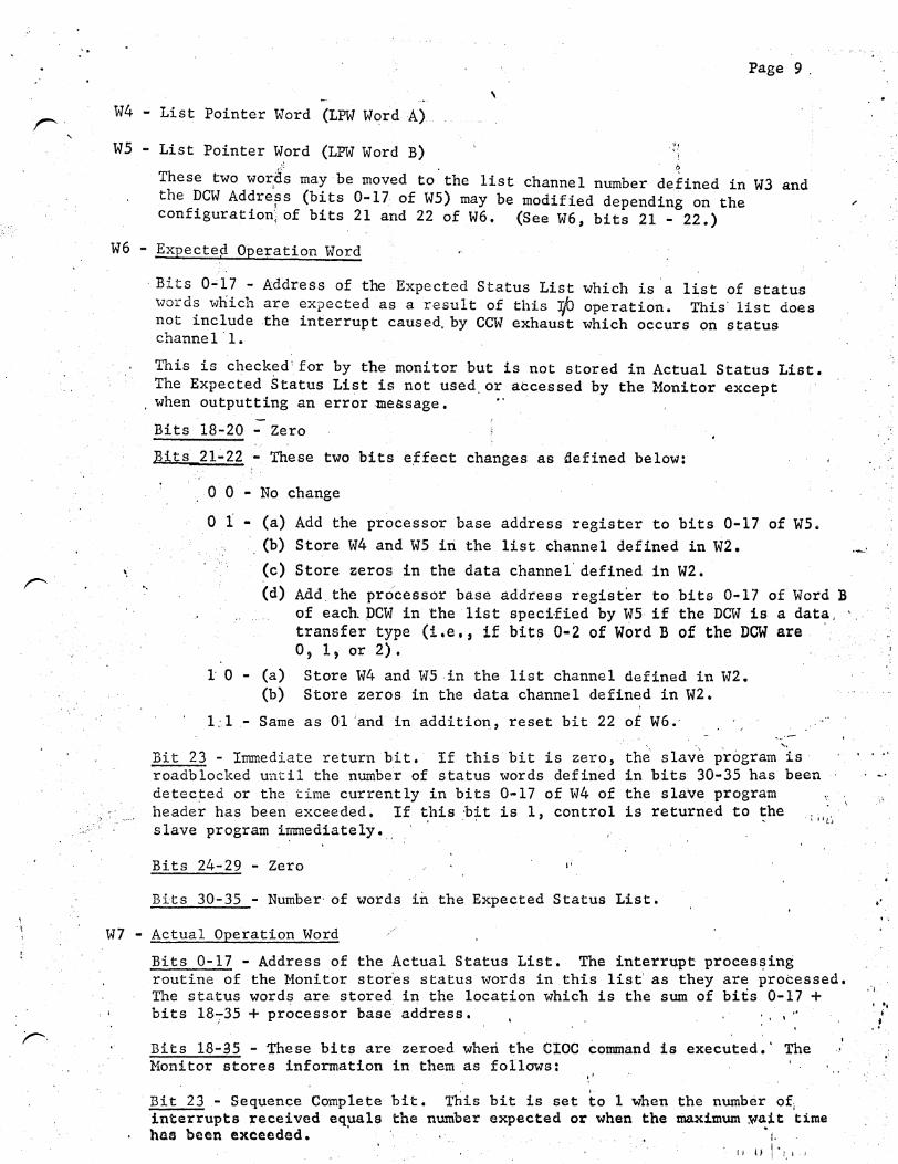
' W4 - List Pointer Word (LPW Word A)
ws List Pointer Word (LPW Word B) A b
These two wor;ii.s may be moved to. the list channel number defined in W3 and the DCW Addre~s (bits 0-17 of WS) may be modified depending on the configuration·; of bits 21 and 22 of W6. (See W6, bits 21 22.)
W6 - Expectep Operation Word
..
·Bits 0..;17 - Address of the Expected Status List which is ·a l~st of status word~ which are expected as a result· of this r/J operation. This' list does not ~nclude the interrupt caused. by CCW exhaust which occurs on status channel ·1.
This is checked'for by the monitor but is not stored in Actual Status List. The Expected Status Li~t is not used.or accessed by the Monitor except when outputting an error message. ·
Bits 18-20 - Zero
Bits 21.:.22 - These two bits e,ffect changes as defined below:
0 0 No change
0 1 - (a) Add the processor base address register to bits 0-17 of W5. · (b) Store W4 and W5 iri the list channel defined in W2.
(c) Store zeros in the data channel' defined in W2. ·-·
(d) Add. the processor base address register to bits 0-17 of Word B of each. ,DCW in the ·list speci·fied by WS if the DCW is a data. ' .. · transfer type (i.e., if bits 0-2 of Word B of the DCW are 0, 1, or 2).
l' 0 (a) Store W4 and W5 in the list channel defined in W2. (b) Store zeros in the data channel defined in W2.
1 ;.1 - Same as 01 ;and in additio11, reset bit 22 of W6 •· ...
.·.
Bit 23 - Immediate return bit. If thiS bit is zero, th~· slav·e program 'is roadblocked until the number of status words defined in bits 30-35 has been
' ...
\'. detec~ed or the time currently in bits 0-17 of W4 of the slave program header has been exceeded. If this ·b~t is 1, control is returned to the . i i•ti
slave program i~ediately.
Bits 24-29 Zero
Bits 30-35 - Number· of words in the Expected Status List.
W7 - Actual Operation Word /
. '
Bits 0-17 - Address of the Actual Status List. The interrupt proees~ing routine of the Monitor stor'es status words in this list' as they are processed. The status words are stored in the location which is the sum of bits 0-17 + bits 18735 +processor b~s~ address. . , ~
Bits 18-35 - These bits are zeroed wheri the CIOC command is executed.' The ., Monitor stores information in them as follows: ...
· Bit 23 - Sequence Complete bit. This bit is set to 1 when the number of; interrupts received equals the number expected or when the maximum ~ait time has been exceeded. · • 1.
'. II if I'!.' '
. . ...
... i
• ·, ..
Page 10
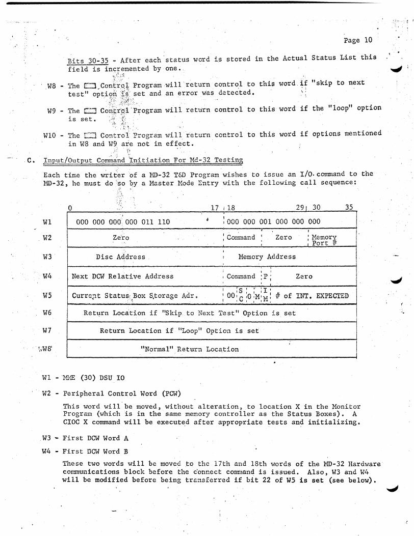
Bits 30-35 - After each status word is stored in the Actual Status List this field is inc:;emented by one.
""'t; ~:~. ;.·~
.W8 - The 0 Control; Program will return control to this word if "skip to next test" option f.~' set and an error was detec'ted. ':
~t~.!- .-:>:-:~.: .~:. . . W9- The c:! Co!i~rpl'P~ogram will return control to this word if the "loop" option
is set. · ii ., . ~ . .: '
WlO - The r~:J Control Program will return control to this word if options mentioned in WS and W9 are not in effect.
,·· \'•
C. ~put/Output Co~a.nd tniti ation For Md-32 Testing .;
Each time the writer 'of a 'MD-32 T&D Program wishes to issue an I/O. connnand to the MD-32, he must do '·so by a Master Mode Entry v7ith the following call sequence:
0 ., 17 I 18 291 30 35 ·;
Wl 000 000 000,000 011 110 6 :000 000 001 000 000 000
I;.. ' d I
Zero , vomman ' Zero ; Memor~ ' 1 Port ~ I
. W2
' W3 Disc Address I Memory Address ' i ' ' Next DCW Relative Address , Command ;P; Zero W4 ' ' I s I ,. 'I'
CurreJlt Status.: Box S,torage Adr. I ' I I I 41 of INT. EXPECTED .' . ·~· :oo:c:O;M:M: W5
W6 Return Location if "Skip. to Next Test" Option is set i
W7 Return Location if 11Loop 11 Option is set I I
'
I "Normal" Return Loca,tion · · r.¥W8'
Wl - 'MHE (30) DSU IO
W2 Peripheral Control Word (PCW)
This word will be moved, without alteration, to location X in the Monitor Program (which is in the same memory controller as the Status Boxes). A CIOC X command will be executed after appropriate tests and initializing •
. W3 - First DCW Word A
W4 - First DCW Word B
These two words will be moved to the 17th and 18th words of the MD-32 Hardware communications block before the c'onnect command is issued. Also, v13 and W4 will be modified before being tre:.nsferred if bit 22 of W5 is set (see below).
::··-·· ( !
..
.. Page 11
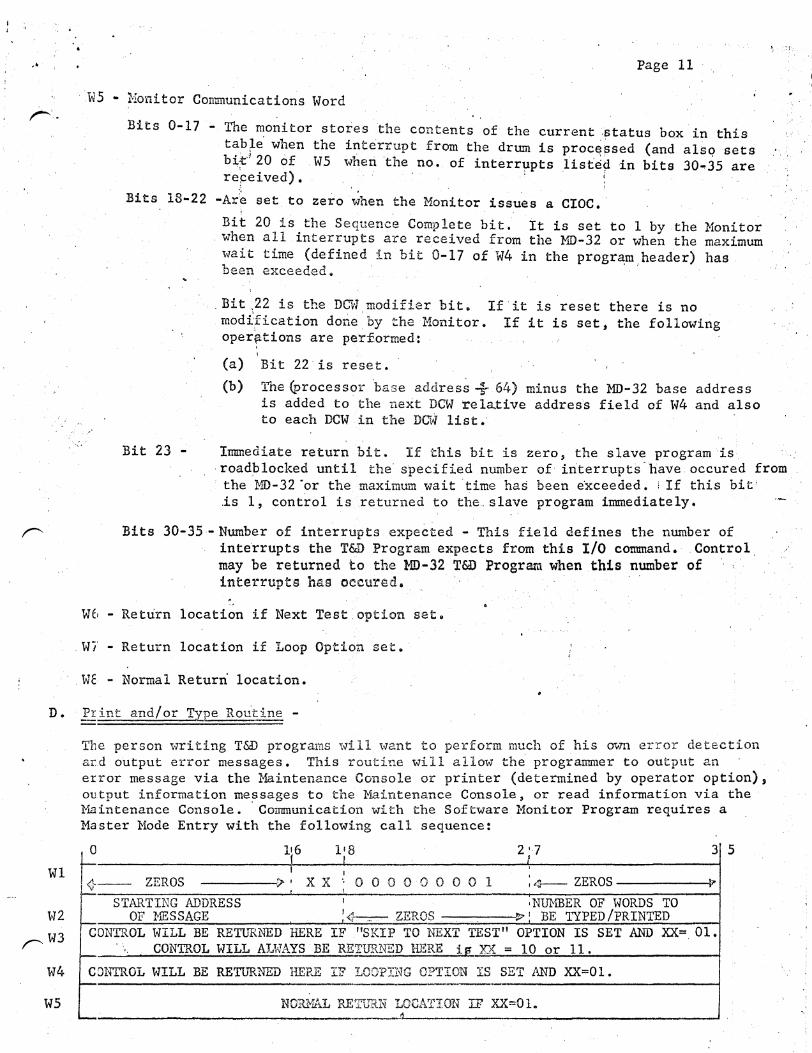
W5 .. f1onitor Communications Word
Bits 0-17 ;.. The ~onitor stores the contents of the current .status box.in this tab~e when the interrupt from the drum is proce,~sed (and alsq sets b:i,:e 20 6£ . W5 wheri 'the no. of interq1pts listed in bits 30-35 are repeived). . . · . . ' i
~ . Bits 18·22 -Ar'e set to zero when the Monitor issues a CIOC •.
Bit 20 is the Sequence Complete bit. It is set to 1 by the Monitor . when all interrupts are received from the MD-32 or when the maximum '"ait time (defined in bit 0-17 of W4 in the progrB;m,header) has been exceeded.
· .. Bit;22 is the DCW modifier bit• If'it is reset there is no modification done.by the Monitor. If it is set, the following oper{ltions are performed:
' ' (a) Bit 22'is reset.
(b) The (processor ·base addres~ ..f 64) minus the MD-32 base address is added to the next DCW relative address field of W4 and also to each DCW in the DCW list.·
1.':
•...
Bit 23 Immediate return bit. If this bit is zero, the slave program is ·roadblocked until the· specified number of in'terrupts -have occured from ·the MD-32 ·or the maximum wait ·time has been e'xceeded. i If this bit· .is 1, control is returned to the .. slave program immediately.
Bits 30-35-Number of interrupts expected- This field defines the number of inte·rrupts the T&D Progral!l expects from this I/O command. . Control may be returned to the MD-32 T&D Program when this number of interrupts has oc.cured.
,,
W6- Return location if Next Test.option set •
. Wi' - Return location if Loop Optiop. set.
· . We - Normal Return' location.
D. Print and/or T.ype Routine -
Wl
W2
rw3
W4
W5
The person writing TW programs will want to perform much of his own error detection ar.d output error messages. This routine will allo-tv the programmer to output an error message via the Maintenance Console or printer (determined by operator option), output information me~sages to the Maintenance Console, or read information via the Maintenance Console. Communication with the Software Monitor Program requires a Master Mode Entry with the following call sequence:
0 1(6 118 2 '·7 3
~-'t J
I ' I
;4---- ZEROS ZEROS r..o XX •, 0 0 0 0 0 0 0 0 1 I
5
STARTING ADDRESS I •NUMBER OF WORDS TO OF MESSAGE '~ZEROS ,_., BE TYPED/PRINTED
CONTROL WILL BE RETURNED HERE IF . "SKIP TO NEXT TEST" OPTION IS SET AND XX=. 01. CONTROL WILL AI .. WAYS BE RETTJRNED HERE ie- XX = 10 or 11.
CONTROL WILL BE RETURNED HERE IF LOOPTI'IG OPTION IS SET AND XX=Ol.
NORMAL RETURN LOCATION IF XX=Ol. ~
vn MME TYPR (XX=Ol) or TYPEW (XX=lO) or TYPER (XX=ll). f., r''_
NOTE: MHE TYPRI- The message \·Jill be· typed or printed according to the type or print optiqn.· Wh~n this routine is entered, all of. the error options are tested by the ·Software Honitor Program (looped, 1Skip, Bypass error typeout, Halt after err,or, etc.). The programmer has the responsibility of the message format to be typed or printed. Tne control program will assume the message is the typewriter. If the print option is in effect; the control program will interrogate the nThuber of successive carriage returns and slew that number of lines after pri?ting.
NI:1E TYPEH - This entry vJill output a message on the Maintenance Console, ~nly. None of the error options are interrogated and control will always be returned
'' I
to W3.
1:-iME TY'PER - This entry is provide-d to enable a program to issue a MainteiJ.ance Console read command. Control is returned to Slave Program after Console · Termination with status to A-register.
·. W2 • Bits 0-17 contain the starting address of the message to be typed or" the input. area to be typed. into. Tl}e message or area cannot be "scattered" in mem.ory as only one DQv will be used for the type connect command.
. -· ' . . '',
~or,.
' •, ' j
Bits 27-35 contain the binary count of .the number of words to be typed .out or · typed into. The maximThu nThuber of words is 777 octal. · .
. W3 - Control will always be returned to this word in the case of an MME TY~EW' or MME TYPER. If the entry is a ~1E TYPER, control will be returned to this word if the "skip to next test" option is set. . ' · :-' .
\•, ..JJ ~--·~
V/4 - Control will be returned to this word if the entry is ':A MME TYPR and the "loop" option is set.
E • READ QUEUE COUNTERS Al\'D SECONDARY HAILBOXRS .ROUTINES
TI1e purpose of this routi~e is to allow the IOC T&D Program to read the secondary . mailboxes, interrupt queue counters, and duplicate interrupt queue counters • . Communication with the Software Monitor Program-requires a Master Mode Entry with the following call sequence.
Wl
W2
W3
W5
\<16
W7
W8
W9
·o
I
4
<.':1 ...;,;
-:.j
-'·
""'
<
..::::
~
<.
·'\ I I I
ZEROS > I 1 I
' PUB -i I I I ADDRESS I ~
1~8 3· 5 I I I I
I
0 0 ' 0 0 0 0 0 0 0 0 1 I ZEROS ' '
IOC I I
ADDR. I I
ZEROS -ZEROS
ZEROS ~
ZEROS ~
ZEROS
ZEROS
ZEROS ...
,, '•
l

,.r-· Page 13
iH - MME RMAIL ~\, -.
l•f2 - Contains the Pyn number (Bits 12':' 15) and IOC number (Bits l6-17) of the queue counters and mffilboxes to be read. . .~· .. ~
'·
.K3-W9 - Contain zer~ upon entry. Upon exit, the T&D Control routine will place the fol~owing information in these words.
W3 . : INITIATION I I DUPLICATE
4 ZERO~ "; QUEUE CNTR I I 5riTIATION 1¢-- ZEROS I I UEUE CNTR
1 ; TERMINATION I DUPLICATE I
4 ZEROS ~: QUEUE CNTR 1+- Zeros .... I TERMINATION : QUEUE CNTR 1
W4
I SPECIAL I I DUPLICATE <1 ZEROS --r>; QUEUE
I I SPECIAL f4--:"- . ZEROS ~ CNTR I QUEUE CNTR
W5
'l CONTENTS OF SECONDARY MAILBOX 111 _Jl""
W6
W7 CONTENTS OF SECONDARY MAILBOX #2 I> .
W8 ~ CONTENTS OF SECONDARY MAILBOX #3 ,.
.4 CONTENTS OF SECONDARY MAILBOX 114 ..... .T W9
''
F • SET QUEUE COUNTER ROUTINE
The purpose o·f this routine is to allow the IOC T&D Program to store the count he wishes in particular queue counter and its duplicate. It should be noted that the count given by the program will be placed in both the queue counter and .. its duplicate. Communication with the Software Monitor Program requires a.Master Mode Entry_.with tl)e following call· sequence. · "· \\ ' -' '·
/ '
..
0 1 1 5 I
11·8 ~~1 2t 217 I 3,1 0' 3r~· 3: 5 -· -· ..
I f ' . I '
.Wl I I I ..,;: ZEROS t> il 0' 1,.0 o ·o.o o o o o licq ZEROS· I
I I I
W2 I
I .:.:) ZEROS I XY z 1, 0 0 I COUNT I I I
Wl MME QCTRS
W2 - Contains the type of interrupt counter desired an4 the value to 'set the counter. -Bits 27-29 Type of interrupt counter to store value into.· Bit 27 Initiation Bit 28 Termination Bit 29 Special Bits 32-35 This value will
its duplicate.
..
' \I
' . ' ' be placed into the queue counter desired and
''
I .
.·,' • .I .. , ' . '
•.
Page 14 ·.
.•
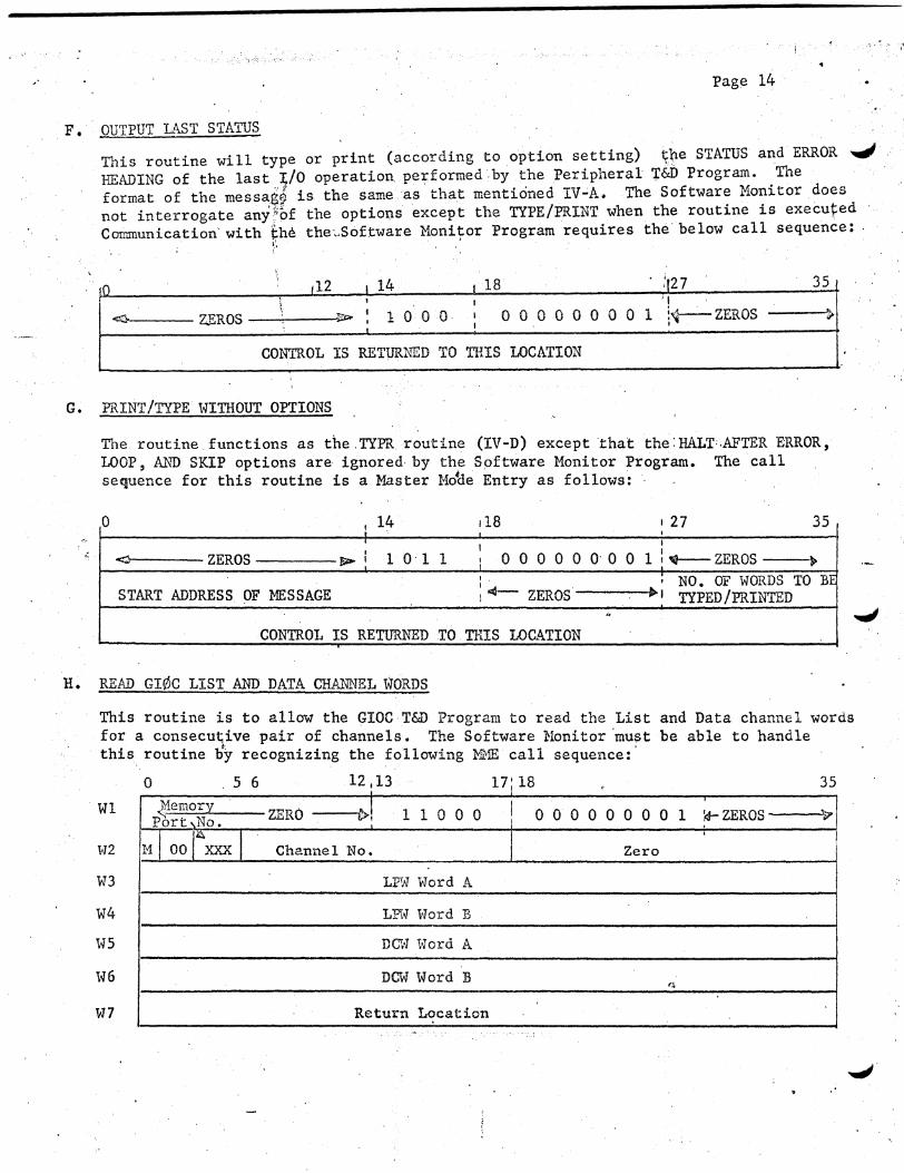
F. OUTPUT LAST STATUS
This routine will type or print (according to option setting) ~~e STATUS and ERROR ....,I HEADING of the last I,/0 operation performed~by the Peripheral ',!:&D Program. The format of the messa.s9 is the same ·as that mentioned IV..;A. The Software Monitor does not interrogate any~of the optio~s except the TYPE/PRINT when the routine is executed Communication· with ~he the·..-Software Monitor Program requires the· below call sequence: ·
' . ~:.
·so t12 I 14 1 18 35 'I
~:' ~"""'----ZEROS----.-.---~ : 1 0 0 Q. 0 0 0 0 0 0 0 0 1 :~ZEROS --~~
, I .
CONTROL IS RET'!JRNED TO THIS LOCATION
G ~ PRINT /TYPE WITHOUT OPTIONS
The. routine functions as the . TYPR /routine (lV -D) except 'that the: HALT'·AFTER ERROR, LOOP, AND SKIP options are ignored by the S9ftware Monitor Program. The call sequence for this routine is a Master Mo~e Entry as follows: ·
0 14 35 rl8 I 27 l I
I I
.<:) ZEROS I 1 0·1 1 o o o o o o· o o 1 l 'If-- ZEROS ~I I ~
I. I NO. OF WORDS TO BE ; ,.._ ZEROS. .,.,
START ADDRESS OF MESSAGE TYPED/PRINTED "
CONTROL IS RETURNED TO . THIS LOCATION
H. READ GI¢C LIST AND DATA CHANNEL W'ORDS
This routine is to allow the GIOC T&D Program to read the List and Data channel words for a consecu~ive pair of channels. The Software }1onitor 'must be able to handle this routine by recognizing the following MME call sequence:'
Wl
W2
W3
W4
W5
W6
W7
0 56 12113 17'18 35 l <
~emory ZERO ~r 1 1 0 0 0 I 0 0 0 0 0 0 0 0 Port,No. I 1 ~ZEROS v '
M I 00 r~xxx I J '
Channel No. Zero
LPTJJ Word A
LPW Word B
DC"d \vord A
DCW Word B ~
Return Location ..... . "

,·
...
Page 15
Bit 0 of word 2 is the Modification control bit. If bit 0 is zero, the words are transferred from the channel mailbox locations to W3, 4, 5, and 6 without' modification.
If bit 0 is o11e,, the processor base register is subtracted from LPW Word B before it is s'tored and· also from DCW Word B if the DCW is a data transfer type. The words in the chanriel locations remain unchanged.
The Software M~nitor will mask off bit 17 of the channel number in W2 to ascertain that a List Pointer pair will always be placed in W3 and W4.
' I. gT GI0C LIST AND DATA CHANi\IEL WORDS
· This MME is similar to. the one to read the channel words except that data is transferred from W3, W4, W5, and W6 to the channel mailbox locations •. The address. portion of the MME word is 2510.
If bit 0 of W2 is one, the_processor base address register is added to the address fields by the Software Monitor before the words are stored. The words in the call sequence remain unchanged.
J. .Q!!rPUT LAST GI0C STATUS
Wl
.W2
W3
This routine will type or print (according to option setting) the STATUS and ERROR HEADING of the last I/O operation performed by the GI0C T&D Program. The format . of this message is the same.as the GIOC error message mentioned in: IV- A. The Software Monitor does not interr.ogat-e.any of-.the.options except the Type/Print when this routine is executed. Communication with the Software Monitor Program requires tha following call Sequence: ·
0 12 13 17 18 27 35 ..--
~- ZERO •. 1 1 1 0 0 o o o ·o o o o o: ] <IE ZERO ., , 1--
Mask Address .. A . ZERO -... . CONTROL IS RETURNED TO THIS LOCATION -K. @ill 1'-ID-32 STATUS BOXES
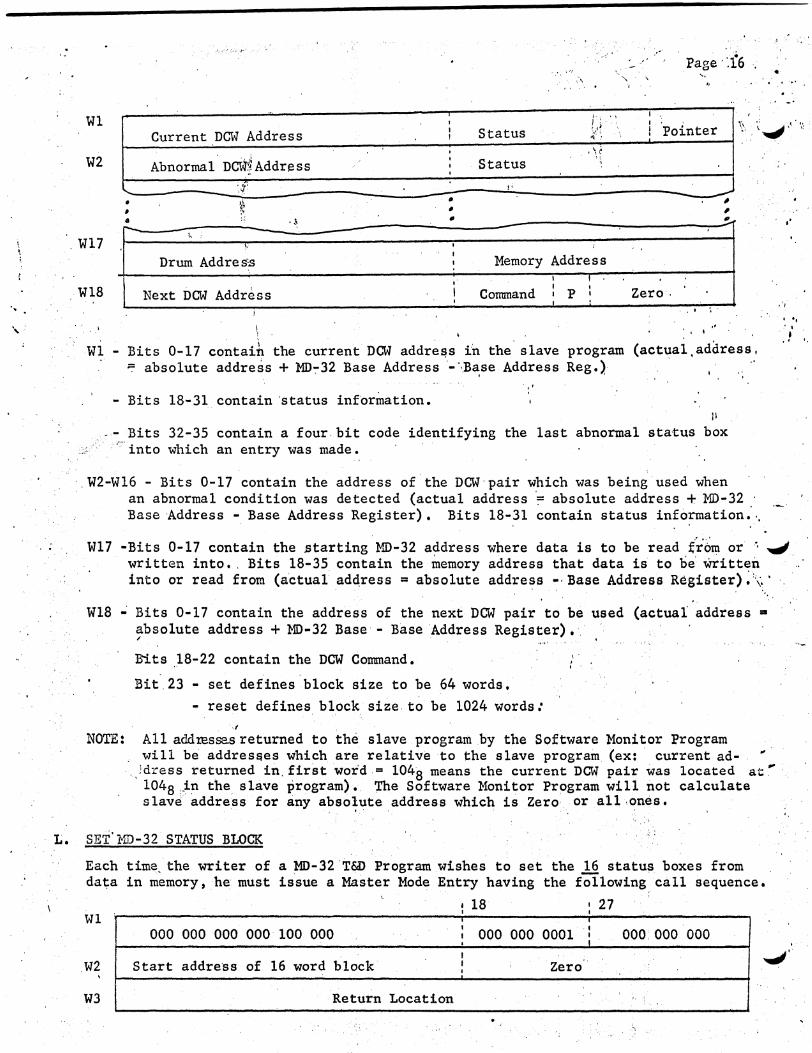
Eaeh time the writer of a MD-32 T&D Program wishes to read the 18 status Boxes (16 status boxes and 1st DCW pair), he must do so by a Master Mode Entry with the fo:~lowing call sequence.
Wl 000 000 000 000 011 111 I 000 000 001 000 000 000 I • I.
Start Address for 18 Word Block I Zero (Mod 2)
I I
W3 Return Location
Ul MME (31) RBLOK.
W2 - Bits 0-17 contain the starting location i~ the slave program where the J& word block is to be stored into. This starting address must be even. The block will be stored 'by, the Software Monitor as shown on the following page. 0
.... ··
' ,.
. . '. ·• ~.·
-· :.- .. Page · ·.f6 . •. ·. ,~, "' .... · ....
Wl
W2
. W17
Wl8
• ' • -
Current DCW Address
Abnormal. nci71 Address
·~ '•
.•
Drum Addres~ ',
Next DCW Address
• • "
I
I I
I
I
Status
Status
I
Memory Address I ' Command I p I I I
'.
Zero.
# # , ..
I .. ,·, I
' ..
Wl Bits 0-17 contaift the current DCW address in the slave program (actual,address, :: absolute address + M1>":"32 Base Address ·-··.Base Address Reg.)· ..
·,·
Bits 18-31 contain 'status information.
Bits 32-35 contain a four.bit code identifying the last abnormal sta-tus box :::;. ·"":into which an entry was made •
. W2-Wl6- Bits 0-17 contain the address of.the DCW·pair which was being used when an abnormal condition was detected (actual address ':= absolute address + MD-32 · Base ·Address - Base Address Register). Bits 18-31 contain status information:·.
• 'I .' .. . ' '·
Wl7 -Bits 0-17 contain the starting MD-32 address where data is to be read £r'6m or · . .J written into •. Bits 18-35 contain the memory address that data is to be· written .. into or read from (a.ctual ad~ress = absolute address -·Base Address Register)~\.·
• .. .. Wl8- Bits 0-17 contain the address of the nextDCW pair to be used (actual address •
absolute address + MD-32 Base - Base 'Address Register) •. · ~
Bits 18-22 contain the DCW Command.
Bit.23 set defines block size to be 64 words.
reset defines block size. to be 1024 words: . ·I ,
'. I I
NOTE: All addtesse.s returned to the slave program by the Software Monitor Program will be addresaes which are relative to the slave program (ex: · current ad- "
·.)dress returned in. first word = 104a means the current DCW pair was located at~ · 1048 ,_in the slave program). ',t'he Software Monitor Program will not calculate slave address for any absolute address which is Zero· or all,ones.
' , . . .
L. SET'MD-32 STATUS BLOCK
Each time. the writer of a MD-32 'T&D Program .wishes to set the 16 status boxes from. dat::a in memory, he must issue a Master Mode Entry having the following. call sequence.
18 27 Wl
000 000 000 000 100 000 I
000 000 0001 ·I ooo:ooo 000 I I
I I .
I
Start addre·ss of 16 word block I Zero •' I ., .W2
W3 Return Location '• ' ..
,.,

..
Page 17
.:W:. - l1ME (32) SBLOK
W~~ - Bits 0-17 conta~n the starting address of a 16 word block ~P be stored into the 16 status ;~Qxes. Address must be even.
:. ~~: j;;;'[
NOTE: The address )pbrtions of the status block (bits 0-17) is set to zero or all ones if the programmer w~shes to determine the.entries placed in the status block by the }1D,:-32.~ The Software Monitor Program converts all a.ddress in the block to;slave address when it receives a MME RBLOK if the addresses are not zero .~or all ones. '
r.· ___ .,,
M. RFLINQUIS E CONTROL FOR MD-32 T&D PROGRAM l
TI .. is routine is used\ by the Mo-32 T&D Programs to give control back to the Software Mc•nitor until a certain number of interrupt::s has occurred. The call sequence for tt.is ~outine is as follows:
~2 '. 3t 0 18 27
'Kl <J- Zeros ~ 100-·001 000 000 001 <f Zeros £if
\\'2 A. Zeros .- Number of _,.. .... .. Interrupts
Control is Returned to this Location "' ,Cf
... '
~- ' . ·.I
When thi.::; routine is executed, the Software Monitor Program will not return .1 control to the MD-32 T&D Program until the number of interrupts received is equal to. or greater than the number in bits 32 - · 35 of W2 or until the maximum wait time for the interrupts (determined by bits 0 J7 of W4 of the PROGRAM HEADER) has elapsed.
. . __ .....
, . •
' '., ; ; ~ .. ...
. . . 1:
' . . ·,
. •'
•'
I'
Page 18 ..
.-.~~.
v. I
SYSTEM CONFIGURATION CHANGES ... The T&D Program operating under co,ntrol of the Software Monitor Prqgram will have to have complete control of tn~e Peripheral, IOC, GIOC, or MD-32 ,;.t~ is testing. The Software. Monitor Prograk\will have to. delete a peripheral''irom its system configuration when an on-line Peripheral T&D Program is calle'd into memory. If the T&D Program is an IOC 'or a GIOC T&D Program, the Softwar:.~ Monitor ml.S t delete the entire IOC or GIOC from its system configuration. ··
i
The Product Service man should have the capability to delete and add to the Software Monitor's system configu~ation through the maintenance/console.
' ·--- VI. RETURN TO T&D PROGRAM1 AFTER I/0 REQUEST -·The Software Monitor will return contro1
to a T&D Program in tqe following manner after the T&D Program has issued a MME I/0:
A. IMMEDIATE RETURN - The T& D Program may set a bit in a MME I/O which means it wants returns to the program immediately after the Software Monitor has issued the CIOC command. This feature will be used sparingly
1): ·by the T&D Programs and only when it is necessary to test certain functions.
B. NUMBER OF EXPECTED INTERRUPTS IS RECEIVED - Each I/O command will contain the number of interrupts that is expected from the execution
· .. ··of that I/0 command. The Software Monitor may r.eturn control to the T&D Program when the number of interrupts received is equal to or
(·'.
greater than the number expected. .,/ .
C. MAXIMUM WAIT TIME. FOR INtERRUPT HAS ELAPSED - The Software Monitor Program may return~control to the T&D Program if the expected interrrupts have not occurred, but the maximum wait time has elapsed. This condition implies that an interrupt is "missing", and the Software Monitor should output a message to the Product Service man for this condition.
VII. ·OPERATOR OPTIONS - Switch Control - Primary option control is'maintained by usi~g th~-36 toggle switches on the processor maintenance panel. Control of certain optio~~ may be transferred to the maintenance console by setting switch 24 true {up). ~ee section 8 for console option).
A. ERROR OUTPUTS - Error messages may be typed on the maintenance console printed on a high-speed printer, or they may be suppressed. Switch 34 true causes output suppression; switch 34 false allows output· as specified by switch 26. For console typeout switch 26 must be false; foc printed output switch 26 must be true. (Console control words - TYPE/ PRINT/ BYPASS),
B. HALT/RUN AFTER ERRORS - When an error typeout occurs, it may be desirable to halt further I/0 operations fromthe T&D Program to allow operator action before subsequent tests. This option is pro\rided by us·e of IH·lit<::h JS. A hdt after typGo,ut will occur if switch 35 is false; no stop will occur if true. To proceed and halt at the next error, toggle ~ switch 35 true then false. To run without halts, set switch 35 true, (Console control words -HALT/RUN/GO).
. .

Page 19
C. SLOW RATE - A. delay between I/O operations may be usefu,.,l. If switch 30 is true, th~. Software Monitor Program will not return cp~ntrol to a T&D Program untf'l at· least .2 seconds after it normally woul:d have after an I /0, reques ~} (Console control words - FAST /SLOW.) '
?!
D. SKIP TO NEXT TEST - If a particular sequence of operations cannot be completed because of failure of a previous function, a skip to the next complete test may be effected by setting switch 31 true. ~his option is effective only follovTing a typeout. (Console control words -SKIP/NOSKIP.)
~ ' .
E. E!_START - An 1 error message miy be such that a res tart is necessary or desirable. It is possible to restart the T&D Program by setting switch 29 true. The'1 restart option is effective only after a, halt after typeout. (Console control words -START (RESTART)j TEST - PUB-).
F. T&D PROGRAM CUTOFF - If switch 32 is true (set), the software monitor will not return control to the T&D Program ·until the switch is reset.
CONFIG. INPUT ONS OLE CONTRO~
INT/TY.PE
9 Q 9 .9 y Q Q y Q Q 9 9 9 ff'Y 9 9 9 9 . 9 9 9 9 9 9 9 '9·
\TmST 9 9 .. 9': 9 9. ·9
.....
9 9 9 .~ 0 1 2.3 4 56 7 8.9 10 11.12 13 14 15 16 17 18 19 20 21 22•23 24 25 26 27 28 29 30 31 32 33 34 3~ . . ' . ' 1 .. . .
SLOW-----'-. I
.SKIP'------l
PROGRAM CUTOFF-----"
LOOP---------------~
SUPPRESS-----------------~
RUN:-----------------------4
PANEL SWITCH Su.t1MARY
_'Page 2C . -. •'
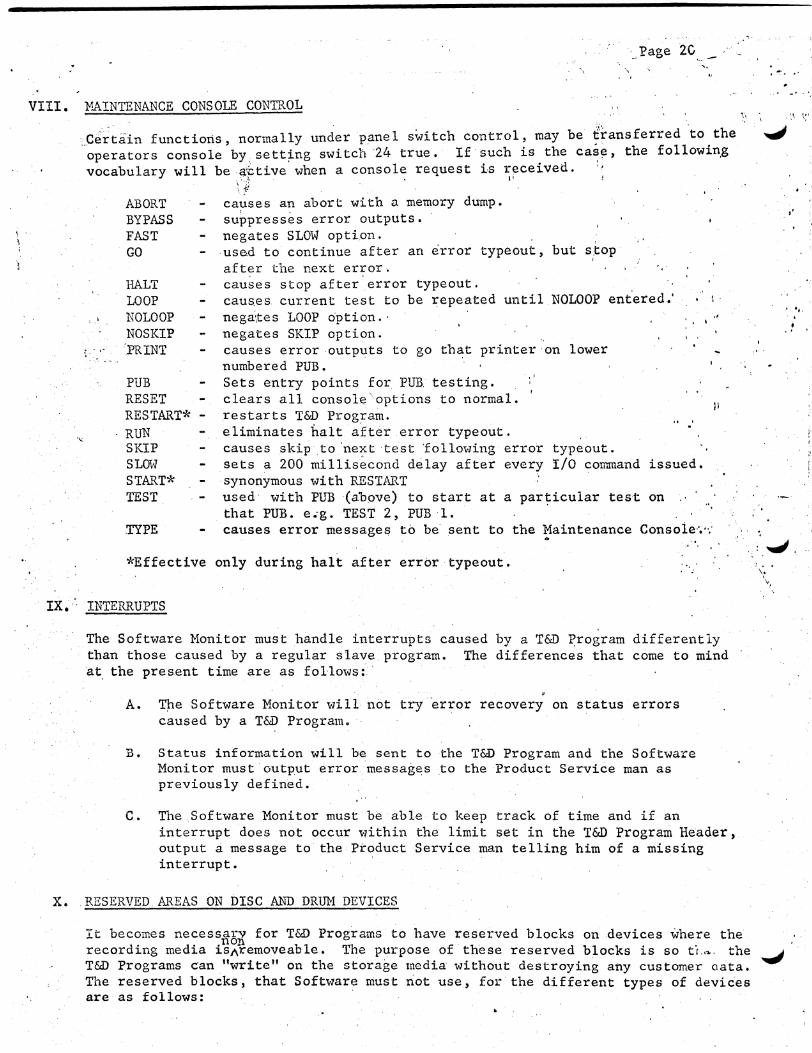
-· VIII. 1-'lAINTENANCE CONSOLE CONTROL
,_Certain functions, normally under pane 1 switch control, may be ~ransferred to the .,J operators console by_ sett~ng switch 24 true. If such is the case, the followin_g vocabulary will be a'f.:tive when a console request is ~rceived. ''
ABORT BYPASS FAST GO
HALT LOOP
causes an abort with a memory dump. suppresses error outputs. negates SLOW option. used to continue after an error typeout' but s,:top after the next error. causes stop after error typeout.
\'
,.
cau~es current test to be repeated until NOLOOP ent.ered.' nega\tes LOOP option. ·
·' ... ~ . I NOLOOP
NOS KIP : .. ·· PRINT
PUB RESET RESTART* -RUN SKIP SLOW START* TEST
,TYPE
negates SKIP option. causes error outputs to go that printer on lower numbered PUB. Sets entry points for PUR testing. clears all console'options to normal. restarts T&D Program. eliminates halt after error typeout.
·'
causes skip to 'next test following error typeout. sets a 200 millisecond delay after every I/0 command issued. synonymous with RESTART used- with PUB (above) to start at a par~icular test on that PUB. e.-g. TES.T 2, PUB 1. causes error message$ to be sent to the Maintenance Consoie·· ... ,.
• ..
: ..,J. *Effective only during halt after error typeout. '•,
IX.· INTERRUPTS
The Software Monitor must handle interrupts caused by a T&D :f>rogram differently than those caused by a regular slave program. The differences that come to mind at the present time are as follows: ·
A. TJ:le Software Monitor will not try error recovery on status errors caused by a T&D Program.
B. Status information will be sent to the T&D Program and the Software Monitor must output error messages to the Product Service man as previously defined.
C. The Software Monitor must be able to keep track of time and if an interrupt does not occur within the limit set in the T&D Program Header, output a message to the Product Service man telling him of a missing interrupt. ·
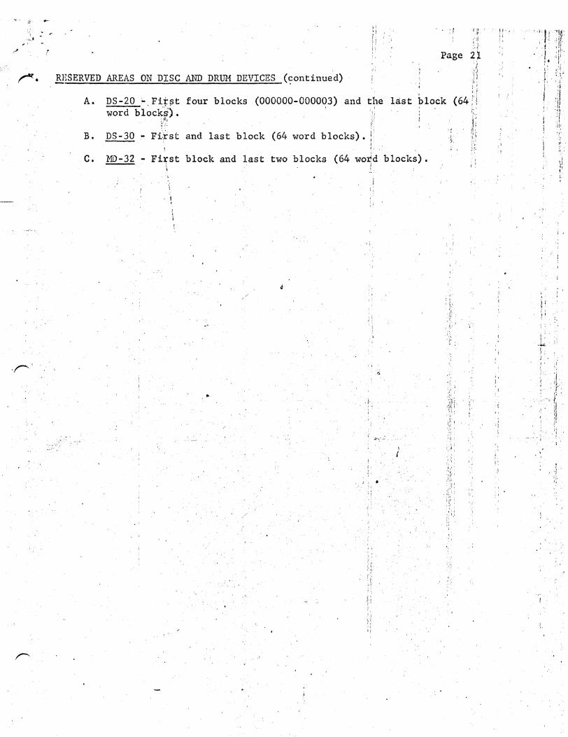
X. RESERVED AREAS ON DISC AND DRU}l DEVICES
It becomes necess~6l for T&D Programs to have reserved blocks on devices where the recording media isl\removeable. The purpose of these reserved blocks is so ti .. -,.. the .._1 T&D Programs can "write" on the storage media without destroying any customer oata. The reserved blocks, that Software must not use, for the different types of devices are as follows:
;,'·
-.: .. ,.
~. RESERVED AREAS ON DISC AND DRUM DEVICES (~ontinued)
• ' f il ,'i'i '.j
Page 2l ' ,.
•J 'II
A. DS-20 - First four blocks (OOOOOO-OOOOq3) and the last block (64 ;·; word bl~c~~~. ~·
/:· r; B. DS-30 Fi.;rst and last block (64 word blocks). !
C. MD-32- Fi:r;st block and last two blocks (64 wotd blocks). !
..
·:
"
't t \ . 1 ~~: S 'I
I·' '!f : ,;: I' •;/.
.. 'i'
p . )I'
f.
; '
l' : :.~·'
) .
. ·J.
