b.y.o.c. wah kit instructions …byocelectronics.com/wahinstructions.pdfif your op amp does not have...
TRANSCRIPT
B.Y.O.C. Wah Kit Instructions
www.buildyourownclone.com/wahV1.pdf forolder version instructions
Parts Checklist ......... ..page 2
Populating the Circuit Board ........ . ..page 3 - 7
Assembly ........ .....page 8 - 9
Wiring ......... ........page 10 - 11
Finish up ..............page 12
Schematic.............................................................page 13
The assebly portion of the instructions are very important.Please read them before building this kit.
Copyright 2007 Build Your Own Clone
Parts Checklist for Wah KitResistors:3 - ZERO resistors (single black band)1 - 1k (brown/black/red/gold)1 - 10k (brown/black/orange/gold)1 - 22k (red/red/orange/gold)1 - 100k (brown/black/yellow/gold)2 - 470k (yellow/purple/yellow/gold)2 - 2.2M (red/red/green/gold)Capacitors:2 - .01uf film (103)1 - .022uf film (223)1 - .1uf film (104)2 - .22uf film (224)1 - 4.7uf NON-POLARIZED (NP)aluminim electrolytic1 - 10uf aluminum electrolyticInductor:1 - halo replicaIC:1 - TL081 single op ampTransistors:2 - CV10805 or BC1082 - transistor socketsPotentiometers:1 - 100k ICAR taper pot with pinion gear and dust jacket1 - 1k trimmer (102)1 - 5k trimmer (502)2 - 100k trimmers (104)1 - 250k trimmer (254) or 200k trimmer (204)Hardware:1 - rocker enclosure w/ base plate, 4 screws,2 mounting screws, and rubber feet (not included indrop in kit)1 - wah kit circuit board1 - 3pdt footswitch1 - board mounted DC adaptor jack1 - ¼ stereo jack1 - ¼ mono jack1 - battery snap2 - wire tieshook-up wire
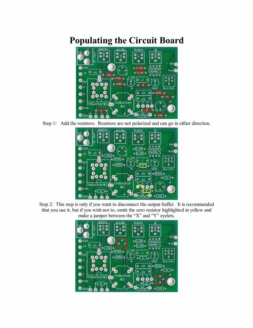
Populating the Circuit Board
Step 1: Add the resistors. Resistors are not polarized and can go in either direction.
Step 2: This step is only if you want to disconnect the output buffer. It is recommendedthat you use it, but if you wish not to, omitt the zero resistor highlighted in yellow and
make a jumper between the X and Y eyelets.
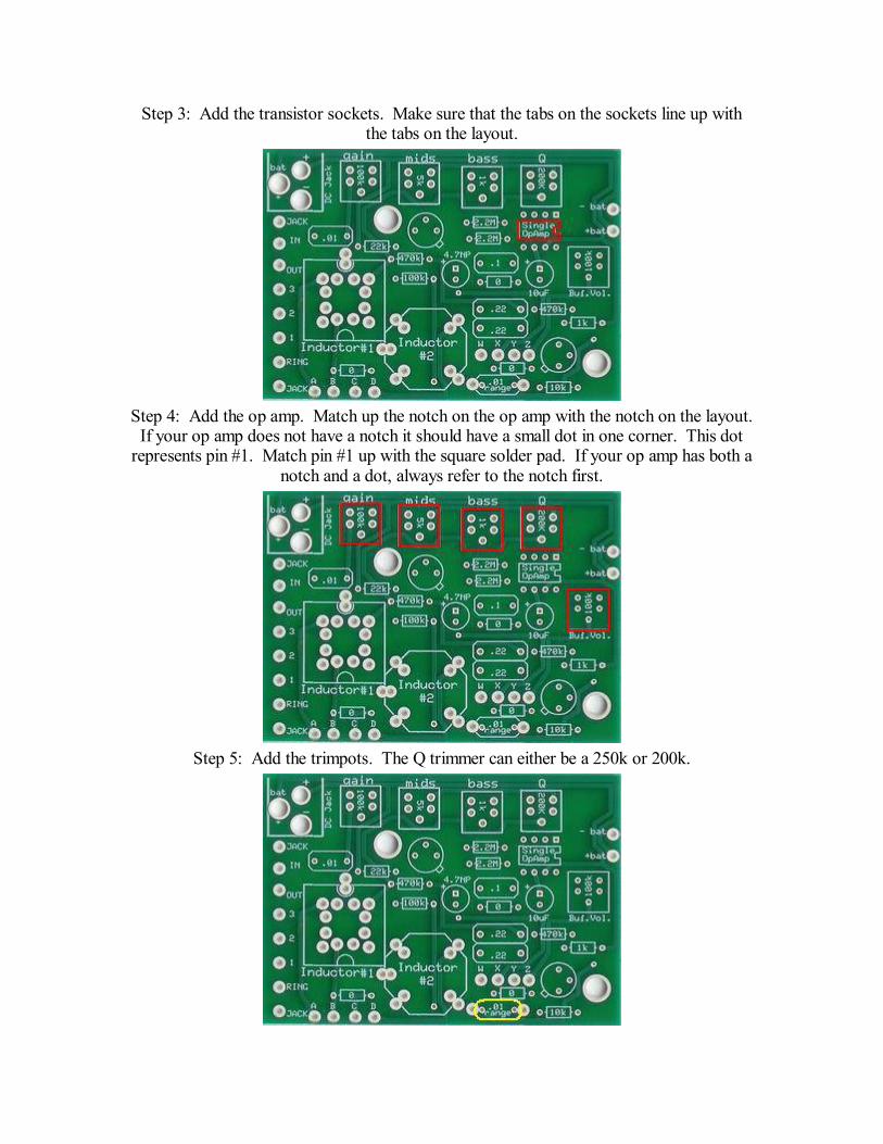
Step 3: Add the transistor sockets. Make sure that the tabs on the sockets line up withthe tabs on the layout.
Step 4: Add the op amp. Match up the notch on the op amp with the notch on the layout.If your op amp does not have a notch it should have a small dot in one corner. This dot
represents pin #1. Match pin #1 up with the square solder pad. If your op amp has both anotch and a dot, always refer to the notch first.
Step 5: Add the trimpots. The Q trimmer can either be a 250k or 200k.
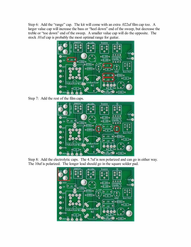
Step 6: Add the range cap. The kit will come with an extra .022uf film cap too. Alarger value cap will increase the bass or heel down end of the sweep, but decrease thetreble or toe down end of the sweep. A smaller value cap will do the opposite. Thestock .01uf cap is probably the most optimal range for guitar.
Step 7: Add the rest of the film caps.
Step 8: Add the electrolytic caps. The 4.7uf is non polarized and can go in either way.The 10uf is polarized. The longer lead should go in the square solder pad.
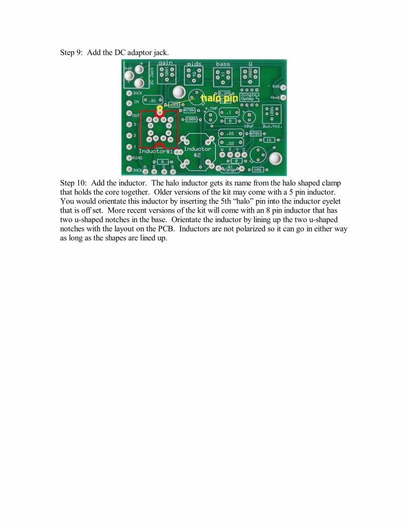
Step 9: Add the DC adaptor jack.
Step 10: Add the inductor. The halo inductor gets its name from the halo shaped clampthat holds the core together. Older versions of the kit may come with a 5 pin inductor.You would orientate this inductor by inserting the 5th halo pin into the inductor eyeletthat is off set. More recent versions of the kit will come with an 8 pin inductor that hastwo u-shaped notches in the base. Orientate the inductor by lining up the two u-shapednotches with the layout on the PCB. Inductors are not polarized so it can go in either wayas long as the shapes are lined up.
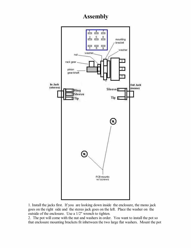
1. Install the jacks first. If you are looking down inside the enclosure, the mono jackgoes on the right side and the stereo jack goes on the left. Place the washer on theoutside of the enclosure. Use a 1/2" wrench to tighten.2. The pot will come with the nut and washers in order. You want to install the pot sothat enclosure mounting brackets fit inbetween the two large flat washers. Mount the pot
Assembly
so that the solder lugs are facing up if you are looking down into the enclosure.
IMPORTANT!!!!Once you have secured the pot, you will need to orientate the gears.You want to set the gears so that the pot does not come to a stop at either full heel downor at full toe down when you activate the footswitch. You need to set the gears so thatyou still have a little rotation left in the pot at either extreme of the sweep. I you don't setthe gear properly, you can and probably will break the shaft of the pot.
3. important!!!! The foot switch comes with two nuts, a serated washer, and a whiteplastic washer. You should remove the bottom nut and serated washer so that the base ofthe footswitch is flush against the inside wall of the enclosure. Only use the plastic washerand one nut on the outside of the enclosure to secure the footswitch. This is so that theplunger sticks up high enough to be actuated by the rocker platform.It does not matter which side you designate as the "leading edge" of the footswitch aslong as you orientate it so that the flat sides of the solder lugs are aligned in horizontalrows, not vertical columns.
4. Mount the circuit board using the mounting screws and washers that are supplied withthe enclosure. Orientate the circuit board so that the DC adaptor jack is lined up with theDC adaptor jack hole.
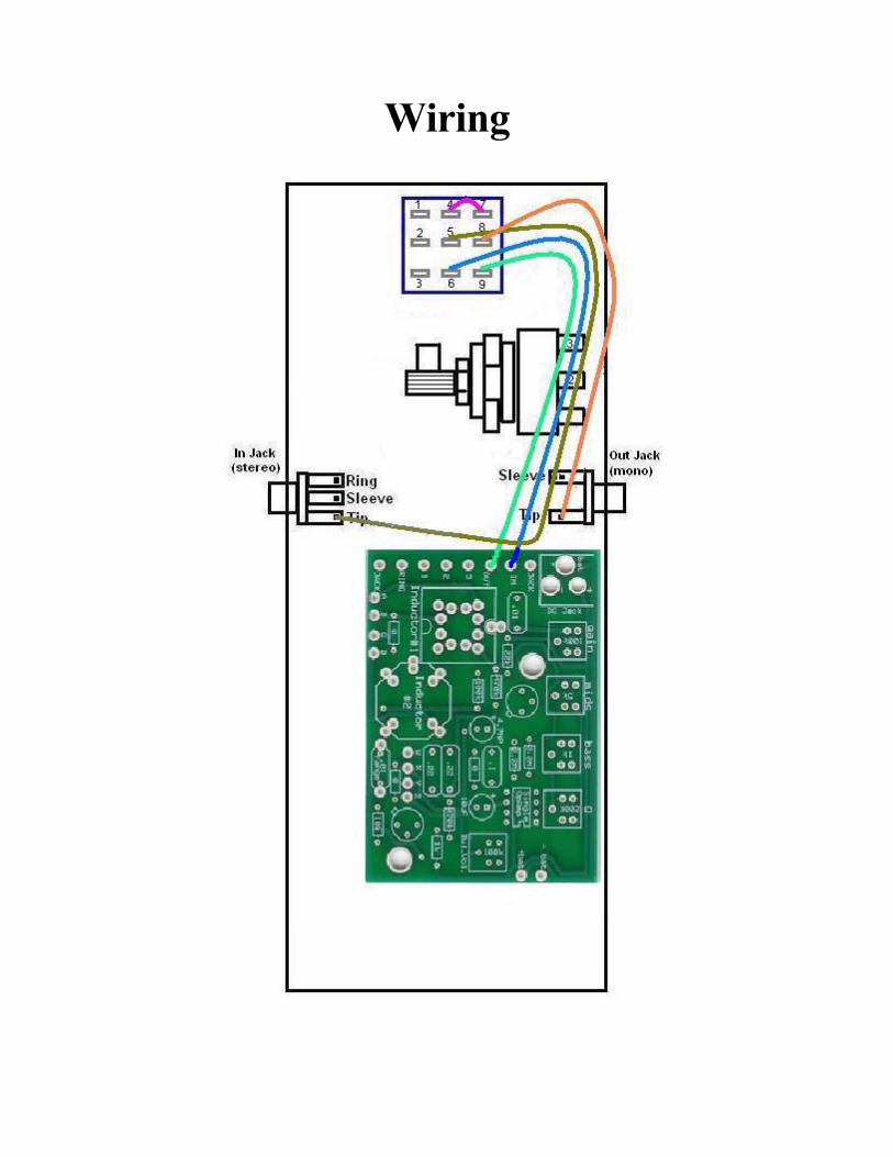
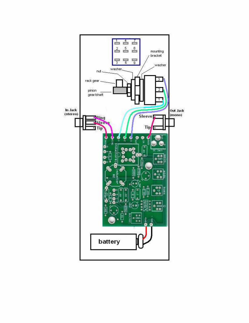
Wiring
Finishing Touches
Once you have finished wiring, use the cable ties to round up the longer wires.
Install the transistors into their sockets. Simply make sure the tab on the transistor is linedup with the tab on the socket.
Install the base of the enclosure with the 4 screws that came with your kit. Add the rubberbumper feet...unless you're a velcro person. If you've got any problems that you can'tfigure out yourself, visit board.buildyourownclone.com for technical support
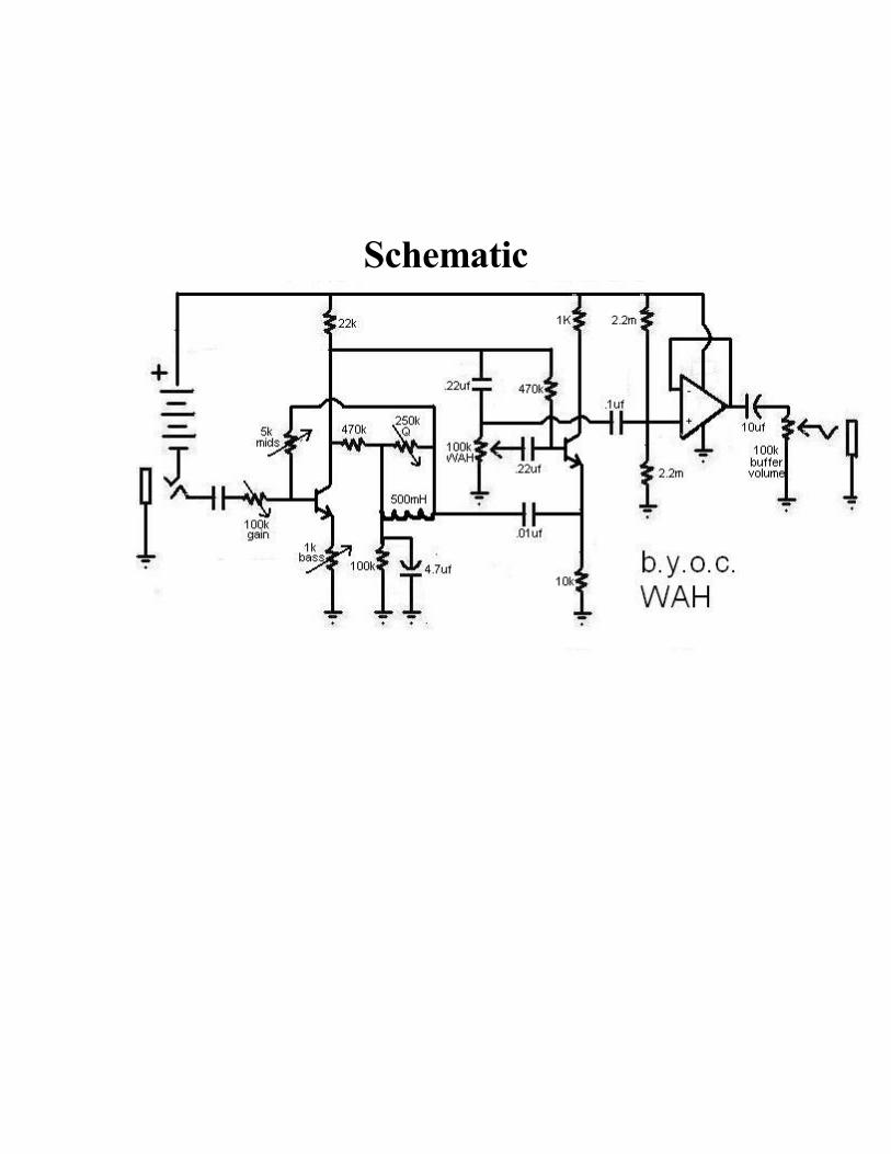
Schematic
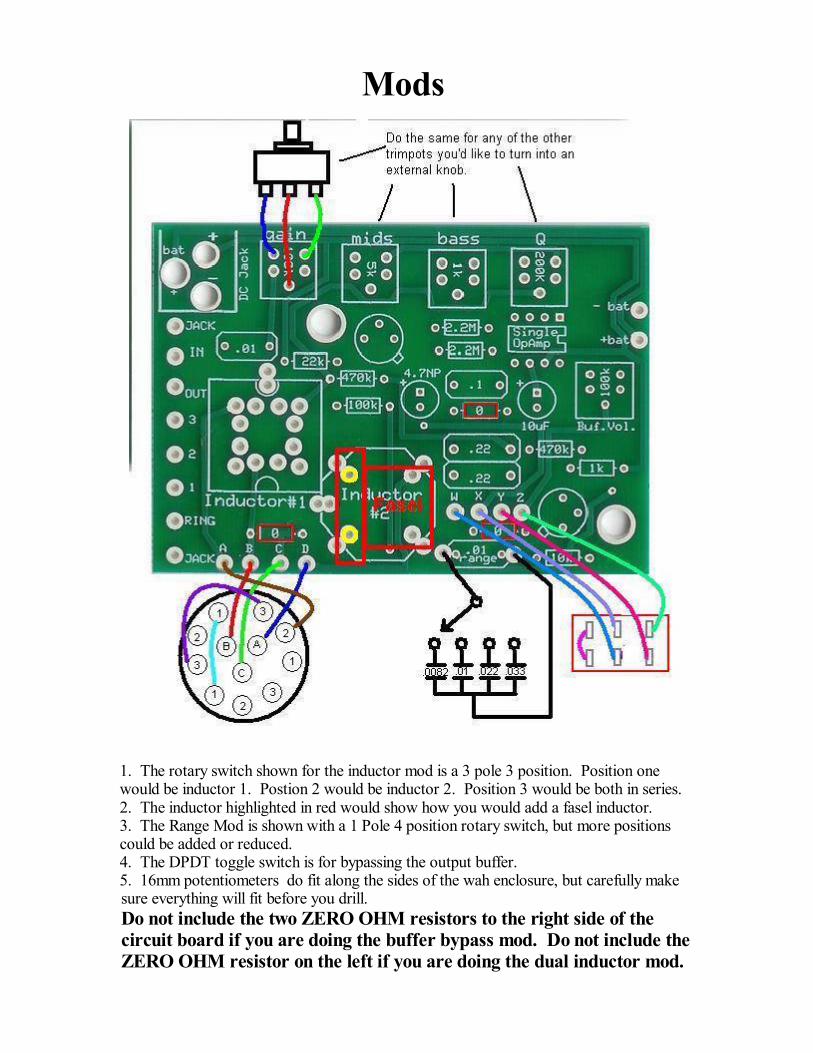
Mods
1. The rotary switch shown for the inductor mod is a 3 pole 3 position. Position onewould be inductor 1. Postion 2 would be inductor 2. Position 3 would be both in series.2. The inductor highlighted in red would show how you would add a fasel inductor.3. The Range Mod is shown with a 1 Pole 4 position rotary switch, but more positionscould be added or reduced.4. The DPDT toggle switch is for bypassing the output buffer.5. 16mm potentiometers do fit along the sides of the wah enclosure, but carefully make
ZERO OHM resistor on the left if you are doing the dual inductor mod.circuit board if you are doing the buffer bypass mod. Do not include theDo not include the two ZERO OHM resistors to the right side of thesure everything will fit before you drill.