bypass
TRANSCRIPT
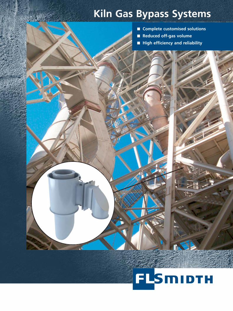
Kiln Gas Bypass Systems■ Complete customised solutions
■ Reduced off-gas volume
■ High efficiency and reliability
2
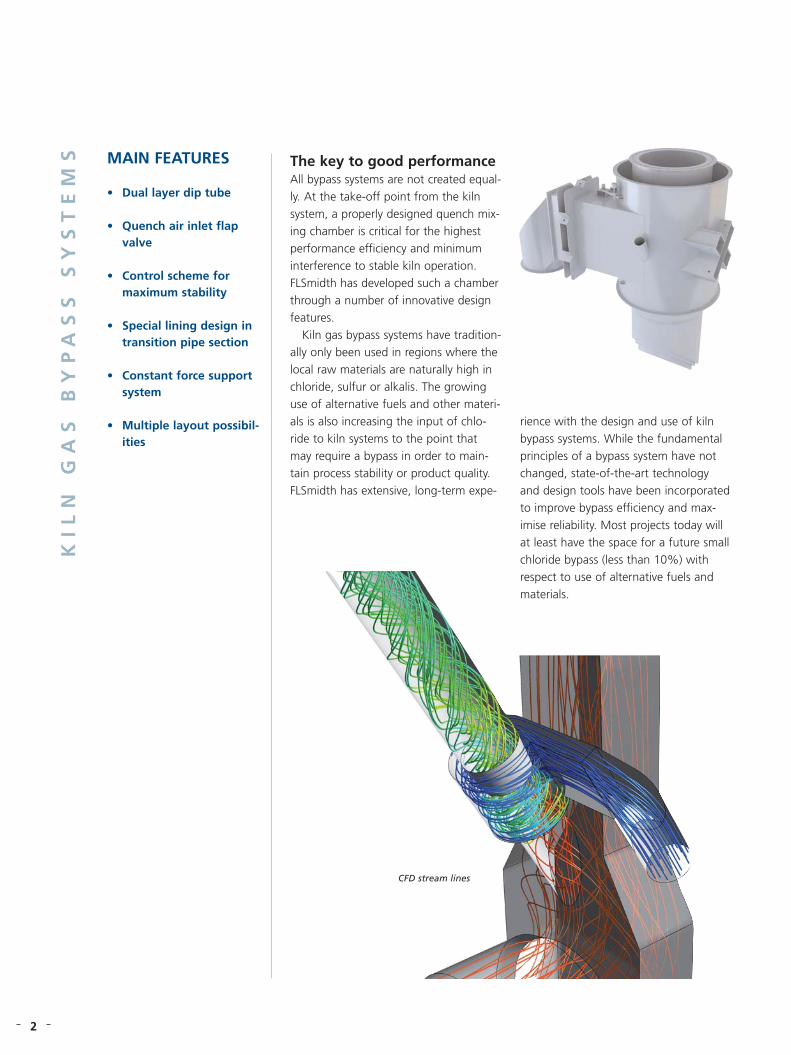
The key to good performanceAll bypass systems are not created equal-ly. At the take-off point from the kilnsystem, a properly designed quench mix-ing chamber is critical for the highestperformance efficiency and minimuminterference to stable kiln operation.FLSmidth has developed such a chamberthrough a number of innovative designfeatures.
Kiln gas bypass systems have tradition-ally only been used in regions where thelocal raw materials are naturally high inchloride, sulfur or alkalis. The growinguse of alternative fuels and other materi-als is also increasing the input of chlo-ride to kiln systems to the point thatmay require a bypass in order to main-tain process stability or product quality. FLSmidth has extensive, long-term expe-
MAIN FEATURES
• Dual layer dip tube
• Quench air inlet flapvalve
• Control scheme for maximum stability
• Special lining design intransition pipe section
• Constant force support system
• Multiple layout possibil-ities
KI
LN
G
AS
B
YP
AS
S
SY
ST
EM
S
rience with the design and use of kilnbypass systems. While the fundamentalprinciples of a bypass system have notchanged, state-of-the-art technologyand design tools have been incorporatedto improve bypass efficiency and max-imise reliability. Most projects today willat least have the space for a future smallchloride bypass (less than 10%) withrespect to use of alternative fuels andmaterials.
CFD stream lines

3
Dual layer dip tube A dip tube eliminates short-circuiting ofquench air directly to the outlet of thechamber. The dip tube ensures that thecomplete amount of quench air alwaysenters the gas swirl and mixes with thekiln gas.
As the dip tube is exposed to the coldquench air on the outside and the hotkiln gas on the inside, it is designed as adual cone system with a thermal insula-tion between the two steel sections. Thisensures long life time of the compo-nents. By keeping the inside hot, the riskof sticky build ups on the inside is min-imised.
Quench air inlet flap valveThe quench air inlet flap valve offers controlof the inlet velocity which enables the swirland the mixing of hot gas and cold air tobe optimised in a wide capacity span. Theflap valve is operated with an electrical lin-ear actuator.
System controlThe flow rates of the quench air andmixed gas after the quench chamber aremeasured continuously, so that the exactamount of gas extracted from the kilnsystem is known at all times. Controlloops will maintain flow stability so thatthe burning zone conditions of the kiln,
notably oxygen level and temperature,remain constant despite any operationaldisturbances.
Thermal insulation in transition pipeTo keep the surface of the transition pipebefore the quench chamber hot, it isequipped with a highly insulating liningdesign. This effectively reduces any poten-tial for build-up in this area.
Constant force support systemThe complete quench chamber is support-ed in a constant force spring system,which eliminates the need for a thermalexpansion joint on the transition pipe with-out stressing the structure of the riser duct.
Superior mixing of hot kiln gas andcold air Superior mixing of hot gas and cold airis created by the inlet flap and the diptube for a wide capacity span. Goodmixing is synonymous with an even tem-perature profile, which is one of theoverall criteria for optimum operation ofthe chamber. Local areas with high tem-peratures and increased stickiness ofdust are effectively avoided. The problem
of having surface areas exposed toeither higher or lower temperatures thananticipated, which could create structur-al failure on hot areas and severe con-densation on cold surfaces, is also elimi-nated.
Reduced off-gas volume Good mixing allows operation with highexit temperature from the mixing cham-ber so that a higher proportion of thecooling may be provided by waterinstead of air. In this way the volume ofgas to be treated by a filter installationand later discarded is greatly reduced.This can be translated into reducedinvestment and/or operational costs(kWh per kg gas removed) for thequench air blower, filter, bypass fan,ductwork, and stack.
Reduced risk of build ups in transi-tion pipe The special lining concept and norequirement of a thermal expansion jointin the transition pipe generates a hotand smooth surface which greatlyreduces the risk of getting build-ups inthis critical area.
CFD temperature map
Bypass system quench chamber

Our brochure makes no offers, representations or warranties (express or implied), and information and data contained in this brochure are for generalreference only and may change any time. Please contact us for specific information or data that may relate to your interests.
www.flsmidth.com
Up-to-date addresses of worldwidesubsidiaries and sales offices are available from our website
10-0
7-00
0 FL
Smid
th
DENMARKFLSmidth A/SVigerslev Allé 77 DK-2500 ValbyCopenhagenTel: +45 36 18 10 00Fax: +45 36 30 18 20E-mail: [email protected]
USAFLSmidth Inc.2040 Avenue CBethlehem, PA 18017-2188Tel: +1 610-264-6011Tel: +1 800-523-9482Fax: +1 610-264-6170E-mail: [email protected]
INDIAFLSmidth Private LimitedFLSmidth House 34, Egatoor, Kelambakkam (Rajiv Gandhi Salai – Chennai)Tamil Nadu – 603 103 Tel: +91-44-4748 1000Fax:+91-44-2747 0301E-mail: [email protected]
Layout ArrangementsFLSmidth offers a number of differentsolutions for bypass installations to fitspecific plant requirements and layout.The traditional arrangement with spraytower and fabric bag filter is shown inthe schematic.
Other system types could include:
• Small systems without the spray towerand only bleed air cooling
• Systems that return the de-dusted gasback to the preheater, calciner, clinkercooler, or raw mill system
• Systems with return of coarse dustfractions from the inlet section of thefilter back to the kiln system
• Systems with cyclone to catch coarsedust fraction for return back to thekiln or cement grinding systems
Full or partial kiln bypass systems areavailable for both new and existing plantinstallations, supported by a full Processdesign assessment based on the type ofkiln and the raw fuel and materialsanalyses. Complete supply is availablefrom FLSmidth with all the requiredequipment and controls.
Controller
OptionalCyclone
H2O
FLSmidth's solutions for kiln gas bypasssystems are further examples of the com-mitment to being the preferred partnerand leading supplier of equipment andservices to the global cement industry.