c a d t d v (dv) - university of california, berkeley · “si” (international system units)...
TRANSCRIPT
Confidential information not to be made public without permission from the UC Regents.
USER NOTES
COOLING AIRFLOW DESIGN TOOL FOR DISPLACEMENT VENTILATION (DV) Version 1.0 (Beta) September 24, 2009 Copyright ©2009 Version 1.0. The Regents of the University of California (Regents). All Rights Reserved. Permission to use this software and its documentation for educational, research, and not-for-profit purposes, without fee and without a signed licensing agreement, is hereby granted to Center of the Built Environment (CBE) Industry Partners in good standing as of October 1, 2009, provided that the above copyright notice, this paragraph and the following two paragraphs appear in all copies and/or modifications. This software and its documentation may not be distributed to non-CBE Industry Partners without prior written approval of the Office of Technology Licensing, UC Berkeley. For information on commercial use of this software, contact The Office of Technology Licensing, UC Berkeley, 2150 Shattuck Avenue, Suite 510, Berkeley, CA 94720-1620, (510) 643-7201, for commercial licensing opportunities.
Created by Stefano Schiavon and Fred Bauman, Center of the Built Environment, University of California, Berkeley.
IN NO EVENT SHALL REGENTS BE LIABLE TO ANY PARTY FOR DIRECT, INDIRECT, SPECIAL, INCIDENTAL, OR CONSEQUENTIAL DAMAGES, INCLUDING LOST PROFITS, ARISING OUT OF THE USE OF THIS SOFTWARE AND ITS DOCUMENTATION, EVEN IF REGENTS HAS BEEN ADVISED OF THE POSSIBILITY OF SUCH DAMAGE.
REGENTS SPECIFICALLY DISCLAIMS ANY WARRANTIES, INCLUDING, BUT NOT LIMITED TO, THE IMPLIED WARRANTIES OF MERCHANTABILITY AND FITNESS FOR A PARTICULAR PURPOSE. THE SOFTWARE AND ACCOMPANYING DOCUMENTATION, IF ANY, PROVIDED HEREUNDER IS PROVIDED "AS IS". REGENTS HAS NO OBLIGATION TO PROVIDE MAINTENANCE, SUPPORT, UPDATES, ENHANCEMENTS, OR MODIFICATIONS.
Contact information for questions, comments, and problem reporting:
Stefano Schiavon [email protected]
Fred Bauman [email protected]

Cooling Airflow Design Tool for Displacement Ventilation: User Notes 2 | P a g e
ABOUT THIS DOCUMENT
These user notes describe how to use a spreadsheet-based (Excel 2007) version of the ASHRAE method (Chen and Glicksman 2003) for calculating the amount of design cooling airflow required for a displacement ventilation (DV) system that is providing all sensible cooling for a conditioned space. The design tool has been developed by CBE and is available on the CBE Partner website: http://www.cbe.berkeley.edu/partners/downloads.php BACKGROUND
Displacement ventilation is a method of room air distribution that can provide improved indoor air quality (ventilation performance) in the occupied zone of a building compared to the dilution ventilation provided by overhead mixing systems. In the classic definition of a DV system, which is applied only for cooling purposes, air is supplied at very low velocity through supply devices located near floor level (the most common are low side wall diffusers), and is returned near ceiling level. Although possible, it is not necessary to install a raised floor to operate a DV system.
The primary difference between DV and underfloor air distribution (UFAD) systems is in the manner in which the air is delivered into the space. The classic DV system delivers air at very low velocities while UFAD systems employ higher velocity diffusers with correspondingly greater mixing. Furthermore, since most UFAD systems are configured with adjustable floor diffusers near occupants, local air supply conditions are generally under the control of the occupants, allowing perceived comfort conditions to be optimized. DV systems do not provide an opportunity for individual occupant control. Recently, due to increased interest and application in North America, CBE has received more requests for design and operating guidance related to DV systems. One of the most frequently asked questions is how to calculate design airflow rates for DV systems. The ASHRAE (Chen and Glicksman 2003) and the REHVA (Skistad et al. 2002) methods are the most commonly used procedures for this purpose. We have focused only on the ASHRAE method because the REHVA method was develop for typical European heat loads, usually lower than U.S. heat loads, and for building layouts that are somewhat different from the ones most commonly found in the U.S.
LOADING THE SOLVER (OR RUNNING)
The spreadsheet uses the Excel 2007 Solver and the Visual Basic (VBA) Editor macros to calculate the outputs of the displacement ventilation methods. Therefore, the Solver should be installed as an add-in (add-in: A supplemental program that adds custom commands or custom features to Microsoft Office.) in Excel and in VBA, and the macros should be enabled. Loading the Solver add-in in Excel 2007 The Solver Add-in is a Microsoft Office Excel 2007 add-in program that is available when you install Microsoft Office or Excel. To use it in Excel, however, you need to load it first.
1. Click the Microsoft Office Button, and then click Excel Options. 2. Click Add-Ins, and then in the Manage box, select Excel Add-ins. 3. Click Go. 4. In the Add-Ins available box, select the Solver Add-in check box, and then click OK. Tip: if
Solver Add-in is not listed in the Add-Ins available box, click Browse to locate the add-in. If you get prompted that the Solver Add-in is not currently installed on your computer, click Yes to install it.
Cooling Airflow Design Tool for Displacement Ventilation: User Notes 3 | P a g e
5. After you load the Solver Add-in, the Solver command is available in the Analysis group on the Data tab.
Loading the Solver in VBA To use the spreadsheet you need to establish a reference between the Solver add-in and the Visual Basic Editor. To activate the Visual Basic Editor choose “Developer-Code-Visual Basic” or press “Alt+F11” in Excel. To establish a reference, click References on the Tools menu, and then select the Solver.xlam check box under Available References. If Solver.xlam does not appear under Available References, click Browse and open Solver.xlam in the \office12\library\Solver subfolder. OVERVIEW OF THE DV DESIGN TOOL SPREADSHEET
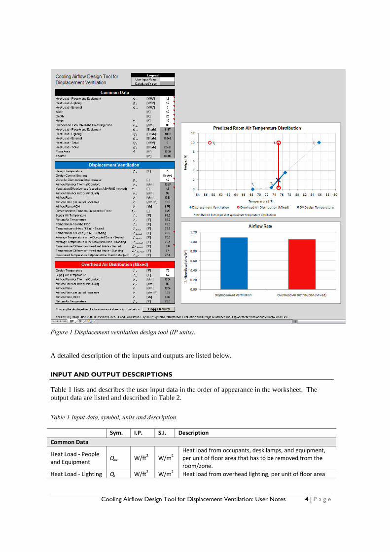
The design tool is composed of three worksheets named “IP”, “SI” and “Data Library” as indicated in the bottom-left corner of Figure 1. The user may choose either the “IP” (Inch-Pound units) or “SI” (International System units) worksheet. The “Data Library” worksheet is hidden, under default conditions. In the “Data library” there are the constant values used in the design procedure. This worksheet should be modified only by expert users. In the following, only the “IP” worksheet will be described because the “SI” worksheet is similar to the “IP” worksheet, only the units used are different. In the worksheet the user inputs are entered only in cells with a white background and the outputs (calculated values) are displayed in cells with a dark gray background (see Figure 1). The data input and output are organized into three sections, named “Common Data”, “Displacement Ventilation”, and “Overhead Air Distribution (Mixed)”. In the “Common Data” section, the majority of the required inputs, such as heat loads and room/zone dimensions are entered. Key design inputs are entered at the top of both the “Displacement Ventilation” and “Overhead Air Distribution” sections. The “Design Temperature” refers to the setpoint temperature. In the case of the stratified conditions produced by a displacement ventilation system, the user has three choices for defining the setpoint temperature using the “Design Control Strategy” input cell. As defined in the list below, the “Design Temperature” can be set equal to the average temperature of the occupied zone for seated or standing occupants, or simply set to the temperature at a height of 43 in. (1.1 m) using the “ASHRAE” label from the drop-down menu. The “Design Temperature” is shown in the graph “Predicted Room Air Temperature Distribution”. Note that in addition to “Design Temperature,” the “Overhead Air Distribution” section also permits the user to enter a “Supply Air Temperature.” This option is not available for displacement ventilation because the ASHRAE method calculates the supply air temperature based on the user design inputs. In the “Displacement Ventilation” section there are all the detailed outputs of the ASHRAE design method plus some indexes that we think can be useful in the design process. In the “Overhead Air Distribution” section there are the inputs and outputs for sizing a traditional overhead ventilation system. This section was inserted to allow users to compare the temperature profiles and the design airflow rates for the two ventilation strategies. On the right-hand side of the page, there are two graphs presenting the most important results. The top graph compares the air temperature profiles for the overhead and displacement ventilation systems, and the second one compares the design airflow rates.
Cooling Airflow Design Tool for Displacement Ventilation: User Notes 4 | P a g e
Figure 1 Displacement ventilation design tool (IP units).
A detailed description of the inputs and outputs are listed below. INPUT AND OUTPUT DESCRIPTIONS
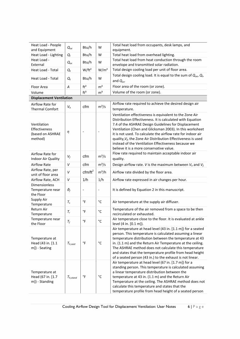
Table 1 lists and describes the user input data in the order of appearance in the worksheet. The output data are listed and described in Table 2. Table 1 Input data, symbol, units and description.
Sym. I.P. S.I. Description
Common Data
Heat Load ‐ People and Equipment
Qoe W/ft2 W/m2 Heat load from occupants, desk lamps, and equipment, per unit of floor area that has to be removed from the room/zone.
Heat Load ‐ Lighting Ql W/ft2 W/m2 Heat load from overhead lighting, per unit of floor area

Cooling Airflow Design Tool for Displacement Ventilation: User Notes 5 | P a g e
that has to be removed from the room/zone.
Heat Load ‐ External Qex W/ft2 W/m2 Heat load from heat conduction through the room envelope and transmitted solar radiation, per unit of floor area that has to be removed from the room/zone.
Width ft m Room (or zone) width.Depth ft m Room (or zone) depth. Height h ft m Room (or zone) height.
Outdoor Airflow Rate in the Breathing Zone
Vbz cfm m³/s
Design outdoor airflow required in the breathing zone of the occupied space or spaces in a zone. Vbz should be determined in accordance with Equation 6‐1 of ASHRAE 62.1‐2004.
Displacement Ventilation
Design Temperature
Td °F °C
Room (or zone) design air temperature. In an overhead system this is the thermostat temperature setpoint. For displacement ventilation there are three possible definitions, as described in the “Design Control Strategy” input (below). The “Design Temperature” is displayed in the graph “Predicted Room Air Temperature Distribution”.
Design Control Strategy
Using the drop‐down menu, the user may choose among the following three definitions for “Design Temperature”: “Seated”, “Standing”, and “ASHRAE”.
1) “Seated” –The average temperature in the occupied zone between head height (43 in. [1.1 m]) and ankle height (4 in. [0.1 m]) for a seated person, Toz,seat, is set equal to Td;
2) “Standing” – The average temperature in the occupied zone between head height (67 in. [1.7 m]) and ankle height (4 in. [0.1 m]) for a standing person, Toz,stand is set equal to Td; and
3) “ASHRAE” – The temperature at head height (43 in. [1.1 m]) – Seated, Th,seat, is set equal to Td. This last option is the assumption of the ASHRAE method.
Zone Air Distribution Effectiveness
Ez ‐ ‐
Measure of how effectively the zone air distribution uses its supply air to maintain acceptable air quality in the breathing zone. Ez is determined from Table 6‐2 of ASHRAE 62.1‐2004.
Overhead Air Distribution (Mixed)
Design Temperature
Td °F °C
Room (or zone) design air temperature. It is the thermostat (typically at 4 ft [1.2 m] height) temperature setpoint, and is also equal to the return temperature in a mixing overhead air distribution system.
Supply Air Temperature
Ts °F °C Air temperature at the overhead diffuser. It is equal to the air temperature leaving the cooling coil at the air handling unit when the duct heat gains are equal to zero.
Table 2 Output data, symbol, units and description.
Sym. I.P. S.I. Description
Common Data
Cooling Airflow Design Tool for Displacement Ventilation: User Notes 6 | P a g e
Heat Load ‐ People and Equipment
Qoe Btu/h W Total heat load from occupants, desk lamps, and equipment.
Heat Load ‐ Lighting Ql Btu/h W Total heat load from overhead lighting. Heat Load ‐ External
Qex Btu/h W Total heat load from heat conduction through the room envelope and transmitted solar radiation.
Heat Load ‐ Total Qt W/ft² W/m² Total design cooling load per unit of floor area.
Heat Load ‐ Total Qt Btu/h W Total design cooling load. It is equal to the sum of Qoe, Ql, and Qex.
Floor Area A ft² m² Floor area of the room (or zone).
Volume ft³ m³ Volume of the room (or zone).
Displacement Ventilation
Airflow Rate for Thermal Comfort
Vh cfm m³/s Airflow rate required to achieve the desired design air temperature.
Ventilation Effectiveness (based on ASHRAE method)
η - ‐
Ventilation effectiveness is equivalent to the Zone Air Distribution Effectiveness. It is calculated with Equation 7.4 of the ASHRAE Design Guidelines for Displacement Ventilation (Chen and Glicksman 2003). In this worksheet it is not used. To calculate the airflow rate for indoor air quality,Vf, the Zone Air Distribution Effectiveness is used instead of the Ventilation Effectiveness because we believe it is a more conservative value.
Airflow Rate for Indoor Air Quality
Vf cfm m³/s Flow rate required to maintain acceptable indoor air quality.
Airflow Rate V cfm m³/s Design airflow rate. V is the maximum between Vh and Vf. Airflow Rate, per unit of floor area
V cfm/ft2 m³/h Airflow rate divided by the floor area.
Airflow Rate, ACH V 1/h 1/h Airflow rate expressed in air changes per hour. Dimensionless Temperature near the Floor
θf - ‐ It is defined by Equation 2 in this manuscript.
Supply Air Temperature
Ts °F °C Air temperature at the supply air diffuser.
Return Air Temperature
Tr °F °C Temperature of the air removed from a space to be then recirculated or exhausted.
Temperature near the Floor
Tf °F °C Air temperature close to the floor. It is evaluated at ankle level (4 in. [0.1 m]).
Temperature at Head (43 in. [1.1 m]) ‐ Seating
Th,seat °F °C
Air temperature at head level (43 in. [1.1 m]) for a seated person. This temperature is calculated assuming a linear temperature distribution between the temperature at 43 in. (1.1 m) and the Return Air Temperature at the ceiling. The ASHRAE method does not calculate this temperature and states that the temperature profile from head height of a seated person (43 in.) to the exhaust is not linear.
Temperature at Head (67 in. [1.7 m]) ‐ Standing
Th,stand °F °C
Air temperature at head level (67 in. [1.7 m]) for a standing person. This temperature is calculated assuming a linear temperature distribution between the temperature at 43 in. (1.1 m) and the Return Air Temperature at the ceiling. The ASHRAE method does not calculate this temperature and states that the temperature profile from head height of a seated person
Cooling Airflow Design Tool for Displacement Ventilation: User Notes 7 | P a g e
(43 in.) to the exhaust is not linear.
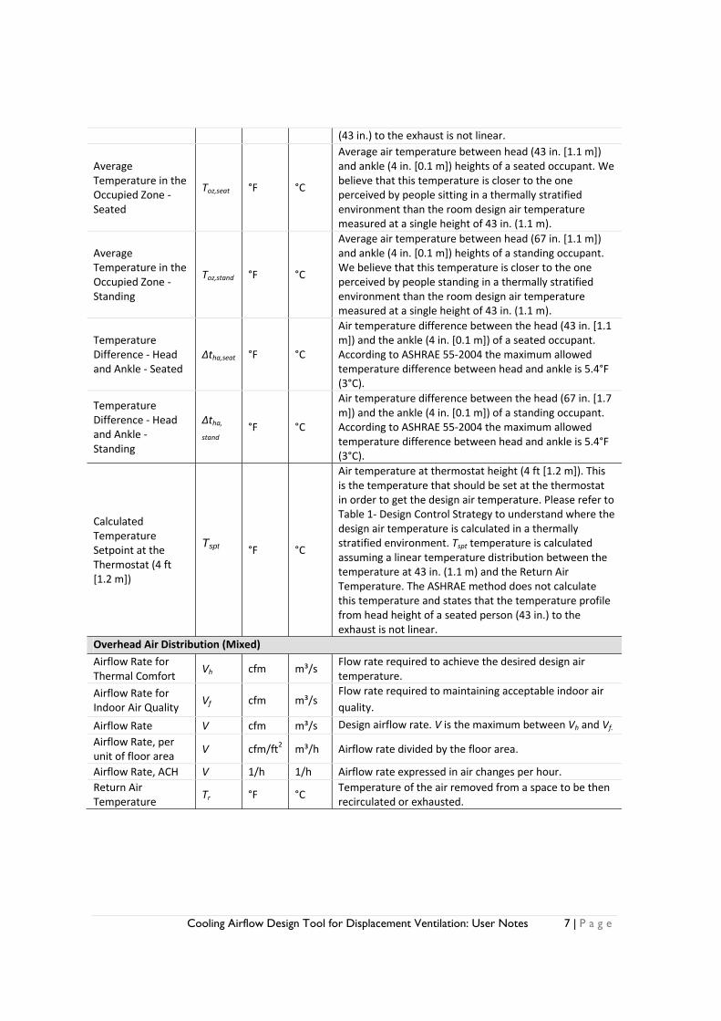
Average Temperature in the Occupied Zone ‐ Seated
Toz,seat °F °C
Average air temperature between head (43 in. [1.1 m]) and ankle (4 in. [0.1 m]) heights of a seated occupant. We believe that this temperature is closer to the one perceived by people sitting in a thermally stratified environment than the room design air temperature measured at a single height of 43 in. (1.1 m).
Average Temperature in the Occupied Zone ‐ Standing
Toz,stand °F °C
Average air temperature between head (67 in. [1.1 m]) and ankle (4 in. [0.1 m]) heights of a standing occupant. We believe that this temperature is closer to the one perceived by people standing in a thermally stratified environment than the room design air temperature measured at a single height of 43 in. (1.1 m).
Temperature Difference ‐ Head and Ankle ‐ Seated
Δtha,seat °F °C
Air temperature difference between the head (43 in. [1.1 m]) and the ankle (4 in. [0.1 m]) of a seated occupant. According to ASHRAE 55‐2004 the maximum allowed temperature difference between head and ankle is 5.4°F (3°C).
Temperature Difference ‐ Head and Ankle ‐ Standing
Δtha, stand
°F °C
Air temperature difference between the head (67 in. [1.7 m]) and the ankle (4 in. [0.1 m]) of a standing occupant. According to ASHRAE 55‐2004 the maximum allowed temperature difference between head and ankle is 5.4°F (3°C).
Calculated Temperature Setpoint at the Thermostat (4 ft [1.2 m])
Tspt
°F °C
Air temperature at thermostat height (4 ft [1.2 m]). This is the temperature that should be set at the thermostat in order to get the design air temperature. Please refer to Table 1‐ Design Control Strategy to understand where the design air temperature is calculated in a thermally stratified environment. Tspt temperature is calculated assuming a linear temperature distribution between the temperature at 43 in. (1.1 m) and the Return Air Temperature. The ASHRAE method does not calculate this temperature and states that the temperature profile from head height of a seated person (43 in.) to the exhaust is not linear.
Overhead Air Distribution (Mixed)
Airflow Rate for Thermal Comfort
Vh cfm m³/s Flow rate required to achieve the desired design air temperature.
Airflow Rate for Indoor Air Quality
Vf cfm m³/s Flow rate required to maintaining acceptable indoor air quality.
Airflow Rate V cfm m³/s Design airflow rate. V is the maximum between Vh and Vf.
Airflow Rate, per unit of floor area
V cfm/ft2 m³/h Airflow rate divided by the floor area.
Airflow Rate, ACH V 1/h 1/h Airflow rate expressed in air changes per hour. Return Air Temperature
Tr °F °C Temperature of the air removed from a space to be then recirculated or exhausted.

Cooling Airflow Design Tool for Displacement Ventilation: User Notes 8 | P a g e
In the worksheet there is also the possibility to copy in an independent sheet the results of a simulation. To activate click the button “COPY” on the line “To copy the displayed results to a new worksheet, click the button.” (See Figure 4). EXAMPLE
To demonstrate how to use the DV design tool, an example for an office building where people are primarily seated is presented. IP units are used. The design characteristics are:
• Heat loads: Qoe=1.8 W/ft²; Ql=1.2 W/ft²; Qex=3 W/ft² • Room geometry: 40 ft x 25 ft; Room height: 10 ft • According the ASHRAE 62.1-2004 the outdoor air flow rate in the Breathing Zone is
110 cfm. • Zone air distribution effectiveness for displacement ventilation is 1.2 (see ASHRAE
62.1-2004 Table 6-2). • Design temperature, Td, for displacement and overhead is equal to 75°F. • The Design Control Strategy for the displacement ventilation is “Seated”. This was
chosen because the majority of the occupants stay seated while working. • Supply Air Temperature, Ts, for the Overhead Air Distribution (Mixed) is set to 57°F.
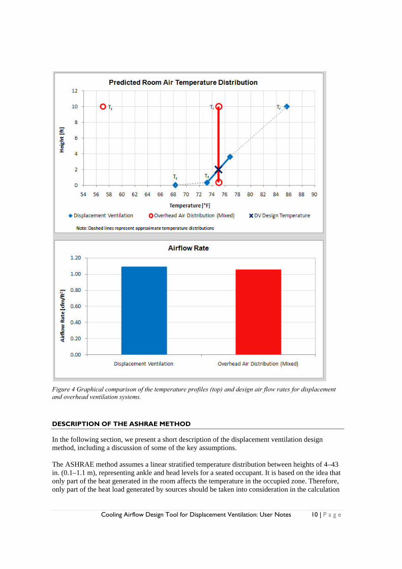
The inputs are shown in Figure 2 and the outputs are shown in Figure 3. The temperature profiles and airflow rates are compared in Figure 4.
Figure 2 Screenshot of the input data in the “Common Data”, “Displacement Ventilation” and “Overhead Air Distribution (Mixed)” sections.

Cooling Airflow Design Tool for Displacement Ventilation: User Notes 9 | P a g e
Figure 3 Screenshot of the output data in the “Displacement Ventilation” and “Overhead Air Distribution (Mixed)” sections.
Note that in this example, the temperature at head height for a seated person, Th,seat= 76.8°F, is much higher than the design temperature, Td= 75°F. Also, to control this space with a thermostat at 4 ft (1.2 m) height, the setpoint should be increased to 77.4°F. Setting the thermostat to 75°F would result in an Average Temperature in the Occupied Zone – Seated, Toz,seat equal to 72.6°F.
Cooling Airflow Design Tool for Displacement Ventilation: User Notes 10 | P a g e
Figure 4 Graphical comparison of the temperature profiles (top) and design air flow rates for displacement and overhead ventilation systems.
DESCRIPTION OF THE ASHRAE METHOD
In the following section, we present a short description of the displacement ventilation design method, including a discussion of some of the key assumptions. The ASHRAE method assumes a linear stratified temperature distribution between heights of 4–43 in. (0.1–1.1 m), representing ankle and head levels for a seated occupant. It is based on the idea that only part of the heat generated in the room affects the temperature in the occupied zone. Therefore, only part of the heat load generated by sources should be taken into consideration in the calculation

Cooling Airflow Design Tool for Displacement Ventilation: User Notes 11 | P a g e
of the airflow rate, Vh. A dimensionless temperature is used to predict the temperature stratification in the zone. The dimensionless temperature at a height in the room is generally defined by the following equation:
(1)
where T, Ts, and Tr, are, respectively, the point, supply and return air temperatures. For modeling purposes, it is assumed that the temperatures at all points at the same room height are equal. The ASHRAE method uses the dimensionless temperature at the floor, θf , as defined in equation (2).
(2)
where Tf is the air temperature measured close to the floor, usually at ankle height (4 in. [0.1 m]), and away from the local influence of any supply diffuser. Tf is representative of the bottom point of the vertical temperature profile. In order to estimate the vertical temperature profile in the occupied zone, the method first establishes the value for the temperature near the floor, θf. θf is defined by equation (2) and calculated in the design process by equation (3) developed by Mundt (1996):
1
60 1 1 1 (3)
Where:
A= Floor area [ft2] V= Airflow rate [cfm] cp= Specific heat of air. Assumed to be 0.24 Btu/(lb°F) at standard conditions αc= Convective heat transfer coefficient. Assumed to be equal to 1 Btu/(h ft2°F) αr= Radiant heat transfer coefficient. Assumed to be equal to 1 Btu/(h ft2°F) ρ= Air density. Assumed to be equal to 0.075 lb/ft3 (Air temperature = 70°F) Equation (2) can be simplified into equation (3) using the above assumptions.
2.16
(4)
The design procedure is as follows:
1) Select a room design air temperature at 43 in. (1.1 m) above the floor (Th). Chen and Glicksman decided to set the temperature at head height for a seated person equal to the design temperature. This implies that the air temperature measured by the thermostat (4 ft) will be slightly higher. Therefore the setpoint at the thermostat should be fixed to a higher value. In the spreadsheet we added the Average temperature in the Occupied Zone for a Seated, Toz,seat, and Standing, Toz,stand, occupant. We believe that this temperature is closer to the one perceived by a seated (or standing) person in a thermally stratified environment than a single room design air temperature measured at 43 in. (1.1 m), Therefore we recommend the use of the average occupied zone temperature (seated or standing) as the design (control) temperature in the room using the “Design Control Strategy” cell (see below).
2) Calculate summer design cooling load, Qt. Itemize the cooling load in three parts, Qt= Qoe+ Ql+ Qex where: • Qoe [Btu/h] is the heat gain from occupants, desk lamps, and equipment. • Ql [Btu/h] is the heat gain from overhead lighting. • Qex [Btu/h] is the heat gain from heat conduction through the room envelope and
transmitted solar radiation. This heat load is primarily associated with warm exterior wall and window temperatures. Direct sunshine on the floor increases the floor surface
Cooling Airflow Design Tool for Displacement Ventilation: User Notes 12 | P a g e
temperature, thus generating increased mixing in the room and possibly disrupting the temperature stratification. The ASHRAE method is based on a validated CFD model. CFD tools cannot properly simulate direct solar radiation, hence, the ASHRAE method is not able to properly take into account the problems related to direct solar radiation.
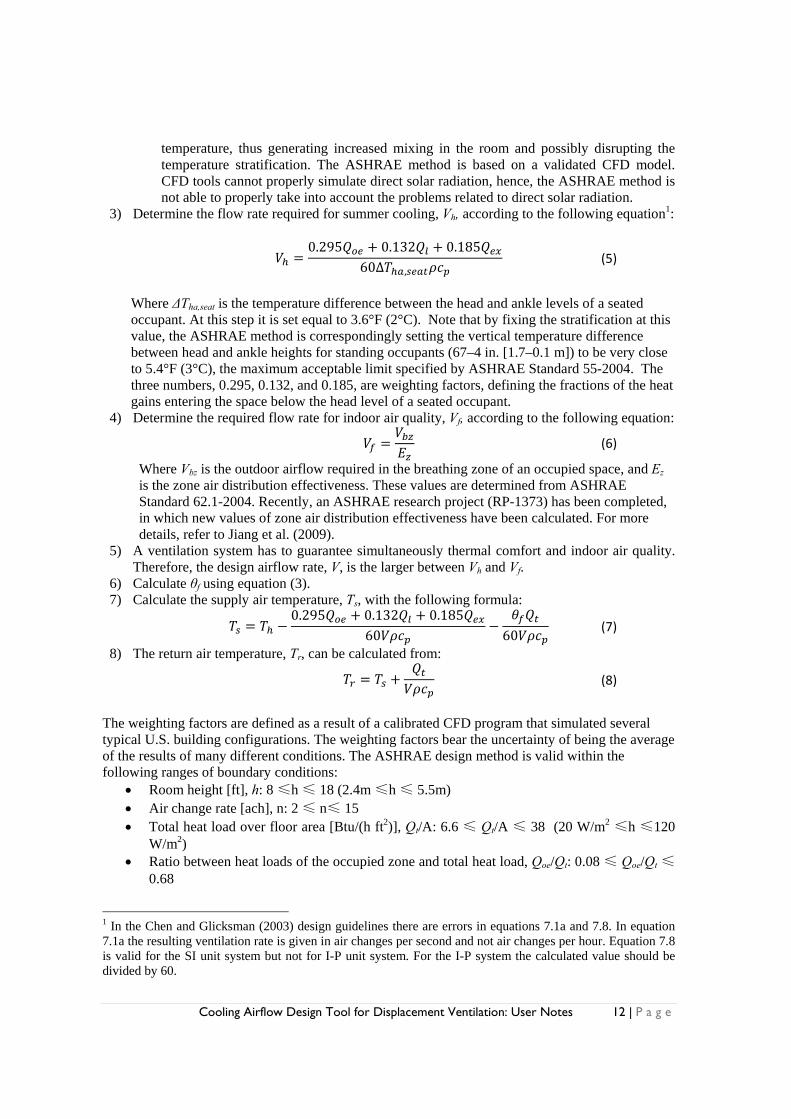
3) Determine the flow rate required for summer cooling, Vh, according to the following equation1:
0.295 0.132 0.185
60∆ , (5)
Where ΔTha,seat is the temperature difference between the head and ankle levels of a seated occupant. At this step it is set equal to 3.6°F (2°C). Note that by fixing the stratification at this value, the ASHRAE method is correspondingly setting the vertical temperature difference between head and ankle heights for standing occupants (67–4 in. [1.7–0.1 m]) to be very close to 5.4°F (3°C), the maximum acceptable limit specified by ASHRAE Standard 55-2004. The three numbers, 0.295, 0.132, and 0.185, are weighting factors, defining the fractions of the heat gains entering the space below the head level of a seated occupant.
4) Determine the required flow rate for indoor air quality, Vf, according to the following equation:
(6)
Where Vbz is the outdoor airflow required in the breathing zone of an occupied space, and Ez is the zone air distribution effectiveness. These values are determined from ASHRAE Standard 62.1-2004. Recently, an ASHRAE research project (RP-1373) has been completed, in which new values of zone air distribution effectiveness have been calculated. For more details, refer to Jiang et al. (2009).
5) A ventilation system has to guarantee simultaneously thermal comfort and indoor air quality. Therefore, the design airflow rate, V, is the larger between Vh and Vf.
6) Calculate θf using equation (3). 7) Calculate the supply air temperature, Ts, with the following formula:
0.295 0.132 0.185
60 60 (7)
8) The return air temperature, Tr, can be calculated from:
(8)
The weighting factors are defined as a result of a calibrated CFD program that simulated several typical U.S. building configurations. The weighting factors bear the uncertainty of being the average of the results of many different conditions. The ASHRAE design method is valid within the following ranges of boundary conditions:
• Room height [ft], h: 8 ≤h ≤ 18 (2.4m ≤h ≤ 5.5m) • Air change rate [ach], n: 2 ≤ n≤ 15 • Total heat load over floor area [Btu/(h ft2)], Qt/A: 6.6 ≤ Qt/A ≤ 38 (20 W/m2 ≤h ≤120
W/m2) • Ratio between heat loads of the occupied zone and total heat load, Qoe/Qt: 0.08 ≤ Qoe/Qt ≤
0.68
1 In the Chen and Glicksman (2003) design guidelines there are errors in equations 7.1a and 7.8. In equation 7.1a the resulting ventilation rate is given in air changes per second and not air changes per hour. Equation 7.8 is valid for the SI unit system but not for I-P unit system. For the I-P system the calculated value should be divided by 60.

Cooling Airflow Design Tool for Displacement Ventilation: User Notes 13 | P a g e
• Ratio between overhead lighting and total heat load, Ql/Qt: 0 ≤ Ql/Qt ≤ 0.43 • Ratio between heat load coming from heat conduction through the room envelope plus
transmitted solar radiation and total heat load, Qex/Qt: 0 ≤ Qex/Qt ≤ 0.92 •
DESIGN CONTROL STRATEGY
In a thermally stratified environment, an occupant is exposed to several air temperatures, lower in the lower parts of the body and higher in its upper parts. There is not one height where a single temperature measurement can be made to describe the entire stratified environment. The ASHRAE method fixes the Temperature at Head (43 in. [1.1 m]) – Seated, Th,seat, equal to the design temperature. This implies that a seated occupant will be exposed to a lower temperature than the one desired by the designer. The risk of cool thermal discomfort may increase. In the design spreadsheet there is the possibility to apply a different design control strategy from that assumed by the ASHRAE method. This is done by setting the average temperature in the occupied zone for a seated or a standing person equal to the design temperature. To enable the calculation of the average temperature for a standing person and the thermostat setpoint temperature (4 ft [1.2 m] height), we estimated the vertical temperature profile between the 43-in. height and the ceiling. The ASHRAE method does not calculate this profile and states that it is not linear. We used a linear approximation for the profile and believe that it is reasonable and helps to reduce the above mentioned thermal discomfort risk. In the “Displacement Ventilation” section, the user may choose among the following three design control strategies: “Seated”, “Standing”, and “ASHRAE”. FINAL REMARKS
Displacement ventilation should not be used for heating because the buoyancy and low supply air velocity will drive the hot supply air to the ceiling level where the air will be extracted generating a short circuit. If heating is necessary in winter, an independent heating system (radiant panels, convectors, radiators or fan coil units at floor level, etc.) is necessary. According to Chen and Glicksman (1999) displacement ventilation may preserve a comfortable environment if the cooling load does not exceed 11.2 W/ft2 (40 Btu/(h ft2)). The ASHRAE design method does not take into account the possibility of using radiant systems for removing part of the cooling load, therefore the method should not be applied with this system. A cooled ceiling will decrease the room temperature stratification and a cooled floor may increase the risk of cool discomfort at the ankle level. Field measurements in offices with displacement ventilation have demonstrated that drafts at ankle level are the most frequent occupant complaint (Melikov et al. 2005). Therefore, the prediction of temperature profile in the room and the choice of air diffuser type, size and location should be carefully performed. Nielsen et al. (1998) showed that in order to reduce the temperature gradient in the occupied zone, it is necessary to increase the entrainment of room air. This can be done by using higher efficiency air diffusers. The ASHRAE method does not take into account the influence of diffuser type.

Cooling Airflow Design Tool for Displacement Ventilation: User Notes 14 | P a g e
REFERENCE
• Chen, Q. and Glicksman, L. (2003) “System Performance Evaluation and Design Guidelines for Displacement Ventilation” Atlanta: ASHRAE.
• Jiang, Z., Chen, Q., and Lee, K. (2009) “Air Distribution Effectiveness with Stratified Air Distribution Systems.” Final Report, ASHRAE Research Project – 1373. Available from ASHRAE.
• Melikov, A.K., Pitchurov, G., Naydenov, K. and Langkilde, G. (2005) “Field study of occupants’ thermal comfort in rooms with displacement ventilation” Indoor Air 15 (3): 205-214.
• Mundt, E. (1996) “The performance of displacement ventilation system” Ph.D. thesis, Royal Institute of Technology, Sweden.
• Nielsen, P.V., Hoff, L., Pedersen, L.G. (1998) “Displacement ventilation by different type of diffusers”. Proc. of the 9th AIVC conference. ISBN 0946075 409, Warwick, Poland.
• Skistad, H., Mundt, E., Nielsen, P.V., Hagstrom, K., Railo, J. (2002) “Displacement ventilation in non-industrial premises” Guidebook n. 1, REHVA - Federation of European Heating and Air-Conditioning Associations.
ACKNOWLEDGEMENTS
This work was supported by the Center for the Built Environment (CBE) at the University of California, Berkeley. The Center's work is supported by CBE's Industry Partners, a consortium of corporations and organizations committed to improving the design and operation of commercial buildings. Current CBE Partners include: Armstrong World Industries, Arup, California Energy Commission, Charles M. Salter, Associates, Coherent Structures, Cohos Evamy, DPR Construction, EHDD Architecture, Engineered Interiors Group, Environmental Systems Design, Glumac, Haworth, HOK, KlingStubbins, Larson Binkley, Pacific Gas and Electric Company, Price Industries, Rumsey Engineers, CPP, Mahlum Architects, Mithun, Perkins + Will, Skidmore Owings and Merrill, Southern California Edison, Steelcase, Syska Hennessy Group, Tate Access Floors, Taylor Engineering, CTG Energetics, Guttmann & Blaevoet, Southland Industries, Swinerton Builders, Uponor, U.S. Department of Energy (DOE), U.S. General Services Administration (GSA), Webcor Builders, WSP Flack + Kurtz, and Zimmer Gunsul Frasca Architects.