c l i c compact linear collider (clic) studyaccelconf.web.cern.ch/accelconf/r08/talks/moaau03.pdfc l...
TRANSCRIPT

C L I CC L I C
J.P.Delahaye CLIC to RUPAC08 (29 – 09 – 08) 1
J.P.Delahaye
for
The Compact LInear Collider Study Team&
The CLIC/CTF3 Collaboration
STATUS and TRENDS of the COMPACT LINEAR COLLIDER
(CLIC) STUDY
http://clic-study.web.cern.ch/CLIC-Study/
C L I CC L I C
J.P.Delahaye CLIC to RUPAC08 (29 – 09 – 08) 2
OUTLINE
• Linear Colliders in the HEP world-wide landscape• The Compact Linear Collider (CLIC) concept
• Design and new parameters recently adopted• Main challenges and key issues• The facilities to address the feasibility issues• Plans and schedule
• Fruitful contribution of Russian Institutes• Conclusion
C L I CC L I C
J.P.Delahaye CLIC to RUPAC08 (29 – 09 – 08) 3 3
High Energy Physics after LHC a world-wide consensus
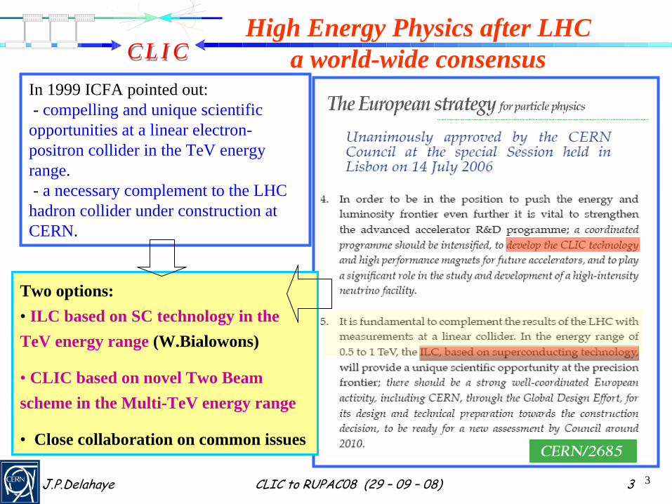
In 1999 ICFA pointed out:- compelling and unique scientific opportunities at a linear electron- positron collider in the TeV energy range.- a necessary complement to the LHC hadron collider under construction at CERN.
Two options:• ILC based on SC technology in the TeV energy range (W.Bialowons)
• CLIC based on novel Two Beam scheme in the Multi-TeV energy range
• Close collaboration on common issues

C L I CC L I C
J.P.Delahaye CLIC to RUPAC08 (29 – 09 – 08) 4
Site independent feasibility study aiming at the development of a realistic technology to extend e-/e+ linear colliders into the Multi- TeV energy range:
ECM energy range complementary to LHC =>ECM = 0.5- 3 TeV
L > few 1034 cm-2 with acceptable background ⇒ ECM and L to be reviewed when LHC physics results avail.Affordable cost and power consumption
Physics motivation: http://clicphysics.web.cern.ch/CLICphysics/"Physics at the CLIC Multi-TeV Linear Collider:by the CLIC Physics Working Group:CERN 2004-5
Present goal:Design of a Linear Collider based on CLIC technology and address all key
feasibility issues described in a Conceptual Design Report including Cost estimation by 2010
THE COMPACT LINEAR COLLIDER (CLIC) STUDYhttp://clic-study.web.cern.ch/CLIC-Study/

C L I CC L I C
J.P.Delahaye CLIC to RUPAC08 (29 – 09 – 08) 5
CLIC – basic features
•
“Compact”
collider –
total length < 50 km at 3 TeV•
Normal conducting acceleration structures at high frequency
• Novel Two-Beam Acceleration Scheme•
Cost effective, reliable, efficient
•
Simple tunnel, no active elements•
Modular, easy energy upgrade in stages
CLIC TUNNEL CROSS-SECTION
4.5 m diameter
QUAD
QUAD
POWER EXTRACTIONSTRUCTURE
BPM
ACCELERATINGSTRUCTURES
Drive beam - 95 A, 240 nsfrom 2.4 GeV to 240 MeVMain beam – 1 A, 156 ns
from 9 GeV to 1.5 TeV100 MV/m
12 GHz – 64 MW
• High acceleration gradient: > 100 MV/m

C L I CC L I C
J.P.Delahaye CLIC to RUPAC08 (29 – 09 – 08) 6
e+ injector, 2.4 GeV
e- injector2.4 GeV
CLIC overall layout3 TeV
e+ main linace- main linac , 12 GHz, 100 MV/m, 21 km
BC2BC2
BC1
e+ DR365m
e- DR365m
booster linac, 9 GeV, 2 GHz
decelerator, 24 sectors of 868 m
IP1
BDS2.75 km
BDS2.75 km
48 km
drive beam accelerator2.37 GeV, 1.0 GHz
combiner rings Circumferences delay loop 80.3 m
CR1 160.6 mCR2 481.8 m
CR1CR2
delayloop
326 klystrons33 MW, 139 μs
1 km
CR2delayloop
drive beam accelerator2.37 GeV, 1.0 GHz
326 klystrons33 MW, 139 μs
1 km
CR1
TAR=120m
TAR=120m
245m 245m
Drive Beam Generation Complex
Main Beam Generation Complex
Main & Drive Beam generationcomplexes not to scale
C L I CC L I C
J.P.Delahaye CLIC to RUPAC08 (29 – 09 – 08) 7
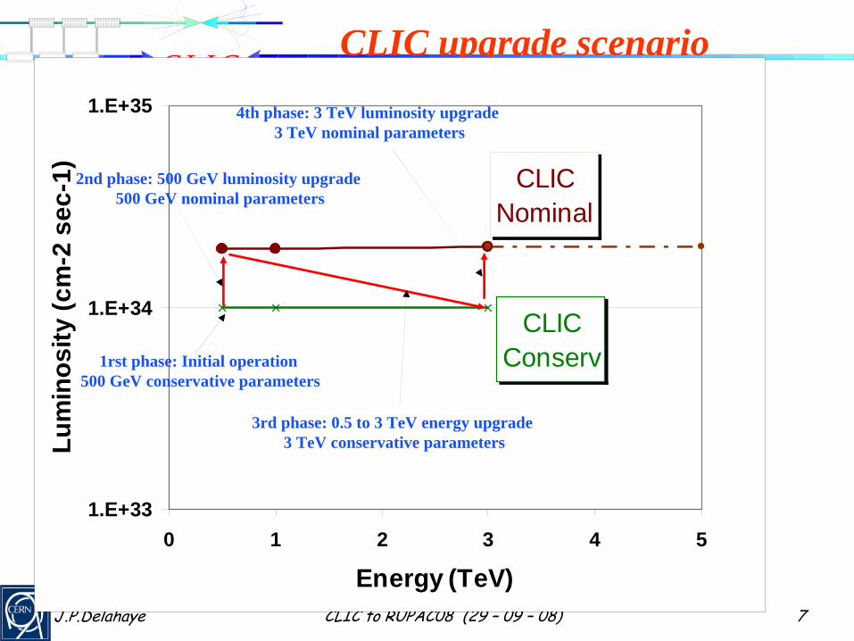
CLIC upgrade scenario
CLICNominal
CLICConserv
1.E+33
1.E+34
1.E+35
0 1 2 3 4 5
Energy (TeV)
Lum
inos
ity (c
m-2
sec
-1)
1rst phase: Initial operation 500 GeV conservative parameters
2nd phase: 500 GeV luminosity upgrade 500 GeV nominal parameters
3rd phase: 0.5 to 3 TeV energy upgrade 3 TeV conservative parameters
4th phase: 3 TeV luminosity upgrade 3 TeV nominal parameters
C L I CC L I C
J.P.Delahaye CLIC to RUPAC08 (29 – 09 – 08) 8
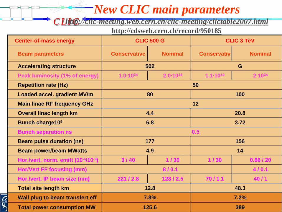
New CLIC main parameters http://clic-meeting.web.cern.ch/clic-meeting/clictable2007.html
Center-of-mass energy CLIC 500 G CLIC 3 TeV
Beam parameters Conservative Nominal Conservativ Nominal
Accelerating structure 502 GPeak luminosity (1% of energy) 1.0·1034 2.0·1034 1.1·1034 2·1034
Repetition rate (Hz) 50Loaded accel. gradient MV/m 80 100Main linac RF frequency GHz 12Overall linac length km 4.4 20.8Bunch charge109 6.8 3.72Bunch separation ns 0.5Beam pulse duration (ns) 177 156Beam power/beam MWatts 4.9 14Hor./vert. norm. emitt (10-6/10-9) 3 / 40 1 / 30 1 / 30 0.66 / 20Hor/Vert FF focusing (mm) 8 / 0.1 4 / 0.1Hor./vert. IP beam size (nm) 221 / 2.8 128 / 2.5 70 / 1.1 40 / 1Total site length km 12.8 48.3Wall plug to beam transfert eff 7.8% 7.2%
Total power consumption MW 125.6 389
http://cdsweb.cern.ch/record/950185
C L I CC L I C
J.P.Delahaye CLIC to RUPAC08 (29 – 09 – 08) 9
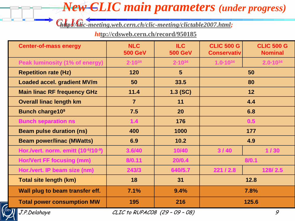
New CLIC main parameters (under progress) http://clic-meeting.web.cern.ch/clic-meeting/clictable2007.html;
http://cdsweb.cern.ch/record/950185
Center-of-mass energy NLC500 GeV
ILC500 GeV
CLIC 500 GConservativ
CLIC 500 GNominal
Peak luminosity (1% of energy) 2·1034 2·1034 1.0·1034 2.0·1034
Repetition rate (Hz) 120 5 50Loaded accel. gradient MV/m 50 33.5 80Main linac RF frequency GHz 11.4 1.3 (SC) 12Overall linac length km 7 11 4.4Bunch charge109 7.5 20 6.8Bunch separation ns 1.4 176 0.5Beam pulse duration (ns) 400 1000 177Beam power/linac (MWatts) 6.9 10.2 4.9Hor./vert. norm. emitt (10-6/10-9) 3.6/40 10/40 3 / 40 1 / 30Hor/Vert FF focusing (mm) 8/0.11 20/0.4 8/0.1Hor./vert. IP beam size (nm) 243/3 640/5.7 221 / 2.8 128/ 2.5Total site length (km) 18 31 12.8
Wall plug to beam transfer eff. 7.1% 9.4% 7.8%
Total power consumption MW 195 216 125.6

C L I CC L I C
J.P.Delahaye CLIC to RUPAC08 (29 – 09 – 08) 10
2/1
2/1
**
2
4 ∗
××∝=
nycm
ACACbeamB
yxcm
repbb
U
PU
fNkL
ε
ηδσσπ
energy loss by beamstrahlung
center-of-mass energy Vertical
emittance
wall-plug power
wall-plug to beamefficiency
Linear Collider major parameters and challenges
•
High Beam Power (several MWatts)•
Wall-plug to beam transfer efficiency
as high as possible (several %)•
Generation & preservation of beam
emittances
at I.P. as small as possible (few nmrad)•
Beam focusing to very small dimentions
at IP (few nm)•
Beamstrahlung
energy spread
increasing with c.m. colliding energies
• Luminosity:
C L I CC L I C
J.P.Delahaye CLIC to RUPAC08 (29 – 09 – 08) 11 11EPAC 2008 CLIC / CTF3 G.Geschonke, CERN
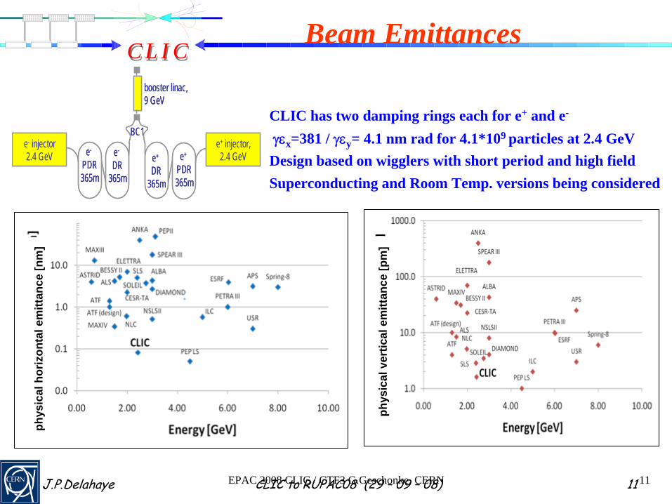
Beam Emittances
e+ injector, 2.4 GeV
e- injector2.4 GeV
BC1
e+
DR365m
e-
DR365m
booster linac, 9 GeV
e+
PDR365m
e-
PDR365m
e+ injector, 2.4 GeV
e- injector2.4 GeV
BC1
e+
DR365m
e-
DR365m
booster linac, 9 GeV
e+
PDR365m
e-
PDR365m
CLIC has two damping rings each for e+ and e-
γεx =381 / γεy = 4.1 nm rad for 4.1*109 particles at 2.4 GeVDesign based on wigglers with short period and high fieldSuperconducting and Room Temp. versions being considered
phys
ical
ver
tical
em
ittan
ce[p
m]
phys
ical
hor
izon
tal e
mitt
ance
[nm
]

C L I CC L I C
J.P.Delahaye CLIC to RUPAC08 (29 – 09 – 08) 12
Beam emittances at Damping Rings
30
ATFachieved
ILC
ATFDesign
SLC
CLIC DRdesign
CLIC 500 GeVCLIC
3 TeV SLS
NSLS IIscaled
0.001
0.010
0.100
1.000
10.0000.1 1 10 100
Horizontal Emittance (μrad-m)
Vert
ical
Em
ittan
ce (μ
rad-
m)
C L I CC L I C
J.P.Delahaye CLIC to RUPAC08 (29 – 09 – 08) 13
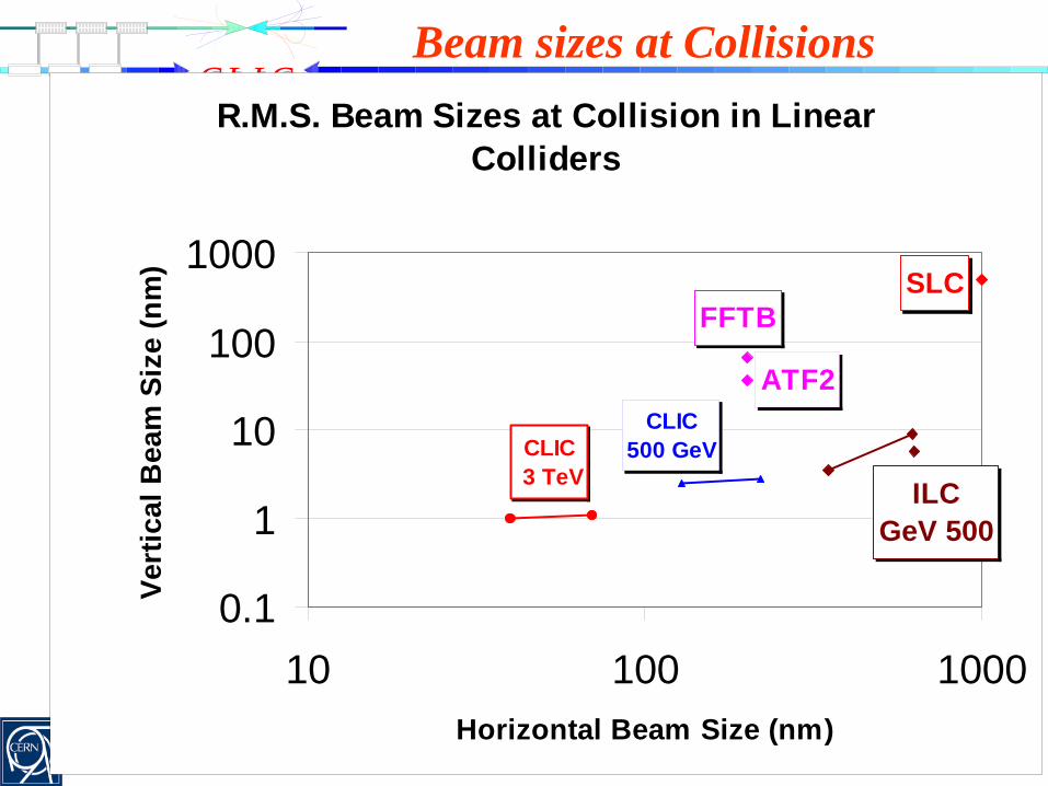
Beam sizes at CollisionsR.M.S. Beam Sizes at Collision in Linear
Colliders
ATF2
SLCFFTB
ILCGeV 500
CLIC500 GeVCLIC
3 TeV
0.1
1
10
100
1000
10 100 1000Horizontal Beam Size (nm)
Vert
ical
Bea
m S
ize
(nm
)

C L I CC L I C
J.P.Delahaye CLIC to RUPAC08 (29 – 09 – 08) 14
Tentative long-term CLIC scenario Shortest, Success Oriented, Technically Limited Schedule
Technology evaluation and Physics assessment based on LHC resultsfor a possible decision on Linear Collider funding with staged
construction starting with the lowest energy required by Physics
FirstBeam
TDRCDR Projectapproval ?
2007 2008 2009 2010 2011 2012 2013 2014 2015 2016 2017 2018 2019 2020 2021 2022 2023
Feasibility issues (Accelerator&Detector) Conceptual design and cost estimation
Design finalisation and technical design
Engineering optimisation
Project approval & final cost
Construction accelerator (poss. staged)Construction detector
C L I CC L I C
J.P.Delahaye CLIC to RUPAC08 (29 – 09 – 08) 15
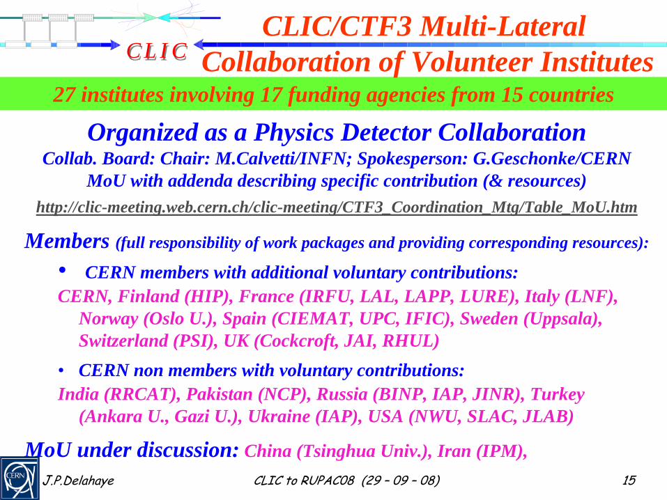
27 institutes involving 17 funding agencies from 15 countries
Organized as a Physics Detector CollaborationCollab. Board: Chair: M.Calvetti/INFN; Spokesperson: G.Geschonke/CERN
MoU with addenda describing specific contribution (& resources)http://clic-meeting.web.cern.ch/clic-meeting/CTF3_Coordination_Mtg/Table_MoU.htm
Members (full responsibility of work packages and providing corresponding resources):
• CERN members with additional voluntary contributions:CERN, Finland (HIP), France (IRFU, LAL, LAPP, LURE), Italy (LNF),
Norway (Oslo U.), Spain (CIEMAT, UPC, IFIC), Sweden (Uppsala), Switzerland (PSI), UK (Cockcroft, JAI, RHUL)
• CERN non members with voluntary contributions:India (RRCAT), Pakistan (NCP), Russia (BINP, IAP, JINR), Turkey
(Ankara U., Gazi U.), Ukraine (IAP), USA (NWU, SLAC, JLAB)
MoU under discussion: China (Tsinghua Univ.), Iran (IPM),
CLIC/CTF3 Multi-Lateral Collaboration of Volunteer Institutes

C L I CC L I C
J.P.Delahaye CLIC to RUPAC08 (29 – 09 – 08) 1616EPAC 2008 CLIC / CTF3 G.Geschonke, CERN
IRFU/Saclay (France)Helsinki Institute of Physics (Finland) IAP (Russia)IAP NASU (Ukraine)Instituto de Fisica Corpuscular
(Spain)INFN / LNF (Italy)J.Adams Institute, (UK)
Oslo UniversityPSI (Switzerland),Polytech. University of Catalonia (Spain)RAL (England)RRCAT-Indore (India)Royal Holloway, Univ. London, (UK) SLAC (USA)Svedberg Laboratory (Sweden)Uppsala University (Sweden)
Ankara University (Turkey)Berlin Tech. Univ. (Germany) BINP (Russia)CERNCIEMAT (Spain)Finnish Industry (Finland)Gazi Universities (Turkey)
JASRI (Japan) JINR (Russia)JLAB (USA) KEK (Japan) LAL/Orsay (France) LAPP/ESIA (France)LLBL/LBL (USA)NCP (Pakistan)North-West. Univ. Illinois (USA)
27 collaborating institutes
http://clic-meeting.web.cern.ch/clic-meeting/CTF3_Coordination_Mtg/Table_MoU.htm24 members representing 27 institutes involving 17 funding agencies of 15 countries
World-wide CLIC / CTF3 collaboration

C L I CC L I C
J.P.Delahaye CLIC to RUPAC08 (29 – 09 – 08) 17
CLIC organizational Chart http://clic-study.web.cern.ch/CLIC-Study/Mtgs_Wkg_Grp.htm
CLIC/CTF3 Collab. BoardM.Calvetti/LNF
CLIC Steering CommitteeJ.P.Delahaye
CLIC Advisory CommitteeT.Raubenheimer/SLAC
CLIC Design J.P.Delahaye
CLIC Physics & DetectorsL.Linssen & D.Schlatter
CTF3 projectG.Geschonke
Conceptual Design ReportEditorial Board H.Schmickler
C L I CC L I C
J.P.Delahaye CLIC to RUPAC08 (29 – 09 – 08) 18
CLIC Work program till 2010
•
Demonstrate feasibility of CLIC technology•
Major key issues addressed in CTF3
•
Design of a linear Collider based on CLIC technologyhttp://clic-study.web.cern.ch/CLIC-Study/Design.htm
•
Estimation of its cost in the CERN area
•
CLIC Physics study and detector development:http://clic-meeting.web.cern.ch/clic-meeting/CLIC_Phy_Study_Website/default.html
•
Conceptual Design Report including cost by 2010

C L I CC L I C
J.P.Delahaye CLIC to RUPAC08 (29 – 09 – 08) 19
Strategy to address key issues•
Key issues common to all Linear Collider studies
independently of the chosen technology in close collaboration with the International Linear Collider (ILC) study:
•
On Accelerator Test Facility (ATF1&ATF2@KEK)•
With European Laboratories in the frame of the Coordinated
Accelerator Research in Europe (CARE)
and of a “Design Study”
(EUROTeV)
funded by EU Framework Programmes (FP6
presently and FP7 “EUCARD”
Integrated Activity from 2009)
•
Key issues specific to CLIC technology:•
Focus of the CLIC study
•
All R1 (feasibility) and R2 (design finalisation) key issues addressed in test facilities: CTF1,2,3@CERN
C L I CC L I C
J.P.Delahaye CLIC to RUPAC08 (29 – 09 – 08) 20
Fruitful CLIC /ILC Collaboration
•
Constructive exchange of view with B.Barish
during his visit at CERN in Nov 07http://www.linearcollider.org/cms/?pid=1000465
•
Collaboration meeting with ILC Project managers and specific experts on 08/02/08 at CERN for
collaboration
on subjects with strong synergy between CLIC and ILC:1) Civil Engineering and Conventional Facilities2) Beam Delivery Systems & Machine Detector Interf.3) Detectors4) Cost & Schedule5) Beam dynamics & Beam Simulations
•
Mandate and work plan by nominated conveners:http://indico.cern.ch/conferenceDisplay.py?confId=27435

C L I CC L I C
J.P.Delahaye CLIC to RUPAC08 (29 – 09 – 08) 21
CLIC R&D Major Test Facilities (* common issue with ILC)
Test Facility Name HostLab
Organizedby
Issues Tentative Dateof demonstration
CLIC Test Facility CTF3 CERN CLIC/CTF3 collaboration
Test of damped accelerating structure at design gradient and pulse length
Validation of the drive beam generation scheme with a fully loaded linac
Design & test of PETS ON-OFFValidation of beam stability and
losses in the drive beam decelerator,
Test of a relevant linac sub-unit with beam
TBTS in CL:EX:2009
CTF3 complex:2005 to 2009
TBL in CLEX: 2010
TBTS in CLEX: 2009
TBTS in CLEX: 2009
SLAC NLCTA SLAC SLAC Accelerating Structures 2007-2010
KEK KEK KEK Accelerating structures 2008-2010
Accelerator Test Facility ATF KEK ATF
Collaboration Damping Ring* 2009-2010
Cornell Test Accelerator
CESR-TA
Cornel
l Cornell Damping Ring:*
electron cloud* 2009-2010
National Synchr.Light Source NSLSII BNL BNL Damping Ring:
Hor. Emittance: 2 micrometer 2010
Swiss Light Source SLS PSI PSDI Damping Ring:
Vert. emittance: 10 nm 2010
Beam Delivery Test Facility ATF-2 KEK ATF
CollaborationBeam Delivery: strong focusing*& 35 nm vert
beam sizes* 2010
C L I CC L I C
J.P.Delahaye CLIC to RUPAC08 (29 – 09 – 08) 22
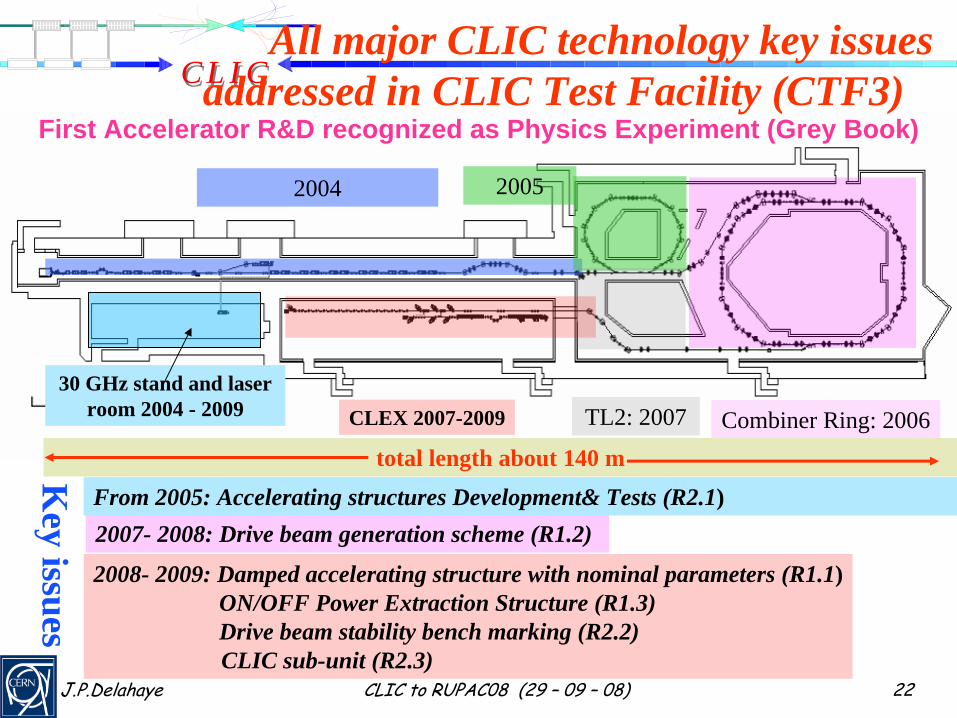
CLEX 2007-2009
2004 2005
All major CLIC technology key issues addressed in CLIC Test Facility (CTF3)
Combiner Ring: 200630 GHz stand and laser
room 2004 - 2009 TL2: 2007
2007- 2008: Drive beam generation scheme (R1.2)
2008- 2009: Damped accelerating structure with nominal parameters (R1.1)ON/OFF Power Extraction Structure (R1.3)Drive beam stability bench marking (R2.2)CLIC sub-unit (R2.3)
From 2005: Accelerating structures Development& Tests (R2.1)
Key issues
First Accelerator R&D recognized as Physics Experiment (Grey Book)
total length about 140 m
C L I CC L I C
J.P.Delahaye CLIC to RUPAC08 (29 – 09 – 08) 23
2005
2004
CLEX
CR
TL1
DL
TL2
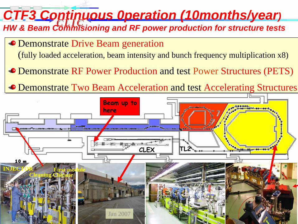
Jan 2007
Beam up to
here
Demonstrate Drive Beam generation (fully loaded acceleration, beam intensity and bunch frequency multiplication x8)
Demonstrate RF Power Production and test Power Structures (PETS)
Demonstrate Two Beam Acceleration and test Accelerating Structures
Demonstrate Drive Beam generation (fully loaded acceleration, beam intensity and bunch frequency multiplication x8)
Demonstrate RF Power Production and test Power Structures (PETS)
Demonstrate Two Beam Acceleration and test Accelerating Structures
Cleaning ChicaneFirst moduleINJECTOR
CTF3 Continuous 0peration (10months/year)HW & Beam Commisioning and RF power production for structure tests
C L I CC L I C
J.P.Delahaye CLIC to RUPAC08 (29 – 09 – 08) 24
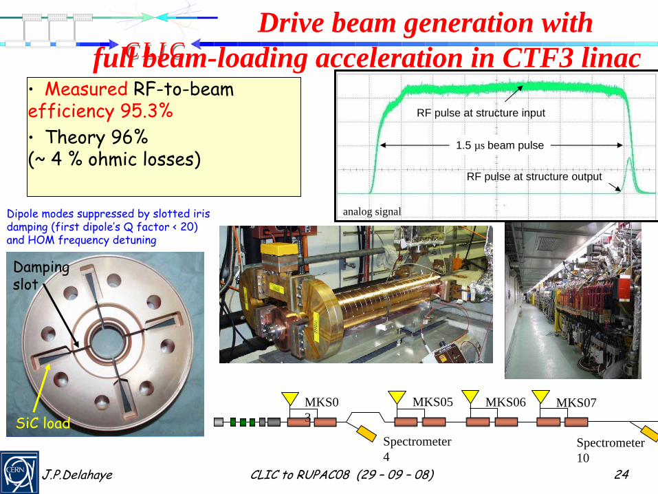
MKS0 3
MKS07MKS06MKS05
Spectrometer 10
Spectrometer 4
RF pulse at structure output
RF pulse at structure input
analog signal
1.5 µs beam pulse
Drive beam generation withfull beam-loading acceleration in CTF3 linac
•
Measured
RF-to-beam efficiency 95.3%•
Theory 96%
(~ 4 % ohmic
losses)
SiC
load
Damping slot
Dipole modes suppressed by slotted iris damping (first dipole’s Q factor < 20)and HOM frequency detuning
C L I CC L I C
J.P.Delahaye CLIC to RUPAC08 (29 – 09 – 08) 25
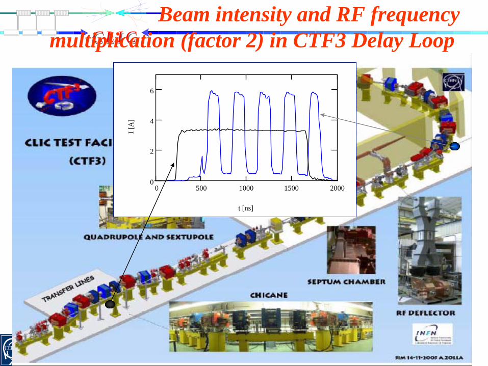
Beam intensity and RF frequency multiplication (factor 2) in CTF3 Delay Loop
0 500 1000 1500 20000
2
4
6
t [ns]
I [A
]
C L I CC L I C
J.P.Delahaye CLIC to RUPAC08 (29 – 09 – 08) 26
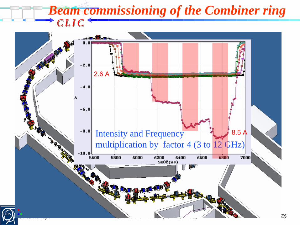
First circulating beam (May `07)
Beam commissioning of the Combiner ring
Intensity and Frequencymultiplication by factor 4 (3 to 12 GHz)
2.6 A
8.5 A
C L I CC L I C
J.P.Delahaye CLIC to RUPAC08 (29 – 09 – 08) 27
CLIC Experimental Area (CLEX)
Jan 2007Sept o7
- Test beam line (TBL) to study RF power production (2.5 TW at 12 GHz) and drive beam decelerator dynamics, stability & losses - Two Beam Test Stand to study probe beam acceleration with high fields at high frequency and the feasibility of Two Beam modules
existing building
D FFD
DF
F
D F DD F D
F
FD
D F D
D F D
DF DF DF DF DF DF DF DF DF
D F DF DF D
D FFFDD
DF
FDD
FF
FF
D F DD F DD F DD F D
F
FD
F
FD
F
FD
D F DD F D
D F DD F D
DF DF DF DF DF DF DF DF DF DFDF DF DF DF DF DF DF DF DF DF DF DF DF DF DF DF
D F DD F DF DF DF DF D
42.5 m
8 m
2m
D FFD
DF
F
D F DDUMPD F D
F
FD
ITB
1.85m
CALIFES Probe beam injectorLIL-ACSLIL-ACSLIL-ACSD F D
D F D
DFDUMP
0.75
1.4m
1
DUMP
22.4 mTBL
2.5m
Transport path
DUMP
DUMP 22 m2.0m
DF DF DF DF DF DF DF DF
3.0m3.0m6 m
D F DF DF D
16.5 mTBTS16 m
TL2’
42.5 m42.5 m
8 m8 m
2m2m
D FFFDD
DF
FDD
FF
FF
D F DD F DDUMPD F DD F D
F
FD
F
FD
F
FD
ITB
1.85m1.85m
CALIFES Probe beam injectorLIL-ACSLIL-ACSLIL-ACSLIL-ACSLIL-ACSLIL-ACSD F DD F D
D F DD F D
DF DFDUMP
0.75
1.4m1.4m
11
DUMP
22.4 m22.4 mTBL
2.5m2.5m
Transport path
DUMP
DUMP 22 m22 m2.0m2.0m
DF DF DF DF DF DF DF DFDF DF DF DF DF DF DF DF DF DF DF DF DF DF DF DF
3.0m3.0m3.0m3.0m6 m6 m
D F DD F DF DF DF DF D
16.5 m16.5 mTBTS16 m16 m
TL2’
Test Beam Line TBL
June 2006September 2006
Jan 2008
Jan 2008June 2008
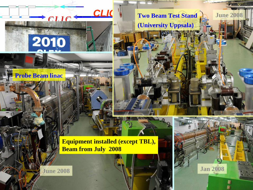
Probe Beam linac
June 2008Two Beam Test Stand(University Uppsala)
Equipment installed (except TBL),Beam from July 2008
C L I CC L I C
J.P.Delahaye CLIC to RUPAC08 (29 – 09 – 08) 28
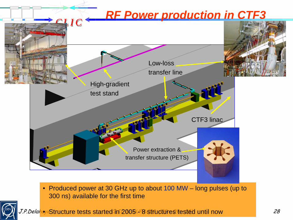
RF Power production in CTF3
CTF3 linac
Power extraction & transfer structure (PETS)
High-gradient test stand
Low-loss transfer line
• Produced power at 30 GHz up to about 100 MW – long pulses (up to 300 ns) available for the first time
• Structure tests started in 2005 - 8 structures tested until now

C L I CC L I C
J.P.Delahaye CLIC to RUPAC08 (29 – 09 – 08) 29
PETS parameters:Aperture = 23 mmPeriod = 6.253 mm (900/cell) Iris thickness = 2 mm R/Q = 2258 ΩV group= 0.453Q = 7200P/C = 13.4E surf. (135 MW)= 56 MV/mH surf. (135 MW) = 0.08
MA/m (∆T max (240 ns, Cu) = 1.8 C0)
To reduce the surface field concentration in the presence of the damping slot, the special profiling of the iris was adopted.
E-fieldH-field
In its final configuration, PETS comprises eight octants separated by the damping slots. Each of the slots is equipped with HOM damping loads. This arrangement follows the need to provide strong damping of the transverse modes.
CLIC Power Extraction and Transfer Structure (PETS)
I. Syratchev

C L I CC L I C
J.P.Delahaye CLIC to RUPAC08 (29 – 09 – 08) 30
TestingAcceleratingStructures

C L I CC L I C
J.P.Delahaye CLIC to RUPAC08 (29 – 09 – 08) 31
Improvement byRF conditionning
Nominal Structure Performance demonstrated
A shining example of fruitful collaboration:T18_VG2.4_disk: Designed at CERN,(without damping) Built at KEK,
RF Tested at SLAC
CLIC nominal
C L I CC L I C
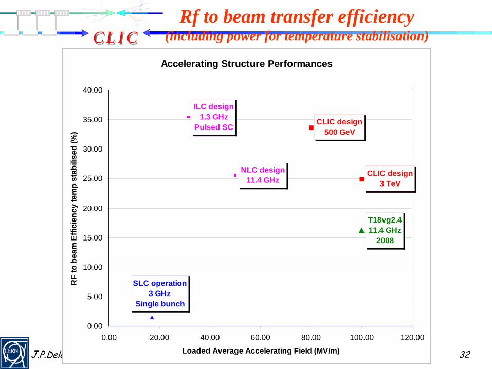
J.P.Delahaye CLIC to RUPAC08 (29 – 09 – 08) 32
Accelerating Structure Performances
ILC design1.3 GHz
Pulsed SC
SLC operation3 GHz
Single bunch
NLC design11.4 GHz
CLIC design3 TeV
CLIC design500 GeV
T18vg2.411.4 GHz
2008
0.00
5.00
10.00
15.00
20.00
25.00
30.00
35.00
40.00
0.00 20.00 40.00 60.00 80.00 100.00 120.00
Loaded Average Accelerating Field (MV/m)
RF
to b
eam
Effi
cien
cy te
mp
stab
ilise
d (%
)
Rf to beam transfer efficiency (including power for temperature stabilisation)
C L I CC L I C
J.P.Delahaye CLIC to RUPAC08 (29 – 09 – 08) 3333EPAC 2008 CLIC / CTF3 G.Geschonke, CERN
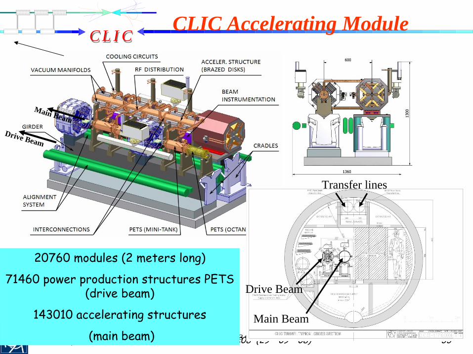
CLIC Accelerating Module
Drive Beam
Main Beam
Transfer lines
Main Beam
Drive Beam
20760 modules (2 meters long)
71460 power production structures PETS (drive beam)
143010 accelerating structures
(main beam)
C L I CC L I C
J.P.Delahaye CLIC to RUPAC08 (29 – 09 – 08) 34
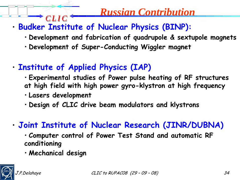
Russian Contribution•
Budker
Institute of Nuclear Physics (BINP):
•
Development and fabrication of quadrupole
& sextupole
magnets•
Development of Super-Conducting Wiggler magnet
•
Institute of Applied Physics (IAP)•
Experimental studies of Power pulse heating of RF structures
at high field with high power gyro-klystron at high frequency•
Lasers development
•
Design of CLIC drive beam modulators and klystrons
•
Joint Institute of Nuclear Research (JINR/DUBNA)•
Computer control of Power Test Stand and automatic RF
conditioning•
Mechanical design
C L I CC L I C
J.P.Delahaye CLIC to RUPAC08 (29 – 09 – 08) 35
CLIC08 workshop (14-17/10/08)
You are all kindly invited and welcome to participate
C L I CC L I C
J.P.Delahaye CLIC to RUPAC08 (29 – 09 – 08) 36
Conclusion
•
CLIC study well on track to address major issues and demonstrate feasibility including cost to be published in a Conceptual Design Report by 2010
•
CTF3 on schedule with installation completed (except TBL).•
Commissioning
under progress.
•
CLIC/CTF3 collaboration strong of 27 Institutes extremely fruitful and expanding
•
Excellent spirit of collaborative competition with ILC
•
Contribution of Russian Institutes warmly appreciated:•
Further participation on CLIC feasibility and technical design
welcome

C L I CC L I C
J.P.Delahaye CLIC to RUPAC08 (29 – 09 – 08) 37
Reserve slides

C L I CC L I C
J.P.Delahaye CLIC to RUPAC08 (29 – 09 – 08) 38
Relative cost of Linear Colliders
LC
CLIC
0
0 .5
1
1 .5
2
2 .5
3
3 .5
0 0 .2 0 .4 0 .6 0 .8 1 1 .2
Energy (arbitrary scale)
Cos
t (ar
bitr
ary
scal
e

C L I CC L I C
J.P.Delahaye CLIC to RUPAC08 (29 – 09 – 08) 39
28 MW
Main beam injection, magnets, services, infrastructure
and detector
Dumps
Mainlinac
PETS
Drive beamacceleration
252.6 MW
148.0 MW
137.4 MW
107.4 MW
13.7 MW ηplug/RF = 38.8 %
ηM = .90
ηA = .977
ηTRS = .98ηT = .96
F(σ)
= .97 ×
.96ηD = .84
Drive beampower extr.
Power suppliesklystrons
ηRF/main = 27.7 %
ηtot = 7.2 %
ηS = .95
ηRF = .277
101.1 MW (2 x 101 kJ x 50 Hz)
Main beam
Wall Plug
ηK = .70
389.2 MWModulator auxiliaries
260.4 MW
ηREL = .93aux = 0.97
128.8 MW
Power flow @ 3 TeV

C L I CC L I C
J.P.Delahaye CLIC to RUPAC08 (29 – 09 – 08) 4040EPAC 2008 CLIC / CTF3 G.Geschonke, CERN
Luminosity challenges >2*1034cm-2s-1) @ high energy (3 TeV)
Issues:• generating small emittance beams• emittance preservation• alignment and vibration control• final focus ( Beam Delivery System)
Beam size at Interaction Point (rms) : σx = 40 nm, σy = 1 nm
jitter tolerances
Final Focus quadrupoles
Main beam quadrupoles
Vertical ~0.2 nm > 4 Hz ~1 nm > 1 Hz
Horizontal 2 nm > 4 Hz 5 nm > 1 Hz
work ongoing,Proof-of-principle: quadrupole stabilized to < 0.5 nm in vertical plane

C L I CC L I C
J.P.Delahaye CLIC to RUPAC08 (29 – 09 – 08) 41
DG to CERN staffJan 08

C L I CC L I C
J.P.Delahaye CLIC to RUPAC08 (29 – 09 – 08) 42
Large Colliders Technically Driven Scenarii? A look into the crystal ball !
2007 2009 2010 2011 2012 2013 2014 2015 2016 2017 2018 2019 2020 2021 2022 2023 2024
LHC LHC Operation + LHC upgrade SLHC Operation
ILC
CLIC
R&D, Conceptual Design & Cost Estimation Commissioning & Operation
Technical design & industrialisation Construction (first stage)
Project approval & final cost
2008