c1 c2 - superior, colorado
TRANSCRIPT
C1C2
POINT OF CONNECTION:SEE I1.2
CONTROLLER LOCATION:SEE I1.2
1"
5
14.1
5
2"
6
37.6
6
2"
7
111
7
2"
8
86.1
8
2"
9
98.4
2"
10
92.5
10
2"
14
98.4
14
2"
15
96.1
15
2"
16
61.1
16
2"
17
86.4
17
2"
19
86.4
19
2"
20
86.4
20
2"
21
101
21
112"
22
23.5
22
2"
23
99.6
23
112" 23.5
24
24
2"
26
101
26
2"
27
112
27
2"
28
49.2
28
2"
29
86.4
29
2"
31
86.4
31
2"
32
83.0
2" 61.5
33
33
2"
34
98.4
34
2" 64.8
35
35
2" 85.0
40
40
2" 47.1
41
41 1" 5.52
42
42
2" 94.2
43
43
2" 62.8
45
45
2" 101
46
46
2" 111
48
48
2" 101
49
49
2" 99.6
50
50
2" 116
51
51
112" 23.5
53
53
2" 49.9
54
54
2" 50.7
57
57
2" 71.4
58
58
2"
2
75.7
2
1
2"
25
99.6
25
1"
3
-
3
1"
4
-
4
11
1"
12
-
12
1"
13
-
13
1"
18
-
18
1" -
30
30
38
1" -
39
39
1" -
44
44
1" -
47
1" -
52
52
1" -
55
55
1" -
56
56
2"
36
-
36
2"
37
-
37
MATCHLINE SEE I1.1
MATCHLINE SEE I1.2
MA
TCH
LIN
E S
EE
I1.1
MA
TCH
LIN
E S
EE
I1.2
MATCHLINE SEE I1.1
MATCHLINE SEE I1.2
MA
TCH
LIN
E S
EE
I1.1
MA
TCH
LIN
E S
EE
I1.2
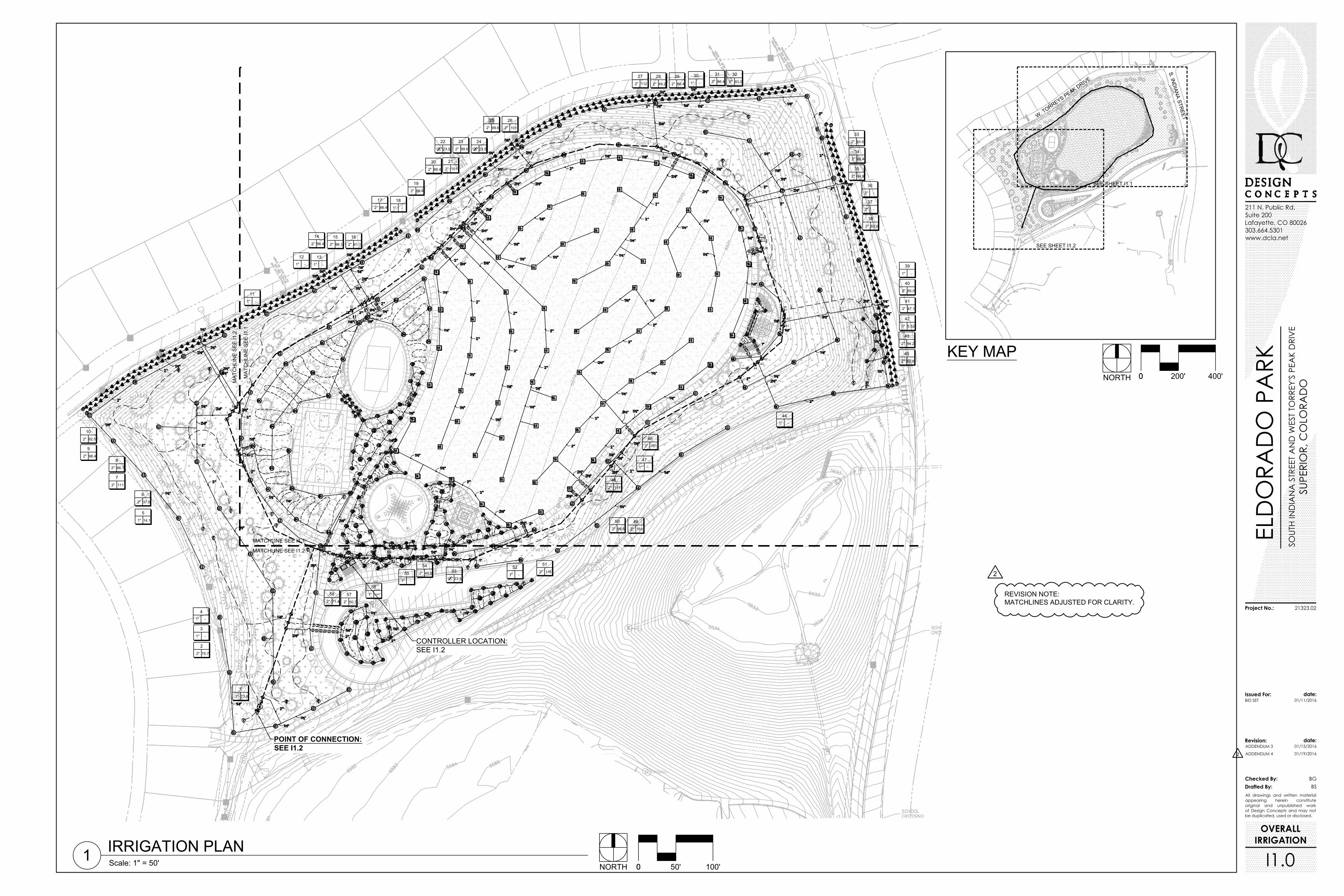
IRRIGATION PLAN1 Scale: 1" = 50' 00 50' 100'NORTH
ELD
ORA
DO
PA
RKSO
UTH
IND
IAN
A S
TREE
T A
ND
WES
T TO
RREY
'S P
EAK
DRI
VE
SUPE
RIO
R, C
OLO
RAD
O
BID SET
21323.02
All drawings and written materialappearing herein constituteoriginal and unpublished workof Design Concepts and may notbe duplicated, used or disclosed.
Issued For: date:
Revision: date:
Checked By:Drafted By:
Project No.:
01/11/2016
BGBS
211 N. Public Rd.Suite 200Lafayette, CO 80026303.664.5301www.dcla.net
ADDENDUM 3 01/15/2016
ADDENDUM 4 01/19/2016
OVERALLIRRIGATION
I1.0
KEY MAPNORTH 00 200' 400'
2
2
REVISION NOTE:MATCHLINES ADJUSTED FOR CLARITY.
1-6" SLEEVE1-4" SLEEVETYP FOR ALL MAINLINESLEEVE LOCATIONS
5
6
7
8
10
2"
14
98.4
14
2"
15
96.1
15
2"
16
61.1
16
2"
17
86.4
17
2"
19
86.4
19
2"
20
86.4
20
2"
21
101
21
112"
22
23.5
22
2"
23
99.6
23
112" 23.5
24
24
2"
26
101
26
2"
27
112
27
2"
28
49.2
28
2"
29
86.4
29
2"
31
86.4
31
2"
32
83.0
2" 61.5
33
33
2"
34
98.4
34
2" 64.8
35
35
2" 85.0
40
40
2" 47.1
41
41 1" 5.52
42
42
2" 94.2
43
43
2" 62.8
45
45
2" 101
46
46
2" 111
48
48
2" 101
49
49
2" 99.6
50
50
51
53
54
58
2"
25
99.6
25
11
1"
12
-
12
1"
13
-
13
1"
18
-
18
1" -
30
30
38
1" -
39
39
1" -
44
44
1" -
47
52
55
56
2"
36
-
36
2"
37
-
37
MATCHLINE SEE I1.1
MATCHLINE SEE I1.2
MA
TCH
LIN
E S
EE
I1.1
MA
TCH
LIN
E S
EE
I1.2
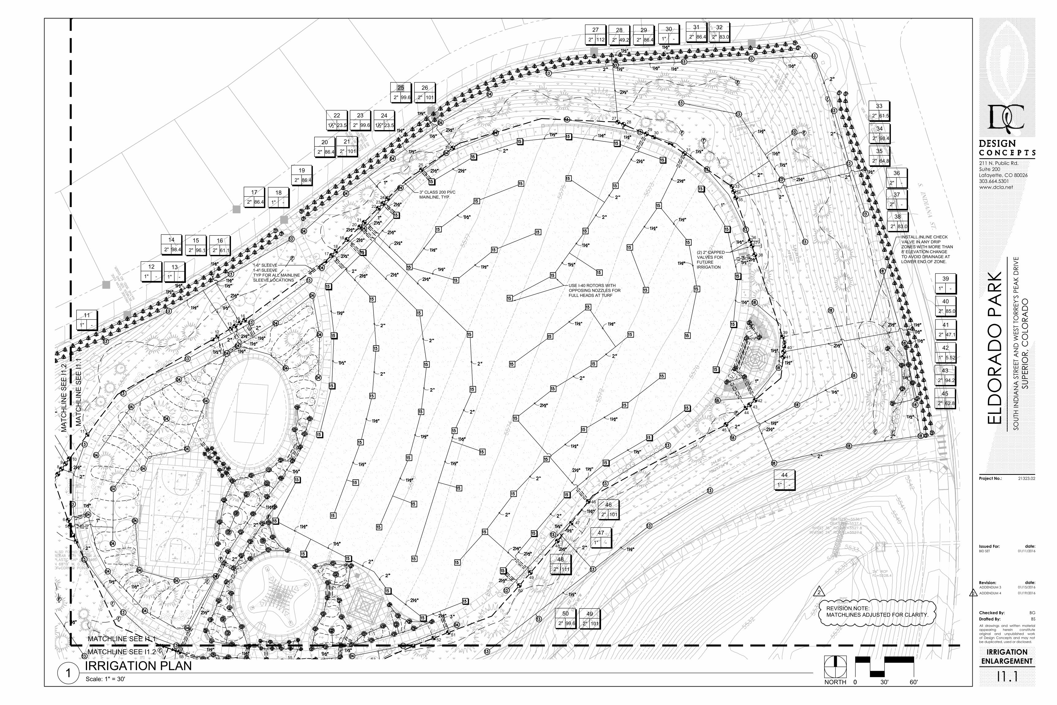
IRRIGATION PLAN1 Scale: 1" = 30' 00 30' 60'NORTH
ELD
ORA
DO
PA
RKSO
UTH
IND
IAN
A S
TREE
T A
ND
WES
T TO
RREY
'S P
EAK
DRI
VE
SUPE
RIO
R, C
OLO
RAD
O
BID SET
21323.02
All drawings and written materialappearing herein constituteoriginal and unpublished workof Design Concepts and may notbe duplicated, used or disclosed.
Issued For: date:
Revision: date:
Checked By:Drafted By:
Project No.:
01/11/2016
BGBS
211 N. Public Rd.Suite 200Lafayette, CO 80026303.664.5301www.dcla.net
ADDENDUM 3 01/15/2016
ADDENDUM 4 01/19/2016
IRRIGATIONENLARGEMENT
I1.1
2 2
REVISION NOTE:MATCHLINES ADJUSTED FOR CLARITY.
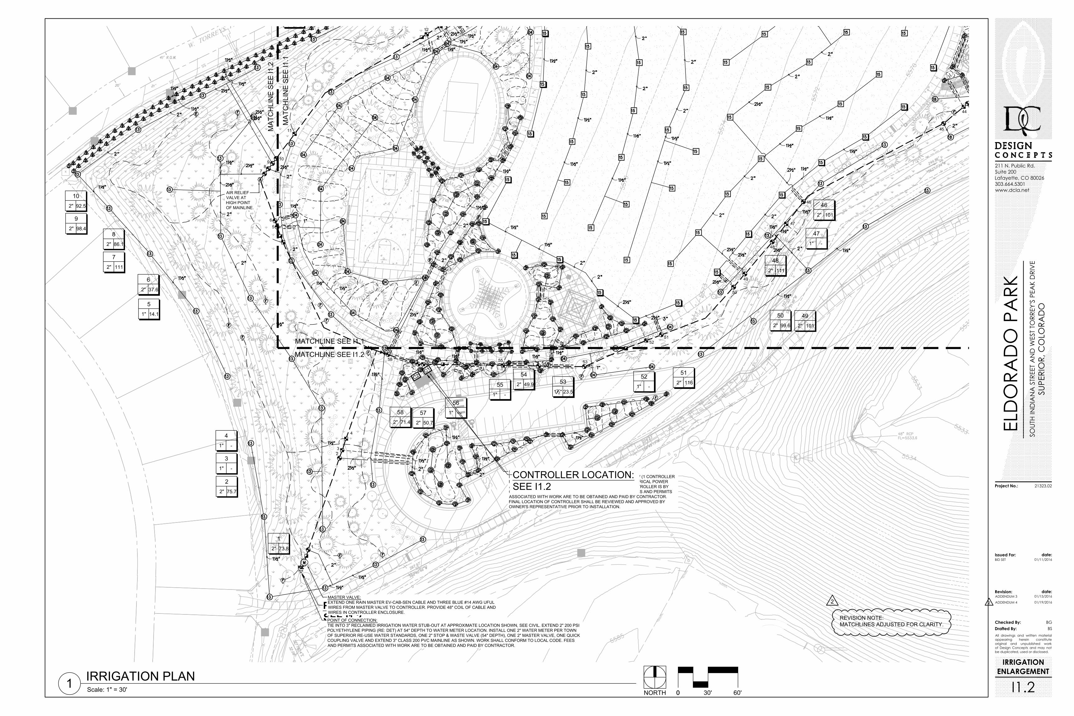
CONTROLLER:INSTALL CONTROLLERS INSIDE STRONGBOX MODEL: SB-24SSW (1 CONTROLLERPER ENCLOSURE) AT APPROXIMATE LOCATION SHOWN. ELECTRICAL POWERAND CONNECTION, INCLUDING ELECTRIC METER SET, TO CONTROLLER IS BYCONTRACTOR WITH WORK CONFORMING TO LOCAL CODE. FEES AND PERMITSASSOCIATED WITH WORK ARE TO BE OBTAINED AND PAID BY CONTRACTOR.FINAL LOCATION OF CONTROLLER SHALL BE REVIEWED AND APPROVED BYOWNER'S REPRESENTATIVE PRIOR TO INSTALLATION.
C1
C2
POINT OF CONNECTION:SEE I1.2
CONTROLLER LOCATION:SEE I1.2
1"
5
14.1
5
2"
6
37.6
6
2"
7
111
7
2"
8
86.1
8
2"
9
98.4
2"
10
92.5
10
45
2" 101
46
46
2" 111
48
48
2" 101
49
49
2" 99.6
50
50
2" 116
51
51
112" 23.5
53
53
2" 49.9
54
54
2" 50.7
57
57
2" 71.4
58
58
2"
2
75.7
2
1
POINT OF CONNECTION:TIE INTO 3" RECLAIMED IRRIGATION WATER STUB-OUT AT APPROXIMATE LOCATION SHOWN, SEE CIVIL. EXTEND 2" 200 PSIPOLYETHYLENE PIPING (RE: DET) AT 54" DEPTH TO WATER METER LOCATION. INSTALL ONE 2" WATER METER PER TOWNOF SUPERIOR RE-USE WATER STANDARDS, ONE 2" STOP & WASTE VALVE (54" DEPTH), ONE 2" MASTER VALVE, ONE QUICKCOUPLING VALVE AND EXTEND 3" CLASS 200 PVC MAINLINE AS SHOWN. WORK SHALL CONFORM TO LOCAL CODE. FEESAND PERMITS ASSOCIATED WITH WORK ARE TO BE OBTAINED AND PAID BY CONTRACTOR.
1"
3
-
3
1"
4
-
4
11
12
44
1" -
47
1" -
52
52
1" -
55
55
1" -
56
56
AIR RELIEFVALVE ATHIGH POINTOF MAINLINE.
MATCHLINE SEE I1.1
MATCHLINE SEE I1.2
MA
TCH
LIN
E S
EE
I1.1
MA
TCH
LIN
E S
EE
I1.2
IRRIGATION PLAN1 Scale: 1" = 30' 00 30' 60'NORTH
ELD
ORA
DO
PA
RKSO
UTH
IND
IAN
A S
TREE
T A
ND
WES
T TO
RREY
'S P
EAK
DRI
VE
SUPE
RIO
R, C
OLO
RAD
O
BID SET
21323.02
All drawings and written materialappearing herein constituteoriginal and unpublished workof Design Concepts and may notbe duplicated, used or disclosed.
Issued For: date:
Revision: date:
Checked By:Drafted By:
Project No.:
01/11/2016
BGBS
211 N. Public Rd.Suite 200Lafayette, CO 80026303.664.5301www.dcla.net
ADDENDUM 3 01/15/2016
ADDENDUM 4 01/19/2016
IRRIGATIONENLARGEMENT
I1.2
2 2
REVISION NOTE:MATCHLINES ADJUSTED FOR CLARITY.
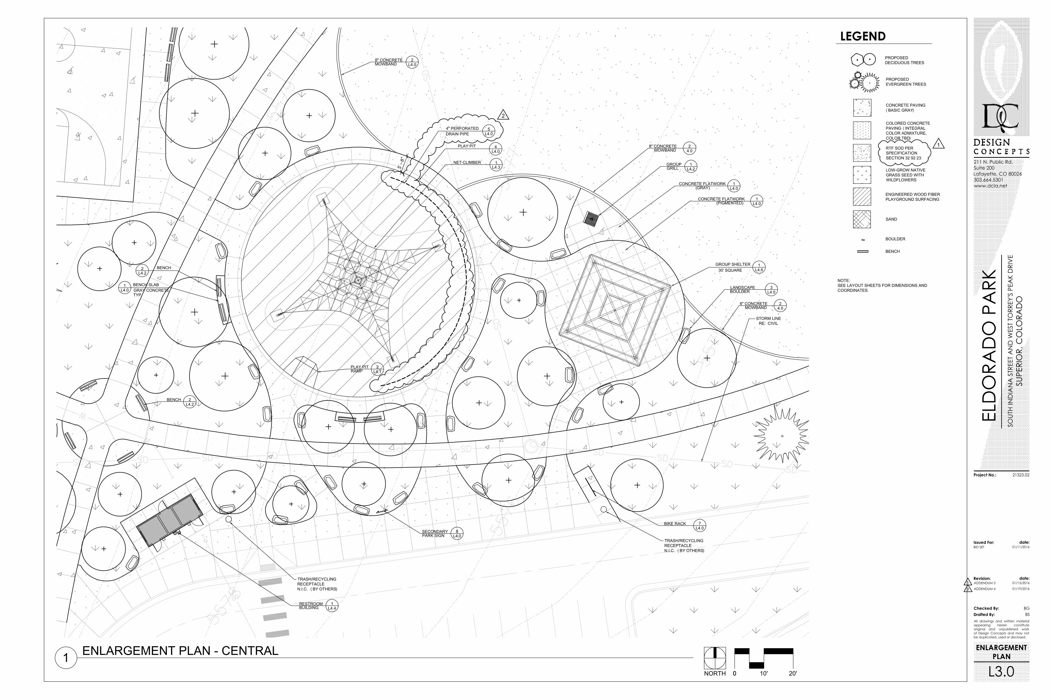
L4.03LANDSCAPE
BOULDER
L4.028" CONCRETE
MOWBAND
L4.61GROUP SHELTER
30' SQUARE
L4.01CONCRETE FLATWORK
(GRAY)
L4.07BIKE RACK
L4.08SECONDARY
PARK SIGN
L4.31NET CLIMBER
L4.04PLAY PIT
L4.22 BENCH
4.028" CONCRETE
MOWBAND
L4.12PLAY PIT
RAMP
L4.01CONCRETE FLATWORK
(PIGMENTED)
L4.22BENCH
4.028" CONCRETE
MOWBAND
L4.01 BENCH SLAB
GRAY CONCRETETYP.
L4.054" PERFORATED
DRAIN PIPE
ENLARGEMENT PLAN - CENTRAL100 10' 20'NORTH
ELD
ORA
DO
PA
RKSO
UTH
IND
IAN
A S
TREE
T A
ND
WES
T TO
RREY
'S P
EAK
DRI
VE
SUPE
RIO
R, C
OLO
RAD
O
BID SET
21323.02
All drawings and written materialappearing herein constituteoriginal and unpublished workof Design Concepts and may notbe duplicated, used or disclosed.
Issued For: date:
Revision: date:
Checked By:Drafted By:
Project No.:
01/11/2016
BGBS
211 N. Public Rd.Suite 200Lafayette, CO 80026303.664.5301www.dcla.net
ADDENDUM 3 01/15/2016
ADDENDUM 4 01/19/2016
ENLARGEMENTPLAN
L3.0
LEGEND
NOTE:SEE LAYOUT SHEETS FOR DIMENSIONS ANDCOORDINATES.
1
1
2
2
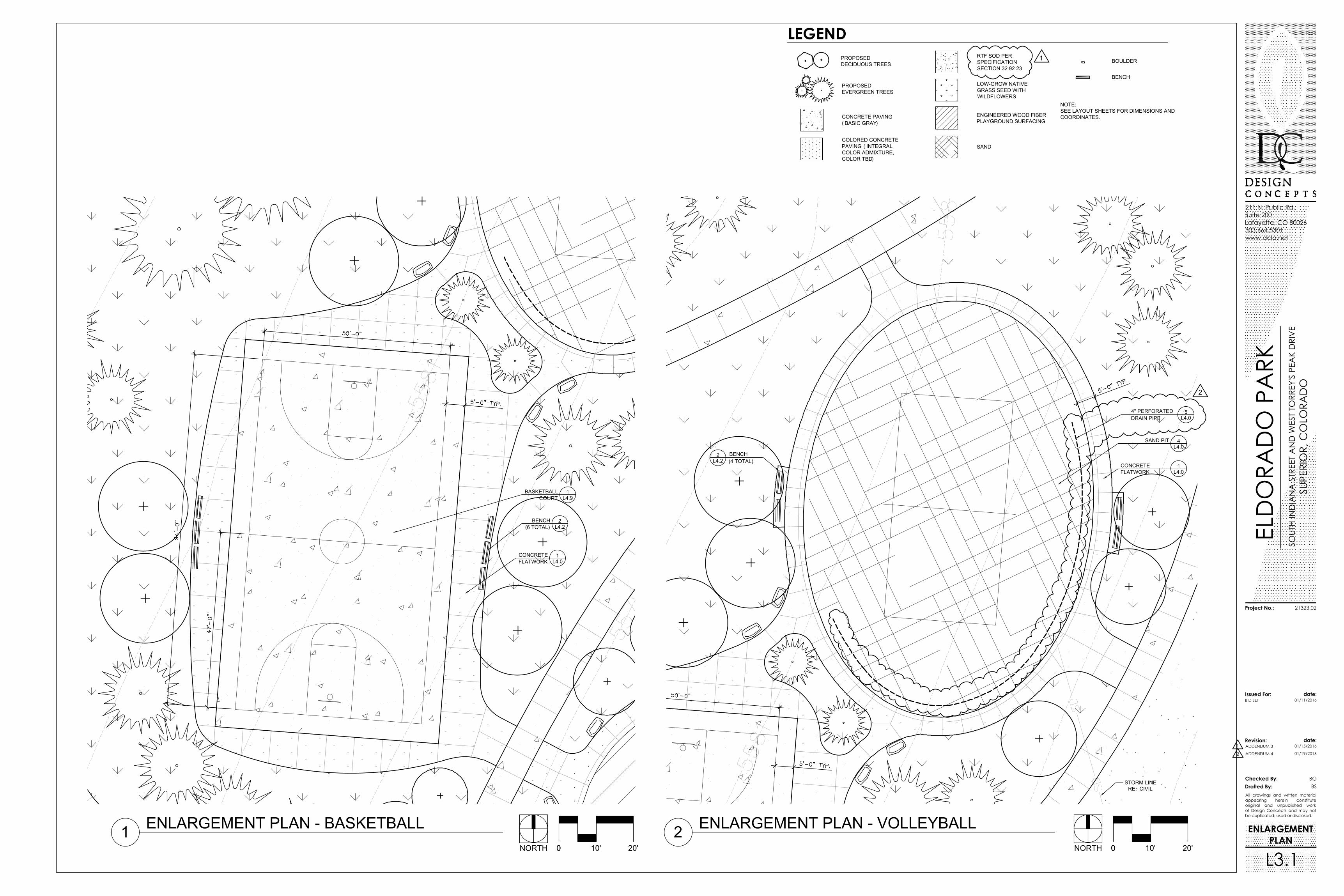
L4.01CONCRETE
FLATWORK
L4.22BENCH
(6 TOTAL)
L4.91BASKETBALL
COURT
L4.04SAND PIT
L4.01CONCRETE
FLATWORK
L4.22 BENCH
(4 TOTAL)
L4.054" PERFORATED
DRAIN PIPE
ENLARGEMENT PLAN - BASKETBALL100 10' 20'NORTH
ELD
ORA
DO
PA
RKSO
UTH
IND
IAN
A S
TREE
T A
ND
WES
T TO
RREY
'S P
EAK
DRI
VE
SUPE
RIO
R, C
OLO
RAD
O
BID SET
21323.02
All drawings and written materialappearing herein constituteoriginal and unpublished workof Design Concepts and may notbe duplicated, used or disclosed.
Issued For: date:
Revision: date:
Checked By:Drafted By:
Project No.:
01/11/2016
BGBS
211 N. Public Rd.Suite 200Lafayette, CO 80026303.664.5301www.dcla.net
ADDENDUM 3 01/15/2016
ADDENDUM 4 01/19/2016
ENLARGEMENT PLAN - VOLLEYBALL200 10' 20'NORTH
ENLARGEMENTPLAN
L3.1
LEGEND
NOTE:SEE LAYOUT SHEETS FOR DIMENSIONS ANDCOORDINATES.
1
1
2
2
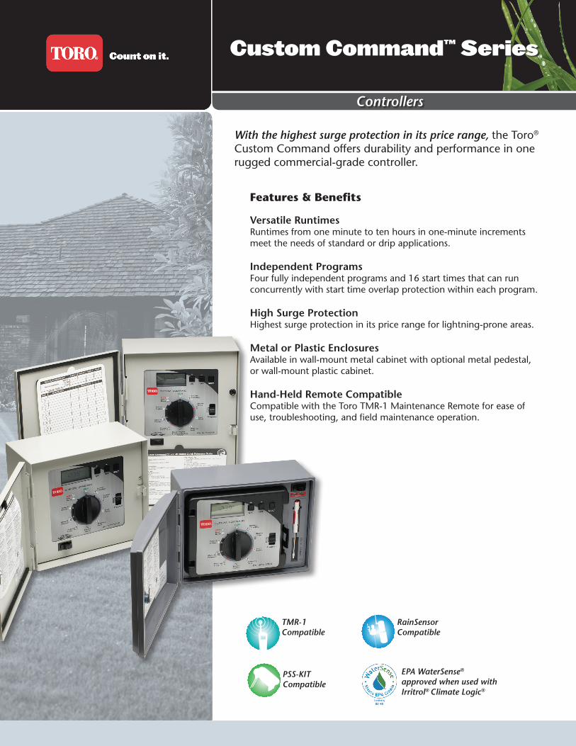
Controllers
Custom Command™ Series
PSS-KITCompatible
EPA WaterSense® approved when used with Irritrol® Climate Logic®
Features & Benefits
Versatile RuntimesRuntimes from one minute to ten hours in one-minute increments meet the needs of standard or drip applications.
Independent ProgramsFour fully independent programs and 16 start times that can run concurrently with start time overlap protection within each program.
High Surge ProtectionHighest surge protection in its price range for lightning-prone areas.
Metal or Plastic EnclosuresAvailable in wall-mount metal cabinet with optional metal pedestal, or wall-mount plastic cabinet.
Hand-Held Remote CompatibleCompatible with the Toro TMR-1 Maintenance Remote for ease of use, troubleshooting, and field maintenance operation.
With the highest surge protection in its price range, the Toro® Custom Command offers durability and performance in one rugged commercial-grade controller.
TMR-1Compatible
RainSensorCompatible
Custom Command™ Series
www.toro.com • The Toro Company • Irrigation Division • 5825 Jasmine St. • Riverside, CA • 92504 • 877-345-8676Specifications subject to change without notice. For more information, contact your local Toro distributor. P/N 13-1106-IRC©2013 The Toro Company. All rights reserved.
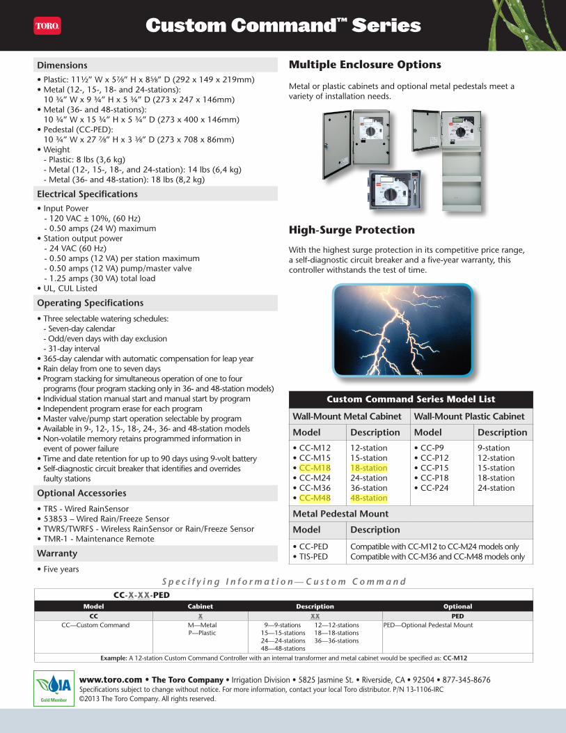
Dimensions• Plastic: 11½” W x 57⁄8” H x 85⁄8” D (292 x 149 x 219mm)• Metal (12-, 15-, 18- and 24-stations):
10 ¾” W x 9 ¾” H x 5 ¾” D (273 x 247 x 146mm)• Metal (36- and 48-stations):
10 ¾” W x 15 ¾” H x 5 ¾” D (273 x 400 x 146mm)• Pedestal (CC-PED):
10 ¾” W x 27 7⁄8” H x 3 3⁄8” D (273 x 708 x 86mm)• Weight
- Plastic: 8 lbs (3,6 kg) - Metal (12-, 15-, 18-, and 24-station): 14 lbs (6,4 kg) - Metal (36- and 48-station): 18 lbs (8,2 kg)
Electrical Specifications• Input Power - 120 VAC ± 10%, (60 Hz) - 0.50 amps (24 W) maximum• Station output power - 24 VAC (60 Hz) - 0.50 amps (12 VA) per station maximum - 0.50 amps (12 VA) pump/master valve - 1.25 amps (30 VA) total load• UL, CUL Listed
Operating Specifications
• Three selectable watering schedules: - Seven-day calendar - Odd/even days with day exclusion - 31-day interval• 365-day calendar with automatic compensation for leap year• Rain delay from one to seven days• Program stacking for simultaneous operation of one to four programs (four program stacking only in 36- and 48-station models)• Individual station manual start and manual start by program• Independent program erase for each program• Master valve/pump start operation selectable by program• Available in 9-, 12-, 15-, 18-, 24-, 36- and 48-station models• Non-volatile memory retains programmed information in event of power failure• Time and date retention for up to 90 days using 9-volt battery• Self-diagnostic circuit breaker that identifies and overrides faulty stations
Optional Accessories
• TRS - Wired RainSensor• 53853 – Wired Rain/Freeze Sensor• TWRS/TWRFS - Wireless RainSensor or Rain/Freeze Sensor• TMR-1 - Maintenance Remote
Warranty
• Five years
With the highest surge protection in its competitive price range, a self-diagnostic circuit breaker and a five-year warranty, this controller withstands the test of time.
Multiple Enclosure Options
High-Surge Protection
Metal or plastic cabinets and optional metal pedestals meet a variety of installation needs.
Custom Command Series Model List
Wall-Mount Metal Cabinet Wall-Mount Plastic Cabinet
Model Description Model Description
• CC-M12 • CC-M15 • CC-M18 • CC-M24 • CC-M36 • CC-M48
12-station 15-station18-station24-station36-station48-station
• CC-P9 • CC-P12 • CC-P15• CC-P18• CC-P24
9-station 12-station15-station18-station24-station
Metal Pedestal Mount
Model Description
• CC-PED • TIS-PED
Compatible with CC-M12 to CC-M24 models onlyCompatible with CC-M36 and CC-M48 models only
S p e c i f y i n g I n f o r m a t i o n — C u s t o m C o m m a n d CC-X-XX-PED
Model Cabinet Description OptionalCC X XX PED
CC—Custom Command M—MetalP—Plastic
9—9-stations 12—12-stations15—15-stations 18—18-stations24—24-stations 36—36-stations48—48-stations
PED—Optional Pedestal Mount
Example: A 12-station Custom Command Controller with an internal transformer and metal cabinet would be specified as: CC-M12