c40-20 industrial pump instructions, service manual …€¦ · · 2011-05-17c40-20 industrial...
TRANSCRIPT
123833A632
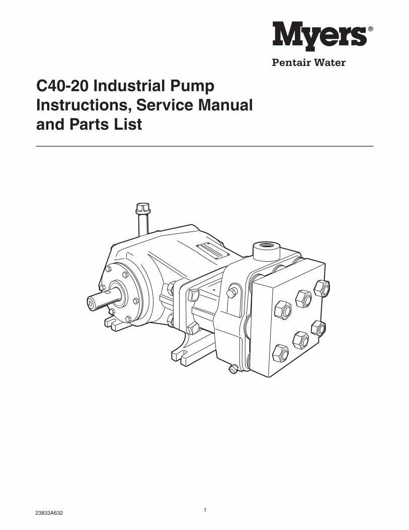
C40-20 Industrial PumpInstructions, Service Manualand Parts List

223833A632
FLUID END
DIMENSIONS
BODYHigh strength ductileiron.
SUCTION,DISCHARGEOPENINGSThreaded for easyconnections.
CYLINDERSTapered stainless steel linerswith ceramic oxide coating.
PISTON ASSEMBLYSolid stainless steel stud,pressure ring, spring, retainerand cap screw.
BODYRugged cast gray ironcrankcase serves as oilreservoir. Removable coversection for easy service.
CRANKSHAFTRotates in either direction.Automotive-type heat-treated alloy steel.
MAIN BEARINGSTapered rollerbearings.
CONTINUOUS SPLASHLUBRICATIONIn either rotation direction.
CONNECTING LINKSCast ductile iron withreplaceable bronzebearings.
CROSSHEADSHeavy-duty ductile iron.Extension rods are axiallythreaded and pinned,polished stainless steel.
PACKINGNitrile with cotton fabric.Multi-lip V-ring supportedby brass follower.
VALVE ASSEMBLIESAll stainless steel.Spring-loaded valves,hardened seats.
VALVE & CYLINDERCAPSBuna-N O-rings andback-up ring.
221/16"
69/32" 125/16"
1111/16"
31/64"
Oil Fill
1" NPTDischarge
5/16" x 5/32"Key way
103/4"
5"
Oil Drain 27/8"
101/4"
121/2"
35/16" 15/8"2" NPTSuction
1.3750 dia.
1.3745
57/16"3/4" 57/16"
121/8"
31/8"
10"
167/8"
(4) Slots 9/16 wide x 15/16 long for 1/2 bolts
323833A632
INSTRUCTIONSCAUTION - Positive displacement pumps must have aproper size and operable type of pressure regulatingvalve or pressure relief valve piped into the dischargeline. This is mandatory to prevent damage to pumpand piping or possible injury to personnel. Do notinstall any valves or shut-off devices in the bypass linefrom pressure regulator to tank or supply.
It is recommended to install a pulsation dampener indischarge line to smooth out pressure pulse. This canprotect pump parts and piping for longer life and quietoperation.
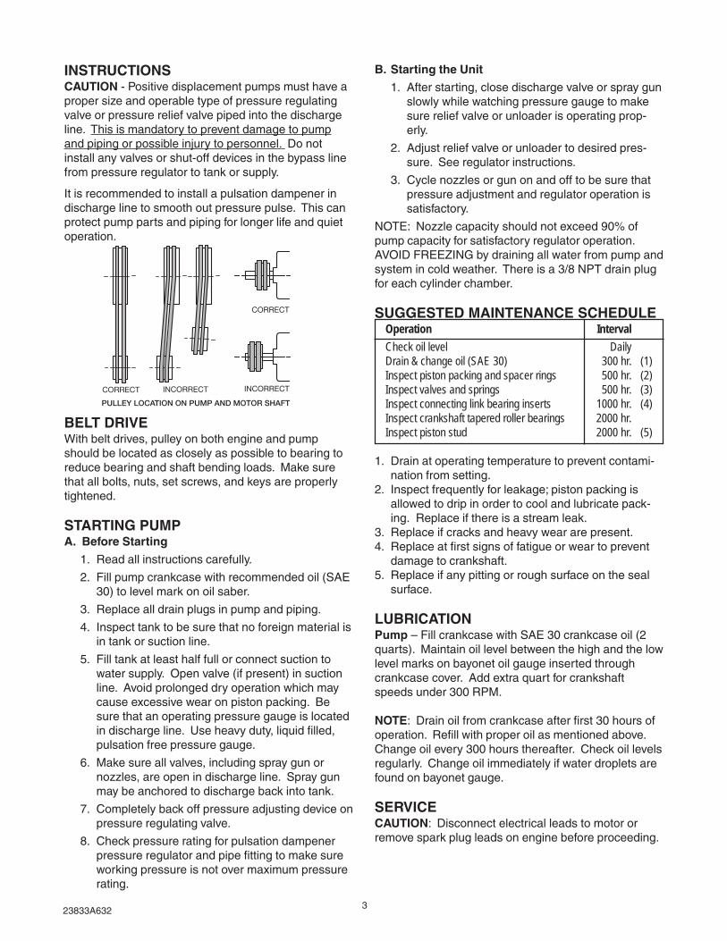
BELT DRIVEWith belt drives, pulley on both engine and pumpshould be located as closely as possible to bearing toreduce bearing and shaft bending loads. Make surethat all bolts, nuts, set screws, and keys are properlytightened.
STARTING PUMPA. Before Starting
1. Read all instructions carefully.
2. Fill pump crankcase with recommended oil (SAE30) to level mark on oil saber.
3. Replace all drain plugs in pump and piping.
4. Inspect tank to be sure that no foreign material isin tank or suction line.
5. Fill tank at least half full or connect suction towater supply. Open valve (if present) in suctionline. Avoid prolonged dry operation which maycause excessive wear on piston packing. Besure that an operating pressure gauge is locatedin discharge line. Use heavy duty, liquid filled,pulsation free pressure gauge.
6. Make sure all valves, including spray gun ornozzles, are open in discharge line. Spray gunmay be anchored to discharge back into tank.
7. Completely back off pressure adjusting device onpressure regulating valve.
8. Check pressure rating for pulsation dampenerpressure regulator and pipe fitting to make sureworking pressure is not over maximum pressurerating.
B. Starting the Unit
1. After starting, close discharge valve or spray gunslowly while watching pressure gauge to makesure relief valve or unloader is operating prop-erly.
2. Adjust relief valve or unloader to desired pres-sure. See regulator instructions.
3. Cycle nozzles or gun on and off to be sure thatpressure adjustment and regulator operation issatisfactory.
NOTE: Nozzle capacity should not exceed 90% ofpump capacity for satisfactory regulator operation.AVOID FREEZING by draining all water from pump andsystem in cold weather. There is a 3/8 NPT drain plugfor each cylinder chamber.
SUGGESTED MAINTENANCE SCHEDULEOperation Interval
Check oil level DailyDrain & change oil (SAE 30) 300 hr. (1)Inspect piston packing and spacer rings 500 hr. (2)Inspect valves and springs 500 hr. (3)Inspect connecting link bearing inserts 1000 hr. (4)Inspect crankshaft tapered roller bearings 2000 hr.Inspect piston stud 2000 hr. (5)
1. Drain at operating temperature to prevent contami-nation from setting.
2. Inspect frequently for leakage; piston packing isallowed to drip in order to cool and lubricate pack-ing. Replace if there is a stream leak.
3. Replace if cracks and heavy wear are present.4. Replace at first signs of fatigue or wear to prevent
damage to crankshaft.5. Replace if any pitting or rough surface on the seal
surface.
LUBRICATIONPump – Fill crankcase with SAE 30 crankcase oil (2quarts). Maintain oil level between the high and the lowlevel marks on bayonet oil gauge inserted throughcrankcase cover. Add extra quart for crankshaftspeeds under 300 RPM.
NOTE: Drain oil from crankcase after first 30 hours ofoperation. Refill with proper oil as mentioned above.Change oil every 300 hours thereafter. Check oil levelsregularly. Change oil immediately if water droplets arefound on bayonet gauge.
SERVICECAUTION: Disconnect electrical leads to motor orremove spark plug leads on engine before proceeding.
CORRECT
INCORRECTCORRECT INCORRECT
PULLEY LOCATION ON PUMP AND MOTOR SHAFT

423833A632
23
4
1
17124A00017123B000M1666A000
05027A011
PISTONROD
CYLINDERBODY
CYLINDER LINER
REPLACING PISTON PACKINGLoosen cap screw (59) and piston assembly can beremoved through cylinder opening. Use waterproofgrease to lubricate piston packing and o-ring oncylinder caps.
REPLACING CYLINDER LINERSRemoval: (See Figure 1)1. First remove piston packing as outlined previously.2. Rotate crankshaft until piston rod is in rear position.3. Insert puller (3) through inside of cylinder.4. Insert disc (4) into slots on puller (3).5. Slip plate (2) over threads on puller (3) as shown.6. Screw nut (1) on thread in puller (3) and snug up.7. Tighten nut (1) until liner breaks loose.8. Loosen nut (1) and slip disc (4) out of slots.9. Remove puller (3) and repeat to remove remainder
of cylinder liners.
CYLINDER LINER REMOVAL TOOL KIT(17123B001K)
INSTALLATIONReasonable care and judgment should be used wheninstalling the new tapered cylinder liner. Clean out anyaccumulation of loose rust or corrosion in taperedcylinder. Inspect o-ring. Replace it if damaged. Insertliner in position by hand and drive into position firmly(but not excessively) with a wood block and mallet.Never use a hand or hydraulic arbor press to installcylinder liner. It is possible to shrink the liner.
REPLACING PISTON ROD SEALS
The rod seal assembly (see Figure 2) contains two oilseals with lips facing power end. The oil seal can bereplaced without taking the fluid end off by removingthe cylinder and piston to allow access for oil sealhousing. Unscrew two Allen screws and place into theother two tapped holes. Gradually screw them in topush oil seal housing off the retainer. After assemblingnew seals in oil seal housing an assembly thimbleshould be used on end of crosshead rod for sliding oilseal housing back into retainer. Check gasket, replaceif damaged.
An assembly thimble should be used on small end ofthe piston rod to expand sealing edge as it is pushedon. Figure 3 shows a recommended thimble forinstallation of oil seals. The thimble should be ma-chined from high carbon steel and polished on theexterior to reduce possibility of seal lip damage.
SERVICING CRANKCASE PARTSTo remove the crankshaft you do not need to removethe cylinder body from the crankcase. Remove theconnecting link caps from the connecting links andpush the free links toward the cylinder end as far aspossible. The crankshaft can then be removed bytaking off the bearing caps and pulling the crankshaftthrough the bearing opening as shown in illustrationFigure 4. During this process be sure to note themarkings on the connecting links and link caps be-cause these parts are mated to each other and shouldbe reinstalled in the same position they were beforetaken apart.
PowerEndSide
FluidEndSide
11/4”
1/16”R
9/16”DIA.
5/8”
1/32”R
.880 DIA.
.875.485 DIA..480
Figure 1
Figure 2
Figure 3
Figure 4
523833A632
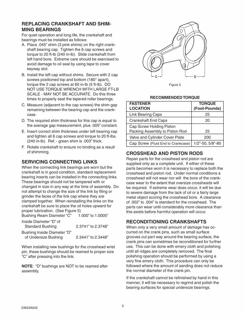
REPLACING CRANKSHAFT AND SHIM-MING BEARINGSFor quiet operation and long life, the crankshaft andbearings must be installed as follows:A. Place .045” shim (3 pink shims) on the right crank-
shaft bearing cap. Tighten the 6 cap screws andtorque to 20 ft-lb (240 in-lb). Slide crankshaft fromleft hand bore. Extreme care should be exercised toavoid damage to oil seal by using tape to coverkeyway slot.
B. Install the left cap without shims. Secure with 2 capscrews positioned top and bottom (180° apart),torque the 2 cap screws at 60 in-lb (5 ft-lb). DONOT USE TORQUE WRENCH WITH LARGE FT-LBSCALE - MAY NOT BE ACCURATE. Do this threetimes to properly seat the tapered roller bearings.
C. Measure (adjacent to the cap screws) the shim gapremaining between the bearing cap and the crank-case.
D. The required shim thickness for this cap is equal tothe average gap measurement, plus .005” constant.
E. Insert correct shim thickness under left bearing capand tighten all 6 cap screws and torque to 20 ft-lbs.(240 in-lb). Ref. - green shim is .003” thick.
F. Rotate crankshaft to ensure no binding as a resultof shimming.
SERVICING CONNECTING LINKSWhen the connecting link bearings are worn but thecrankshaft is in good condition, standard replacementbearing inserts can be installed in the connecting links.These bearings should not be tampered with orchanged in size in any way at the time of assembly. Donot attempt to change the size of the link by filing orgrinder the faces of the link cap where they areclamped together. When reinstalling the links on thecrankshaft be sure to place the oil holes upward forproper lubrication. (See Figure 5)Bushing Ream Diameter “C” 1.000” to 1.0005”
Inside Diameter “D” of Standard Bushing 2.3741” to 2.3748”
Bushing Inside Diameter “D” of Undersize Bushing 2.3441” to 2.3448”
When installing new bushings for the crosshead wristpin, these bushings should be reamed to proper size“C” after pressing into the link.
NOTE: “D” bushings are NOT to be reamed afterassembly.
RECOMMENDED TORQUE
FASTENER TORQUELOCATION (Foot-Pounds)
Link Bearing Caps 25
Crankshaft End Caps 20
Cap Screw Holding PistonPacking Assembly to Piston Rod 25
Valve and Cylinder Cover Plate 200
Cap Screw (Fluid End to Crankcase) 1/2”-50, 5/8”-80
CROSSHEAD AND PISTON RODSRepair parts for the crosshead and piston rod aresupplied only as a complete unit. If either of theseparts becomes worn it is necessary to replace both thecrosshead and piston rod. Under normal conditions acrosshead will not wear nor will the bore of the crank-case wear to the extent that oversize crossheads willbe required. If extreme wear does occur, it will be dueto severe damage from the lack of oil or a fairly largemetal object scoring the crosshead bore. A clearanceof .002” to .004” is standard for the crosshead. Theparts can wear until considerably more clearance thanthis exists before harmful operation will occur.
RECONDITIONING CRANKSHAFTSWhen only a very small amount of damage has oc-curred on the crank pins, such as small surfacegrooves cut part way around the bearing surface, thecrank pins can sometimes be reconditioned for furtheruse. This can be done with emery cloth and polishinguntil all ridges are completely removed. The finalpolishing operation should be performed by using avery fine emery cloth. This procedure can only befollowed where the amount of sanding does not reducethe normal diameter of the crank pin.
If the crankshaft cannot be refinished by hand in thismanner, it will be necessary to regrind and polish thebearing surfaces for special undersize bearings.
Figure 5
623833A632
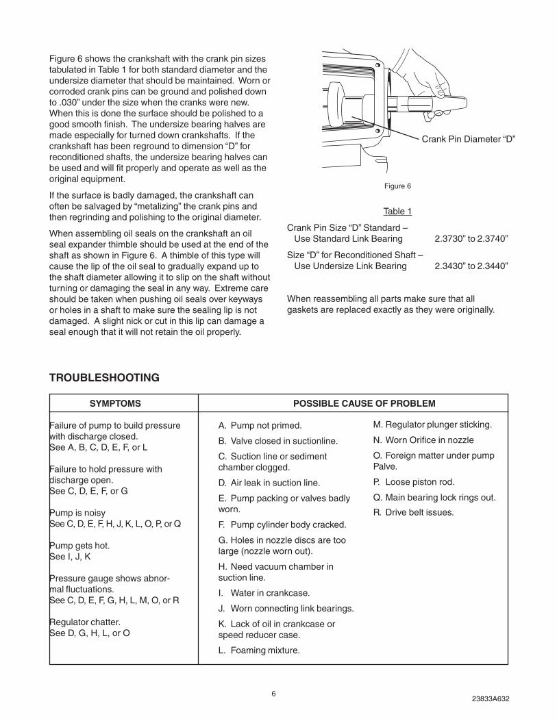
Figure 6 shows the crankshaft with the crank pin sizestabulated in Table 1 for both standard diameter and theundersize diameter that should be maintained. Worn orcorroded crank pins can be ground and polished downto .030” under the size when the cranks were new.When this is done the surface should be polished to agood smooth finish. The undersize bearing halves aremade especially for turned down crankshafts. If thecrankshaft has been reground to dimension “D” forreconditioned shafts, the undersize bearing halves canbe used and will fit properly and operate as well as theoriginal equipment.
If the surface is badly damaged, the crankshaft canoften be salvaged by “metalizing” the crank pins andthen regrinding and polishing to the original diameter.
When assembling oil seals on the crankshaft an oilseal expander thimble should be used at the end of theshaft as shown in Figure 6. A thimble of this type willcause the lip of the oil seal to gradually expand up tothe shaft diameter allowing it to slip on the shaft withoutturning or damaging the seal in any way. Extreme careshould be taken when pushing oil seals over keywaysor holes in a shaft to make sure the sealing lip is notdamaged. A slight nick or cut in this lip can damage aseal enough that it will not retain the oil properly.
SYMPTOMS
Failure of pump to build pressurewith discharge closed.See A, B, C, D, E, F, or L
Failure to hold pressure withdischarge open.See C, D, E, F, or G
Pump is noisySee C, D, E, F, H, J, K, L, O, P, or Q
Pump gets hot.See I, J, K
Pressure gauge shows abnor-mal fluctuations.See C, D, E, F, G, H, L, M, O, or R
Regulator chatter.See D, G, H, L, or O
A. Pump not primed.
B. Valve closed in suctionline.
C. Suction line or sedimentchamber clogged.
D. Air leak in suction line.
E. Pump packing or valves badlyworn.
F. Pump cylinder body cracked.
G. Holes in nozzle discs are toolarge (nozzle worn out).
H. Need vacuum chamber insuction line.
I. Water in crankcase.
J. Worn connecting link bearings.
K. Lack of oil in crankcase orspeed reducer case.
L. Foaming mixture.
Table 1
Crank Pin Size “D” Standard – Use Standard Link Bearing 2.3730” to 2.3740”
Size “D” for Reconditioned Shaft – Use Undersize Link Bearing 2.3430” to 2.3440”
When reassembling all parts make sure that allgaskets are replaced exactly as they were originally.
TROUBLESHOOTING
POSSIBLE CAUSE OF PROBLEM
Figure 6
M. Regulator plunger sticking.
N. Worn Orifice in nozzle
O. Foreign matter under pumpPalve.
P. Loose piston rod.
Q. Main bearing lock rings out.
R. Drive belt issues.
Crank Pin Diameter “D”
723833A632
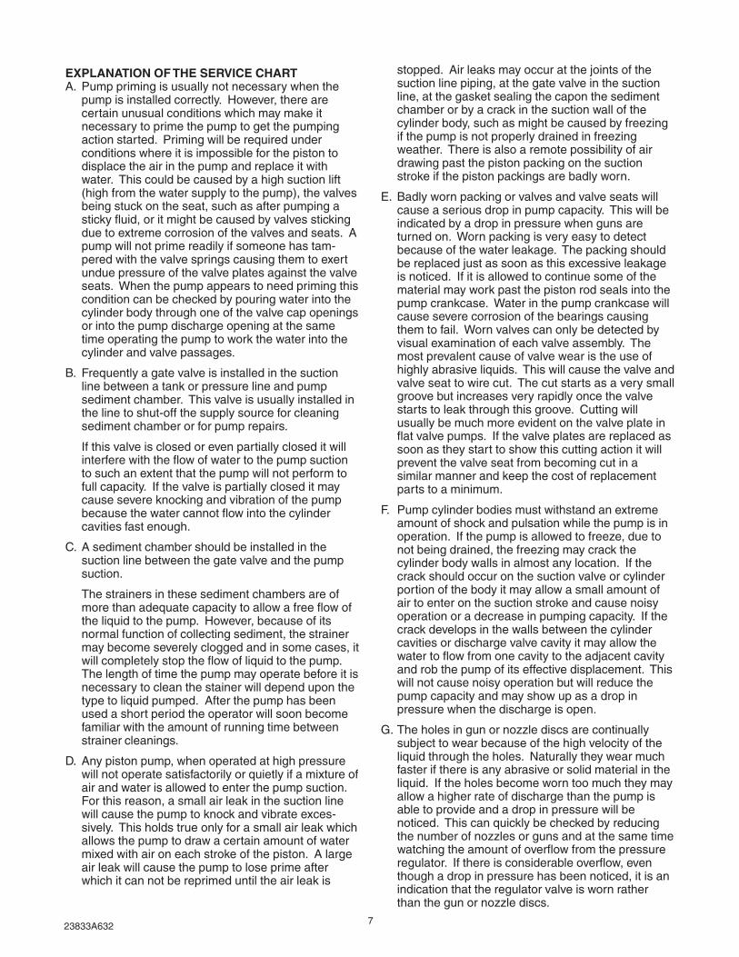
EXPLANATION OF THE SERVICE CHARTA. Pump priming is usually not necessary when the
pump is installed correctly. However, there arecertain unusual conditions which may make itnecessary to prime the pump to get the pumpingaction started. Priming will be required underconditions where it is impossible for the piston todisplace the air in the pump and replace it withwater. This could be caused by a high suction lift(high from the water supply to the pump), the valvesbeing stuck on the seat, such as after pumping asticky fluid, or it might be caused by valves stickingdue to extreme corrosion of the valves and seats. Apump will not prime readily if someone has tam-pered with the valve springs causing them to exertundue pressure of the valve plates against the valveseats. When the pump appears to need priming thiscondition can be checked by pouring water into thecylinder body through one of the valve cap openingsor into the pump discharge opening at the sametime operating the pump to work the water into thecylinder and valve passages.
B. Frequently a gate valve is installed in the suctionline between a tank or pressure line and pumpsediment chamber. This valve is usually installed inthe line to shut-off the supply source for cleaningsediment chamber or for pump repairs.
If this valve is closed or even partially closed it willinterfere with the flow of water to the pump suctionto such an extent that the pump will not perform tofull capacity. If the valve is partially closed it maycause severe knocking and vibration of the pumpbecause the water cannot flow into the cylindercavities fast enough.
C. A sediment chamber should be installed in thesuction line between the gate valve and the pumpsuction.
The strainers in these sediment chambers are ofmore than adequate capacity to allow a free flow ofthe liquid to the pump. However, because of itsnormal function of collecting sediment, the strainermay become severely clogged and in some cases, itwill completely stop the flow of liquid to the pump.The length of time the pump may operate before it isnecessary to clean the stainer will depend upon thetype to liquid pumped. After the pump has beenused a short period the operator will soon becomefamiliar with the amount of running time betweenstrainer cleanings.
D. Any piston pump, when operated at high pressurewill not operate satisfactorily or quietly if a mixture ofair and water is allowed to enter the pump suction.For this reason, a small air leak in the suction linewill cause the pump to knock and vibrate exces-sively. This holds true only for a small air leak whichallows the pump to draw a certain amount of watermixed with air on each stroke of the piston. A largeair leak will cause the pump to lose prime afterwhich it can not be reprimed until the air leak is
stopped. Air leaks may occur at the joints of thesuction line piping, at the gate valve in the suctionline, at the gasket sealing the capon the sedimentchamber or by a crack in the suction wall of thecylinder body, such as might be caused by freezingif the pump is not properly drained in freezingweather. There is also a remote possibility of airdrawing past the piston packing on the suctionstroke if the piston packings are badly worn.
E. Badly worn packing or valves and valve seats willcause a serious drop in pump capacity. This will beindicated by a drop in pressure when guns areturned on. Worn packing is very easy to detectbecause of the water leakage. The packing shouldbe replaced just as soon as this excessive leakageis noticed. If it is allowed to continue some of thematerial may work past the piston rod seals into thepump crankcase. Water in the pump crankcase willcause severe corrosion of the bearings causingthem to fail. Worn valves can only be detected byvisual examination of each valve assembly. Themost prevalent cause of valve wear is the use ofhighly abrasive liquids. This will cause the valve andvalve seat to wire cut. The cut starts as a very smallgroove but increases very rapidly once the valvestarts to leak through this groove. Cutting willusually be much more evident on the valve plate inflat valve pumps. If the valve plates are replaced assoon as they start to show this cutting action it willprevent the valve seat from becoming cut in asimilar manner and keep the cost of replacementparts to a minimum.
F. Pump cylinder bodies must withstand an extremeamount of shock and pulsation while the pump is inoperation. If the pump is allowed to freeze, due tonot being drained, the freezing may crack thecylinder body walls in almost any location. If thecrack should occur on the suction valve or cylinderportion of the body it may allow a small amount ofair to enter on the suction stroke and cause noisyoperation or a decrease in pumping capacity. If thecrack develops in the walls between the cylindercavities or discharge valve cavity it may allow thewater to flow from one cavity to the adjacent cavityand rob the pump of its effective displacement. Thiswill not cause noisy operation but will reduce thepump capacity and may show up as a drop inpressure when the discharge is open.
G. The holes in gun or nozzle discs are continuallysubject to wear because of the high velocity of theliquid through the holes. Naturally they wear muchfaster if there is any abrasive or solid material in theliquid. If the holes become worn too much they mayallow a higher rate of discharge than the pump isable to provide and a drop in pressure will benoticed. This can quickly be checked by reducingthe number of nozzles or guns and at the same timewatching the amount of overflow from the pressureregulator. If there is considerable overflow, eventhough a drop in pressure has been noticed, it is anindication that the regulator valve is worn ratherthan the gun or nozzle discs.

823833A632
H. Suction surge arresters should be installed on thesuction line of reciprocating pumps. A rubber bagtype of suction surge arrester is preferred by asuitable vacuum chamber can be made by attachinga piece of vertical pipe as close to the pump suctionas possible. One and one-half or two inch pipe canbe used. A standing height of 12” to 15” will besufficient with the top end closed by an ordinarypipe cap.
I. Water may accumulate in the pump crankcase fromtwo sources; the most prevalent being leakage ofthe packing as explained in Paragraph E. The othermeans of accumulation being a condensation ofmoisture inside the crankcase due to changes inweather of the repeated heating and cooling of thepump due to its normal usage. Pumps that areused rather consistently and urn for a considerableperiod of time to heat the oil and other working partswill not normally accumulate water by condensation.If the packing is replaced as soon as it starts to leakit will be impossible for water to enter the crankcasefrom this cause. In localities or conditions whereextremely abrasive liquids must be used, it is alwaysadvisable to replace the cylinder shells at the sametime the worn packing is replaced. New packing willnot give satisfactory service if it is placed in a badlyworn and roughened cylinder liner.
J. Worn connecting link bearings will only developbecause of unusual or adverse operating conditions.They will, however, be seriously affected by corro-sion if water is present in the crankcase and theywill wear out from overheating if adequate oil is notprovided in the crankcase. For this reason werecommend thorough draining, cleaning and refillingwith new oil prior to any storage period. Replacebearings as soon as any damage is discovered toavoid possible damage to crankshaft. (See Lubrica-tion Instructions.)
K. Lack of sufficient oil in crankcase can quickly causefailure of pump power end and result in extensiverepairs. Oil level should be checked periodicallyduring normal operation as well as when mainte-nance work of any nature is performed. Insufficientoil will first be indicated by excessive heat andshould be corrected immediately.
L. A foaming mixture will sometimes have the sameeffect as a small air leak in the suction line. This isbecause various quantities of the foam is drawnthrough the suction line into the pump disrupting thenormal flow of water.
M. Pressure regulators that are operated by pistonaction may become sluggish in action due to thepiston sticking or fitting too tightly in its cylinder.This condition may be caused by an accumulationof chemicals collecting in and around the piston,or may be due to excessive corrosion of the pistonparts. To check this condition, remove and cleanthe piston. After cleaning the piston, parts shouldbe covered with a waterproof grease beforeassembling.
N. In some cases there is a tendency for the pressureregulator valves to chatter or vibrate excessively.This is an indication of unstable operation due tonozzling in the high or low capacity range of theregulator. On systems using pressure regulatorvalves, the nozzling requirements should be at least50% and not exceed 90% of pump capacity. Due tonozzle disc wear, the system requirements mayexceed the 90% limit, resulting in cycling or ham-mering of the regulator. This can readily be checkedby replacing the worn discs with new discs.
O. If a large piece of foreign matter becomes lodgedbetween a pump valve and valve seat or if some-thing of this kind becomes wedged in so that itprevents the valve from operating normally we canexpect drastic drop in capacity and considerablesurge or pulsation will be noticed in the dischargeline. To correct a condition of this kind it is usuallynecessary to examine each valve in the pump untilthe offending condition is located. The use of cleanliquid and seeing that the suction strainer is inproper condition will prevent trouble of this kind.
P. Noisy pump operation will sometimes be caused bya piston rod being loose in the crosshead. This willonly become evident after the rod becomes soextremely loose that some end motion can be foundbetween the piston rod and crosshead. A noise ofthis kind usually has a regular cadence timed witheach stroke of the piston. When this conditionoccurs it is always necessary to replace both thepiston rod and the crosshead because the two partsare threaded and pinned into a single unit.
Q. The crankshaft main bearings are held in place bythe end bearing caps. If bearing cap retaining boltsshould become loosened, the bearing can shiftwhich may cause bearing to run exceptionally hot.
UNUSUAL CONDITIONS WHICH MAYCAUSE TROUBLE
R. If the V-belts have a tendency to wear rapidly, it maybe due to having the belt tightener pulley adjustedtoo far into the belt, throwing a reverse bend in thebelt where it passes over the pulley. If very muchreverse angle seems necessary to keep the belttight, other provisions should be made for tighten-ing, such as placing shims under the pump base orotherwise spreading the drive centers enough totake up the belt length. On multiple V-belt drives, acomplete set of belts should be installed whenmaking a replacement. Further, all the belts in oneset should be checked for length and accuratelymatched to avoid placing an undue load on any onebelt. The synchronized belt can deliver highertorque with narrower belt. The sprocket is thusnarrower which results in less bending movementon main bearing and crankshaft.

923833A632
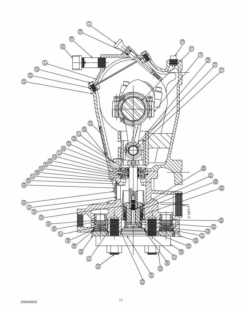
Ref. No. Description Qty. Part Number
1 Washer, Seal 12 14946A0032 Screw, Cap, 3/8-16 12 19101A0133 O-Ring, 4 3/8 O.D. 2 05876A2404 Key, Square, 5/16 x 5/16 1 05818A0775 Crankshaft 1 06074D0166 Seal, Oil, 1 3/8 Shaft 1 05710A0047 Cap, Bearing, Open 1 10414B002
8A Gasket, Shim, .003", Green 6 05011A0278B Gasket, Shim, .005", Pink 4 05011A0289 Bearing, Cup 2 05675A01810 Bearing, Cone 2 05674A01911 Cap, Bearing, Closed 1 10414B00112 Pin, Wrist 3 06116A00013 Crosshead & Piston Rod 3 17515B00114 Link 3 27300B000
14A Bushing 3 06108B000K15* Bearing, Steel-Backed Half 6 06109A00016 Plug, Pipe, Magnetic 1 17481A00117 Gauge, oil Level 1 17360A01418 O-Ring 1 110-000110-20119 Nipple, Pipe 1 17995A00120 Cap, Pipe 1 05737A02121 Lid 1 06077C00022 Screw, Cap, Hex, 3/8-16 6 19101A00723 Gasket 1 06089B00024 Case, Gear 1 06076D00025 Plate, Name 1 06008A37426 Screw, Drive 4 05160A00427 Bolt, Square, 5/8-11 4 19108A02728 U-Cup 6 22835A00429 Retainer, Oil Seal Housing 3 24958A00130 O-Ring, 2 1/2 O.D. 3 05876A22431 Gasket, Vellumoid, 2 15/16 O.D. 3 05059A05232 Gasket, Vellumoid, 1.80 O.D. 3 05059A43533 Spring, Retainer 3 06120A00034 Housing, Oil Seal 3 24959A00235 Screw, Cap, Socket Head 6 06106A03436 Washer, Lock, 1/4" 4 05454A01137 Nut, Hex, 5/8-11 4 19109A04138 Screw, Cap, Hex, 1/2-13 4 19103A00839 Washer, 5/16 I.D. 2 05030A02040 Screw, Machine, 1/4-20 2 05028A00241 Lid, Body, Cylinder 1 06123A00042 Body, Cylinder 1 18790E00643 Liner, Cylinder, 2.00 I.D. 3 06124A004
* Undersized (.030 dia.) Bearings are 10877A010K (2 Halves)
Model C40-20 Parts List

1023833A632
Ref. No Description Qty. Part Number
45 Seat, Valve 6 06125A00446 Valve, Delrin 6 17714A00347 Spring, Valve, Discharge 3 06127A00348 O-Ring, 1 7/16 O.D. 6 05876A17149 Ring, Back-Up, Nitrile 6 18753A00850 Cap, Valve 6 18456A00751 Gasket, Nylon 6 05059A43652 Stud, 7/8-14UNF 6 05659A13053 Gasket, Nylon 3 05059A43754 Cap, SST Cylinder 3 18457A00855 Nut, Hex ST 7/8-14 NF 6 19109A07256 Ring, Back-Up, Nitrile 3 18753A00957 O-Ring, 2 7/16 O.D. 3 05876A17358 Plate, Steel 1 26980B00059 Screw, Cap, Hex, Nylock 3 17050A00460 Plug, Pipe, Brass 3/8" NPT 4 06136A00061 Retainer, Spring, SST 3 18879A00462 Spring, Valve, Suction 3 06127A00263 Spring, SST 3 18920A00064 Ring, Pressure, SST 3 18921A00065 Packing, V-Ring, 2.00 O.D. 3 18922A00066 Follower, Brass 3 18923A00267 Stud, Piston 3 20850A00468 Washer, Copper 3 05030A128
Model C40-20 Parts List (continued)
11 109 7
6
5
4
3
2
1
8B8A
1123833A632
3938
47
46
45
43
4241
40
3736
3534
3332
3130
29
2827
26
48
49
50
51
52
53
54
56
55
57
58
59
60
61
62
63
6465
6667
68
12
13
14A
14
15
16
17
18
19
20
21
22
23
24
25
2” N
PT
1223833A632
MYERS/APLEXLIMITED WARRANTY
INDUSTRIAL PRODUCTSCENTRIFUGAL AND RECIPROCATING PUMPS
MYERS/APLEX warrants that its products are free from defects in material and workmanship for a period oftwelve (12) months from the date of purchase or eighteen (18) months from the date of manufacture.
During the warranty period and subject to the conditions hereinafter set forth, MYERS/APLEX, will repair orreplace to the original user or consumer parts which prove defective due to defective materials or workmanship ofMYERS/APLEX. Contact your nearest authorized MYERS/APLEX distributor or MYERS/APLEX for warrantyservice. At all times, MYERS/APLEX shall have and possess the sole right and option to determine whether torepair or replace defective equipment, parts or components..
WARRANTY EXCEPTIONS: Seals, piston cups, packing, plungers, liners, valves are covered for a period ofninety (90) days for ambient temperature water service. All other applications are for a period of thirty (30) daysunless specific written guarantee for that specific application is made by MYERS/APLEX . All engines, motors,auxiliary equipment are warranted only to the extent of the warranty given by the respective manufacturer.
LABOR, ETC. COSTS: MYERS/APLEX shall IN NO EVENT be responsible or liable for the cost of field labor orother charges incurred by any customer in removing and/or reaffixing any MYERS/APLEX product, part orcomponent thereof.
THIS WARRANTY WILL NOT APPLY: (a) to defects or malfunctions resulting from failure to properly install,operate or maintain the unit in accordance with printed instructions provided; (b) to failures resulting from abuse,accident or negligence; (c) to normal maintenance services and the parts used in connection with such service;(d) to units which are not installed in accordance with applicable local codes, ordinances and good trade prac-tices; or (e) if the unit is moved from its original installation location and (f) unit is used for purposes other than forwhat it was designed and manufactured.
RETURN OR REPLACED COMPONENTS: any item to be replaced under this Warranty must be returned toMYERS/APLEX in Ashland, Ohio, or such other place as MYERS/APLEX may designate, freight prepaid.
PRODUCT IMPROVEMENTS: MYERS/APLEX reserves the right to change or improve its products or anyportions thereof without being obligated to provide such a change or improvement for units sold and/or shippedprior to such a change or improvement.
WARRANTY EXCLUSIONS: MYERS/APLEX MAKES NO EXPRESS OR IMPLIED WARRANTIES WHICHEXTEND BEYOND THE DESCRIPTION ON THE FACE HEREOF. MYERS/APLEX SPECIFICALLY DISCLAIMSTHE IMPLIED WARRANTIES OF MERCHANTABILITY AND FITNESS FOR ANY PARTICULAR PURPOSE.
Some states do not permit some or all of the above warranty limitations and, therefore, such limitations may notapply to you. No warranties or representations at any time made by any representatives of Myers/Aplex shall varyor expand the provision hereof.
LIABILITY LIMITATION: IN NO EVENT SHALL MYERS/APLEX BE LIABLE OR RESPONSIBLE FOR CONSE-QUENTIAL, INCIDENTAL OR SPECIAL DAMAGES RESULTING FROM OR RELATED IN ANY MANNER TOANY MYERS/APLEX PRODUCT OR PARTS THEREOF. PERSONAL INJURY AND/OR PROPERTY DAMAGEMAY RESULT FROM IMPROPER INSTALLATION. MYERS/APLEX DISCLAIMS ALL LIABILITY, INCLUDINGLIABILITY UNDER THIS WARRANTY, FOR IMPROPER INSTALLATION -- MYERS/APLEX RECOMMENDSINSTALLATION BY PROFESSIONALS.
Some states do not allow the exclusion or limitation of incidental or consequential damages, so the abovelimitation or exclusion may not apply to you.
This Warranty gives you specific legal rights and you may also have other rights which vary from state to state.
In the absence of suitable proof of this purchase date, the effective date of this warranty will be based upon thedate of manufacture.
1101 Myers Parkway, Ashland, Ohio 44805-1969419/289-1144, FAX: 419/289-6658
1/08