cable trench installation guide - nv energy · 2020-01-01 · cable trench installation guide...
TRANSCRIPT

CABLE TRENCH INSTALLATION GUIDE GI0011U
CABLE TRENCH INSTALLATION GUIDE
1.0 INDEX
1.0 INDEX 2.0 PURPOSE 3.0 GENERAL INFORMATION 4.0 PLANNING INFORMATION 5.0 CREW INFORMATION 6.0 CONTRACTOR INFORMATION 7.0 PRECASTED/ POURED-IN-PLACE TRENCH DRAWINGS
2.0 PURPOSE
This standard provides information for construction of Cable Trench. This installation is for underground services from 2001 amps to 4000 amps.
3.0 GENERAL INFORMATION
3.1 Cable Trench is suitable for the following conditions: • 2001 Amp to 4000 amp services. • Trench length should be limited to 20 feet, with the service cable length limited to less than 50'
from transformer to customer panel.
4.0 PLANNING INFORMATION
VOLUME 17 – ENGINERING & CONSTRUCTION STANDARD
GI0011U CABLE TRENCH INSTALLATION GUIDE
Drawn: Eng: Appr: Date: Revision: 10 JVV MB DA 3/19 Page 1 of 12
CABLE TRENCH INSTALLATION GUIDE GI0011U
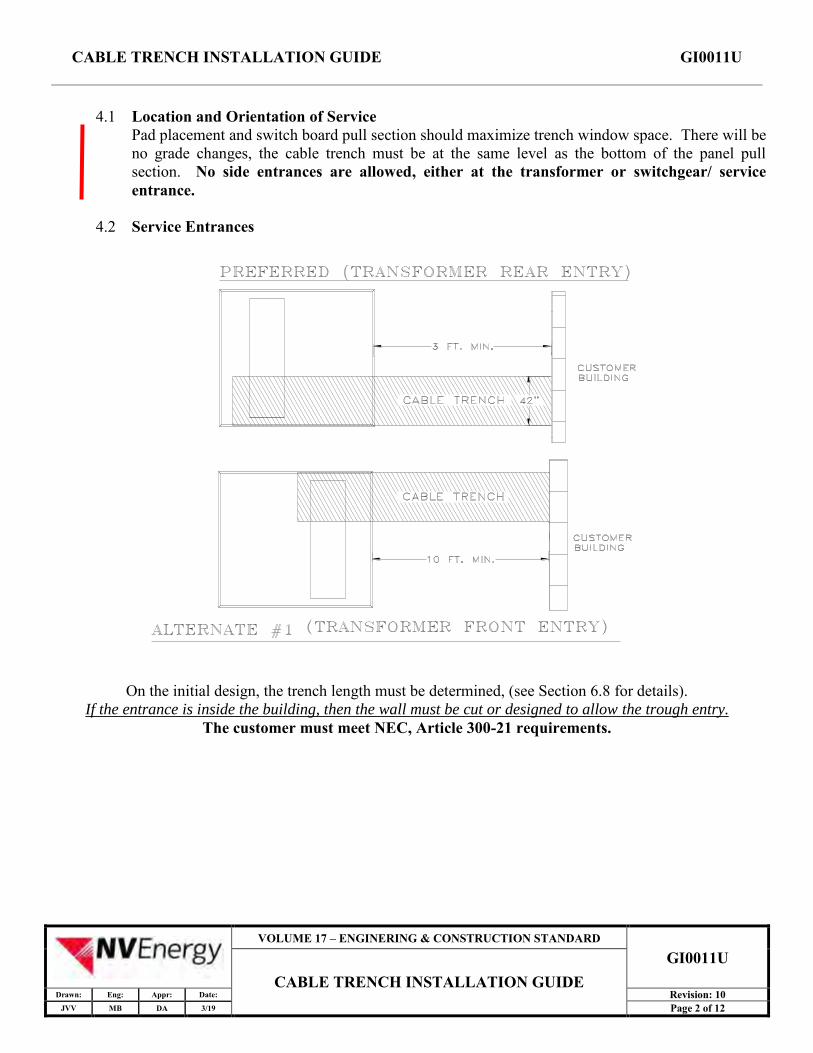
4.1 Location and Orientation of Service Pad placement and switch board pull section should maximize trench window space. There will be no grade changes, the cable trench must be at the same level as the bottom of the panel pull section. No side entrances are allowed, either at the transformer or switchgear/ service entrance.
4.2 Service Entrances
On the initial design, the trench length must be determined, (see Section 6.8 for details). If the entrance is inside the building, then the wall must be cut or designed to allow the trough entry.
The customer must meet NEC, Article 300-21 requirements.
VOLUME 17 – ENGINERING & CONSTRUCTION STANDARD
GI0011U CABLE TRENCH INSTALLATION GUIDE
Drawn: Eng: Appr: Date: Revision: 10 JVV MB DA 3/19 Page 2 of 12
CABLE TRENCH INSTALLATION GUIDE GI0011U
VOLUME 17 – ENGINERING & CONSTRUCTION STANDARD
GI0011U CABLE TRENCH INSTALLATION GUIDE
Drawn: Eng: Appr: Date: Revision: 10 JVV MB DA 3/19 Page 3 of 12
CABLE TRENCH INSTALLATION GUIDE GI0011U
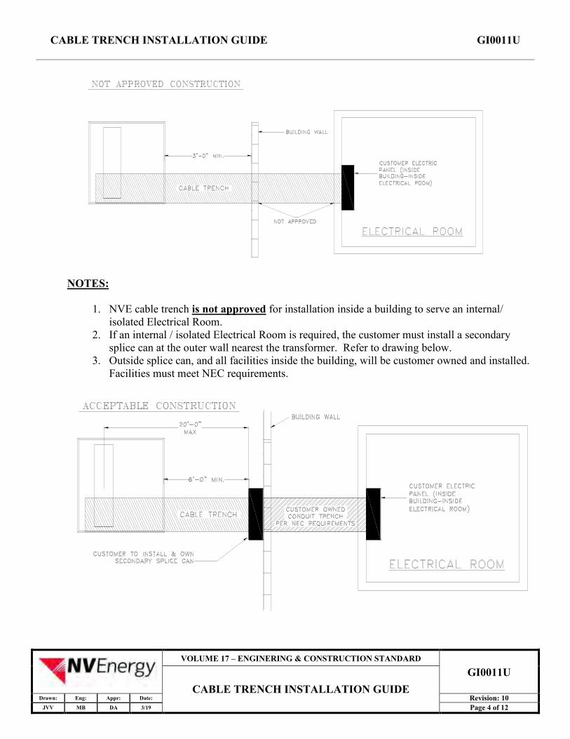
NOTES:
1. NVE cable trench is not approved for installation inside a building to serve an internal/ isolated Electrical Room.
2. If an internal / isolated Electrical Room is required, the customer must install a secondary splice can at the outer wall nearest the transformer. Refer to drawing below.
3. Outside splice can, and all facilities inside the building, will be customer owned and installed. Facilities must meet NEC requirements.
VOLUME 17 – ENGINERING & CONSTRUCTION STANDARD
GI0011U CABLE TRENCH INSTALLATION GUIDE
Drawn: Eng: Appr: Date: Revision: 10 JVV MB DA 3/19 Page 4 of 12

CABLE TRENCH INSTALLATION GUIDE GI0011U
4.3 Trench Covers There are two types of trench covers available: • H-20 Full Traffic Rated • Non-Traffic / Pedestrian Only
4.4 Cable Selection Multiple runs of cable will be required to serve the load. The number of runs depends upon the main panel rating. Number of cables per phase is based on 80% rated panels. Add extra set(s) if 100% panel, noted by ( ) in table.
MAIN PANEL RATING NUMBER OF CABLES PER PHASE 2001-2500 Amps 5 (6)
3000 Amps 6 (7) 3500 Amps 6 (8) 4000 Amps 7 (9)
See Table 8 of CB0003U, Vol. 17, Section 4, for cable ratings.
4.5 Required Service Materials (to be supplied by NVE)
ITEM STOCK NUMBER QUANITY
750 KCM 1 conductor 600 Volt Cable (Phase) 23-0895 See Section 4.4
350 KCM 1 conductor 600 Volt Cable (Neutral) 23-0781 See Section 4.4
750 KCM Flat-to-Crimp Connectors (bolt set). Stackable lug: 25-1315.
25-1356 (25-2693) 6 connectors per cable run
350 KCM Flat-to-Crimp Connectors (bolt set). Stackable lug: 25-1313
25-1351 (25-2697) 2 connectors per cable run
Cable Ties 95-8084 1 pkg. per 10' trench length
VOLUME 17 – ENGINERING & CONSTRUCTION STANDARD
GI0011U CABLE TRENCH INSTALLATION GUIDE
Drawn: Eng: Appr: Date: Revision: 10 JVV MB DA 3/19 Page 5 of 12
CABLE TRENCH INSTALLATION GUIDE GI0011U
5.0 CREW INFORMATION
5.1 Cable Orientation Cable Ties are to be set at +/- 15" intervals along the cable run. Each cable run contains 3 different phases and a neutral.
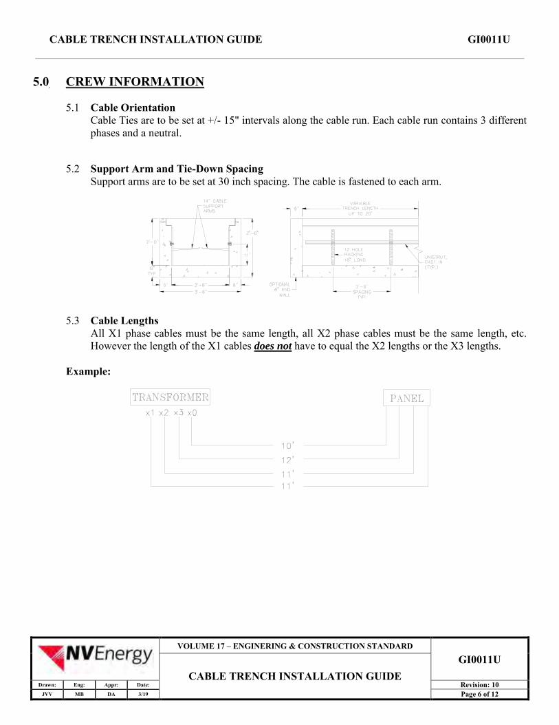
5.2 Support Arm and Tie-Down Spacing Support arms are to be set at 30 inch spacing. The cable is fastened to each arm.
5.3 Cable Lengths All X1 phase cables must be the same length, all X2 phase cables must be the same length, etc. However the length of the X1 cables does not have to equal the X2 lengths or the X3 lengths.
Example:
VOLUME 17 – ENGINERING & CONSTRUCTION STANDARD
GI0011U CABLE TRENCH INSTALLATION GUIDE
Drawn: Eng: Appr: Date: Revision: 10 JVV MB DA 3/19 Page 6 of 12

CABLE TRENCH INSTALLATION GUIDE GI0011U
6.0 CONTRACTOR INFORMATION
6.1 Contractor Responsibility The contractor will provide trench, furnish and install materials as listed in section 6.7. Contractor will be responsible to submit to Jensen Precast (pre-caste trench) and/or NVE (poured in place trench) a preliminary drawing with the following items: • Information as shown in 6.8 with pad size. • Submit a preliminary design worksheet to Jensen Precast and/or the NVE Inspection group for
verification of measurements and final approval. Jensen will fax the final design to the NVE Inspection Group Reno or District Planner for final acceptance.
• No “chimneys”; the top of the cable trench must be at the same height as the bottom of panel pull section. All other requirements for the switchboard remain, see SB0001M Section 8.
6.2 Trench Construction The cable trench may be precast (Preferred) or poured in place (Non Preferred). • Poured-in-place trench walls to be formed, do not cast against existing soil. • Exposed edges to be finished with edging tool. • No customer conductor, including bare ground/bonding conductors, is to be installed in the
trench. • Unistrut or equivalent to be cast in wall. See details, Section 7.1. • Unistrut shall be hot dip galvanized and have an "A" corrosion rating.
6.3 Backfill Composition Backfill material shall meet requirements of NVE Standard SUB01X, Trench Bedding and Backfill (see Volume 17, Section 3).
6.4 Service Entrance • The contractor must check with local codes before running a service entrance. • Service entrance into buildings must have 'fire proofing' per NEC #300.21 requirements.
• Firestopping - Building codes and standards provide strict requirements for sealing, or firestopping, penetrations through fire-rated walls, floors, and ceilings. Approved methods and materials must be used to reduce the chance of spreading fire, smoke, and toxic gases throughout the building(s). See Section 7.0, note 11.
• Firestop materials are available as: Blankets Caulking compounds, cement compounds, putty Collar devices and chokes, mechanical systems Composite sheets, pillows, wrap
• All firestopping solutions are generally a combination of firestop materials, holding devices, packing materials, and other devices that make up a listed (approved) system. Always use an approved and engineered system to firestop a penetration. Contact an appropriate firestop manufacturer with any questions.
VOLUME 17 – ENGINERING & CONSTRUCTION STANDARD
GI0011U CABLE TRENCH INSTALLATION GUIDE
Drawn: Eng: Appr: Date: Revision: 10 JVV MB DA 3/19 Page 7 of 12
CABLE TRENCH INSTALLATION GUIDE GI0011U
6.5 Trench Covers • To be stamped as shown in Sections 7.0. • Will be coated with red oxide primer and finished with epoxy sand paint. • All covers will be constructed in 24" lengths. If additional length is needed at the start or end
up to 6" may be added to the 24" section. Cover needing additional width above 6" will be made to fit.
6.6 Drains/Sump hole • Precast and poured in place: Locate knockout for the drain hole and the sump hole as shown in
sections 7.0 and 7.1.
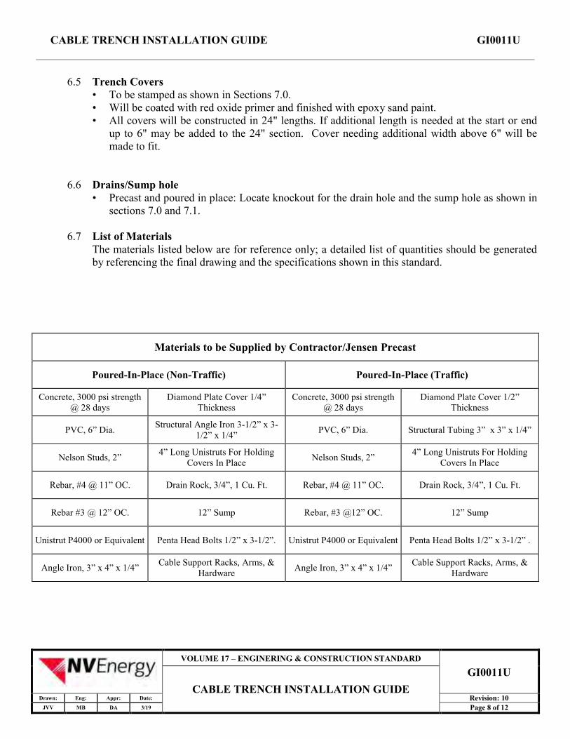
6.7 List of Materials The materials listed below are for reference only; a detailed list of quantities should be generated by referencing the final drawing and the specifications shown in this standard.
Materials to be Supplied by Contractor/Jensen Precast
Poured-In-Place (Non-Traffic) Poured-In-Place (Traffic)
Concrete, 3000 psi strength @ 28 days
Diamond Plate Cover 1/4” Thickness
Concrete, 3000 psi strength @ 28 days
Diamond Plate Cover 1/2” Thickness
PVC, 6” Dia. Structural Angle Iron 3-1/2” x 3-1/2” x 1/4”
PVC, 6” Dia. Structural Tubing 3” x 3” x 1/4”
Nelson Studs, 2” 4” Long Unistruts For Holding
Covers In Place Nelson Studs, 2” 4” Long Unistruts For Holding
Covers In Place
Rebar, #4 @ 11” OC. Drain Rock, 3/4”, 1 Cu. Ft. Rebar, #4 @ 11” OC. Drain Rock, 3/4”, 1 Cu. Ft.
Rebar #3 @ 12” OC. 12” Sump Rebar, #3 @12” OC. 12” Sump
Unistrut P4000 or Equivalent Penta Head Bolts 1/2” x 3-1/2”. Unistrut P4000 or Equivalent Penta Head Bolts 1/2” x 3-1/2” .
Angle Iron, 3” x 4” x 1/4” Cable Support Racks, Arms, &
Hardware Angle Iron, 3” x 4” x 1/4” Cable Support Racks, Arms, &
Hardware
VOLUME 17 – ENGINERING & CONSTRUCTION STANDARD
GI0011U CABLE TRENCH INSTALLATION GUIDE
Drawn: Eng: Appr: Date: Revision: 10 JVV MB DA 3/19 Page 8 of 12

CABLE TRENCH INSTALLATION GUIDE GI0011U
VOLUME 17 – ENGINERING & CONSTRUCTION STANDARD
GI0011U CABLE TRENCH INSTALLATION GUIDE
Drawn: Eng: Appr: Date: Revision: 10 JVV MB DA 3/19 Page 9 of 12

CABLE TRENCH INSTALLATION GUIDE GI0011U
7.0 PRECASTED/POURED IN PLACE TRENCH DRAWINGS 1. Contractor is to furnish and install concrete trench (Precasted is Preferred Installation). 2. Contractor to furnish and install unistruts as shown on plan view. 3. Contractor to provide NVE and/or Jensen Precast with a preliminary layout to confirm transformer
and trench layout. See section 6.8. 4. Trench walls to be formed, not cast against existing soil. 5. Concrete strength to be 3000 PSI at 28 days. Rebar yield strength shall be 60KSI. 6. Non traffic 1/4" diamond plate steel cover to be stamped "NON-TRAFFIC", "NVEO ELECTRIC"
and painted with red oxide primer and sand epoxy painted. 7. H20 traffic rated 1/2" diamond plate steel cover to be stamped "H20 TRAFFIC", "NVEO
ELECTRIC" and painted with red oxide primer and sand epoxy painted. 8. Finish exposed concrete trench edges with edging tool. 9. Backfill material shall be adjusted to ± 2% of optimum moisture content, placed and compacted in
8" lifts to 95% of maximum dry density per ASTM-0-1557. 10. Unistrut or equivalent (1-5/8"X 13/16"shall be cast into wall sections with spacing locations
(vertical/horizontal) and a length to fit wall sections as specified on NVE standard drawings. Unistrut shall be HDG unistrut P400 or equal and shall be "A" rated corrosion resistant.
11. The trench may not be extended into the building unless approved by local Inspection authority and adequate seal against water/fire is provided. (SEE NEC 300.21)
VOLUME 17 – ENGINERING & CONSTRUCTION STANDARD
GI0011U CABLE TRENCH INSTALLATION GUIDE
Drawn: Eng: Appr: Date: Revision: 10 JVV MB DA 3/19 Page 10 of 12

CABLE TRENCH INSTALLATION GUIDE GI0011U
7.1 Trench Section Details (Pedestrian / H20 Traffic Rated)
VOLUME 17 – ENGINERING & CONSTRUCTION STANDARD
GI0011U CABLE TRENCH INSTALLATION GUIDE
Drawn: Eng: Appr: Date: Revision: 10 JVV MB DA 3/19 Page 11 of 12

CABLE TRENCH INSTALLATION GUIDE GI0011U
7.2 Trench Section Details
VOLUME 17 – ENGINERING & CONSTRUCTION STANDARD
GI0011U CABLE TRENCH INSTALLATION GUIDE
Drawn: Eng: Appr: Date: Revision: 10 JVV MB DA 3/19 Page 12 of 12