broadband general network specifications - new york … · grass/sod trench installation ... aerial...
TRANSCRIPT

Broadband General Network Specifications
2|P a g e
TABLE OF CONTENTS
1. FIBER OPTIC SPECIFICATIONS .................................................................................... 1
1.1. Fiber Optic Cable Specifications .................................................................................. 1
1.2. Fiber Optic Splicing Specifications ............................................................................... 2
1.3. OTDR & Power (Insertion) Loss Testing .................................................................... 4 1.4. Fiber Acceptance Testing .............................................................................................. 4
2. INTERIOR CABLING ......................................................................................................... 6
2.1. Telecommunications Wiring Specifications ................................................................. 6
2.2. Installation Guidelines for Interior Telecommunications Cable ............................... 7
2.3. Horizontal & Riser Cabling .......................................................................................... 8
2.4. Termination, Testing & Labeling of Interior Telecommunications Cables ........... 10
2.5. Telecommunications Backbone & Riser Cables ........................................................ 11
2.6. Wireless Access Points (WAP) .................................................................................... 12 3. BONDING & GROUNDING ............................................................................................. 12
3.1. Definitions ..................................................................................................................... 12
3.2. General Bonding & Grounding Requirements ......................................................... 13
3.3. Cleaning & Treating Surfaces ..................................................................................... 14
3.4. Grounding Conductor Identification ......................................................................... 14
3.5. Routing, Supporting and Securing Grounding Conductors .................................... 15
3.6. Main Ground system .................................................................................................... 16
3.7. Equipment Chassis Ground ........................................................................................ 16
3.8. AC Electrical Conduit .................................................................................................. 16 3.9. DC Power Cabling ........................................................................................................ 16
4. CONSTRUCTION SPECIFICATIONS ........................................................................... 17
4.1. General Construction Specifications .......................................................................... 18
4.2. Underground Infrastructure Specifications .............................................................. 18
4.3. General Installation Specifications ............................................................................. 19
4.4. Direct Buried Fiber Optic Cable ................................................................................. 19

3|P a g e
4.5. Plowing .......................................................................................................................... 20
4.6. Grass/Sod Trench Installation .................................................................................... 20
4.7. Pavement Trench Installation ..................................................................................... 21
4.8. Bore Installation ........................................................................................................... 22
4.9. Rodding, Roping & Innerduct Installation ................................................................ 23 4.10. Manhole Installation ................................................................................................ 24
4.11. Handhole Installation ............................................................................................... 25
5. CABLE INSTALLATION .................................................................................................. 26
5.1. Underground Fiber Optic Cable Installation ............................................................ 26
5.2. Aerial Fiber Optic Cable Installation ......................................................................... 27
6. RIGHT-OF-WAY PROTECTION & RESTORATION ................................................. 29
7. SAFETY SPECIFICATIONS ............................................................................................ 30
8. FIRE STOPPING ................................................................................................................ 31 8.1. Fire Stopping- General ................................................................................................ 31
8.2. Cable Hole- Floor Fire Stopping ................................................................................. 32
8.3. Cable Hole- Wall Fire Stopping .................................................................................. 32
8.4. Conduits and Innerduct Fire Stopping ...................................................................... 33
9. SUBMIITALS BY CONTRACTOR .................................................................................. 33
9.1. Red-Line Drawings (As-Built Drawings) ................................................................... 37
9.2. Daily Progress Report .................................................................................................. 37
9.3. Contractor’s Construction Schedule .......................................................................... 37
1|P a g e
1. FIBER OPTIC SPECIFICATIONS 1.1. Fiber Optic Cable Specifications
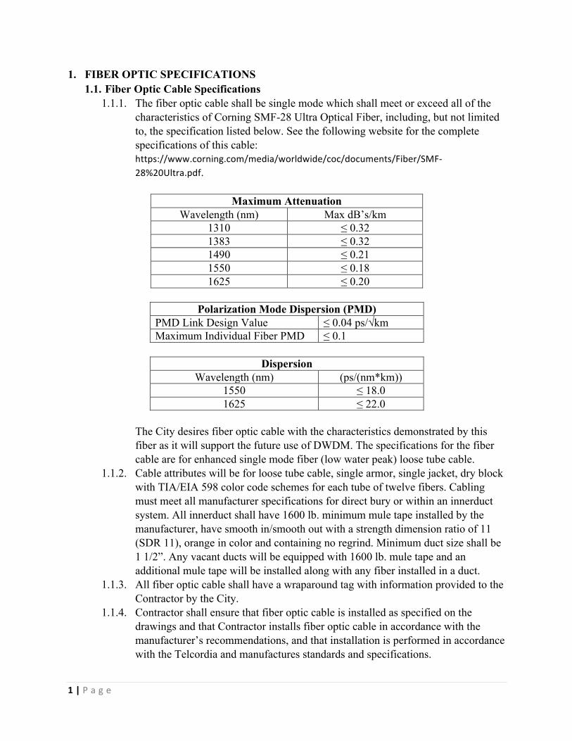
1.1.1. The fiber optic cable shall be single mode which shall meet or exceed all of the characteristics of Corning SMF-28 Ultra Optical Fiber, including, but not limited to, the specification listed below. See the following website for the complete specifications of this cable: https://www.corning.com/media/worldwide/coc/documents/Fiber/SMF-28%20Ultra.pdf.
Maximum Attenuation
Wavelength (nm) Max dB’s/km 1310 ≤ 0.32 1383 ≤ 0.32 1490 ≤ 0.21 1550 ≤ 0.18 1625 ≤ 0.20
Polarization Mode Dispersion (PMD)
PMD Link Design Value ≤ 0.04 ps/√km Maximum Individual Fiber PMD ≤ 0.1
Dispersion
Wavelength (nm) (ps/(nm*km)) 1550 ≤ 18.0 1625 ≤ 22.0
The City desires fiber optic cable with the characteristics demonstrated by this fiber as it will support the future use of DWDM. The specifications for the fiber cable are for enhanced single mode fiber (low water peak) loose tube cable.
1.1.2. Cable attributes will be for loose tube cable, single armor, single jacket, dry block with TIA/EIA 598 color code schemes for each tube of twelve fibers. Cabling must meet all manufacturer specifications for direct bury or within an innerduct system. All innerduct shall have 1600 lb. minimum mule tape installed by the manufacturer, have smooth in/smooth out with a strength dimension ratio of 11 (SDR 11), orange in color and containing no regrind. Minimum duct size shall be 1 1/2”. Any vacant ducts will be equipped with 1600 lb. mule tape and an additional mule tape will be installed along with any fiber installed in a duct.
1.1.3. All fiber optic cable shall have a wraparound tag with information provided to the Contractor by the City.
1.1.4. Contractor shall ensure that fiber optic cable is installed as specified on the drawings and that Contractor installs fiber optic cable in accordance with the manufacturer’s recommendations, and that installation is performed in accordance with the Telcordia and manufactures standards and specifications.

2|P a g e
1.1.5. Contractor shall ensure that each reel of fiber optic cable will be tested at the factory and prior to installation. Owner assumes no responsibility whatsoever for the fiber cable until final acceptance by Owner.
1.1.6. Contractor shall ensure that there shall be bonding/grounding continuity throughout the system and that all metallic sheaths shall be bonded to splice closures and/or frames and that that all splice closures and frames are bonded to a suitable earth ground. Bonds shall be accomplished using a separate bond clamp and #6 copper bond, (i.e. double framed poles).
1.1.7. Contractor shall ensure that all bonds are clean and free of debris, treated with NO-OX-ID A-Special (http://www.sanchem.com/docs/NO-OX-ID%20A-Special%20Electrical%20Grade.pdf ) and sealed within the splice closure.
1.1.8. If ground rods are required, they shall be installed to leave eight inches (8”) exposed above ground with a #6 AWG jacketed solid copper wire from the ground rod to the splice closure attached via mechanical clamps and treated with NO-OX-ID A-Special.
1.2. Fiber Optic Splicing Specifications 1.2.1. Contractor shall splice all fibers in accordance with and as designated in the splice
assignment sheets or locations, approved by City. Contractor shall splice the fiber optic cable in accordance with specifications of the manufacturer’s recommendations.
1.2.2. Contractor shall inspect all splicing equipment prior to splicing activities to ensure that the equipment is in good, clean working condition. Contractor shall calibrate the splicing equipment as recommended by the manufacturer just prior to beginning the City’s project and proof of calibration shall be given to the City prior to commencing any splicing work. City reserves the right to inspect the splicing equipment and to request the contractor to calibrate and/or clean the equipment upon inspection.
1.2.3. All fibers are to be loosed tubed, fusion spliced and organized, placed and secured in the splice closure equipment. Mass fusion splicing shall not be permitted without prior written approval by the City. Mechanical splices are not permitted. A heat oven shall be used to heat shrink all sleeves. A heat gun that is hand applied shall not be permitted. Care must be exercised to prevent damage to exposed fibers by overheating. The acrylic coating should not be removed beyond the areas that will be covered by the heat shrink sleeves.
1.2.4. Contractor should test for active/working fibers at all times. Contractor shall exercise special care and precautions. Close supervision and monitoring of this work is necessary and the provisions of this section will be adhered to. Additionally, the Contractor shall have all necessary materials to make temporary and permanent repairs to any active fibers that may be damaged during the course of the work. Contractor is solely responsible for any damages, or expenses, incurred by City due to disruptions of active/working fibers due to splicing operations.

3|P a g e
1.2.5. Terminations of the cable shall be performed in Fiber Distribution Panels (FDP) approved by the City. All terminations shall be performed in accordance with the specifications and manufacturer’s requirements.
Proper Fiber Management
Unacceptable Fiber Management Proper Fiber Management
1.2.6. Splice data shall be recorded for each attempt and shall include time of day, weather conditions including temperature and humidity, equipment used, and all other pertinent splicing information.
1.2.7. Within each splice enclosure, Contractor shall use a label maker to clearly print and identify each tray with the corresponding fibers and/or ribbons contained therein.
1.2.8. All consumables, such as electric tape, miscellaneous tie wraps, markers, etc. shall be supplied by Contractor and is considered but of the work operation.

4|P a g e
1.3. OTDR & Power (Insertion) Loss Testing 1.3.1. This work includes coordination and written notification to Owner five (5) days
prior to the start of work. Contractor shall test the fiber optic cable using an Owner approved Optical Time Domain Reflectometer (OTDR).
1.3.2. At the completion of all splice points the Contractor shall record measurements of the splice losses with an Optical Time Domain Reflectometer (OTDR). OTDR readings must be taken after the splice cases are closed and permanently racked in the hand hole/manhole in order to check for macro-bending problems. Contractor may be directed by Owner to perform temporary testing of splices. Contractor shall comply with Owner’s specifications as well as the specifications of the cable and equipment manufacturers.
1.3.3. Loss measurements shall be recorded using a laser source and a power meter. OTDR traces shall be taken and splice loss measurements recorded. The Contractor shall also store OTDR traces on diskette. Contractor shall record OTDR traces on GN Nettest or an Owner approved equivalent.
1.3.4. Contractor shall verify that all fibers have one-to-one continuity on the new cable both at the fiber level and the pigtail level. Contractor shall visually inspect fiber color and buffer tube color at each end of a span.
1.3.5. Contractor shall make three (3) attempts to achieve the allowable splice loss for each fiber.
1.3.6. Contractor shall note the fiber type and calibrate all testing and splicing equipment as applicable. This shall include but is not limited to dispersion, clad, pulse width, scan rate, and refractive index.
1.3.7. Contractor shall allow the OTDR trace sufficient time to “normalize” to avoid noisy signals on long spans.
1.3.8. All OTDR traces for final end-to-end testing will be saved to diskette and provided to Owner. When saving these OTDR traces, Contractor shall use the Owner approved format. Each diskette shall be labeled with the fiber Owner, cable type and make, the date the traces were shot, and the name of the person and company operating the OTDR.
1.3.9. When working on terminated fibers or as directed by Owner, Contractor shall test the fiber optic cable using two (2) self-contained optical power meters (OPM) which shall be capable of testing fiber optic transmission and cable facilities at 1310 nm and 1550 nm wavelengths simultaneously. Contractor shall record all power meter data and provide to Owner.
1.3.10. Contractor shall be responsible for supplying to Owner three (3) copies of OTDR software and manuals for reading OTDR traces for an IBM-compatible PC.
1.4. Fiber Acceptance Testing 1.4.1. This work includes coordination and written notification to Owner five (5) days
prior to the start of work. Contractor shall test the fiber optic cable using a GN Nettest Optical Time Domain Reflectometer (OTDR) or equivalent.
1.4.2. As splice points are completed, OTDR measurements of the splice losses will be made and recorded by the Contractor. These measurements must be made after
5|P a g e
the splice manhole or hand hole is closed in order to check for macro-bending problems.
1.4.3. After Contractor has provided end-to-end connectivity on the fibers, bi-directional end-to-end testing shall be performed. Contractor shall also perform continuity tests to verify that no fibers have been “frogged” or crossed in any of the splice points. Contractor shall immediately take action to correct any transposed or “frogged” fiber in the system. Contractor shall perform this testing and make any necessary repairs before acceptance testing is done.
1.4.4. Contractor shall submit the results from the OTDR and End-to-End Power Meter testing to Owner for review. Contractor shall submit one (1) copy of the test results in an electronic format approved by Owner, who will then review the data and identify any deficiencies. Contractor shall expeditiously repair all the deficiencies.
1.4.5. The bi-directional fiber loss calculations recorded on the End-to-End Power Meter Test Results Form (Attachment L) will be the guideline by which Owner will accept or reject the work.
1.4.6. If Contractor cannot meet the Owner’s allowable End-to-End Power Meter loss within two (2) additional splice reburn attempts, Contractor shall proceed as follows:
1.4.7. Contractor shall notify Owner of the situation and provide documentation of all three (3) splice attempts.
1.4.8. Contractor shall attempt a final splice with power optimization to obtain a splice loss not greater than 0.10 db above the allowable threshold.
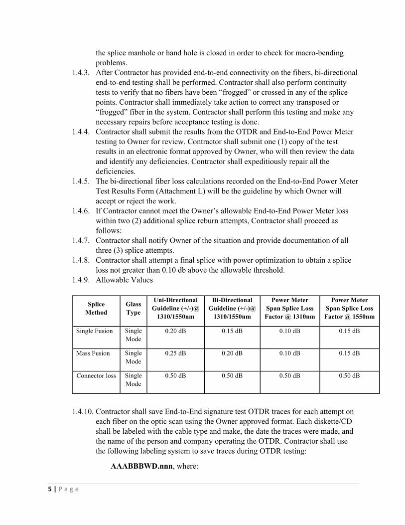
1.4.9. Allowable Values
1.4.10. Contractor shall save End-to-End signature test OTDR traces for each attempt on each fiber on the optic scan using the Owner approved format. Each diskette/CD shall be labeled with the cable type and make, the date the traces were made, and the name of the person and company operating the OTDR. Contractor shall use the following labeling system to save traces during OTDR testing:
AAABBBWD.nnn, where:
Splice Method
Glass Type
Uni-Directional Guideline (+/-)@
1310/1550nm
Bi-Directional Guideline (+/-)@
1310/1550nm
Power Meter Span Splice Loss Factor @ 1310nm
Power Meter Span Splice Loss Factor @ 1550nm
Single Fusion Single Mode
0.20 dB 0.15 dB 0.10 dB 0.15 dB
Mass Fusion Single Mode
0.25 dB 0.20 dB 0.10 dB 0.15 dB
Connector loss Single Mode
0.50 dB 0.50 dB 0.50 dB 0.50 dB
6|P a g e
AAA: Location code for the “from” site, provided by Owner
BBB: Location code for the “to” site, provided by Owner
W: The wavelength of the test (3 for 1310nm and 5 for 1550nm)
D: Direction of the testing of the fiber optic span or loop ID if direction is included in Site Code.
nnn: The fiber number being tested.
1.4.11. Loss measurements shall be recorded using a laser source and a power meter. OTDR traces shall be taken and splice loss measurements recorded. The Contractor shall also store OTDR traces on diskette. Contractor shall record OTDR traces on GN Nettest.
1.4.12. Contractor shall verify that all fibers have one-to-one continuity on the new cable both at the fiber level and the pigtail level. Contractor shall visually inspect fiber color and buffer tube color at each end of a span.
1.4.13. Contractor shall make three (3) attempts to achieve the allowable splice loss for each fiber.
1.4.14. Contractor shall note the fiber type and calibrate all testing and splicing equipment as applicable. This shall include but is not limited to dispersion, clad, pulse width, scan rate, and refractive index.
1.4.15. Contractor shall allow the OTDR trace sufficient time to “normalize” to avoid noisy signals on long spans.
1.4.16. All OTDR traces for final end-to-end testing will be saved to diskette and provided to Owner. When saving these OTDR traces, Contractor shall use the Owner approved format. Each diskette shall be labeled with the fiber Owner, cable type and make, the date the traces were shot, and the name of the person and company operating the OTDR.
1.4.17. When working on terminated fibers or as directed by Owner, Contractor shall test the fiber optic cable using two (2) self-contained optical power meters (OPM) which shall be capable of testing fiber optic transmission and cable facilities at 1310 nm and 1550 nm wavelengths simultaneously. Contractor shall record all power meter data and provide to Owner.
2. INTERIOR CABLING 2.1. Telecommunications Wiring Specifications
2.1.1. Unshielded Twisted Pair (UTP) Category 6, four pair UTP riser rated cable shall be used for horizontal wiring of buildings and plenum rated cable will be used throughout a building if cable routing is in return air spaces. All cables shall meet or exceed the following standards:
• UL 444 • UL 1666 • ANSI/TIA 568-C.2
7|P a g e
• 2011 National Electrical Code • NFPA 262 • RoHS Compliant.
2.1.2. A minimum of two UTP Category 6 cables shall be run to each station location. Each pair of station cables is considered a “jack” location. For station locations with more than two cables, additional cables shall be in pairs, with each pair being terminated and labeled as an individual “jack”, even if all are in one faceplate
2.1.3. Patch cables shall be of the same performance category, or higher, as the horizontal cables to which they connect.
2.2. Installation Guidelines for Interior Telecommunications Cable 2.2.1. The minimum horizontal cable bend radius, shall meet or exceed the
manufactures specifications, and under no-load conditions, shall be four times the diameter of the Category 6 cable. The minimum inside bend radius, under no load conditions, for 4-pair UTP patch cable shall be .25 inches.
2.2.2. The maximum tensile loading shall not exceed 25 pounds on the Category 6 cable.
2.2.3. Cable ties shall not be installed as to place a strain or compression on the cable jacket. All cable toes shall be tensioned with a cable tie tool, such as the Panduit’s GS2B Cable Tie Tool.
2.2.4. Cables that serve several adjacent rooms shall be grouped together into bundles. A single large cable bundle is preferable to several small bundles. It is preferred that the cables be grouped in a way that reduces the quantity of bundles.
2.2.5. Cables in service areas such as attics, crawl spaces, mechanical chases, and above lay-in ceilings shall be held in place with metal J-hooks or cable tray. The J-hooks shall keep cables neatly bundled and shall be located so as to reduce interference with future maintenance and construction projects. Cables shall be mounted at least 1' above drop tile ceilings, shall never lie on the ceiling, and shall always be supported every 4 feet.
2.2.6. In areas where the installation of hooks is impossible, a discussion with the City’s representative should be initiated. The cables may be bundled with plastic tie-
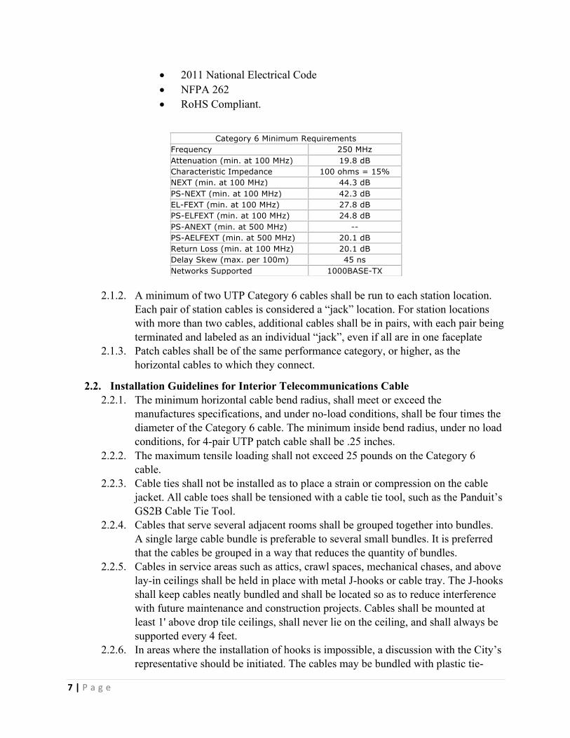
Category 6 Minimum Requirements Frequency 250 MHz Attenuation (min. at 100 MHz) 19.8 dB Characteristic Impedance 100 ohms = 15% NEXT (min. at 100 MHz) 44.3 dB PS-NEXT (min. at 100 MHz) 42.3 dB EL-FEXT (min. at 100 MHz) 27.8 dB PS-ELFEXT (min. at 100 MHz) 24.8 dB PS-ANEXT (min. at 500 MHz) -- PS-AELFEXT (min. at 500 MHz) 20.1 dB Return Loss (min. at 100 MHz) 20.1 dB Delay Skew (max. per 100m) 45 ns Networks Supported 1000BASE-TX

8|P a g e
wraps spaced no more than four feet apart, so long as the tie-wraps are tight enough to neatly bundle the cables together, but loose enough to permit the pulling of individual cables within the bundle.
2.2.7. Electrical or other tape, used for bundling cables during installation, shall be removed once the cables are in place, to allow the slack in individual cables to be more easily removed. Duct tape should never be used for this purpose.
2.2.8. A pull string must be left in conduits, cable trays and cable hooks, after initial cable installation, to allow for future cabling needs.
2.2.9. Cables that are part of a bundle shall be of uniform length. Uniform cable length is achieved by pulling on individual cables in a bundle after the bundle has been placed in the hooks or raceway and before the cables are terminated.
2.2.10. Cable bundles shall hang with minimal tension between the hooks. Check cable bundles to verify that individual cables do not have excessive tension, or are supporting the weight of several other cables.
2.2.11. At vertical to horizontal transitions, cable bundles shall have a uniform loop containing one to three feet of recoverable slack. Additional hooks may be required to support this slack.
2.2.12. Long open vertical runs shall require intermediate support. These shall support the weight of the cable between horizontal transitions. One foot of slack shall be left at each strain-relief hook so as to insure proper loading of the hooks. Vertically mounted cable tray is preferred for long vertical runs.
2.2.13. Four inches of service slack shall be left at each outlet box. 2.2.14. Twenty-four inches of recoverable slack in each cable shall be neatly bundled and
secured in the vertical wire management units located adjacent to the patch panel rack.
2.2.15. Slack or extra cable not mentioned in this section is unacceptable and shall be eliminated prior to termination.
2.2.16. Patch cables will be neatly dressed in wire managers from the patch panel insert to network switch and telephone patch panel. The upper one-half of a patch panel will have patch cables go directly up to the horizontal wire manager, then right or left to the vertical wire manager, then up or down to the network switch. The lower one-half of the patch panel will have patch cables go directly down to the horizontal wire manager, then right or left to the vertical wire manager, then up or down to the network switch.
2.3. Horizontal & Riser Cabling 2.3.1. Horizontal cabling is the portion of the telecommunications cabling system that
extends from the telecommunications room to the work area telecommunications outlet. Horizontal cabling shall be installed in a home run, star topology. It is preferred that a telecommunications room should be located on the same floor as the work areas served. The maximum horizontal distance shall be 100 meters. For ease of cable installation and future expansion in hallway or major distribution routes, cable trays are the preferred method for distributing the horizontal wiring from the telecommunications room to the communication outlets. When conduit

9|P a g e
runs are required a minimum 1” conduit shall be used. J-hooks, spaced every 4 feet, may be used for distribution of small cable bundles above suspended ceiling spaces, from major distribution routes to room outlet locations. Cable trays shall be designed to accommodate a maximum calculated fill ratio of 50% to a maximum of 6 inches inside depth, to allow for future cable installations. No cable may be attached to conduit, pipes, any other utility structure, or laid on top of ceiling tile.
2.3.2. J-hooks shall be attached to building members with fasteners appropriate for the material. Wood screws or lag bolts shall be used for wood, screws with plastic or lead anchors shall be used for plaster and concrete, self-taping screws shall be used for sheet metal. Attachment to drywall alone is not permitted.
2.3.3. Unistrut or equivalent may be used where necessary to provide attachment points for conduit or cable tray. All Thread Rod shall be secured to threaded anchors.
2.3.4. Occasionally large hooks that will carry the weight of many cables may be used, and securely attached with lag bolts, metal concrete anchors, or metal anchors with epoxy. 4.5 Hooks shall be mounted no more than four (4) feet apart. Closer spacing may be necessary in areas where cables are routed around corners or are in close proximity to other mechanical or electrical systems.
2.3.5. Where raceway, cable tray and conduit are used it shall be sized according to the list below. The minimum size for raceway and conduit is 1-inch diameter or equivalent. No more than two 90-degree bends are allowed between horizontal cable pull points, although no 90-degree bends is preferred. Use sweeping bend products when 90’s are required. The number of cables that can be installed in a conduit is limited by the allowed maximum pulling tension of the cables. A maximum fill of 40% is preferred to allow for future additions of cable.
2.3.6. Surface Raceway, Cable Tray and EMT Conduit 2.3.7. No section of interior conduit shall be longer than 100 feet between pull points.
No section of conduit shall contain more than two 90-degree bends, or equivalent between pull points. For conduits with an internal diameter of 2 inches or less, the inside radius of a bend in conduit shall be at least 6 times the internal diameter. For conduits with an internal diameter of more than 2 inches, the inside radius of a bend in conduit shall be at least 10 times the internal diameter. Conduit sizing is directly related to the planned diameter of the cable bundle, including known future installations, and the maximum pull tension that can be applied to the cable without degradation of the cable transmission properties. Conduits shall be reamed to eliminate burrs and sharp edges. Pull string or rope shall be placed in installed conduits. Flexible conduit (metal or plastic) is not permitted. Surface raceway systems shall not force cable into a bend radius less than 1.21 inches under condition of maximum fill.
2.3.8. When cables are installed in an un-insulated drywall wall, no box is required; instead a device mounting bracket can be mounted securely in the wall.
2.3.9. When a conduit and surface raceway box is used as both a jack and pull box, the minimum box depth shall be 3-1/8".

10|P a g e
2.3.10. Cable in exposed finished areas (e.g., open ceilings) shall be installed in EMT conduit, or an appropriate raceway. The preference is not to use raceway which combines electrical and communications wiring; however, power poles may be used for this when necessary.
2.4. Termination, Testing & Labeling of Interior Telecommunications Cables 2.4.1. All cables shall be terminated and tested during the installation process per
ANSI/TIA-1152 specifications, including:
• Wiremap (including shield connection, if present): Determines whether a copper twisted-pair cable is connected to the correct pin at the other end.
• Insertion Loss: Measures the signal power at the far end of the cabling as compared to the signal power at the beginning of the cabling. The result is measured in decibels (dB).
• Length: Verifies the physical length of a cable installation.
• Near-End Crosstalk (NEXT) Loss, local end and far end: Unwanted signal coupling from one pair of a cabling at the near-end onto a different pair of the cabling at the near end. NEXT is worse on wire pairs that aren’t tightly twisted.
• Power-Sum Near-End Crosstalk (PSNEXT) Loss, local end and far end: Measures NEXT in the ends of cables due to close proximity. A measurement of the unwanted signal coupling from multiple cable pairs at the near-end into a cable pair measured at the near-end.
• Attenuation to Crosstalk Ratio, Far End (ACRF): Measures signal-to-noise ratio for the cabling.
• Power Sum Attenuation for Crosstalk Ratio, Far End (PSACRF): Determines the difference in dB between the test signal and the crosstalk from the other pairs received at the far end of the link.
• Return Loss, local end and far end: Measures reflections caused by impedance changes at all locations along the link, measured in dB.
• Propagation Delay: Measures the amount of time that passes between when a signal is transmitted and when it’s received on the other end of a cabling channel.
• Delay Skew: Calculates the difference between the propagation delay for each of the four wire pairs.
2.4.2. Twisted Pairs shall not be untwisted more than 0.5 inches, and preferred .025
inches, from the point of termination for Category 6 cable. 2.4.3. The cable jacket or outer sheath shall be left intact as close to the termination as
possible. 2.4.4. Cables will be neatly dressed with tie wraps at the rear of the patch panel onto
wire managers, but not cinched so tightly as to indent the cable sheaths.
11|P a g e
Proper installation & termination of cable 2.4.5. A Category 6 cable tester shall be used to test each cable to Category 6 standards,
such as distance, attenuation; NEXT, crosstalk, opens, shorts, pair polarity and connector pin-out.
2.4.6. Test results will be saved on the tester and then downloaded to a format that is acceptable to the City. Any cables not passing all tests shall be investigated, the cause(s) resolved, and the cable re-tested, until all tests are passed for warranty submission. Final test results must be provided to the City in an acceptable format.
2.4.7. As-built drawings shall be provided and at minimum shall show cable routes, telecommunication room and outlet locations. CADD or Visio drawings will be given to the City.
2.4.8. Each outlet and patch panel pair of ports shall be clearly labeled in both the telecommunications room and the workstation location with the workstation room number. If there are multiple jacks in a room, the numbering shall include a hyphen suffix designation, such as 232-1, 232-2, and will begin at the closest jack to the left of the main doorway (standing in the doorway, looking in), and proceed clockwise around the room. Single jacks in a room shall be labeled with just the room number and will not have a hyphen suffix designation (e.g., 233, 234). If there are jacks located in the center of the room, after going around the exterior of the room, go up the middle from the main doorway. The label at the outlet will be placed on either the top of the faceplate (if difficult to see the front of the faceplate), or on the top label indentation on the front of the faceplate. Four-plex or greater density jack plates will be labeled as two (or more) jacks rather than one, such as 101-1, 101-2. Each jack consists of 2 cables.
2.5. Telecommunications Backbone & Riser Cables 2.5.1. Copper Cables shall be a CMR rated ARRM-type shielded riser cable, with a fire
retardant PVC jacket. If this feed is routed, in whole or in part, in underground conduit, the use of an Alpeth shielded air core PIC-type cable is preferred
2.5.2. Intra-Building Feed – Backbone telephone cable from the building Entrance Protector location to the telecommunications room(s), if they are in different locations, shall be CMR rated ARRM-type shielded riser cable, and will be installed in conduit unless cable hooks or cable tray are used, and will be concealed from public spaces.
2.5.3. Indoor riser rated fiber optic cable will be used and installed in conduit, cable tray, or in innerduct in cable hooks in concealed spaces. A determination will be made as to whether multi-mode or single-mode fiber optic cable, or both, will be used. Fiber optic cable will be terminated and tested before the fiber is put into use. Fiber test results shall be provided to the Owner. Riser cable connections will be made to the fiber optic building entrance location equipment, and in the telecommunications room active rack.
12|P a g e
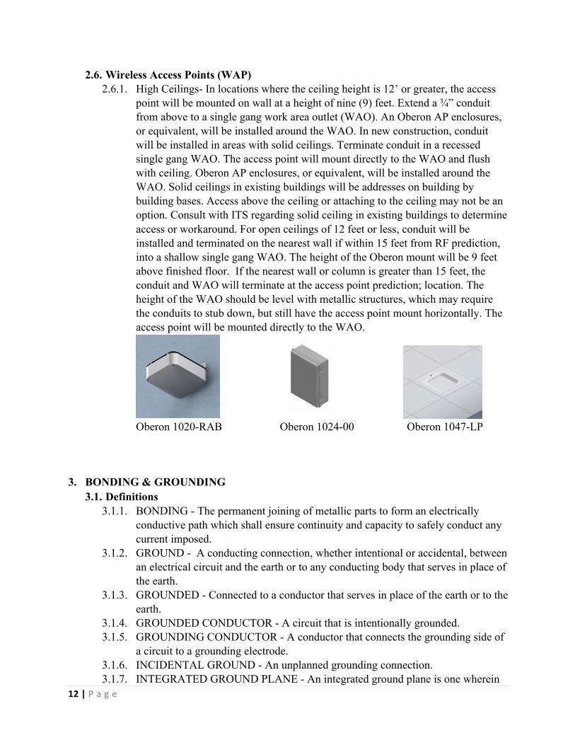
2.6. Wireless Access Points (WAP) 2.6.1. High Ceilings- In locations where the ceiling height is 12’ or greater, the access
point will be mounted on wall at a height of nine (9) feet. Extend a ¾” conduit from above to a single gang work area outlet (WAO). An Oberon AP enclosures, or equivalent, will be installed around the WAO. In new construction, conduit will be installed in areas with solid ceilings. Terminate conduit in a recessed single gang WAO. The access point will mount directly to the WAO and flush with ceiling. Oberon AP enclosures, or equivalent, will be installed around the WAO. Solid ceilings in existing buildings will be addresses on building by building bases. Access above the ceiling or attaching to the ceiling may not be an option. Consult with ITS regarding solid ceiling in existing buildings to determine access or workaround. For open ceilings of 12 feet or less, conduit will be installed and terminated on the nearest wall if within 15 feet from RF prediction, into a shallow single gang WAO. The height of the Oberon mount will be 9 feet above finished floor. If the nearest wall or column is greater than 15 feet, the conduit and WAO will terminate at the access point prediction; location. The height of the WAO should be level with metallic structures, which may require the conduits to stub down, but still have the access point mount horizontally. The access point will be mounted directly to the WAO.
Oberon 1020-RAB Oberon 1024-00 Oberon 1047-LP
3. BONDING & GROUNDING 3.1. Definitions
3.1.1. BONDING - The permanent joining of metallic parts to form an electrically conductive path which shall ensure continuity and capacity to safely conduct any current imposed.
3.1.2. GROUND - A conducting connection, whether intentional or accidental, between an electrical circuit and the earth or to any conducting body that serves in place of the earth.
3.1.3. GROUNDED - Connected to a conductor that serves in place of the earth or to the earth.
3.1.4. GROUNDED CONDUCTOR - A circuit that is intentionally grounded. 3.1.5. GROUNDING CONDUCTOR - A conductor that connects the grounding side of
a circuit to a grounding electrode. 3.1.6. INCIDENTAL GROUND - An unplanned grounding connection. 3.1.7. INTEGRATED GROUND PLANE - An integrated ground plane is one wherein
13|P a g e
the communications system circuit ground points and the DC conductors are not deliberately isolated from framework, and/or the framework is not deliberately isolated from contact via the building steel or other incidental conductive paths to foreign communications system ground planes or to the earth.
3.1.8. ISOLATED GROUND PLANE - An isolated ground plane is one where the communications system circuit ground points and DC return conductors are deliberately isolated from framework that is part of an integrated ground plane. All objects that comprise this isolated ground plane are insulated from contact with other ground planes, except for a single point connection that functions to equalize potential difference between the otherwise unconnected planes.
3.1.9. GROUND WINDOW - A spherical zone extending to a radius of 3 feet from the midpoint of the main ground bus. If a ground window is located at a power plant return bus bar a point on the bus bar should be selected for the center point of the imaginary sphere.
3.1.10. C.O. GROUND - A system of conductors used to provide a low impedance path to the office principle ground point (OPGP).
3.1.11. OFFICE PRINCIPLE GROUP - A conducting interface for various grounding conductors in a building and the ground electrode system.
3.2. General Bonding & Grounding Requirements 3.2.1. To ensure the safety of the Contractor’s employees and equipment protection, all
relay racks, cabinets, framework, metallic battery stands, rectifiers, generators, commercial or emergency power devices, etc. shall be grounded. The Ground Source must comply with the following:
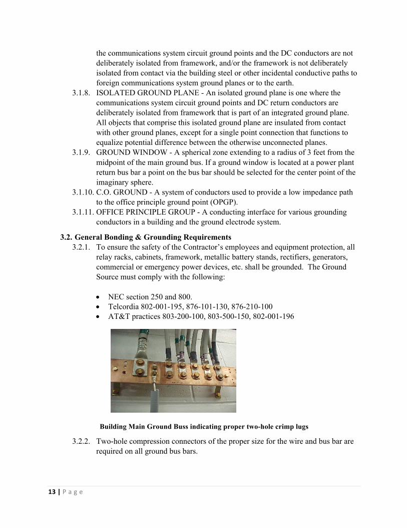
• NEC section 250 and 800. • Telcordia 802-001-195, 876-101-130, 876-210-100 • AT&T practices 803-200-100, 803-500-150, 802-001-196
Building Main Ground Buss indicating proper two-hole crimp lugs
3.2.2. Two-hole compression connectors of the proper size for the wire and bus bar are required on all ground bus bars.
14|P a g e
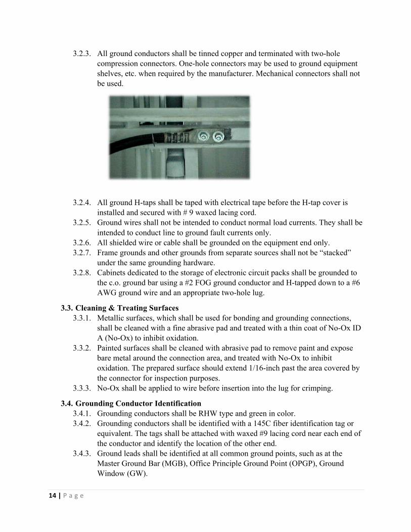
3.2.3. All ground conductors shall be tinned copper and terminated with two-hole compression connectors. One-hole connectors may be used to ground equipment shelves, etc. when required by the manufacturer. Mechanical connectors shall not be used.
3.2.4. All ground H-taps shall be taped with electrical tape before the H-tap cover is installed and secured with # 9 waxed lacing cord.
3.2.5. Ground wires shall not be intended to conduct normal load currents. They shall be intended to conduct line to ground fault currents only.
3.2.6. All shielded wire or cable shall be grounded on the equipment end only. 3.2.7. Frame grounds and other grounds from separate sources shall not be “stacked”
under the same grounding hardware. 3.2.8. Cabinets dedicated to the storage of electronic circuit packs shall be grounded to
the c.o. ground bar using a #2 FOG ground conductor and H-tapped down to a #6 AWG ground wire and an appropriate two-hole lug.
3.3. Cleaning & Treating Surfaces 3.3.1. Metallic surfaces, which shall be used for bonding and grounding connections,
shall be cleaned with a fine abrasive pad and treated with a thin coat of No-Ox ID A (No-Ox) to inhibit oxidation.
3.3.2. Painted surfaces shall be cleaned with abrasive pad to remove paint and expose bare metal around the connection area, and treated with No-Ox to inhibit oxidation. The prepared surface should extend 1/16-inch past the area covered by the connector for inspection purposes.
3.3.3. No-Ox shall be applied to wire before insertion into the lug for crimping.
3.4. Grounding Conductor Identification 3.4.1. Grounding conductors shall be RHW type and green in color. 3.4.2. Grounding conductors shall be identified with a 145C fiber identification tag or
equivalent. The tags shall be attached with waxed #9 lacing cord near each end of the conductor and identify the location of the other end.
3.4.3. Ground leads shall be identified at all common ground points, such as at the Master Ground Bar (MGB), Office Principle Ground Point (OPGP), Ground Window (GW).

15|P a g e
3.4.4. Ground leads shall be identified when terminating on a bus bar of any power plant, Battery Distribution Fuse Bay (BDFB), etc.
3.4.5. A brass “Do Not Disconnect” tag shall be attached to each end of the following types of ground conductors:
• Vertical risers and horizontal equalizers • All grounding electrode conductors • All grounding conductors extending between the Central Office Ground Bar
and the Office Principal Ground Point Bus 3.5. Routing, Supporting and Securing Grounding Conductors
3.5.1. Grounding conductors shall not be run on cable racks with power or switchboard cable, and shall be run so that they can be inspected. Horizontal runs shall be supported using cable support brackets hanging below the cable rack, turned inward.
3.5.2. Grounding conductors shall be supported on 6-inch “L” brackets and secured at intervals of no more than eighteen (18) inches.
3.5.3. Grounding conductors shall be secured to support brackets with #9 waxed lacing cord to maintain a neat appearance and to prevent the conductors from falling off the support brackets. All excess lacing cord shall be trimmed not to exceed ½-inch in length.
3.5.4. Grounding conductors shall take the most direct and straight path possible without any sudden changes in direction.
3.5.5. Grounding conductors shall have a minimum bending radius of one (1) foot, and should have as large a radius as possible.
3.5.6. The direction of bend in a grounding conductor shall point towards the OPGP. 3.5.7. The Contractor’s Engineer, Consulting Engineer if utilized, and Installer shall
review the grounding system to ensure proper installation. 3.5.8. To prevent a choke coil effect (girdling), the following guidelines should be
observed: 3.5.9. At locations where a vertical riser passes through walls and floors, nonmetallic
sleeves are required. 3.5.10. Fully closed metallic rings shall not be used to support grounding conductors. 3.5.11. Grounding conductors shall not be run inside of metal conduit or be secured by
metallic clamps that encircle the conductor. 3.5.12. Minimum conductor size for relay racks, cabinets and framework is #6 AWG.
“Daisy chaining” of equipment grounds is not permitted.

16|P a g e
Bonding Relay Racks
3.5.13. Ground cables leaving ladder racking shall not be unsupported for a distance greater than 2 foot-0 inch for sizes 1/0 AWG and smaller, and 3 foot-0 inch for 2/0 AWG and larger.
3.5.14. 180-degree bends in grounding conductors are not allowed. When attaching to the frames a “lazy S” shall be employed. Ground conductors shall bend in the direction of the main ground.
3.6. Main Ground system 3.6.1. The vertical ground riser shall be continuous and free of sharp bends. 3.6.2. PVC or other nonmetallic sleeve is required for routing the vertical ground riser
through floors. If local code requires a metallic sleeve, it shall be less than three feet long, and both ends of the sleeve shall be bonded to the vertical riser using #6 AWG stranded copper wire. The use of non-sleeved holes is not permitted.
3.6.3. PVC sleeves shall extend four inches above and two inches below the floor and be adequately fire stopped.
3.7. Equipment Chassis Ground 3.7.1. If a manufacturer provides a chassis ground termination point, that bond shall be
made per manufacturer’s specification.
3.8. AC Electrical Conduit 3.8.1. All conduits shall be installed in accordance with specifications and drawings. 3.8.2. All unused knockouts of boxes and cabinets shall be closed. 3.8.3. Conduits shall be placed so as not to block future cabling, etc. 3.8.4. All conduits shall be appropriately grounded according to the requirements of the
system that it supplies. 3.8.5. The allowable number and gauge of wires in a conduit shall be in accordance with
the requirements of the National Electric Code (NEC). 3.8.6. Conduit shall be supported every 5 feet to a maximum of 6 feet.
3.9. DC Power Cabling 3.9.1. Locations Requiring Protection

17|P a g e
3.9.1.1. Wire and cable turning off of cable racks shall be protected by fiber paper or U-shaped fiber insulators. The insulators or paper shall be secured in place with #9 lacing cord.
3.9.1.2. Power wire or cable shall be protected with fiber paper where it passes through or comes in contact with edges of sheet metal openings or around any sharp edges of framework, racking, etc.
3.9.1.3. The Installer shall protect existing equipment and cable from damage during all power cabling activities.
3.9.1.4. Cable rack hanger rods shall have fiber or polyvinyl tubes placed over them where cable rack is supported by threaded rod.
3.9.2. Power Cables and Wires 3.9.2.1. Power cables shall be run and secured on cable racks dedicated to power
cables. 3.9.2.2. Power cabling shall not be run adjacent to transmission cabling. 3.9.2.3. Grounding leads are not battery return leads, and shall not be run on the
cable rack with power cable. Grounding leads will be installed on 6-inch “L” brackets hung from A-deck.
3.9.2.4. AC and DC power cabling shall not be run on the same cable rack. 3.9.2.5. Exposed ends of power cable shall be insulated with tape and heat shrink
caps. 3.9.2.6. Cable must flow over the edge of the cable rack, not through the cable rack. 3.9.2.7. Un-fused power cables must be installed on a dedicated power rack. Cable
rack must be labeled as un-fused power cables. 3.9.3. Securing Power Cable
3.9.3.1. Power cables that leave cable racks and enter frames, racks, and other equipment shall not be unsupported for a distance greater than two (2) feet for cables 1/0 and smaller. Cables 2/0 and larger shall not be unsupported for a distance greater than three (3) feet.
3.9.3.2. Power cables shall be secured using #9 waxed lacing cord and the appropriate stitching and knots.
3.9.4. Labeling 3.9.4.1. All battery strings and cells shall be labeled by number starting with cell #1
at the positive post. 3.9.4.2. Chargers, rectifier cabinets and Power Distribution Bays shall be labeled on
the top center, both front and rear, with black ½-inch high letters in accordance with the project plans.
3.9.4.3. All distribution circuits shall be labeled, including fuse blocks, fuse panels, and circuit breakers. Circuit breakers and fuses will be labeled from the top down and will be labeled in sequential order.
4. CONSTRUCTION SPECIFICATIONS
18|P a g e
4.1. General Construction Specifications 4.1.1. Workmanship shall be professional in nature and any necessary installations shall
be done in accordance with accepted commercial standards and codes. All materials and equipment shall be applied, installed, connected, erected, utilized, cleaned and conditioned in accordance with the instructions of the applicable manufacturer, fabricator or processor, except as otherwise provided in the Contract Documents.
4.1.2. The Contractor is responsible for applying fire-stopping material in and around any openings (e.g., at a building entry point) that it creates or are created for it where code or good engineering practice suggests or requires the use of fire stopping material. The Contractor shall ensure that all fire-stopping materials meet appropriate codes and are applied according to good engineering practice.
4.1.3. The Contractor is responsible for creating a waterproof seal in and around any openings to the outside environment that it creates or are created for it. The Contractor shall ensure that all waterproof materials meet appropriate codes and are applied according to good engineering practice.
4.1.4. The Contractor shall at all times comply with the National Electrical code; the National Electrical Safety Code as prepared by the Institute of Electrical and Electronics Engineers; the National Electrical Code of the National Fire Protection Association; and other applicable federal, state and local law provisions.
4.1.5. The Contractor shall at all times comply with all State and Federal laws as they relate to employee safety, i.e., AHERA, OSHA, Confined Space Entry, Employee Right to Know, Respiratory Protection, NESHAP, Lock Out Tag Out, etc.
4.1.6. If the Contractor observes—during preliminary examinations or subsequent work— existing violations of fire stopping, electrical wiring, grounding, or other safety- or code related issues, the Contractor shall report these to Owner in a timely manner.
4.1.7. All conduits and cable shall be plugged or capped during the construction process and upon completion to prevent any intrusion of silt, water, or foreign substances into the Network. Contractor shall abide by the following acceptable practices to complete the installation:
4.2. Underground Infrastructure Specifications 4.2.1. Clear Right-Of-Way (Row)
4.2.1.1. This work includes coordination and written approval with Owner prior to the start of work. All trees and/or brush shall be cut so that stumps protrude from the ground at a height no greater than two inches (2”). Clearing by Contractor shall be complete with the removal or chipping of the cleared material and is considered part of the work operation.
4.2.1.2. All trimming and pruning shall be done by cutting only. No stripping, peeling, or breaking of limbs shall be allowed. When trimming shrubs and trees, Contractor shall use sharp, disease-free tools. All cuts shall be clean, and no stubs greater than one-quarter inch (1/4”) shall be allowed. Exposed

19|P a g e
bark or limbs shall not be painted or treated in any way. Clearing and trimming shall be complete with the removal or chipping of cleared material and is considered part of the work operation.
4.2.1.3. Contractor shall remove existing fences on the right-of-way only upon written approval. Contractor shall remove temporary fencing erected by Contractor as soon as practicable.
4.2.1.4. Contractor shall abide by any and all applicable rules and regulations concerning clearing the right-of-way. Any penalties and/or fines for violations incurred during the clearing of the right-of-way shall be the sole responsibility of Contractor.
4.2.1.5. Contractor shall verify all restoration or replacement requirements in connection with clearing activities with the ROW Owner. Contractor shall solely be responsible for abiding by the requirements set forth by ROW Owner.
4.3. General Installation Specifications 4.3.1. Warning tape shall be installed twelve inches (12”) below existing grade and is
considered part of the work operation. 4.3.2. If a dielectric cable is used, Contractor shall install a 14 gauge insulated locate
wire within all trench line excavations leading into access points, and is considered part of the work operation. Locate wire shall be installed using industry standards, or, as described and as shown on the typical details. Where a metallic sheath is present in the cable a locate wire is still necessary.
4.3.3. In applications where HDPE ducts are installed, Contractor shall install the ducts to prevent excessive waving of the ducts within the trench. Contractor shall tension the ducts to prevent waving in the trench prior to backfilling. Conduits shall be installed in such a manner as to keep conduit configuration consistent. Conduits shall be bound along the trench line every ten feet (10’) to maintain this configuration and minimize spiraling.
4.3.4. Trenches shall be kept as straight as practical. The bottom of the trench shall be smooth and free from any sharp edges. The trench shall be kept clear of debris and loose rock. All changes in trench grade shall be less than one foot (1’) per ten feet (10’).
4.3.5. The Contractor’s Project Manager or his/her designee shall carefully inspect cable during and prior to installation to be certain that it is free from defects or damage.
4.4. Direct Buried Fiber Optic Cable 4.4.1. The Contractor’s Project Manager or his/her designee shall carefully inspect cable
during and prior to installation to be certain that it is free from defects or damage. 4.4.2. Bends of small radii and twists that might damage cable shall be avoided. During
the installation, cable shall not be bent in a radius less than twenty (20) times the outside diameter of the cable or as specified by the cable manufacturer.
4.4.3. Care is to be exercised during the plowing operation, to insure that the cable is fed either manually or by capstan into the ground through the plow loose and without tension.

20|P a g e
4.4.4. All open cable ends, either placed or remaining on a cable reel, shall have a cable cap placed on them.
4.5. Plowing 4.5.1. Plowing innerduct includes the hauling of inner duct from storage area to work
location and any handling required to properly install (via direct burying) the innerduct in the ground to a minimum 36” cover, or in accordance with jurisdictional authorities. This includes coordination with utility Owners in locating their facilities prior to the installation of the innerduct.
4.5.2. The plowing equipment shall be subject to the approval of the jurisdictional authorities having jurisdiction over roadway and railroad ROW.
4.5.3. The equipment and construction methods used by the Contractor shall be such as to cause minimum displacement of the soil. The slot made in the soil by the cable plows shall be closed immediately by driving a vehicle track or wheel over the slot or by other suitable means.
4.5.4. Damage to banks, ditches, and roads caused by the equipment shall be immediately repaired and restored to original condition to the satisfaction of the jurisdictional authorities.
4.5.5. The Contractor shall promptly repair any damage to fences, lawns, shrubbery, drives and any other property damaged during construction to original condition.
4.5.6. After installation, the fiber optic cable shall be tested for sheath faults to ground by the Contractor.
4.5.7. The start pits, finish pits, and pits at points of intersections will be excavated in advance of plowing. Utility crossings will be exposed prior to start of plowing operations. The Contractor will exercise care in the use of trenching equipment and shovels in joining slots and/or trenches to other slots/trenches to be certain that the cable is not damaged.
4.6. Grass/Sod Trench Installation 4.6.1. Contractor shall excavate as required (i.e. machine trench, backhoe, hand dig,
etc.) to install ducts as indicated in the Contract Drawings and typicals to allow a minimum of thirty-six inches (36”) of cover to top of conduit below finished grade, or as specified on the Contract Drawings and/or permits. The installation shall be complete with removal and disposal of excavated materials or materials not suitable for backfill and the installation of the conduit.
4.6.2. Restoration shall include the placement of select fill or clean backfill properly compacted. Clean backfill is defined as existing native soil containing material that is free of debris. Restoration may also include shoring, bracing, road bore connections, and all other operations necessary to complete the installation.
4.6.3. Contractor shall be responsible to ensure tie-ins and duct couplings are made to ensure elevations remain as straight as possible and that the duct and conduit joints provide an airtight seal. Contractor shall furnish duct couplers to achieve this requirement.

21|P a g e
4.6.4. All trench sections must be closed at the end of each working day. Contractor shall restore the surface conditions to original or better conditions or as required by the jurisdictional authorities.
4.6.5. Contractor shall notify Owner of areas where minimum cover requirements cannot be met. Contractor shall ensure that locations with minimum cover are protected by such means as to cover conduit with ¼” steel plates, concrete slurry, or both. This material and installation cost shall be borne by Contractor.
4.7. Pavement Trench Installation 4.7.1. Contractor shall excavate as necessary to install ducts as specified on the
construction typicals or as specified on the Contract Drawings and typicals. The installation shall be completed by saw cutting the roadway surfaces, removing and disposing of excavated pavement and excess excavated material and installing the conduit.
4.7.2. Restoration shall include the placement of select fill or clean backfill compacted in eight-inch (8”) lifts. Clean backfill is defined as existing native soil containing material that is free of debris and contains no cobbles. Restoration may also include shoring, bracing, road bore connections, and all other operations necessary to complete the installation.
4.7.3. Temporary pavement restoration shall be required when vehicular traffic shall be present prior to final pavement restoration. The jurisdictional authorities shall govern final pavement restoration. Final asphalt restoration shall typically include roto-milling to remove existing asphalt six inches (6”) on each side of the trench. Final concrete restoration shall typically include replacing the concrete to match the existing roadway cross-section.
4.7.4. Contractor shall be responsible to ensure tie-ins and duct couplings are made to ensure elevations remain straight as possible and that the duct and conduit joints provide an airtight seal. Contractor shall furnish duct couplers to achieve this requirement.
4.7.5. Driveways, lanes, or roadways when required to be open cut, shall be opened just prior to the conduit placing. In no case shall the driveway, lane, or roadway be left impassable at the end of each workday. The general public safety is paramount and appropriate steps shall be taken to ensure safety at all times. Where a drive or roadway must be left open for traffic, Contractor must provide the material and method required to allow for movement of traffic.
4.7.6. Trenches shall be promptly backfilled with select material and placed so that final grade is restored to original grade to ensure no hazard to vehicular, animal or pedestrian traffic. No trenches shall be left open overnight. Upon approval all open trenches shall be properly guarded or barricaded to prevent damage or injury.
4.7.7. In areas inaccessible to tamping type rollers where compaction is required, a mechanical tamper of a size suitable for the work involved shall be used. Pneumatic tampers shall be operated at pressures no less than those recommended by the manufacturer.
22|P a g e
4.7.8. Contractor shall notify Owner of areas where minimum cover requirements cannot be met. Contractor shall ensure that locations with minimum cover are protected by such means as to cover conduit with ¼” steel plates, concrete slurry, or both. This material and installation cost shall be borne by Contractor.
4.8. Bore Installation 4.8.1. Boring shall be completed with the excavation of bore launching and receiving
pits, any required shoring, any required rock removal, and the installation of the conduit at a depth no less than thirty-six inches (36”) of cover. Maximum depth of bore installation shall not exceed eight feet (8’). Bore installation shall include pushing, boring, or simultaneously boring and pushing casing pipes and duct under roads, exit ramps, railroad tracks, driveways, sidewalks, trees, environmentally sensitive areas and other features indicated on the Contract Drawings or as directed by jurisdictional authorities. Acceptable methods of boring include jack boring, dry auger boring, and directional boring.
4.8.2. Duct shall be installed in locations as shown on the Contract Drawings. Contractor shall plan all bores as to not exceed fifteen degrees (15°) of bends in the duct. Bore pits shall be placed to conform to regulations mandated by the jurisdictional authorities as necessary.
4.8.3. Before boring, Contractor shall check all obstructions and clearances. All existing utilities and facilities shall be located and remain open until the bore has been completed.
4.8.4. No bore pits or potholes shall be left open overnight. Upon approval, all open bore pits or potholes shall be properly guarded or barricaded to prevent damage or injury.
4.8.5. Contractors’ bore operator and navigator shall maintain communication at all times. When visual obstruction or distance precludes un-aided verbal communication, the operator and navigator shall utilize radio communication devices. An additional third person that has a clear view of the entire operation shall be used, wherever practical without creating an additional safety hazard.
4.8.6. The boring operator shall have full control of the direction of the boring tool at all times. Shallow, misdirected, unsuccessful bores and voids shall be abandoned and completely at Contractor’s expense. Under no circumstances shall the Contractor be allowed to cut or disturb pavement or asphalt, or excavate within the relative limits of any roadway surface to retrieve any lost boring apparatus.
4.8.7. All ends of bore casing shall be sealed using non-shrink grout. All conduits shall be capped, sealed watertight and shall be well marked to accommodate locating. All bore pits shall be dewatered.
4.8.8. Restoration shall include the placement of select fill or clean backfill compacted in eight-inch (8”) lifts. Clean backfill is defined as existing native soil containing material that is free of debris and contains no cobbles. Restoration may also include shoring, bracing, road bore connections, and all other operations necessary to complete the installation. Surfaces shall be restored to original or better condition or as mandated by the jurisdictional authorities.
23|P a g e
4.8.9. Contractor is to use proper dewatering and containment methods for removal and disposal of bore water and any and all additives for wall stabilization.
4.8.10. Setup of directional boring equipment must be made in a manner to minimize damage to the surrounding area. Emphasis shall be placed on setup locations to ensure that the equipment, debris, and/or bore water overflow do not encroach onto private property or public drainage systems. Contractor shall be responsible for disposing of all waste.
4.8.11. All directional boring equipment shall have electrical protective devices to protect the operators from electrical shock. Contractor requires that these devices not be circumvented in any way and that all protective safety equipment is worn or used by all required individuals. Anyone not wearing or using protective equipment shall not approach or touch the directional drilling equipment.
4.8.12. No items attached to the backside of the reamer shall be allowed without the use of a free-moving swivel to eliminate the rotation of trailing stem. When adding additional stem or attachments where the addition/attachment is not within sight of the bore machine operator, all power providing any movement to stems shall be disengaged and the stems at the boring rig shall be locked down. Power shall only be reinstated after the item being attached to the stem is securely connected and all personnel are clear of moving components.
4.8.13. Contractor shall be responsible ensure tie-ins and duct couplings are made to ensure elevations remain straight as possible and that the duct and conduit couplers provide an airtight seal.
4.8.14. Contractor shall in his pre-bid survey determine soil conditions. Rock conditions shall be determined by Contractor prior to project commencement, and will not be considered for a request for change order. It is the responsibility of the Contractor to familiarize themselves with the ground conditions. Geo-Tech or similar reports will not be provided for the area.
4.8.15. Contractor shall notify Contractor of areas where minimum cover requirements cannot be met. Contractor shall ensure that locations with minimum cover are protected by such means as to cover conduit with ¼” steel plates, concrete slurry, or both. This material and installation cost shall be borne by Contractor.
4.9. Rodding, Roping & Innerduct Installation 4.9.1. Contractor shall determine the integrity of existing sections of conduit prior to
installation of any pull line. 4.9.2. Contractor shall use a variable length rodder to physically “rod” the existing
innerduct. This activity will determine whether or not the conduit run is continuous or whether collapsed or damaged conduits exist. Should a damaged conduit be found, Contractor shall notify the Owner within forty-eight (48) hours.
4.9.3. Once a determination has been made that the conduit run is successful, Contractor shall “rope” the existing conduit run with a pull line or mule tape.
4.9.4. Proofed and/or verified conduits shall have innerducts placed within them as directed by Owner. Contractor shall use swivels any time innerduct is being installed to prevent twisting of the duct.
24|P a g e
4.9.5. Contractor shall apply lubricant, at Contractor’s expense, as required during the innerduct installation process.
4.9.6. Contractor shall provide enough manpower to sufficiently manage and supervise all installations.
4.9.7. Contractor shall ensure breakaway tension of the winch is within the specifications of the innerduct manufacturer.
4.9.8. Each innerduct shall have a pull line or other pull rope installed. 4.9.9. Contractor shall furnish and install a blank duct plug to each innerduct, making
sure to tie-off all pull lines. 4.9.10. Contractor shall use caution through the entire rodding, roping and innerduct
installation process to avoid damaging any existing conduits, innerducts, cables, or other previously existing plant.
4.9.11. Contractor shall prepare, and furnish to Owner, butterfly drawings of manhole system showing Owner duct and overall layout of ducts in the manhole.
4.10. Manhole Installation 4.10.1. The Contractor shall install manholes at locations as shown on the Contract
Drawings and as approved by Contractor. The Contractor shall install manholes to the specifications as depicted on the typical drawings and any applicable jurisdictional authorities’ specifications.
4.10.2. Contractor shall place the manholes on a minimum eight-inch (8”) thick bed. Bed material shall consist of clean three quarter inch (3/4”) crushed stone placed on filter fabric. For open bottom manholes, Contractor shall place a rodent-proof mesh on top of the gravel bedding. The ducts shall enter and leave manholes exactly opposite each other. Frames and covers shall be installed to match existing grade unless otherwise noted and shall be shimmed with either steel or concrete spacers.
4.10.3. Contractor shall not use material less than five thousand pounds per square inch (5,000 psi) in density to shim frames and covers or as necessary to maintain the load rating on the manholes.
4.10.4. The manholes shall not be installed on steep banks or slopes where the cover cannot be leveled within a tolerance of one-inch (1”) of drop to twelve inches (12”) of grade.
4.10.5. All manhole penetrations shall be sealed with a non-shrink grout. All conduit and duct ends shall be sealed with Contractor supplied duct plugs/caps. Large diameter ducts shall be trimmed neatly inside the manhole. For PVC conduit installation’, conduits shall be flush to the interior manhole wall. During installation of HDPE conduits, conduits shall extend 12” into the manhole.
4.10.6. Contractor shall also ensure that the manholes have the following: 4.10.7. Bonding inserts and struts for racking. 4.10.8. Pulling eyes at least 22 mm (7/ 8 in) in diameter. 4.10.9. A sump drywell of at least 200 mm (8 in) in diameter. 4.10.10. An entry ladder (required). 4.10.11. Appropriate grounding points including two (2) ½ inch copper clad ground rod.

25|P a g e
4.11. Handhole Installation 4.11.1. Contractor shall install hand holes at locations as shown on the drawings and as
approved by Owner. The Contractor shall install hand holes to the specifications as depicted on the typical drawings and any applicable jurisdictional authorities’ specifications.
4.11.2. Contractor shall place the hand holes as per the typical drawings. Contractor shall place a rodent-proof mesh on top of the gravel bedding. The ducts shall enter and leave hand holes exactly opposite each other.
4.11.3. Hand holes shall be placed so that the top sits flush with the existing grade unless otherwise noted.
4.11.4. The hand holes shall not be installed on steep banks or slopes where the cover cannot be leveled within a tolerance of one-inch (1”) of drop to twelve inches (12”) of grade.
4.11.5. All conduit and duct ends shall be sealed with Contractor supplied duct plugs/caps. Large diameter ducts shall be trimmed neatly inside the manhole. For PVC conduit installation, conduits shall be flush to the interior manhole wall. During installation of HDPE conduits, conduits shall extend 12” into the manhole.
4.11.6. Contractor shall install a ½ inch copper clad ground rod in all manholes. 4.11.7. All hand hole lids should be a minimum of ANSI/SCTE 77 2007, Tier 22 for
“Driveway, parking lot, and off roadway applications subject to occasional non-deliberate heavy vehicular traffic’ and AASHTO H-20 Certified precast concrete, cast iron or other AASHTO recognized materials for “Deliberate vehicular traffic applications” Please note, that there are currently no AASHTO design or test provisions for polymer composites.
4.12. Route Markers 4.12.1. Contractor shall install cable route warning signs along the route to allow for
route protection and maintenance. Contractor shall exercise special caution to locate the cable route markers and cable location signs to avoid interference with the warning tape, conduit, and any other existing facilities. Placement of route markers is considered part of the cable placement work operation.
4.13. Coring 4.13.1. Contractor shall perform all cores into abutments, tunnel walls, manholes, hand
holes, and vaults by utilizing a core drill with a core type bit. Contractor shall drill a pilot hole prior to performing the core to verify the core’s location. Contractor shall core a hole that is not more than one half inch (1/2”) greater than the outside diameter of the conduit that is being placed through the core. Contractor shall seal the core utilizing a non-shrink grout.
4.13.2. Contractor shall adhere to the specifications imposed by the Owner of the facility being cored into.
4.13.3. Contractor shall perform all cores into buildings by utilizing a core drill with a core type bit. Contractor shall drill a pilot hole prior to performing the core to verify the core’s location. Contractor shall core a hole that is not more than two inches (2”) greater than the outside diameter of the conduit that is being place through the core. Contractor shall furnish and install a link seal on both ends of

26|P a g e
the core and tighten in a crisscross fashion. In addition, Contractor shall adhere to the specifications imposed by the Owner of the facility being cored into.
4.13.4. Contractor shall stub out conduit according to NEC code. 4.13.5. All cleanup is the responsibility of the Contractor.
5. CABLE INSTALLATION 5.1. Underground Fiber Optic Cable Installation
5.1.1. Contractor shall install fiber optic cable in the conduit system as specified in the Contract Drawings, and in accordance with the manufacturer’s recommendations. Contractor shall use appropriate pulling devices, jetting, or blowing machines used in strict accordance with the manufacturer’s instructions. Vehicles or other devices, not approved by the cable manufacturer or Owner, shall be used to pull cable.
5.1.2. Each reel of fiber optic cable will be tested at the factory. The Contractor shall test the fiber cable prior to installation. Contractor assumes responsibility of the fiber cable until Acceptance by Owner.
5.1.3. Contractor shall maintain comprehensible two-way radio communication among crewmembers at all times during fiber optic cable installation.
5.1.4. Owner is providing Contractor the option to blow, jet, or pull the fiber optic cable for installation. Should Contractor choose to install the cable by pulling, Contractor shall be responsible for furnishing and installing pull rope.
5.1.5. Contractor shall, to the best of its ability, install the fiber optic cable in the most consistent manner throughout the duct system. This shall include, but is not limited to, installation within the same color or location of duct.
5.1.6. Contractor is responsible for the protection of fiber optic cable until acceptance by Owner of the installed, spliced and tested cable from Contractor. This includes, but is not limited to, storage of the cable prior to installation, overnight protection because the entire cable was not installed prior to stopping work for the day, and during transportation to the jobsite.
5.1.7. Contractor shall leave slack coils as shown on the Contract Drawings. Cable slack coils shall have a radius no smaller than ten (10) times the outside diameter of the cable unless the manufacturer recommends more stringent guidelines. Contractor shall leave one hundred feet (100’) of cable slack coiled in hand holes and manholes that will be utilized for splicing. In all other hand holes and manholes, Contractor shall leave slack as noted on Contract Drawings and as needed for on-going operations and maintenance of the Network, but in no case less than one hundred feet (100’) feet. All cable slack shall be neatly coiled and secured with black electrical tape.
5.1.8. Contractor shall rack all slack coils to the existing hand hole or manhole racking. Cable shall be identified in each manhole/hand hole utilizing cable tags. Contractor shall label all cable tags with a permanent marker. Labels shall include the count of fiber and any requested City information.
27|P a g e
5.1.9. Contractor shall avoid bends of small radii and twists that may damage the fiber optic cable. During installation, Contractor shall not bend cable in a radius less than twenty (20) times the outside diameter of the cable. Contractor shall utilize pulleys, sheaves, radius wheels, or other devices to meet this requirement.
5.1.10. Contractor shall not pull the cable with more than six hundred (600) pounds of dynamic tension and shall use a breakaway swivel. Contractor shall use safeguards such as adjustable slip clutch capstan winches or pulling dynamometers. Contractor shall be responsible for proving that all safeguards have been calibrated and demonstrate their functionality.
5.1.11. Contractor shall install the cable into the conduit system without splices in the fiber optic cable except where noted on the Contract Drawings.
5.1.12. Contractor shall dispose of all reels in an appropriate manner. Contractor shall also supply sufficient maintenance cable for restoration of the Network. Contractor shall properly dispose of any cable determined to be “unusable”. Such disposal and is considered part of the work operation.
5.1.13. No figure eight (8) machines shall be used to place fiber optic cable. 5.1.14. Contractor shall redline drawings to produce and submit to City as-built drawings
of the installed fiber optic cable shall include: 5.1.14.1. At EVERY manhole and handhole, verification of the occupied duct (e.g.
Orange duct entering, Blue duct leaving). 5.1.14.2. At EVERY manhole and handhole, Contractor must write down sequential
footage markings at the manhole or handhole entry point for each cable. There should be two separate footages at each location with the footage recorded being correctly labeled as to its direction and location (i.e. 5005’ – North cable at Manhole POE; 3001’ – South cable at Manhole POE).
5.1.14.3. At EACH splice manhole and handhole, Contractor must write down sequential footage markings at the manhole or handhole entry point and at the butt of the splice enclosure for each cable. There should be four separate footages at each butt splice location with each footage recorded being correctly labeled as to its direction and location (i.e. 5005’ – North cable at Manhole POE; 5055’ – North cable at entrance of splice enclosure; 3001’ – South cable at Manhole POE; 2051 – South cable at entrance of splice enclosure)
5.2. Aerial Fiber Optic Cable Installation 5.2.1. Contractor shall ensure that fiber optic cable is installed as specified on the
drawings and that Contractor installs fiber optic cable in accordance with the manufacturer’s recommendations, and that the Work is performed in accordance with the Telcordia standards
5.2.2. Contractor shall ensure that each reel of fiber optic cable will be tested at the factory and prior to installation. Owner assumes no responsibility whatsoever for the fiber cable until acceptance by Owner.
5.2.3. Contractor shall ensure that all strand and fiber cable, down guys, pole-to –pole guys, anchors, arms, risers, lateral cables, etc. are installed as per industry
28|P a g e
standards or as shown on the drawings. Not shown, but included, are bonds to other communication strands (not power communication) and vertical ground at first, last, and every tenth pole, fiber tags at every pole, tree trims, down guy guards, u-guards, and pole stepping as required
5.2.4. Contractor shall ensure that there shall be strand continuity throughout the system and that strand to strand bonds shall be accomplished using a separate bond clamp and #6 copper bond, (i.e. double framed poles).
5.2.5. Contractor shall ensure that any anchors and guy wires shall always be installed and tensioned prior to sagging.
5.2.6. Contractor shall ensure that guys shall be attached to standard pole line hardware and anchor rods using a perform dead end, two-bolt clamp for 6.6M (1/4”) strand, three-bolt clamp for 10M (5/16”) strand or strand vice.
5.2.7. Where authorized by the local utility companies an auxiliary eye attachment may be used to attach a guy to an existing anchor rod.
5.2.8. Contractor shall ensure that anchor rods shall not protrude more than twelve (12) inches above ground level and, where required by the governing pole Owner(s), strain insulators are installed on all down and pole-to-pole guys.
5.2.9. Contractor shall ensure that guy guards (shields) are utilized on all down guys. 5.2.10. Contractor shall ensure that at junction poles and dead end poles, all strands are
bonded or grounded. 5.2.11. Contractor may use metal, wood, or fiberglass standoff to clear obstructions if
approved by the local utilities. 5.2.12. Contractor shall ensure that fiber optic cable and lashing machines shall NOT be
pulled with a vehicle at ANY time. 5.2.13. Contractor shall ensure that fiber optic cable shall be smoothly installed using
double lashing to strand. Loose lashing or excessive twisting or weaving of cable around messenger shall cause for rejection.
5.2.14. Contractor shall ensure that cable is not pulled with more than 600 lbs. of dynamic tension and that safeguards, such as breakaway swivels, adjustable slip-clutch capstan winches, or pulling dynamometers are used.
5.2.15. Contractor shall ensure that cable rollers are placed every fifty (50) feet, or closer where required, to protect the cable and property and to assure proper clearance over driveways and streets and that separator blocks are used on multi-cable runs to prevent wrapping.
5.2.16. Contractor shall ensure that special corner cable rollers are used for pulling cable around any corner.
5.2.17. Contractor shall ensure that cables are double lashed to a supporting strand using a 0.045” stainless steel lashing wire maintaining an average of 2,400 feet of lashing wire per 1,000 feet of strand.
5.2.18. Contractor shall ensure that bends of small radii and twists that may damage the fiber optic cable are avoided and that during cable placement, cable is bent in a radius less than twenty (20) times the outside diameter of the cable or as specified by the Manufacturer. Pulleys, sheaves or radius wheels shall be used to meet this requirement.
29|P a g e
5.2.19. Contractor shall ensure that cable is not pulled at greater than 180 degrees of cable bend per pull.
5.2.20. Contractor shall ensure that lashing wire is terminated with a lashing wire clamp on each side of every pole, that the lashing wire is wrapped two times around the strand before terminating in the lashing wire clamp, is placed between the two washers, is wrapped no more than ½ turn, and does not cross itself under the washers. Contractor shall ensure that when the lashing wire is securely fixed, the end of the lashing wire is not exposed and that when double lashing, both lashing wires are not placed under the same washer.
5.2.21. Contactor shall ensure that at each pole the cable and strand are separated by cable support and spacers with a minimum of two (2) straps and spacers.
5.2.22. Contractor shall ensure that fiber optic cable slack loops are placed in slack shoes as shown on the drawings and are located a minimum of four (4) linear feet from the pole. Slack loops and splice cases may be coiled on the pole (provided that the recommended bend radii is not exceeded), but must be promptly lased to messenger strand.
5.2.23. Contactor shall ensure that fiber warning tags are placed at each pole that Contractor labels all cable tags with a permanent marker and that labels include the count of fiber and any requested Owner information.
5.2.24. Contractor shall redline drawings to produce and submit to Owner record drawings of the installed fiber optic cable.
5.2.25. Contractor shall perform bonding and grounding of all armored cables, hand holes and metal conduits to meet or exceed industry standards, local, state and federal codes. All bonding and grounding are performed in accordance with the splice case manufacturer’s specifications.
5.2.26. Contractor shall ensure that all bonds are clean and free of debris and sealed within the splice closure.
5.2.27. If ground rods are required, they shall be installed to leave eight inches (8”) exposed above ground with a #6 AWG jacketed solid copper wire from the ground rod to the splice closure attached via mechanical clamps.
5.2.28. software and manuals for reading OTDR traces for an IBM-compatible PC.
6. RIGHT-OF-WAY PROTECTION & RESTORATION 6.1. Contractor shall protect the right-of-way and minimize damage from the construction
operations. 6.2. Depending on the location of the work, the Federal Environmental Protection Agency,
the State Environmental Protection Agency, the DEP or others may stipulate construction practices and crew behavior requirements in or around environmentally sensitive areas and cultural resource sites. Contractor shall adhere to any such stipulated construction practices and crew behavior requirements.
6.3. Contractor shall keep the premises where work is being performed in a neat, clean, and orderly condition. Contractor shall remove all of its tools and equipment from the premises on a daily basis, and any debris shall be removed and disposed of by

30|P a g e
Contractor in an appropriate manner. All debris and waste materials removed shall become the property of the Contractor.
6.4. The right-of-way shall be restored to original or better condition within forty-eight (48) hours following conduit/duct placement operations.
6.5. All remaining rock and debris brought to the surface during construction operations shall be removed from the right-of-way and disposed of in accordance with all Federal, State and Local Laws.
6.6. All terraces that were removed or damaged shall be replaced to original or better condition following the placing operations at Contractor’s cost.
6.7. Removed or damaged landscaping, lawns, shrubs, vegetation, and hedge shall be replaced with improved products and restored to original or better condition at Contractor’s expense. Contractor shall repair lawns by resodding with like grasses. Contractor will not be reimbursed for materials, as restoration and removal of any waste is considered part of the work operation.
6.8. The Contractor shall promptly repair or replace any other property damaged during construction at Contractor’s cost.
6.9. Waste materials including, but not limited to, refuse, garbage, sanitary wastes, oil and other petroleum products shall be removed from the construction areas and be properly disposed of by Contractor. Waste materials removed from the construction areas shall be dumped at an approved dumpsite. It shall be the responsibility of the Contractor to make any necessary arrangements with private parties and with county officials pertinent to locations and regulations of such dumping. Any fees or charges requiring payment for dumping of materials shall be included in Contractor’s lump sum price.
6.10. Contractor is not responsible for disposal of hazardous waste materials not generated by the Contractor. If Contractor encounters such hazardous waste materials, Contractor shall stop work immediately and notify Owner.
6.11. Any hazardous materials introduced to the work locations by Contractor shall be removed and disposed of by Contractor according to Federal Environmental Protection Agency, OSHA, and all other applicable regulatory authorities. Contractor is responsible for notifying Owner of any hazardous material introduced to the work site. Delays resulting from Contractor introducing hazardous material to work sites shall not become the basis for an extension of time or additional compensation to complete the Contract.
6.12. Contractor shall maintain all disposal manifests and shall make available to Owner upon request.
7. SAFETY SPECIFICATIONS 7.1. Safety is the foremost concern in any contract operation. Any Contractor performing
an unsafe act or operation shall be notified to stop work until the unsafe act or operation is corrected. If unsafe acts or operations continue, it shall result in the termination of the Contract. This project encompasses areas that may include both public and private right-of-way. Therefore, in addition to the workmen, consideration must also be made for the general public and for private property.
31|P a g e
7.2. Guidelines for health, safety and traffic control standards have been established by various agencies. Contractor shall comply with all Health, Safety and Traffic Control standards and procedures as required by the jurisdictional agencies and regulations as applicable.
7.3. Manhole safety procedures, including testing and monitoring of manhole atmosphere and installing proper manhole barricading, shall be required when accessing utility manholes to perform work under this Contract. This includes purging each manhole a minimum of ten (10) minutes prior to entry unless testing of gaseous content proves entering the manhole to be unsafe.
7.4. Any personal injury to Contractor’s employees or agents engaged in work under this Contract, which requires the services of a physician or hospitalization, shall be reported at once to an Owner field representative. Contractor shall also report immediately to Owner any injury to other person(s) in which circumstances may concern Owner.
7.5. Weekly Toolbox Safety Meetings shall be conducted by Contractor and attended by all Contractor field personnel and the Owner field representative(s). The past week and anticipated hazards shall be discussed, with preventive measures outlined. For new types of activities, a hazard analysis (as applicable to present work) shall also be reviewed at this time. Owner field representatives shall inspect the work sites on a weekly basis. Any violations observed shall be immediately brought to the attention of the Contractor's Supervisor for correction. Owner shall correct any violations not corrected by the Contractor, and all cost incurred shall be back-charged to the Contractor. Continued violations shall result in termination of the Contract. Contractor insists on having a quality, productive, and safe project.
7.6. All personnel in construction areas shall wear hard hats and reflective vests at all times. NO EXCEPTIONS. Appropriate clothing and footwear shall be worn at all times. Clothing with offensive or objectionable printing shall not be permitted.
7.7. Traffic cones, barricades, police details, flagmen, warning signs shall be inspected each day at each site. All open excavations in paved areas shall be covered with a suitable steel plate or patched at the end of the working day, subject to approval by Owner and the authorities having jurisdiction over this work. All excavations in other areas shall be fenced with safety fencing or otherwise protected as directed by Owner or governing authority.
7.8. All excavations which require protection with either shoring or a trench box shall follow OSHA regulations. In areas that the Contractor is required to place shoring per OSHA specifications, the Contractor shall incur all cost associated with protection of the site.
7.9. Under no circumstances shall pedestrian traffic be routed or rerouted onto the Roadway or in an area where vehicular traffic is present.
8. FIRE STOPPING 8.1. Fire Stopping- General
8.1.1. Cable pathways and conduit that pass through floor, ceiling or wall penetrations, need to be fire stopped using approved barrier composite sheet metal and intumescence caulk. Fire stopping and proper labeling must be performed in

32|P a g e
accordance with standard procedures detailed in Telcordia’s GR1275E. Intumescent and non-intumescent putties and caulking compounds shall not be mixed in a cable penetration. Intumescent putties and caulking compounds from different manufacturers shall not be mixed in a cable penetration.
8.2. Cable Hole- Floor Fire Stopping 8.2.1. The bottom and top cable hole cover shall be cut from sheets of 3M’s CS-195 Fire
Barrier Composite Sheets or equivalent. They shall conform to the contour of the cable bundle, and be a minimum of 1/8-inch and a maximum of ½-inch from the cable bundle. The bottom plate shall be cut to allow overlap of the bottom opening by a minimum of 2 inches onto the concrete in all directions. The top cable hole cover shall be cut to align with the cable hole sleeve. Sheets shall be cut to have the galvanized steel surface facing outward, and the foil/mesh side of the sheet facing the cable opening.
8.2.2. The top cover plate shall be cut from 1/8-inch steel, shall conform to the contour of the cable bundle with a minimum of 1/4-inch and a maximum of ½-inch space from the cable bundle, and shall be placed on top of the composite sheet. If not specified otherwise by the manufacturer, cover plate bolts must be placed in all four corners and along the sides. Bolts shall not be spaced more than eight inches apart. Secure the cover plate with ¼- inch bolts. Sheet metal screws or other screws are not allowed.
8.2.3. Wire Moldable Putty shall be used to seal between the composite sheets and the cables.
Proper Floor Penetration Fire Stopping
8.3. Cable Hole- Wall Fire Stopping 8.3.1. Both side plates shall be cut from sheets of CS-195 Composite Sheet or
equivalent. They shall conform to the contour of the cable bundle and shall be a minimum of 1/8-inch and a maximum of ½-inch from the cable bundle. Both plates shall be cut to allow overlap of the plates by a minimum of 2 inches onto the wall in all directions. Sheets shall be cut to have the galvanized steel surface facing outward, and the foil/mesh side of the sheet facing the cable opening.
8.3.2. Secure the cover plates with suitable bolts and 1-1/4 inch diameter flat steel washers. If not specified otherwise by the manufacturer, cover plate bolts must be placed in all four corners and along the sides. Bolts shall be spaced not more than four inches apart.

33|P a g e
8.3.3. Wire Moldable Putty shall be used to seal between the composite sheets and the cables.
Proper Wall Penetration Fire Stopping
8.4. Conduits and Innerduct Fire Stopping 8.4.1. All round holes, sleeves or conduits with spaces 3/4-inch or less can be sealed
with 3M Fire Moldable Putty. Spaces greater than 3/4-inch require Mineral Wool or Ceramic Fiber Batting and 3M Fire Moldable Putty to seal the space.
8.4.2. Sleeves and conduits in openings must be sealed to the structure they penetrate. If space is available, place 3M Fire Barrier FS-195 wrap/strip between the sleeve or conduit and the structure, with 3M Fire Moldable Putty completing the seal. If room is not available, 3M Fire Barrier FS-1 95 wrap/strip can be placed around the conduit flush to the exterior of the structure.
8.4.3. Innerduct must be closed whether Innerduct is occupied or unoccupied and whether it contains fiber optic cable, any other type of cable or pull rope. Split innerduct shall not be placed in any cable opening. Innerduct which is not fire rated cannot be used in any COMPANY office. The innerduct shall be plugged at both ends with an approved plug and/or fire retardant foam.
8.4.4. All firestop systems shall be installed in accordance with the manufacturer’s recommendations and shall be completely installed and available for inspection by the local inspection authorities prior to cable system acceptance.
Proper Conduit Fire Stopping
9. TELECOMMUNICATION ROOMS 9.1. General
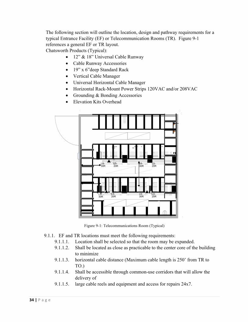
34|P a g e
The following section will outline the location, design and pathway requirements for a typical Entrance Facility (EF) or Telecommunication Rooms (TR). Figure 9-1 references a general EF or TR layout. Chatsworth Products (Typical):
• 12” & 18” Universal Cable Runway • Cable Runway Accessories • 19” x 6”deep Standard Rack • Vertical Cable Manager • Universal Horizontal Cable Manager • Horizontal Rack-Mount Power Strips 120VAC and/or 208VAC • Grounding & Bonding Accessories • Elevation Kits Overhead
Figure 9-1: Telecommunications Room (Typical)
9.1.1. EF and TR locations must meet the following requirements: 9.1.1.1. Location shall be selected so that the room may be expanded. 9.1.1.2. Shall be located as close as practicable to the center core of the building
to minimize 9.1.1.3. horizontal cable distance (Maximum cable length is 250’ from TR to
TO.) 9.1.1.4. Shall be accessible through common-use corridors that will allow the
delivery of 9.1.1.5. large cable reels and equipment and access for repairs 24x7.
AY RACK RELAY K AY RACK REL
L6-30R
L5-20R
L6-30R
L5-20R
L6-30R
L5-20R
L6-30R
L5-20R

35|P a g e
9.1.1.6. In multiple floor applications, EF and TRs shall have all 4 walls vertically stacked.
9.1.1.7. The EF and TRs shall not be part of a server, mechanical, equipment, electrical, washroom, storage area, or a janitor closet. All room locations must be approved in writing by the City prior to construction.
9.1.2. Electromagnetic Interference 9.1.2.1. The EF and TRs shall be located away from sources of electromagnetic
interference. Special attention shall be given to electrical power supply transformers, motors and generators, x-ray equipment, elevator equipment, and induction devices.
9.1.3. Access 9.1.3.1. Access to the Rooms shall be 24 hours-per-day, 365 days-per-year basis
(24x7). Access shall be through common use corridors and not accessed by way of any other room. At a minimum all doors to TR’s will be equipped with a lock and electronic access system.
9.2. DESIGN 9.2.1. Size
9.2.1.1. Rooms shall have a minimum inside dimension of 10ft x 12ft dependent on specific Telecommunication requirements. If these rooms require additional square footage based on additional requirements, the size shall be determined on a case-by-case basis. The City must approve all room dimensions in writing.
9.2.2. Walls 9.2.2.1. All four (4) walls shall be floor to deck and have a 2-hour fire rating.
9.2.3. Plywood Backboards 9.2.3.1. All four (4) walls shall be covered with ¾ in. fire retardant plywood with
fire rating stamp visible on all plywood. To reduce warping, fire-rated plywood shall be kiln-dried to maximum moisture content of 15%.
9.2.3.2. Plywood will not be painted. Mount plywood 2” above the top of the electrical outlets or surface raceway and must be installed vertically. Top of plywood shall be level with the top of the cable tray but shall not exceed 9’6” above finished floor.
9.2.4. Ceiling Height 9.2.4.1. The height between the finished floor and the lowest point of the ceiling
should be a minimum of 14 feet. 9.2.5. Treatment
9.2.5.1. Floors, walls, and ceiling shall be treated to eliminate dust. Finishes shall be light in color to enhance room lighting. Floor covering shall be sealed concrete.
9.2.6. Ceiling 9.2.6.1. Room shall not have a false or drop ceiling to permit maximum use of
cable pathways both vertically and horizontally. In such cases where
36|P a g e
fireproofing may be sprayed onto the exposed ceiling, the fireproofing shall be treated to mitigate airborne dust.
9.2.7. Door 9.2.7.1. Doors shall be a minimum of (42 in) wide and (80 in) high, without
doorsill, hinged to open outward (code permitting) or be removable. Consideration should be given to using double doors with a removable center-post. The door(s) shall be fitted with a lock, which is keyed and electronic access system if available.
9.2.8. Floor Loading 9.2.8.1. The EFs shall be located on floor areas designed with a minimum floor
loading of 4.8 kPa (100 lbf/ft2). The TRs shall be located on floor areas designed with a minimum floor loading of 2.4 kPa (50 lbf/ft2). The project structural engineer shall verify that concentrations of proposed equipment do not exceed the floor-loading limit.
9.3. ENVIRONMENTAL 9.3.1. Contaminants
9.3.1.1. The rooms shall be protected from contaminants and pollutants that could affect operation and material integrity of the installed equipment.
9.3.2. Heating, Ventilation and Air Conditioning (HVAC) 9.3.2.1. HVAC shall be available on a 24 hours-per-day, 365 days-per-year basis.
At a minimum, a stand-alone or dedicated unit shall be considered for all Telecommunication Rooms. It is preferred that two HVAC units are dedicated to the TR, with one being used as a standby backup.
9.3.2.2. HVAC unit shall not be located in the TR. When the HVAC unit must be located in the TR the location needs to be approved by the City.
9.3.2.3. If a standby power source is available in the building, consideration should be given to also connecting the HVAC system serving the Communications Rooms to the standby supply.
9.3.2.4. The temperature and humidity shall be controlled to provide continuous operating ranges of 18°C (64 °F) to 24 °C (76 °F) with 30% to 55% relative humidity.
9.3.2.5. BTU rating requirements shall be calculated on a room-by-room basis due to the nature of the equipment that is being hosted.
9.3.2.6. The ambient temperature and humidity shall be measured at a distance of 1.5 m (5 ft) above the floor level, after the equipment is in operation, at any point along an equipment aisle centerline.
9.3.2.7. A positive pressure differential with respect to surrounding areas should be provided with a minimum of one air change per hour.
9.3.3. Mechanical vibration coupled to equipment or the cabling infrastructure can lead to service failures over time. A common example of this type of failure would be loosened connections. If there is a potential for vibration within the building that will be conveyed to the TR via the building structure, the a structural engineer should design safeguards against excessive TR vibration.

37|P a g e
9.3.4. Mechanical fixtures (e.g., piping, ductwork, pneumatic tubing, electrical conduits) not related to the support of TR/EF shall not be installed in, pass through, under or enter the TR/EF. In addition, the area adjacent to the exterior of the TR/EF walls shall remain clear for cable pathways entering the TR/EF.
1. SUBMIITALS BY CONTRACTOR 1.1. Red-Line Drawings (As-Built Drawings)
1.1.1. On a daily basis, Contractor shall red-line drawings during the course of construction to show the actual alignment or other variances of all installations required by the construction drawings. The drawings shall be available for review by the Owner’s Representative when requested on the job site. Additionally, Contractor shall submit all redline drawings to the Owner’s Project Office on a weekly basis. Under no circumstances shall Contractor proceed with work until acceptable redline drawings are received by Owner for the previous week’s work. Work shutdowns incurred by Contractor due to the failure to provide acceptable redline drawings per this section shall not become the basis for an extension of time or additional compensation to complete the Contract. Contractor shall not submit any application for payment prior to submitting the associated redline "as-built" drawings. Owner shall not make payment for work prior to receiving the associated redline "as-built" drawings. Such drawings shall indicate the location of the installed fiber, cable, conduit, or equipment referenced from permanent landmarks such as mileposts, edge of pavement, bridges, underpasses, handholes, manholes or other permanent markers.
1.2. Daily Progress Report 1.2.1. Contractor’s progress shall be tracked by utilizing Daily Progress Reports. Daily
Progress Reports shall be completed by a Contractor’s Field Representative and signed by the Contractor’s Supervisor with a copy available for the Owner. The Contractor shall note on these forms any discrepancies in progress.
1.3. Contractor’s Construction Schedule 1.3.1. If required by the Owner, Contractor shall submit a revised detailed Microsoft
project resource-loaded construction schedule within five (5) business days of Contract execution for Owner’s approval on an ‘as-needed’ basis determined solely by the Owner. For small jobs Microsoft project resource-loaded construction schedules may not be required, which will be based upon the Owner’s sole judgement. The resource-loaded construction schedule shall include the method(s) by location with the associated quantities, manpower, equipment and production to complete the work. Contractor shall provide Owner this schedule in soft and hard copy form. The schedule shall contain sufficient detail to ensure that Owner can measure Contractor’s progress on a weekly basis throughout the project duration. Owner shall utilize the Daily Progress Report to measure Contractor’s progress. Owner must be notified of any unscheduled delays or recovery plans as necessary.

38|P a g e