cabling of premises for telecommunications
TRANSCRIPT

Cabling of premises for telecommunications
Telstra requirements for customer MDFs
TELSTRA CORPORATION LIMITED (ABN 33 051 775 556) | ISSUED 26/08/2013 ISSUE 2 – FINAL | TELSTRA UNRESTRICTED | DOCUMENT NO. 017153A08 | TELSTRA REQUIREMENTS FOR CUSTOMER MDFS
PAGE 1/45
Author’s name
Business unit
Telstra Operations
Sub-business unit
Access Technology Planning
Issue date
29 August 2013
Issue number
2
Telstra ID
017153a08
Summary
This document sets out Telstra’s requirements for the installation of any main distribution frame (MDF) in
customer premises (referred to herein as a “customer MDF”) that is to be used to connect Telstra’s
copper twisted pair lead-in cabling. It includes the requirements of Australian Standard AS/CA S009,
Installation requirements for customer cabling (Wiring rules).
This document is optimised for reading on a tablet or portable computer to take advantage of hyperlinks,
document search functions and on-screen magnification of photographs and drawings.
This publication has been prepared and written by Telstra Corporation Limited (ABN 33 051 775 556), and is copyright. Other than for the purposes of and subject to the conditions prescribed under the Copyright Act, no part of it may in any form or by any means (electronic, mechanical, microcopying, photocopying, recording or otherwise) be reproduced, stored in a retrieval system or transmitted without prior written permission from the document controller. Product or company names are trademarks or registered trademarks of their respective holders.
Note for non-Telstra readers: The contents of this publication are subject to change without notice. All efforts have been made to ensure the accuracy of this publication. Notwithstanding, Telstra Corporation Limited does not assume responsibility for any errors nor for any consequences arising from any errors in this publication.

Cabling of premises for telecommunications
Telstra requirements for customer MDFs
TELSTRA CORPORATION LIMITED (ABN 33 051 775 556) | ISSUED 26/08/2013 ISSUE 2 – FINAL | TELSTRA UNRESTRICTED | DOCUMENT NO. 017153A08 | TELSTRA REQUIREMENTS FOR CUSTOMER MDFS
PAGE 2/45
CONTENTS 1 PURPOSE ......................................................................................................................................... 4 2 SCOPE .............................................................................................................................................. 4 3 INTRODUCTION ............................................................................................................................... 4
3.1 What is an MDF? .................................................................................................................... 4 3.2 What is not an MDF? .............................................................................................................. 4 3.3 When is an MDF required? .................................................................................................... 5 3.4 Interpretation ........................................................................................................................... 6
4 WIRING RULES REQUIREMENTS FOR CUSTOMER MDFs ....................................................... 6 4.1 General .................................................................................................................................... 6 4.2 Location ................................................................................................................................... 6 4.3 Enclosure ................................................................................................................................ 7 4.4 External (outdoor) MDF .......................................................................................................... 7 4.5 Security ................................................................................................................................... 8 4.6 Access ..................................................................................................................................... 8 4.7 Lighting .................................................................................................................................... 8 4.8 Marking .................................................................................................................................... 8 4.9 Earthing ................................................................................................................................... 8 4.10 Connections ............................................................................................................................ 8 4.11 Records ................................................................................................................................... 9
5 TELSTRA REQUIREMENTS FOR CUSTOMER MDFs ................................................................. 9 5.1 General .................................................................................................................................... 9 5.2 Location ................................................................................................................................... 9 5.3 Cable entrance facilities .......................................................................................................... 9 5.4 Cable termination modules and backmounts ...................................................................... 10 5.5 Marking .................................................................................................................................. 10 5.6 Jumpers ................................................................................................................................. 10
6 CUSTOMER MDF INSTALLATION AND USAGE GUIDELINES ................................................. 10 6.1 MDF location ......................................................................................................................... 10
6.1.1 General.................................................................................................................. 10 6.1.2 Proximity to HV electrical equipment ................................................................... 11 6.1.3 Proximity to the LV electrical switchboard ........................................................... 11 6.1.4 Multi-tenant premises ........................................................................................... 11 6.1.5 Earth Potential Rise (EPR) hazards ..................................................................... 11 6.1.6 General safety hazards ........................................................................................ 12
6.2 Access clearances ................................................................................................................ 12 6.3 Surge suppressor clearance ................................................................................................ 15 6.4 Cabling between the building entry point and the MDF ...................................................... 15 6.5 Home or small office networking distributor ......................................................................... 16 6.6 MDF design ........................................................................................................................... 17
6.6.1 General.................................................................................................................. 17 6.6.2 Small MDFs........................................................................................................... 17 6.6.3 Bay-frame MDFs and MDF racks ........................................................................ 19
6.7 Cable termination modules ................................................................................................... 20 6.8 KRONE backmounts ............................................................................................................ 21 6.9 Cross-connections (jumpers) ............................................................................................... 21 6.10 Connection of cables and jumpers on KRONE modules .................................................... 22 6.11 Tagging of service pairs........................................................................................................ 23 6.12 Double jumpering .................................................................................................................. 24 6.13 Disconnection of dead jumpers ............................................................................................ 25
6.13.1 General.................................................................................................................. 25 6.13.2 Identifying dead jumpers ...................................................................................... 25
6.14 MDF records ......................................................................................................................... 26 6.15 Earthing of MDFs .................................................................................................................. 27 6.16 Surge suppression ................................................................................................................ 30
6.16.1 General.................................................................................................................. 30 6.16.2 Backmount earthing .............................................................................................. 31 6.16.3 Running jumpers where an arrestor magazine is fitted ....................................... 31

Cabling of premises for telecommunications
Telstra requirements for customer MDFs
TELSTRA CORPORATION LIMITED (ABN 33 051 775 556) | ISSUED 26/08/2013 ISSUE 2 – FINAL | TELSTRA UNRESTRICTED | DOCUMENT NO. 017153A08 | TELSTRA REQUIREMENTS FOR CUSTOMER MDFS
PAGE 3/45
6.17 Obsolete solder-tag MDFs.................................................................................................... 32 6.17.1 General.................................................................................................................. 32 6.17.2 Link mounting frames ........................................................................................... 35
6.18 Other obsolete termination equipment ................................................................................. 36 6.19 Contacting Telstra ................................................................................................................. 39
6.19.1 New MDF .............................................................................................................. 39 6.19.2 MDF alterations ..................................................................................................... 39
7 DEFINITIONS .................................................................................................................................. 40 8 REFERENCES ................................................................................................................................ 44 9 DOCUMENT CONTROL SHEET ................................................................................................... 45

Cabling of premises for telecommunications
Telstra requirements for customer MDFs
TELSTRA CORPORATION LIMITED (ABN 33 051 775 556) | ISSUED 26/08/2013 ISSUE 2 – FINAL | TELSTRA UNRESTRICTED | DOCUMENT NO. 017153A08 | TELSTRA REQUIREMENTS FOR CUSTOMER MDFS
PAGE 4/45
1 PURPOSE
This Document sets out Telstra’s requirements for main distribution frames (MDFs) installed in customer
premises (“customer MDFs”) for termination of Telstra copper twisted pair lead-in cables. Some
practical guidance is also provided on the installation and use of customer MDFs.
The Telstra documents may be downloaded from the “Builders” menu of the Telstra Smart Community®
website (http://www.telstra.com.au/smart-community/builders/).
2 SCOPE
This Document applies to the initial installation and any subsequent augmentation (“upgrade”) of a
customer MDF at business or residential premises.
3 INTRODUCTION
3.1 What is an MDF?
A customer MDF is a distributor that terminates, or is intended to terminate, a carrier’s twisted pair
lead-in cabling at the customer’s building. A distributor (known previously as a “distribution frame”) is
used to connect cables that run to different parts of the building from a common point and provides for
cross-connection of cables by means of jumpers or patch cords. Not all distributors are MDFs but all
MDFs are distributors.
There may be more than one MDF in a building (e.g. for termination of different carriers’ networks or
separate twisted pair lead-in cables derived from different technologies).
A customer MDF is supplied and installed by the builder’s, owner’s or customer’s cabling provider as part
of the building telecommunications cabling.
The MDF has a “carrier side” and a “customer side” (commonly referred to as “A” side and “B” side).
The “A” side contains the carrier’s lead-in cable terminations, and the “B” side contains the customer
cabling terminations. Telstra supplies, installs and maintains the termination modules on the “A” side of
the MDF for connection of Telstra network cables.
Cross-connections are made between the “A” side and the “B” side of the MDF using “jumpers”. A
jumper is a pair of twisted, insulated conductors that is connected to the termination modules using a tool
designed for the purpose. Cross-connections in an MDF must not be made by means of patch cords or
“pigtails” (i.e. using plug-connected cords and sockets) for reasons explained in 6.9 on page 21.
An MDF is a defined network boundary point under section 22 of the Telecommunications Act 1997 and,
where used, delineates between a carrier’s (e.g. Telstra’s) network and “customer cabling”. The MDF is
the network boundary for all services supplied through it to customers located in the same premises in
which the MDF is located. The precise location of the network boundary within the MDF is the jumper
terminations on the customer side of the MDF, i.e. “the side of the frame nearest to the end-user”.
The functional elements of a customer MDF are illustrated in Figure 1.
3.2 What is not an MDF?
MDFs are only defined in Australian Standard AS/CA S009, Installation requirements for customer
cabling (Wiring rules), for connection of twisted pair lead-in cables and not for coaxial or optical fibre
lead-in cables. Any device used to connect coaxial or optical fibre lead-in cable is not an MDF.
However, coaxial or optical connections may be included on the customer side of the MDF (e.g. for
connection of coaxial or optical fibre customer cabling to other coaxial or optical fibre customer cabling).
Any device that interconnects cables without jumpers (or patch cords) is not a distributor and,
therefore, cannot be an MDF.
® Registered trade mark of Telstra Corporation Limited

Cabling of premises for telecommunications
Telstra requirements for customer MDFs
TELSTRA CORPORATION LIMITED (ABN 33 051 775 556) | ISSUED 26/08/2013 ISSUE 2 – FINAL | TELSTRA UNRESTRICTED | DOCUMENT NO. 017153A08 | TELSTRA REQUIREMENTS FOR CUSTOMER MDFS
PAGE 5/45
3.3 When is an MDF required?
Telstra considers that a customer MDF is required in one or more of the following circumstances:
two or more carriers will supply services to the premises and share the customer cabling
two or more customers will occupy the premises
the total capacity of the lead-in cabling will be ten (10) pairs or greater (except in the case of a 10-pair
lead-in cable to a home or small business in a rural area — see Note 1)
more than four (4) network lines are to be connected initially (Note 2)
more than eight (8) telecommunications outlet cables are to be connected initially (Note 2).
Notes:
1. 10-pair cable is Telstra’s standard size of lead-in cable for rural areas. While a 10-pair rural lead-in cable may terminate on a Telstra NTD, a 10-pair urban lead-in cable should be terminated on a customer MDF.
2. Telstra’s Network Termination Device (NTD) will connect up to six (6) lines and twelve (12) internal cables for a single customer, which may avoid the need for the use of an MDF in some cases. However, use of this NTD
for new installations is limited to four (4) lines and eight (8) internal cables to allow room for expansion. See Telstra Document No. 012688, Telstra Network Termination Device (NTD) — Information for cabling providers.
Telstra does not normally accept responsibility for cabling on the customer side of the MDF but may use
such cabling to supply a telecommunications service to the point where the customer requires it.
Figure 1 Functional elements of a customer MDF [Figure J18 of AS/CA S009:2013]
Carrier'sterminationmodules
MAIN DISTRIBUTION FRAME (MDF)
Customer'sterminationmodules
Carrierequipment
Jumper
Jumper (Note 2)
Carriercable
Lead-incable
Customercable"Carrier side" "Customer side"
jumper(Note 3)
Customercabling
Jumper (Note 2)
(Note 1) (Note 1)
boundary
Network

Cabling of premises for telecommunications
Telstra requirements for customer MDFs
TELSTRA CORPORATION LIMITED (ABN 33 051 775 556) | ISSUED 26/08/2013 ISSUE 2 – FINAL | TELSTRA UNRESTRICTED | DOCUMENT NO. 017153A08 | TELSTRA REQUIREMENTS FOR CUSTOMER MDFS
PAGE 6/45
3.4 Interpretation
The MDF must meet the compliance labelling requirements of the Australian Communications and
Media Authority (ACMA) and must be installed in accordance with the requirements of Australian
Standard AS/CA S009, Installation requirements for customer cabling (Wiring rules). These
requirements are summarised in this Document. The MDF must also meet Telstra’s requirements as set
out in this Document. Telstra will not connect its lead-in cabling to any customer MDF that does not
meet all requirements.
Notes:
1. The wiring rules (AS/CA S009) may be downloaded free of charge from the Communications Alliance web site at http://www.commsalliance.com.au/Documents/CE-Standards.
2. Other relevant standards (available for purchase from SAI Global www.saiglobal.com) are:
AS/NZS 3084, Telecommunications installations — Telecommunications pathways and spaces for commercial buildings
AS/NZS 3085.1, Telecommunications installations — Administration of communications cabling systems — Basic requirements
AS/NZS 3080, Telecommunications installations — Generic cabling for commercial premises.
In this Document, the use of the words “must”, “must not”, “shall” and “shall not” signify:
a legal obligation;
an important safety, technical or operational requirement; or
a mandatory condition of this Document.
Use of the words “should” or “should not” denote a recommendation of this Document or of a relevant
standard.
Text boxed like this contains an alert or key information.
4 WIRING RULES REQUIREMENTS FOR CUSTOMER MDFs
General
The MDF must comply with the requirements set out in Australian Standards AS/CA S008,
Requirements for customer cabling products, and AS/CA S009, Installation requirements for customer
cabling (Wiring rules). These requirements are summarised below.
Note: Because the MDF is a distributor, it must meet the requirements for all distributors (per section 12 of AS/CA S009) plus the additional MDF requirements (per section 13 of AS/CA S009).
The relevant parts of AS/CA S008:2010 and AS/CA S009:2013 are indicated in brackets [ ].
Note: These standards may be downloaded free of charge from the Communications Alliance web site at http://www.commsalliance.com.au/Documents/CE-Standards.
Location
(a) The proposed location of the MDF should be discussed with the carrier (e.g. Telstra) prior to
installation. [AS/CA S009:2013 Clause 13.3, Note]
(b) The MDF should not be located in the same room as any HV electrical equipment.
[AS/CA S009:2013 Clause 9.1.3.1 Note 2]
(c) The MDF should be located in the same building as the end-user.
[AS/CA S009:2013 Clause 13.3 (a)]
(d) The MDF should be located near the main or first LV electrical switchboard at the building to
enable bonding/earthing of surge suppression devices within the conductor length limits described
in AS/CA S009 (1.5 m/10 m — see 6.15 on page 27 of this Document).
[AS/CA S009:2013 Clause 13.3 (b)]

Cabling of premises for telecommunications
Telstra requirements for customer MDFs
TELSTRA CORPORATION LIMITED (ABN 33 051 775 556) | ISSUED 26/08/2013 ISSUE 2 – FINAL | TELSTRA UNRESTRICTED | DOCUMENT NO. 017153A08 | TELSTRA REQUIREMENTS FOR CUSTOMER MDFS
PAGE 7/45
(e) The MDF shall be structurally robust and shall be securely attached to a permanent building
element such as a wall, floor or column (mounting on hinged panels or wheeled trolleys is not
permitted). [AS/CA S009:2013 Clauses 13.2 (b), 13.3 (d)]
(f) Any MDF installed inside the building shall be installed in a position free from the ingress of dust
and moisture and not subject to damp and/or humid conditions.
[AS/CA S009:2013 Clause 13.3 (c)]
(g) The MDF shall not be installed in any of the following locations:
within any area classified as a hazardous zone [AS/CA S009:2013 Clauses 7.1.2, 7.1.3.7]
in any room containing washing, bathing, shower or toilet amenities
[AS/CA S009:2013 Clause 13.4 (a)]
in a boiler, plant or machine room [AS/CA S009:2013 Clause 13.4 (b)]
in any area subject to corrosive fumes or fluids [AS/CA S009:2013 Clause 13.4 (c)]
in a fire escape stairway [AS/CA S009:2013 Clause 13.4 (d)]
near an automatic sprinkler unless the MDF is provided with a shield to prevent water falling on
it, or all sprinkler heads that could project water onto the MDF have suitable deflectors, or the
sprinkler heads are of the dry type [AS/CA S009:2013 Clause 13.4 (e)]
within a cupboard containing a fire hose reel [AS/CA S009:2013 Clause 13.4 (g)]
near a bath, shower, basin, tub or other fixed water container
[AS/CA S009:2013 Clauses 7.2.2.2 (a) to (c), 13.4 (f)]
near a spa pool, spa tub or swimming pool
[AS/CA S009:2013 Clauses 7.2.2.2 (d) and (e), 13.4 (f)]
near a fountain or water feature [AS/CA S009:2013 Clauses 7.2.2.2 (f), 13.4 (f)]
within a room or enclosure containing a sauna heater
[AS/CA S009:2013 Clauses 7.2.2.2 (g), 13.4 (f)]
within a refrigeration room [AS/CA S009:2013 Clauses 7.2.2.2 (h), 13.4 (f)]
within the hosing down area of any location where general hosing down operations are carried
out. [AS/CA S009:2013 Clauses 7.2.2.2 (i), 13.4 (f)]
Enclosure
(h) Cable entry holes shall be free of sharp edges or burrs or shall have a grommet of insulating
material fitted. [AS/CA S009:2013 Clauses 12.5 (a), 13.2 (a)]
(i) The MDF enclosure shall be designed so as to prevent access to live parts by unqualified
persons.
[AS/CA S009:2013 Clauses 4.4 (a), 12.5 (c), 13.2 (a)]
(j) The MDF enclosure shall be free of exposed sharp edges.
[AS/CA S009:2013 Clauses 12.5 (d), 13.2 (a)]
(k) The enclosure shall provide a minimum clearance of 30 mm between the carrier’s termination
modules and the inside face of the front cover or door of the enclosure in the fully closed position.
[AS/CA S008:2010 Clause 5.4.2.4, AS/CA S009:2013 Clause 13.10]
External (outdoor) MDF
(l) If the MDF is exposed to the weather, it shall have a minimum degree of protection against the
entry of water of IPX3 of AS 60529 or shall be enclosed in an enclosure assessed against the
relevant clauses of AS/CA S008 and that provides a minimum degree of protection of IPX3.
[AS/CA S009:2013 Clauses 12.4 (a), 13.2 (a)]
(m) If the MDF is exposed to the weather, the MDF and the cables connected to it shall be installed in
such a way that a minimum degree of protection of IPX3 of AS 60529 is maintained.
[AS/CA S009:2013 Clauses 12.4 (b), 13.2 (a)]

Cabling of premises for telecommunications
Telstra requirements for customer MDFs
TELSTRA CORPORATION LIMITED (ABN 33 051 775 556) | ISSUED 26/08/2013 ISSUE 2 – FINAL | TELSTRA UNRESTRICTED | DOCUMENT NO. 017153A08 | TELSTRA REQUIREMENTS FOR CUSTOMER MDFS
PAGE 8/45
Security
(n) The MDF, or the enclosure in which it is located, shall have provision for securing with a key,
lock or tool. [AS/CA S009:2013 Clause 13.5]
(o) The building owner, manager or occupant is responsible for the security of the MDF.
[AS/CA S009:2013 Clause 13.5 Note 2]
(p) The MDF should be adequately secured against vandalism and access by children or
unauthorised persons but reasonable access should be given to carriers, carriage service
providers and cabling providers, as required. [AS/CA S009:2013 Clause 13.5 Note 2]
Access
(q) Adequate space shall be provided around the MDF where persons are to pass to enable safe and
convenient access to the MDF and ready escape from the vicinity under emergency conditions.
An MDF is deemed to comply with this requirement if it is installed in accordance with Appendix D
of AS/CA S009 (see Figure 2 to Figure 5 of this Document). [AS/CA S009:2013 Clause 13.6]
(r) Any room containing the MDF shall not require the use of a tool, key, card, number pad or the
like to exit the room. [AS/CA S009:2013 Clause 13.8]
(s) The highest terminal or socket of a wall-mounted MDF (whether internal or external) shall not be
greater than 1800 mm from finished ground or floor level. [AS/CA S009:2013 Clause 13.7.1]
(t) The lowest terminal or socket of any external (wall-mounted) MDF shall not be less than
350 mm from finished ground or floor level. [AS/CA S009:2013 Clause 13.7.2.1]
(u) The lowest terminal or socket of any internal (wall-mounted or floor-mounted) MDF should not
be less than 350 mm from finished ground or floor level. [AS/CA S009:2013 Clause 13.7.2.2]
Lighting
(v) The MDF shall be provided with adequate lighting (a light intensity of 500 lux at a height of 1 metre
above ground or floor level is considered to be adequate lighting).
[AS/CA S009:2013 Clause 13.9]
Marking
(w) The MDF shall:
have the verticals clearly marked alphabetically from left to right, omitting the letters “I” and
“O”; and [AS/CA S009:2013 Clause 13.12 (a)]
have the range of jumperable terminations within each vertical indicated numerically in
ascending order from the lowest module position (unless clearly labelled otherwise) starting
from numeral “1”. [AS/CA S009:2013 Clause 13.12 (b)]
Note: A partially equipped MDF should be marked so as to allow expansion of the MDF without the need to redesignate verticals or renumber existing terminations. [AS/CA S009:2013 Clause 13.12 Note]
Earthing
(x) Provision shall be made for any metallic enclosure, frame or backmount to be earthed (e.g. by
providing suitable holes, screws, bolts or clamps for connection of earthing conductors).
[AS/CA S009:2013 Clauses 12.5 (b), 13.2 (a)]
Connections
(y) The MDF shall be capable of terminating the carrier’s standard termination modules on the
carrier’s side of the MDF (KRONE – manufactured by TE Connectivity – in Telstra’s case).
[AS/CA S009:2013 Clause 13.11]
(z) A carrier’s lead-in cabling or network boundary facilities shall not be moved, removed or altered
without the prior written authorisation of the carrier. [AS/CA S009:2013 Clause 5.13]

Cabling of premises for telecommunications
Telstra requirements for customer MDFs
TELSTRA CORPORATION LIMITED (ABN 33 051 775 556) | ISSUED 26/08/2013 ISSUE 2 – FINAL | TELSTRA UNRESTRICTED | DOCUMENT NO. 017153A08 | TELSTRA REQUIREMENTS FOR CUSTOMER MDFS
PAGE 9/45
(aa) A cabling provider shall not make a connection on the carrier side of the MDF unless a pair on the
carrier side has been tagged, labelled, recorded or otherwise specified by the carrier for the
customer service that is to be connected. [AS/CA S009:2013 Clause 13.13.1]
(bb) A cabling provider may make or alter any connection on the customer side of the MDF.
[AS/CA S009:2013 Clause 13.13.2]
(cc) A cabling provider may remove a redundant cross-connection (“dead jumper”) from the carrier side
of the MDF if all reasonable steps have been taken to ensure that a working service is not
inadvertently disconnected. [AS/CA S009:2013 Clause 13.13.3]
Records
(dd) Suitable cable records shall be provided that enable cables and cross-connections to be correctly
identified and connected. [AS/CA S009:2013 Clauses 12.3.1 (a), 13.2 (a)]
(ee) The records shall be legible and updateable. [AS/CA S009:2013 Clauses 12.3.1 (b), 13.2 (a)]
(ff) Terminations and cross-connections used for any line providing power feeding exceeding 60 V d.c.
or 42.4 V a.c. peak (30 V a.c. r.m.s.), but excluding a line that occasionally carries interrupted ring
voltage (e.g. a standard telephone line), shall be clearly identified in the records and by
appropriate labelling or marking of the MDF connection modules.
[AS/CA S009:2013 Clauses 12.3.2, 13.2 (a)]
5 TELSTRA REQUIREMENTS FOR CUSTOMER MDFs
General
Additional Telstra requirements for customer MDFs are summarised below. These are to ensure that:
the MDF can be safely accessed by Telstra workers;
the customer’s safety is not unduly put at risk;
the safety and integrity of Telstra’s network and services can be reasonably assured; and
the length of cabling from the building entry point to the MDF is minimised.
Location
(1) The MDF should be located in a common service area within 20 metres radial distance of the
Telstra building entry point, subject to the following additional considerations:
The MDF should be installed above known flood levels.
The MDF should be co-located with the building LV electrical switchboard to meet
bonding/earthing requirements, as long as there is no earth potential rise (EPR) hazard.
The MDF should not be installed in an HV electrical switch room or near an HV transformer.
Refer to 6.1.1, 6.1.2 and 6.1.3 of this Document.
(2) The MDF must not be located in an individual tenancy in multi-tenant premises unless the MDF
is solely for the use of that tenant.
Refer to 6.1.4 of this Document.
Cable entrance facilities
(3) The developer, builder, owner or customer is required to provide, or arrange and pay for, the
building penetration and suitable tray, trunking or conduit to support the Telstra lead-in cabling
from the building entry point to the MDF. Facilities shared with other services are acceptable
subject to the appropriate separations being maintained.
Refer to 6.4 of this Document.

Cabling of premises for telecommunications
Telstra requirements for customer MDFs
TELSTRA CORPORATION LIMITED (ABN 33 051 775 556) | ISSUED 26/08/2013 ISSUE 2 – FINAL | TELSTRA UNRESTRICTED | DOCUMENT NO. 017153A08 | TELSTRA REQUIREMENTS FOR CUSTOMER MDFS
PAGE 10/45
Cable termination modules and backmounts
(4) Telstra’s standard terminating system for customer premises is the KRONE Series 2 Disconnection
Module, Profil. The MDF must include sufficient module backmounts on the Telstra side of the
MDF to enable Telstra to fit the KRONE modules and connect the Telstra lead-in cable at the MDF.
Telstra will not connect its lead-in cable to any other terminating system under any circumstances.
Note: KRONE is manufactured by TE Connectivity Ltd.
Refer to 6.6 and 6.7 of this Document.
(5) The backmounts used for the KRONE modules may be either the Profil or turret (notched) style.
Refer to 6.7 and 6.8 of this Document.
(6) Telstra services must be connected to the customer cabling by means of jumpers. Telstra will not:
connect its lead-in cables to any modules that are hard-wired or pre-jumpered to other
connection modules or customer cabling; or
connect its lead-in cables to any patch panel or to any termination module that is hard-wired to
a patch panel.
Refer to 6.9 of this Document.
Marking
(7) The customer side of the MDF should be marked in the same way as the Telstra side to avoid
confusion, e.g. if the existing Telstra-side terminations are numbered from the bottom up, then the
customer-side terminations should be numbered from the bottom up.
Jumpers
(8) No more than one jumper may be connected to any pair of terminals on Telstra’s side of the MDF.
Refer to 6.12 of this Document.
6 CUSTOMER MDF INSTALLATION AND USAGE GUIDELINES
6.1 MDF location
6.1.1 General
While the MDF may be located either internally or on an external wall of the building, it should be
installed inside the building for reasons of economy, reliability and security. Where the MDF is located
externally, it must be installed in a suitable enclosure to protect it from the weather, access by children or
unauthorised persons, and physical damage (e.g. vandalism). External MDFs are commonly locked by
the owner or customer. In such cases, if it is not obvious where a key can be obtained to access the
MDF, this should indicated by a durable notice on or beside the MDF.
The MDF should be located in the same building as the customer. An MDF should not be used to
feed multiple tenants located in separate buildings. Refer to 0 (c).
Note: A single MDF may be used to connect multiple buildings occupied by the same customer unless the buildings are under separate leases or are likely to be sub-leased (see 6.1.4).
The MDF should be located in a common service area within 20 metres radial distance of the Telstra
building entry point subject to the following additional considerations:
The MDF should be installed above known flood levels.
The MDF should be co-located with the building LV electrical switchboard to meet bonding/
earthing requirements, as long as it will not be near any HV electrical equipment and there is no earth
potential rise (EPR) hazard.
More information is provided below.

Cabling of premises for telecommunications
Telstra requirements for customer MDFs
TELSTRA CORPORATION LIMITED (ABN 33 051 775 556) | ISSUED 26/08/2013 ISSUE 2 – FINAL | TELSTRA UNRESTRICTED | DOCUMENT NO. 017153A08 | TELSTRA REQUIREMENTS FOR CUSTOMER MDFS
PAGE 11/45
6.1.2 Proximity to HV electrical equipment
The MDF should not be installed in an HV electrical switch room or within 15 metres of any HV
transformer, whether either the MDF or the HV transformer is internal or external to the building.
6.1.3 Proximity to the LV electrical switchboard
Whether the MDF is located internally or externally, it should be installed within a few metres of the
building LV electrical switchboard (i.e. the switchboard in/on the customer’s building) to minimise the
equipotential bonding conductor length for connection of lightning surge suppression (see 6.15).
6.1.4 Multi-tenant premises
In multi-tenant premises, the customer MDF should be located in a common service area of the same
building in which the customer (tenant) is located.
The MDF must not be located in an individual tenancy in multi-tenant premises unless the MDF is
provided solely for the use of that tenant.
Notes:
1. Apart from security and privacy concerns, the installation of a common MDF in an individual tenancy may create access problems for Telstra and other service providers, and may cause inconvenience to that tenant and to the other tenants who rely on that tenant’s goodwill for connection and repair of their telecommunications services.
2. Telstra may refuse to connect a telecommunications service to any MDF that is located in a tenancy other than that of the customer being supplied with the service.
6.1.5 Earth Potential Rise (EPR) hazards
For safety reasons, an MDF must not be installed within an EPR hazard zone. The cabling provider
must survey the premises for the presence of power poles, towers, transformers and substations (i.e.
located in the street, within the customer’s premises or within adjoining premises) to ensure that the
MDF will not be installed within an EPR hazard zone.
As a general rule, the MDF should not be installed:
within 40 metres radial distance of the base of a steel lattice tower or metal or concrete pole
supporting HV power lines of 220 kV or higher
within 16 metres radial distance of the base of a steel lattice tower, metal or concrete pole, or a
wooden pole with a down-conductor to an earth electrode, supporting HV power lines of 66 kV or
132 kV
within 15 metres radial distance of:
o a pole supporting HV power lines less than 66 kV and with any connections to underground
power cable
o a pole supporting an HV power transformer
o a metal or concrete pole, or a wooden pole with a down-conductor to an earth electrode,
supporting HV power lines less than 66 kV
o a wooden pole supporting HV power lines with a pole-top switch and either an all-metal down-
rod or an earthing conductor extending up the pole above the handle
o a pad-mounted (ground level) HV power transformer
within the minimum distance of a power generating station or a power distribution substation specified
by the relevant power utility.
Refer to Appendix H of Australian Standard AS/CA S009 (Wiring Rules) or to Australian Standard
AS 3835.1 for more information.
Where the entire building is within an EPR hazard zone (e.g. a power generating station or a power
distribution substation), the lead-in cabling may need special isolation equipment to be fitted at the
building entry point or telecommunications services may need to be supplied by means of optical fibre or
wireless technology. In such cases, the cabling provider must liaise with Telstra, through the relevant
power utility, for safe connection of telecommunications services.

Cabling of premises for telecommunications
Telstra requirements for customer MDFs
TELSTRA CORPORATION LIMITED (ABN 33 051 775 556) | ISSUED 26/08/2013 ISSUE 2 – FINAL | TELSTRA UNRESTRICTED | DOCUMENT NO. 017153A08 | TELSTRA REQUIREMENTS FOR CUSTOMER MDFS
PAGE 12/45
6.1.6 General safety hazards
Notwithstanding anything contained in this Document or any other document, the MDF must not be
installed in any location or in such a way that may put the health or safety of any person required to work
on the MDF at risk. For example, an MDF should not be located in a vehicle driveway or vehicle parking
area without the provision of suitable barriers to protect a person working on the MDF from being struck
by a moving vehicle.
6.2 Access clearances
Suitable access clearances are required around the customer MDF to provide safe and convenient
access to carriers, service providers and cabling providers. The access space is necessary to provide a
person with sufficient head and shoulder room to terminate cables, test services and make cross-
connections on the MDF. The area above, below and beside the MDF should not contain any protruding
obstacles that may require any person to stoop or twist their body in order to gain access to cables or
terminations within the MDF.
Where any MDF termination is installed at a height that requires the use of a ladder (this is only
permissible for a floor-mounted or “island” MDF), additional clearance may be required around the MDF
to allow positioning and climbing of the ladder safely and/or safe passage around the ladder.
Figure 2 to Figure 5 illustrate minimum and maximum heights and clearances recommended to ensure
that the installation complies with the mandatory requirements of AS/ACIF S009 and to ensure safe and
convenient access.
Figure 2 Installation zone for a wall mounted MDF on the external wall of a building
[Figure D1 of AS/CA S009:2013]
Finished
350 mm
The shaded area indicatesthe preferred zone forlocation of the MDF
1800 mm
ground level
Electrical switchboard
1 m(Note 1)
1 m(Note 1)
150 mm minimum clearance(Note 2)
Notes:
1. It is recommended that the MDF be installed within 1 metre of the electrical switchboard for ready location, access and to enable effective surge suppression to be provided. Care needs to be taken to avoid building fixtures such as downpipes, water pipes/taps, etc. and fences that adjoin the building.
2. The 150 mm clearance is an operational clearance (e.g. to allow for opening of the door/cover of the MDF or future expansion), and is not a safety requirement.

Cabling of premises for telecommunications
Telstra requirements for customer MDFs
TELSTRA CORPORATION LIMITED (ABN 33 051 775 556) | ISSUED 26/08/2013 ISSUE 2 – FINAL | TELSTRA UNRESTRICTED | DOCUMENT NO. 017153A08 | TELSTRA REQUIREMENTS FOR CUSTOMER MDFS
PAGE 13/45
Figure 3 Access clearances for a wall-mounted MDF
[Figure D2 of AS/CA S009:2013]
All dimensions are in mm.
The required clear access spaceis indicated by the shaded area
2000min.
Side view Front view
See Figure 4
1800max.
350Min.
Wall
Finished ground or floor level
MDF cableterminations
Enclosure
MDF cable
terminations
Enclosure
min.900
min.900
Figure 4 Access clearances for a wall-mounted MDF
[Figure D3 of AS/CA S009:2013]
Enclosure
Plan view
300(Note 2)
300(Note 2)
900 min.(Note 2)
900 min.
Wall
MDF
All dimensionsare in mm.
Notes:
1. The shaded area indicates the space that should be kept clear of obstacles.
2. The 300 mm side clearance provides “shoulder room” for working on the MDF. The minimum required total clearance width in front of the device is 900 mm.

Cabling of premises for telecommunications
Telstra requirements for customer MDFs
TELSTRA CORPORATION LIMITED (ABN 33 051 775 556) | ISSUED 26/08/2013 ISSUE 2 – FINAL | TELSTRA UNRESTRICTED | DOCUMENT NO. 017153A08 | TELSTRA REQUIREMENTS FOR CUSTOMER MDFS
PAGE 14/45
Figure 5 Access clearances for a floor-mounted (“island”) MDF
[Figure D4 of AS/CA S009:2013]
MDF ROOM
Door
900 mm
Y
900 mm
X MDF
Z - - -
A - - -
- - - Q
- - - J
Notes:
1. Position the MDF within the room to obtain the required minimum clearances around it.
2. The fixed end clearance, marked “X”, must be sufficient to provide “shoulder room” for working on the MDF, i.e. a
minimum of 300 mm. However, sufficient clearance should be provided to enable ready escape from the vicinity under emergency conditions — a minimum distance of 600 mm is recommended for this purpose. If the MDF has cable terminations facing the end wall, a minimum distance of 900 mm is required.
3. The end clearance marked ‘”Y” should be sufficient to provide for MDF expansion, access and ready escape
from the vicinity under emergency conditions — a minimum distance of 1200 mm is recommended.
4. A minimum frontal clearance of 900 mm working space from the vertical face of the termination side of the MDF and a minimum vertical clearance of 2 m from the walked-on surface are required.
5. The MDF verticals must be designated alphabetically from left to right (i.e. in an anti-clockwise direction) as shown. A gap should be provided in the vertical designations as indicated above (e.g. K-P) to allow for verticals to be added later without the need to redesignate the existing verticals.

Cabling of premises for telecommunications
Telstra requirements for customer MDFs
TELSTRA CORPORATION LIMITED (ABN 33 051 775 556) | ISSUED 26/08/2013 ISSUE 2 – FINAL | TELSTRA UNRESTRICTED | DOCUMENT NO. 017153A08 | TELSTRA REQUIREMENTS FOR CUSTOMER MDFS
PAGE 15/45
6.3 Surge suppressor clearance
A minimum clearance of 30 mm is required between the front face of the Telstra termination modules
and the inside face of the front cover or door of the MDF enclosure in the fully closed position. This
clearance is to provide for fitting of gas arrestor magazines. See Figure 6.
Figure 6 Clearances within an MDF enclosure
60 mm
60 mm 60 mm
Terminations
60 mm
Enclosure door opening
30 mm
Door
Terminations
Side viewFront view
Enclosure
Notes:
1. A minimum clearance of 30 mm is required in front of the Telstra modules to allow for fitting of surge suppression devices (this is requirement of the wiring rules).
2. Sufficient clearance is required around the termination modules to connect cables and run jumpers. While the wiring rules do not specify access clearances for this purpose, a minimum clearance of 60 mm is recommended between the modules and the sides of the MDF enclosure to provide “finger access” to the jumpers at the sides of the modules.
6.4 Cabling between the building entry point and the MDF
For internal MDFs, the building owner should provide suitable lead-in cable entry facilities and a suitable
pathway for running the lead-in cable between the “building entry point” (cable entry point) and the MDF.
Facilities such as cable trays or trunking shared with other services are acceptable subject to the
appropriate separations being maintained.
Note: Telstra requires the internal lead-in cabling to be separated from other services in accordance with the relevant requirements of sections 8, 9 and 16 of the wiring rules (AS/CA S009), which may be downloaded from the Communications Alliance website http://www.commsalliance.com.au/Documents/CE-Standards.
Cabling of premises for telecommunications
Telstra requirements for customer MDFs
TELSTRA CORPORATION LIMITED (ABN 33 051 775 556) | ISSUED 26/08/2013 ISSUE 2 – FINAL | TELSTRA UNRESTRICTED | DOCUMENT NO. 017153A08 | TELSTRA REQUIREMENTS FOR CUSTOMER MDFS
PAGE 16/45
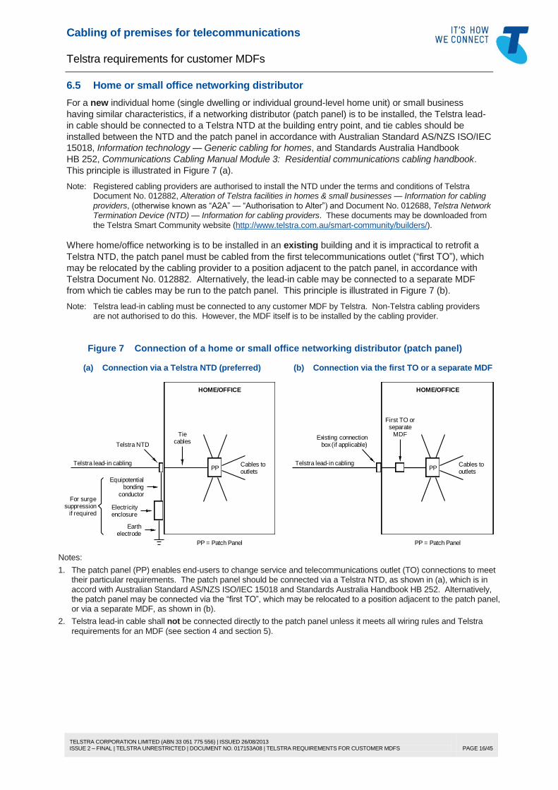
6.5 Home or small office networking distributor
For a new individual home (single dwelling or individual ground-level home unit) or small business
having similar characteristics, if a networking distributor (patch panel) is to be installed, the Telstra lead-
in cable should be connected to a Telstra NTD at the building entry point, and tie cables should be
installed between the NTD and the patch panel in accordance with Australian Standard AS/NZS ISO/IEC
15018, Information technology — Generic cabling for homes, and Standards Australia Handbook
HB 252, Communications Cabling Manual Module 3: Residential communications cabling handbook.
This principle is illustrated in Figure 7 (a).
Note: Registered cabling providers are authorised to install the NTD under the terms and conditions of Telstra Document No. 012882, Alteration of Telstra facilities in homes & small businesses — Information for cabling providers, (otherwise known as “A2A” — “Authorisation to Alter”) and Document No. 012688, Telstra Network Termination Device (NTD) — Information for cabling providers. These documents may be downloaded from the Telstra Smart Community website (http://www.telstra.com.au/smart-community/builders/).
Where home/office networking is to be installed in an existing building and it is impractical to retrofit a
Telstra NTD, the patch panel must be cabled from the first telecommunications outlet (“first TO”), which
may be relocated by the cabling provider to a position adjacent to the patch panel, in accordance with
Telstra Document No. 012882. Alternatively, the lead-in cable may be connected to a separate MDF
from which tie cables may be run to the patch panel. This principle is illustrated in Figure 7 (b).
Note: Telstra lead-in cabling must be connected to any customer MDF by Telstra. Non-Telstra cabling providers are not authorised to do this. However, the MDF itself is to be installed by the cabling provider.
Figure 7 Connection of a home or small office networking distributor (patch panel)
(a) Connection via a Telstra NTD (preferred) (b) Connection via the first TO or a separate MDF
cablesTie
PPCables tooutlets
PP = Patch Panel
HOME/OFFICE
Telstra NTD
suppressionif required
For surge
Telstra lead-in cabling
Equipotentialbonding
Electricityenclosure
Earth
conductor
electrode
box (if applicable)
PPCables tooutlets
PP = Patch Panel
HOME/OFFICE
Existing connection
Telstra lead-in cabling
MDFseparate
First TO or
Notes:
1. The patch panel (PP) enables end-users to change service and telecommunications outlet (TO) connections to meet their particular requirements. The patch panel should be connected via a Telstra NTD, as shown in (a), which is in accord with Australian Standard AS/NZS ISO/IEC 15018 and Standards Australia Handbook HB 252. Alternatively, the patch panel may be connected via the “first TO”, which may be relocated to a position adjacent to the patch panel, or via a separate MDF, as shown in (b).
2. Telstra lead-in cable shall not be connected directly to the patch panel unless it meets all wiring rules and Telstra
requirements for an MDF (see section 4 and section 5).

Cabling of premises for telecommunications
Telstra requirements for customer MDFs
TELSTRA CORPORATION LIMITED (ABN 33 051 775 556) | ISSUED 26/08/2013 ISSUE 2 – FINAL | TELSTRA UNRESTRICTED | DOCUMENT NO. 017153A08 | TELSTRA REQUIREMENTS FOR CUSTOMER MDFS
PAGE 17/45
6.6 MDF design
6.6.1 General
There are numerous brands and styles of customer MDFs available. Smaller MDFs may be supplied as
a complete unit whereas larger MDFs are usually assembled on site using ACMA-compliant
components. In the latter case, products must be selected and used according to the relevant
requirements for MDFs of Australian Standards AS/CA S008, Requirements for customer cabling
products, and AS/ACIF S009, Installation requirements for customer cabling (Wiring rules).
The cable terminating system used on the customer side (“B” side) of the MDF may be any ACMA-
compliant type. However, the terminating system used on the carrier side (“A” side) of the MDF must be
the carrier’s standard terminating system for customer MDFs (KRONE Series 2 Profil-mount
Disconnection Modules in Telstra’s case). Other carriers may use different terminating systems, so it is
important to ascertain what terminating systems they use for customer MDFs.
Notes:
1. Telstra uses assorted cable terminating systems for various applications. For example, Telstra uses different terminating systems in exchange MDFs, roadside cabinets and pillars. However, only KRONE (TE Connectivity) Series 2 Disconnection Modules (Profil) may be used for terminating Telstra lead-in cables on customer MDFs.
2. While the installer of the customer MDF must ensure that the MDF is capable of terminating KRONE Series 2 modules on the Telstra side of the MDF (e.g. by providing suitable backmounts), the termination modules themselves will be supplied and installed by Telstra.
Where the “B” side of the customer MDF is not KRONE or KRONE compatible, it may be necessary for
the building owner, manager or customer, as applicable, to make suitable terminating tools and usage
instructions available at the MDF for use by carriers and service providers or, alternatively, arrange for
their own cabling provider to connect service jumpers to the “B” side of the MDF as and when required
(see 6.11 on page 23).
6.6.2 Small MDFs
The KRONE 10-pair MDF illustrated in Figure 8 is a popular MDF for termination of lead-in cable up to
10 pairs and is an example of a style of MDF that uses vertically orientated termination modules.
With this particular MDF, the “A” side termination module is supplied with it (the module is moulded into
the base). The MDF has limited capacity for termination of customer (“B” side) cables, and its use
should be limited to simple network interfacing applications, such as shown in Figure 7 (b), or for cases
where no more than 8 to 10 customer cable pairs are ever likely to be terminated. Figure 8 shows how
cables and jumpers are terminated on this MDF.
Other types of MDF that use the same vertical module mounting arrangement (e.g. Madison Model 30
MDF) are similarly terminated.

Cabling of premises for telecommunications
Telstra requirements for customer MDFs
TELSTRA CORPORATION LIMITED (ABN 33 051 775 556) | ISSUED 26/08/2013 ISSUE 2 – FINAL | TELSTRA UNRESTRICTED | DOCUMENT NO. 017153A08 | TELSTRA REQUIREMENTS FOR CUSTOMER MDFS
PAGE 18/45
Figure 8 10-pair KRONE MDF
Customer cables
Lead-in cable(s)
Cable tie posts
Earthing strip
Screw terminals for6 mm² and 2.5 mm²
earth cables
Bonding conductorif required (Note 5)
Earthing bar
Jumperguides
Jumpers
Cable tie posts
'A'strip
'B'strip
Terminationmodules
Form a "gooseneck"in the conductors
before terminating
Notes:
1. This particular MDF is for internal (indoor) use only but may be used outdoors if housed in a suitable weather resistant enclosure. It has a deep cover to accommodate a KRONE arrestor magazine. The 10-pair KRONE MDF should not be confused with the KRONE 20-pair Final Distribution Point, which looks similar but has a shallow cover and no metal strap between the earth bar and the “A” side module for an arrestor magazine. The 20-pair FDP must not be used as an MDF.
2. The “A” strip is reserved for carrier cables. The “B” strip is used for connection of customer cables. This MDF has no room for expansion and should only be used where no more than 8 to 10 customer cable pairs are ever likely to be terminated.
3. Terminate cables on the left (unnumbered) side of the module, and connect jumpers on the right (numbered) side of the module, as shown above. Leave a “gooseneck” in the cable conductors to allow for disconnection and re-termination of conductors for testing purposes. Leave sufficient slack in the jumpers to enable them to be traced.
4. A genuine KRONE terminating tool should be used for terminating cables on this MDF. Other brands of tool should not be used. Use of a non-KRONE tool may damage the modules.
5. The earthing bar of the MDF should be equipotentially bonded to the electrical earthing system in accordance with Australian Standard AS/CA S009 (wiring rules) to facilitate the installation of effective surge suppression for the protection of the end-users of the telecommunications services. See 6.16 (page 30) for more information.
MDFs are available as frame assemblies on which the required number of termination modules may be
mounted. These are available for indoor or outdoor use. Some MDFs used for termination of lead-in
cables of 10 to 50 pairs may only contain one backmount or “vertical” for mounting of both “A” side and
“B” side termination modules. In such cases, the demarcation between the “A” side and the “B” side of
the MDF may be less obvious than with larger MDFs that have several verticals.
A typical single vertical MDF is illustrated in Figure 9.
Cabling of premises for telecommunications
Telstra requirements for customer MDFs
TELSTRA CORPORATION LIMITED (ABN 33 051 775 556) | ISSUED 26/08/2013 ISSUE 2 – FINAL | TELSTRA UNRESTRICTED | DOCUMENT NO. 017153A08 | TELSTRA REQUIREMENTS FOR CUSTOMER MDFS
PAGE 19/45
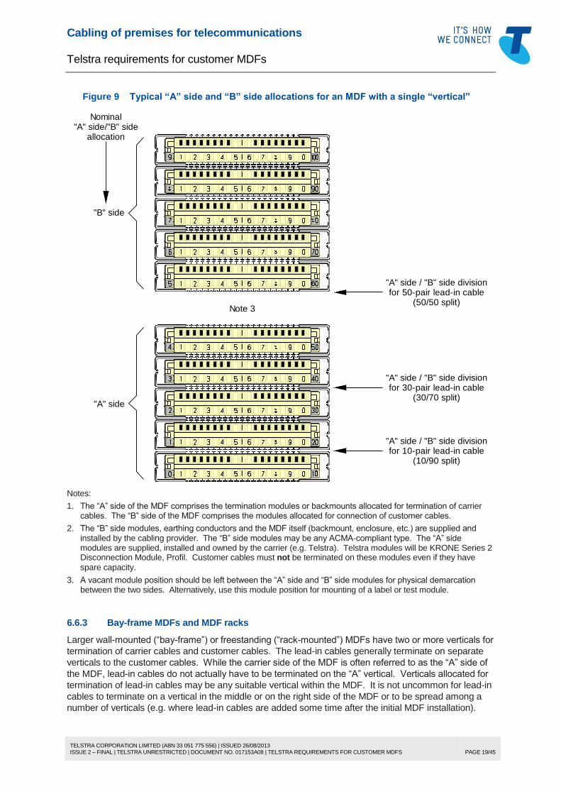
Figure 9 Typical “A” side and “B” side allocations for an MDF with a single “vertical”
for 30-pair lead-in cable"A" side / "B" side division
(30/70 split)
for 10-pair lead-in cable"A" side / "B" side division
(10/90 split)
"A" side
for 50-pair lead-in cable"A" side / "B" side division
(50/50 split)
"B" side
Nominal"A" side/"B" side
allocation
Note 3
Notes:
1. The “A” side of the MDF comprises the termination modules or backmounts allocated for termination of carrier cables. The “B” side of the MDF comprises the modules allocated for connection of customer cables.
2. The “B” side modules, earthing conductors and the MDF itself (backmount, enclosure, etc.) are supplied and installed by the cabling provider. The “B” side modules may be any ACMA-compliant type. The “A” side modules are supplied, installed and owned by the carrier (e.g. Telstra). Telstra modules will be KRONE Series 2 Disconnection Module, Profil. Customer cables must not be terminated on these modules even if they have
spare capacity.
3. A vacant module position should be left between the “A” side and “B” side modules for physical demarcation between the two sides. Alternatively, use this module position for mounting of a label or test module.
6.6.3 Bay-frame MDFs and MDF racks
Larger wall-mounted (“bay-frame”) or freestanding (“rack-mounted”) MDFs have two or more verticals for
termination of carrier cables and customer cables. The lead-in cables generally terminate on separate
verticals to the customer cables. While the carrier side of the MDF is often referred to as the “A” side of
the MDF, lead-in cables do not actually have to be terminated on the “A” vertical. Verticals allocated for
termination of lead-in cables may be any suitable vertical within the MDF. It is not uncommon for lead-in
cables to terminate on a vertical in the middle or on the right side of the MDF or to be spread among a
number of verticals (e.g. where lead-in cables are added some time after the initial MDF installation).

Cabling of premises for telecommunications
Telstra requirements for customer MDFs
TELSTRA CORPORATION LIMITED (ABN 33 051 775 556) | ISSUED 26/08/2013 ISSUE 2 – FINAL | TELSTRA UNRESTRICTED | DOCUMENT NO. 017153A08 | TELSTRA REQUIREMENTS FOR CUSTOMER MDFS
PAGE 20/45
Fitting and termination of lead-in termination modules on larger MDFs are the same as for smaller MDFs
(see 6.8).
For information about obsolete solder-tag MDFs, see 6.17 on page 32.
Figure 10 Typical bay-frame MDF layout
O
T
H
E
R
500 500 500 500 500 500 500 500
A B C D E F S T
Customer cabling termination modulesCarrier termination modules
1 1 1 1 1 1 1 1
(MDF "A" side or "carrier" side) (MDF "B" side or "customer" side)
T
E
L
S
T
R
A
Service jumper(e.g. phone/DSL)
C
A
R
R
I
E
R
O
T
H
E
R
C
A
R
R
I
E
R
Jumper rings
T
E
L
S
T
R
A
Notes:
1. While it is preferred that the network terminations be at the left-hand end of the MDF, this is not always achievable and by no means essential. Nevertheless, verticals should be selected, where possible, such that all of a particular carrier's verticals/modules are adjacent whether or not they also happen to be adjacent to the other carrier's verticals/modules.
2. In the above example, verticals A + B and C + D would be set aside for Telstra and other carriers’ lead-in cables and termination of each carrier's network equipment.
6.7 Cable termination modules
It is a wiring rules requirement for the MDF to be capable of accommodating the carrier’s standard cable
termination modules on the “A” side so that the carrier can install these modules in the MDF and
terminate the lead-in cable on them. Telstra’s standard cable termination module for use on customer
MDFs is as follows:
KRONE Series 2 Disconnection Module (1-0), Profil Mount, 10-pair,
Telstra serial/item 537/171, TE Connectivity Product No. 6468 5 043-10 (Box of 10)
This module will mount on either a Profil (rod) or turret (notched) style KRONE backmount (see 6.8) and
will terminate 0.40 mm to 0.64 mm diameter solid copper conductors. It is not suitable for terminating
0.90 mm diameter conductors.
Telstra will not agree to terminate its lead-in cable on any other type of connection module.

Cabling of premises for telecommunications
Telstra requirements for customer MDFs
TELSTRA CORPORATION LIMITED (ABN 33 051 775 556) | ISSUED 26/08/2013 ISSUE 2 – FINAL | TELSTRA UNRESTRICTED | DOCUMENT NO. 017153A08 | TELSTRA REQUIREMENTS FOR CUSTOMER MDFS
PAGE 21/45
The installer of the MDF should ensure that sufficient backmounts are provided for Telstra to be able to
terminate all lead-in cable pairs. Additional capacity of at least 50% should also be provided for future
expansion.
The connection modules for termination of Telstra’s lead-in cable will be supplied and installed on the
backmounts, and the lead-in cable terminated on the modules, by Telstra.
Non-Telstra cabling providers must not terminate Telstra lead-in cable on any MDF unless authorised in
writing by a Telstra person with the authority to do so for that specific MDF.
6.8 KRONE backmounts
Two styles of KRONE backmount may be used for mounting the Telstra termination modules:
rod (“Profil”) type, as shown in Figure 17; or
turret (notched) type, as shown in Figure 18.
Telstra does not have any preference for the style of backmount used — either type is suitable.
At least one type of small MDF, described in 6.6.2 and illustrated in Figure 8, includes both the “A” side
and “B” side modules moulded into the base, such that none of the above backmounts is required.
6.9 Cross-connections (jumpers)
Telstra services must be connected to the customer cabling by means of jumpers. Telstra will not
connect its copper twisted pair lead-in cabling to:
any cable distribution device that does not use jumpers other than the Telstra NTD described in
Telstra Document No. 012688;
any modules that are hard-wired or pre-jumpered en masse to other connection modules or customer
cabling; or
any patch panel or any MDF termination module that is hard-wired to a patch panel.
Note: Jumpers provide Telstra some control over connection of network services to customer cabling to prevent such things as accidental connection of power feed pairs to a customer’s telecommunications outlet (prohibited by Communications Alliance Code C559 Part 1) or accidental connection of a service intended for another customer or another address.
Service jumpers (i.e. jumpers from the “A” side to the “B” side of the MDF to connect a Telstra network
service) are normally run by Telstra. However, Telstra may require the customer’s service provider or
cabling provider to run the jumper or to connect the “B” end of the jumper if:
the “B” side pair has not been tagged or otherwise identified beforehand by the service provider or
cabling provider; or
the Telstra installer does not have a suitable terminating tool to connect the “B” end of the jumper on
the “B” side termination modules, which may be a type that Telstra is not familiar with.
A non-Telstra cabling provider is permitted to run a service jumper to connect a new service if, and only
if, the “A” side pair has been tagged or otherwise identified in writing by Telstra for the specific purpose
of authorising a cabling provider to connect a jumper to that pair (see 6.11 on page 23).
A non-Telstra cabling provider may make or alter any connection on the “B” side of the MDF.
A non-Telstra cabling provider may remove a “dead” jumper (e.g. to free up a pair on the “B” side of the
MDF) if all reasonable steps have been taken to ensure that a working service is not accidentally
disconnected (see 6.13 page 25).

Cabling of premises for telecommunications
Telstra requirements for customer MDFs
TELSTRA CORPORATION LIMITED (ABN 33 051 775 556) | ISSUED 26/08/2013 ISSUE 2 – FINAL | TELSTRA UNRESTRICTED | DOCUMENT NO. 017153A08 | TELSTRA REQUIREMENTS FOR CUSTOMER MDFS
PAGE 22/45
6.10 Connection of cables and jumpers on KRONE modules
The cabling provider shall terminate any jumper on a Telstra “A” side MDF module in accordance with
the KRONE Technical Manual, using either of the following tools:
KRONE “S” (Sensor) Connection Tool, TE Connectivity Product No. 6417 2 055-01; or
KRONE Connection Tool, TE Connectivity Product No. 6089 2 003-00.
No other brand of tool may be used for termination of jumpers on the Telstra (“A” side) modules.
Guidelines for termination of cables and jumpers on KRONE modules are provided in Figure 11 and
Figure 12.
Telstra lead-in cables must be terminated by Telstra.
Figure 11 Termination of cables or jumpers on KRONE Series 2 modules
Module mounting turret
Align the terminating tool at
Backmount
150 mm slackAt least
Termination module
formed in agooseneck
in the channelCables formed
behind themodules
90° to the front of the module
Push the tool in until it clicks
SIDE VIEW
Cutting scissor
Notes:
1. The KRONE modules may be mounted on a turret style backmount (shown above) or a Profil (rod style) backmount (see Figure 17 on page 29).
2. Remove the cable sheath about 30 mm to 50 mm into the frame unit or backmount. Tie the cable sheath lightly to the frame unit or backmount using a suitable cable tie.
3. Leave at least 150 mm slack in the cable pairs in a “gooseneck” behind each module so that the module can be removed or swung out (Profil) from the backmount for inspection, maintenance, or to gain access behind the modules to add cables. Lightly bind or tie the conductors into 10-pair tails for termination on each module.
4. A genuine KRONE terminating tool should be used for terminating cables or jumpers on KRONE modules. Use of any other brand of tool may damage the modules.
5. Terminate cables from the bottom up, i.e. fan out and terminate the first 10 pairs on the bottom module, then fan out and terminate the second 10 pairs on the second module, and so on. Refer to Figure 12.
Cabling of premises for telecommunications
Telstra requirements for customer MDFs
TELSTRA CORPORATION LIMITED (ABN 33 051 775 556) | ISSUED 26/08/2013 ISSUE 2 – FINAL | TELSTRA UNRESTRICTED | DOCUMENT NO. 017153A08 | TELSTRA REQUIREMENTS FOR CUSTOMER MDFS
PAGE 23/45
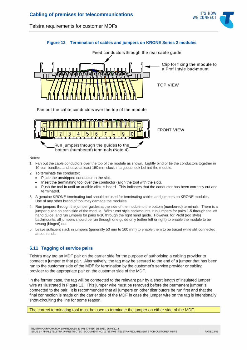
Figure 12 Termination of cables and jumpers on KRONE Series 2 modules
Fan out the cable conductors over the top of the module
Run jumpers through the guides to the
FRONT VIEW
TOP VIEW
bottom (numbered) terminals (Note 4)
Feed conductors through the rear cable guide
Clip for fixing the module toa Profil style backmount
Notes:
1. Fan out the cable conductors over the top of the module as shown. Lightly bind or tie the conductors together in 10-pair bundles, and leave at least 150 mm slack in a gooseneck behind the module.
2. To terminate the conductor:
Place the unstripped conductor in the slot.
Insert the terminating tool over the conductor (align the tool with the slot).
Push the tool in until an audible click is heard. This indicates that the conductor has been correctly cut and terminated.
3. A genuine KRONE terminating tool should be used for terminating cables and jumpers on KRONE modules. Use of any other brand of tool may damage the modules.
4. Run jumpers through the jumper guides at the side of the module to the bottom (numbered) terminals. There is a jumper guide on each side of the module. With turret style backmounts, run jumpers for pairs 1-5 through the left hand guide, and run jumpers for pairs 6-10 through the right hand guide. However, for Profil (rod style) backmounts, all jumpers should be run through one guide only (either left or right) to enable the module to be swung (hinged) out.
5. Leave sufficient slack in jumpers (generally 50 mm to 100 mm) to enable them to be traced while still connected at both ends.
6.11 Tagging of service pairs
Telstra may tag an MDF pair on the carrier side for the purpose of authorising a cabling provider to
connect a jumper to that pair. Alternatively, the tag may be secured to the end of a jumper that has been
run to the customer side of the MDF for termination by the customer’s service provider or cabling
provider to the appropriate pair on the customer side of the MDF.
In the former case, the tag will be connected to the relevant pair by a short length of insulated jumper
wire as illustrated in Figure 13. This jumper wire must be removed before the permanent jumper is
connected to the pair. It is recommended that all jumpers on other distributors be run first and that the
final connection is made on the carrier side of the MDF in case the jumper wire on the tag is intentionally
short-circuiting the line for some reason.
The correct terminating tool must be used to terminate the jumper on either side of the MDF.

Cabling of premises for telecommunications
Telstra requirements for customer MDFs
TELSTRA CORPORATION LIMITED (ABN 33 051 775 556) | ISSUED 26/08/2013 ISSUE 2 – FINAL | TELSTRA UNRESTRICTED | DOCUMENT NO. 017153A08 | TELSTRA REQUIREMENTS FOR CUSTOMER MDFS
PAGE 24/45
Figure 13 Typical tagging of a Telstra service pair on the “A” side of a customer MDF
Front of tag (typical)
Rear of tag (typical)
Order No
Vert ............ Pair ............
Customer
Contractor
Signature
Date
Line ID
FRONT
..........................
..........................
..........................
..........................
..........................
..........................
contractor named on this
This tag authorises the
to the nominated pair for
the purpose of connecting
a service for the customer
named on this tag.
tag to connect a jumper
BACK
Telstra's "A" side termination modules
Notes:
1. Telstra may tag the service pair on the “A” side MDF for the purpose of authorising a cabling provider to connect a jumper to that pair. Alternatively, Telstra may secure the tag to the end of a jumper that has been run to the “B” side of the MDF for termination by the service provider or cabling provider on the appropriate “B” side pair.
2. The tag should contain sufficient details to ensure the correct service will be connected to the correct customer.
6.12 Double jumpering
Telstra does not support connection of more than one jumper to any terminals on its termination module.
If a service is to be double-jumpered at the MDF, e.g. for access at different locations in the building
(either permanently or temporarily while the customer is moving from one part of the building to another),
the double connection must be made on the customer's side of the MDF as shown in Figure 14. Make
the permanent jumper connection to the customer side first, then make the temporary connection over
the top of the permanent jumper (assuming that double terminations are supported by the type of
module used) so that the temporary jumper may be removed without disturbing the permanent jumper.
Figure 14 Double-jumpering of a service at the MDF
Telstraside
Customerside
Telstraside
Customerside
First connection
Second connection
Third connection
Service pair
Jumper
First connection
Second connection
Service pair
Jumpers
Correct! Incorrect!
Notes:
1. Telstra does not support double-jumpering on its termination modules.
2. Where any service is to be double-jumpered, the double-connection must be made on the customer’s side of the MDF as shown at left. If more than two connections are required, the service should be double-jumpered from the second connection as indicated.
3. Most termination modules are not designed to support connection of more than one conductor per insulation displacement connector (IDC) tine.

Cabling of premises for telecommunications
Telstra requirements for customer MDFs
TELSTRA CORPORATION LIMITED (ABN 33 051 775 556) | ISSUED 26/08/2013 ISSUE 2 – FINAL | TELSTRA UNRESTRICTED | DOCUMENT NO. 017153A08 | TELSTRA REQUIREMENTS FOR CUSTOMER MDFS
PAGE 25/45
6.13 Disconnection of dead jumpers
6.13.1 General
It is standard Telstra practice to leave jumpers for cancelled services in-situ within any MDF to provide
the opportunity for the services to be taken up “in place” at a reduced connection charge by an incoming
customer. Nevertheless, not all cancelled services are taken up “in place”, and eventually old jumpers
for cancelled services (called “dead” jumpers) may accumulate to a stage where they clutter up the MDF
and tie up spare pairs in the cables connected on the customer side of the MDF. It then becomes
necessary to identify and remove dead jumpers to free up pairs in the customer cabling.
A cabling provider may remove dead jumpers from the carrier and customer sides of the MDF as long as
all reasonable steps have been taken to ensure that a working service is not inadvertently disconnected.
Note, however, that cabling providers are not permitted to remove or alter permanent cabling on the
carrier’s side of the MDF, e.g. lead-in cable. The following guidelines have been developed to assist
cabling providers in identifying and removing dead jumpers.
6.13.2 Identifying dead jumpers
In identifying and removing dead jumpers, the cabling provider should not rely solely upon the MDF
records or other distributor records to identify or determine the status of a service or jumper. Service
identification, and the termination points of each service, should be determined by physically tracing
jumpers and distribution cable pairs back to the MDF from the customer end, i.e. starting from the floor
distributor or last distributor, as applicable.
Due to the high risk of disrupting important circuits, the status of a jumper, i.e. whether it is working or
dead, should not be checked by means of a low impedance test device, e.g. buttinski, without first taking
steps to determine with a good degree of confidence that it is not a data circuit or a physical bearer for
line multiplexing equipment. Even then the test may be inconclusive in many cases due to the incidence
of physical working pairs which may not exhibit the obvious signs of an active pair, i.e. some working
pairs have no dial tone or measurable voltage across the pair. Examples are:
incoming telephone lines (as distinct from both-way or outgoing lines)
some unconditioned local loop (ULL) services
naked DSL services (these may be supplied via ULL)
4-wire cailho lines (e.g. amplified circuits, E&M tie lines, 2048 kbit/s digital bearers)
some “private” lines (e.g. used as virtual circuits)
switched circuits (i.e. circuits which are only active when switched through from the carrier’s
telephone exchange or customer equipment at the premises).
A method for checking existing jumpers and records is as follows:
(a) The on-site records for the customer’s last cable distribution point (e.g. floor distributor) should be
consulted, and cable terminations and termination hardware should be checked for consistency with
the cable records. If this physical check is positive, those services recorded as telephone services
may be verified with a buttinski or a voltmeter, as appropriate.
Notes:
1. Some circuits, such as incoming lines or indial trunks, will not provide dial tone when looped.
2. Incoming lines may not exhibit a voltage across the line pair unless an incoming call is in progress.
3. Indial trunks will not usually exhibit a voltage across the line pair unless connected to an indial circuit at the PABX, i.e. the line voltage originates from the PABX, not the public telephone exchange.
4. Services recorded as non-telephone, e.g. ULL, DSL, data, teleprinter, telemetry, private line or bearer circuits, must not be checked by use of a low impedance test device such as buttinski or analogue multimeter. Such services should be physically traced, as far as is practicable, to the equipment to verify the correctness of the records. The records must be verified to the carrier side of the MDF by the above process, including physical tracing of the jumpers where necessary.
5. Where the cable records are missing or suspect, new records should be reconstructed to the extent necessary by physical tracing of cables and jumpers.

Cabling of premises for telecommunications
Telstra requirements for customer MDFs
TELSTRA CORPORATION LIMITED (ABN 33 051 775 556) | ISSUED 26/08/2013 ISSUE 2 – FINAL | TELSTRA UNRESTRICTED | DOCUMENT NO. 017153A08 | TELSTRA REQUIREMENTS FOR CUSTOMER MDFS
PAGE 26/45
(b) Services/pairs should be physically traced back towards the MDF through all intermediate
distribution points, where applicable. This may be achieved by checking of cable records against
the termination hardware and physical tracing of jumpers from the “B” side to the “A” side of each
distributor starting at the distributor closest to the customer.
Note: It should not be necessary to re-test working pairs with a buttinski or similar device at intermediate distribution points unless the records are suspect.
(c) The above process should be repeated at the MDF.
(d) If the MDF records are missing or not consistent with the actual plant, new records should be
constructed by physical tracing of cables and jumpers. Where necessary, Telstra may agree to
supply replacement “A” side MDF records using Telstra’s external plant records, at appropriate
charges.
6.14 MDF records
The MDF records are supplied by the installer of the MDF. The maintenance and safekeeping of these
records are the responsibility of the building owner, manager or customer, as applicable. The MDF
records may be stored electronically and/or maintained off site. However, in such cases there should be
a hard copy of the records available at the MDF and/or a notice at the MDF indicating where or how the
records can be accessed.
Telstra will enter lead-in cable details in the MDF cable records when the lead-in is terminated on the
MDF, if the records are available. The details normally include the number of pairs (e.g. “100 pair lead-in
cable”) and the corresponding “O” side or “main” side pair designations. The lead-in cable details may
be entered in either permanent (waterproof) ink or in pencil.
Telstra will also enter service and cross-connection (jumper) details in the MDF cable records, if
available, as and when each service is connected on-site by Telstra. If Telstra authorises a cabling
provider to do the service cross-connection (e.g. by tagging the “A” side of the MDF as described on
page 20), Telstra will rely on that cabling provider to enter the cross-connection details in the cable
records — however, the service details will be entered on the “A” side records by Telstra, where
appropriate (see Notes).
Notes:
1. Telstra will not make a special visit to the premises to enter or adjust MDF records if a customer takes up an in-place service or cancels a service.
2. Unlisted numbers or non-essential information should not be entered in the cable records by either Telstra or the cabling provider.
Medium to soft lead pencil should be used to enter service identification and cross-connection details,
i.e. HB, B or 2B. Hard pencil such as H, 2H or 4H must not be used.

Cabling of premises for telecommunications
Telstra requirements for customer MDFs
TELSTRA CORPORATION LIMITED (ABN 33 051 775 556) | ISSUED 26/08/2013 ISSUE 2 – FINAL | TELSTRA UNRESTRICTED | DOCUMENT NO. 017153A08 | TELSTRA REQUIREMENTS FOR CUSTOMER MDFS
PAGE 27/45
Figure 15 Typical customer MDF records
Note: Details of the permanent cabling may be entered in the MDF record book in permanent (waterproof) ink or in pencil. However, service identification and cross-connection details should be entered in pencil (HB, B or
2B) so that they can be erased and re-entered.
6.15 Earthing of MDFs
The lead-in termination backmounts of the MDF should be equipotentially bonded to the electrical
earthing system of the building at which the MDF is located in accordance with Australian Standard
AS/CA S009 (wiring rules) to facilitate the installation of effective surge suppression for the protection of
the end-users of the telecommunications services.
For surge suppression purposes, the equipotential bonding must be made to the electrical switchboard
in the same building as the end-user, otherwise the surge suppression will be ineffective. The MDF
should be located in the same building as the customer in accordance with 0 (c) (page 6).
The total length of conductor between the MDF backmounts and the earthing bar or terminal in the
building electrical switchboard should be no more than 1.5 metres where practicable, but must not
exceed 10 metres in any case. This means if the equipotential bonding conductor is connected to the
earth electrode, the length of the main earthing conductor between the electrode and the main earthing
bar or terminal in the switchboard must be deducted from 1.5 metres (or 10 metres if 1.5 metres cannot
be achieved) to determine the maximum allowable length of the bonding conductor. This is explained
pictorially in Figure 16.
The bonding conductor may be connected to a suitable earthing bar or terminal at the MDF or it may be
connected directly to the lead-in termination backmount. Where Profil backmounts are used, ensure that
both mounting rods are earthed. Each lead-in termination module will be fitted with Profil earthing clips
(by Telstra) as shown in Figure 20 where a KRONE arrestor magazine is used.
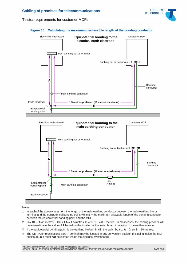
Cabling of premises for telecommunications
Telstra requirements for customer MDFs
TELSTRA CORPORATION LIMITED (ABN 33 051 775 556) | ISSUED 26/08/2013 ISSUE 2 – FINAL | TELSTRA UNRESTRICTED | DOCUMENT NO. 017153A08 | TELSTRA REQUIREMENTS FOR CUSTOMER MDFS
PAGE 28/45
Figure 16 Calculating the maximum permissible length of the bonding conductor
Main earthing bar or terminal
Electrical switchboard
Earth electrode
A
B
1.5 metres preferred (10 metres maximum)
bonding pointEquipotential
Equipotential bonding to theelectrical earth electrode
Main earthing conductor
Customer MDF
Earthing bar or backmount
Bondingconductor
Main earthing bar or terminal
Electrical switchboard
Earth electrode
A
B
Main earthing conductor
Bondingconductor
Equipotentialbonding point
Equipotential bonding to themain earthing conductor
1.5 metres preferred (10 metres maximum)
Customer MDF
Earthing bar or backmount
CET(Note 4)
Notes:
1. In each of the above cases, A = the length of the main earthing conductor between the main earthing bar or terminal and the equipotential bonding point, while B = the maximum allowable length of the bonding conductor
between the equipotential bonding point and the MDF.
2. B = 10 – A (in metres). Thus if A = 1.5 metres, B = 10-1.5 = 8.5 metres. In most cases, the cabling provider will have to estimate the value of A based on the location of the switchboard in relation to the earth electrode.
3. If the equipotential bonding point is the earthing bar/terminal in the switchboard, A = 0, so B = 10 metres.
4. The CET (Communications Earth Terminal) may be located in any convenient position (including inside the MDF enclosure) but must not be located inside the electrical switchboard.
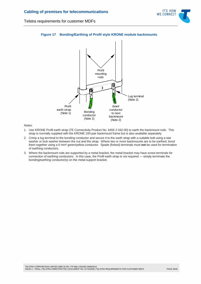
Cabling of premises for telecommunications
Telstra requirements for customer MDFs
TELSTRA CORPORATION LIMITED (ABN 33 051 775 556) | ISSUED 26/08/2013 ISSUE 2 – FINAL | TELSTRA UNRESTRICTED | DOCUMENT NO. 017153A08 | TELSTRA REQUIREMENTS FOR CUSTOMER MDFS
PAGE 29/45
Figure 17 Bonding/Earthing of Profil style KRONE module backmounts
conductor(Note 2)
Bonding to nextbackmount
conductor
(Note 2)
6mm²
mountingrods
Profil
earth strap(Note 1)
Profil
(Note 2)Lug terminal
Notes:
1. Use KRONE Profil earth strap (TE Connectivity Product No. 6455 2 042-00) to earth the backmount rods. This strap is normally supplied with the KRONE 100-pair backmount frame but is also available separately.
2. Crimp a lug terminal to the bonding conductor and secure it to the earth strap with a suitable bolt using a star washer or lock washer between the nut and the strap. Where two or more backmounts are to be earthed, bond them together using a 6 mm² green/yellow conductor. Spade (forked) terminals must not be used for termination
of earthing conductors.
3. Where the backmount rods are supported by a metal bracket, the metal bracket may have screw terminals for connection of earthing conductors. In this case, the Profil earth strap is not required — simply terminate the bonding/earthing conductor(s) on the metal support bracket.

Cabling of premises for telecommunications
Telstra requirements for customer MDFs
TELSTRA CORPORATION LIMITED (ABN 33 051 775 556) | ISSUED 26/08/2013 ISSUE 2 – FINAL | TELSTRA UNRESTRICTED | DOCUMENT NO. 017153A08 | TELSTRA REQUIREMENTS FOR CUSTOMER MDFS
PAGE 30/45
Figure 18 Bonding/Earthing of turret style KRONE module backmounts
Module mounting turret
Termination module
SIDE VIEW
28 mm(Note 2)
Arrestor magazine
Plastic cover (Note 3)
to next backmount(Note 1)
6mm² conductor
6 mm² lug terminal (Note 1)
Backmount
conductor(Note 1)
bonding
Notes:
1. Crimp a lug terminal to the bonding conductor and secure it to the backmount with a suitable bolt using a star washer or lock washer between the nut and the backmount. Where two or more backmounts are to be earthed, bond them together using a 6 mm² green/yellow conductor. Spade (forked) terminals must not be used for
termination of earthing conductors. The bonding conductor and other earthing conductors may be fastened on the inside or outside of the backmount, whichever is convenient.
2. MDFs are required to have a minimum clearance of 30 mm between the front face of the lead-in termination modules and the inside face of the door or cover of the MDF. This is to allow room for fitting of arrestor magazines.
3. The KRONE arrestor magazine is supplied with a clear plastic cover, which must be fitted to the installed magazine to prevent accidental human contact with the uninsulated arrestors.
6.16 Surge suppression
6.16.1 General
KRONE arrestor magazines are used to provide customer lightning protection (CLP) at customer MDFs
and are plugged into the front of KRONE Series 2 Disconnection modules. In designated high lightning
risk situations, the arrestor magazine will be fitted on the “A” side of the MDF by Telstra at Telstra’s cost.
In other circumstances, the lightning surge suppression must be installed on the “B” side of the MDF by
the cabling provider at the customer’s cost.
The standard Telstra KRONE arrestor magazine (TE Connectivity Product No. 6462 2 099-00) uses
500 V gas arrestors.
Note: 230 V KRONE arrestor magazines are available (TE Connectivity Product No. 6462 2 053-10) and may be used at a customer MDF. However, while these may provide slightly better surge protection for equipment, they do not significantly improve the level of end-user protection and the lower firing voltage increases the safety risk to the Telstra network under electrical power system fault conditions.

Cabling of premises for telecommunications
Telstra requirements for customer MDFs
TELSTRA CORPORATION LIMITED (ABN 33 051 775 556) | ISSUED 26/08/2013 ISSUE 2 – FINAL | TELSTRA UNRESTRICTED | DOCUMENT NO. 017153A08 | TELSTRA REQUIREMENTS FOR CUSTOMER MDFS
PAGE 31/45
Figure 19 KRONE arrestor magazine
Notes:
1. The standard arrestor magazine used by Telstra contains 500 V protectors and may be used to provide lightning surge suppression at either the customer MDF or other distributors on the customer’s side of the MDF. An arrestor magazine with 230 V protectors is also available but may only be used to provide surge suppression at a customer MDF.
2. The arrestor magazine is supplied with two Profil clips for insertion into the termination module to which the arrestor magazine is to be fitted and where a Profil backmount is used (see Figure 20). The kit also includes a clear plastic cover, which must be fitted to the installed magazine to prevent accidental human contact with the uninsulated protectors.
Figure 20 Fitting Profil earthing clips to a KRONE termination module
1 2 3 4 5 6 7 8 9 0
6.16.2 Backmount earthing
Ensure that the metallic backmount is connected to the bonding conductor as described in 6.15. There
are three different types of KRONE module backmount or mounting to be considered:
Profil type (i.e. mounting rods) — see Figure 17
turret style (i.e. U-shaped sheet metal with mounting tongues) — see Figure 18
10-pair MDF (the modules are moulded into the plastic base, but only the “A” side module has a
metal fitting that the arrestor magazine can connect to). The bonding conductor is connected to the
earth terminal, which in turn is bonded behind the MDF base to the metal turret at the lower end of
the “A” side module. See Figure 8 (page 18).
Note: A similar distribution box to the KRONE 10-pair MDF is available but must not be used as an MDF or for
installation of surge suppression because:
it does not have a metal turret for earthing of an arrestor magazine; and
the cover of this box is not deep enough to accommodate the arrestor magazine.
6.16.3 Running jumpers where an arrestor magazine is fitted
The arrestor magazine must be removed from the termination module to connect jumpers or test cords.
Unplug the arrestor magazine by pulling it straight out with even force at both ends of the magazine.
Don’t forget to plug the magazine back into the module after the jumpering or testing is done!
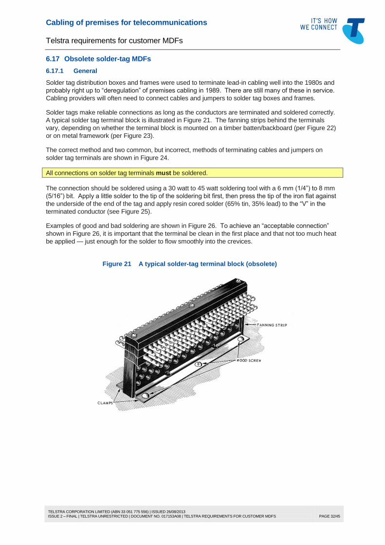
Cabling of premises for telecommunications
Telstra requirements for customer MDFs
TELSTRA CORPORATION LIMITED (ABN 33 051 775 556) | ISSUED 26/08/2013 ISSUE 2 – FINAL | TELSTRA UNRESTRICTED | DOCUMENT NO. 017153A08 | TELSTRA REQUIREMENTS FOR CUSTOMER MDFS
PAGE 32/45
6.17 Obsolete solder-tag MDFs
6.17.1 General
Solder tag distribution boxes and frames were used to terminate lead-in cabling well into the 1980s and
probably right up to “deregulation” of premises cabling in 1989. There are still many of these in service.
Cabling providers will often need to connect cables and jumpers to solder tag boxes and frames.
Solder tags make reliable connections as long as the conductors are terminated and soldered correctly.
A typical solder tag terminal block is illustrated in Figure 21. The fanning strips behind the terminals
vary, depending on whether the terminal block is mounted on a timber batten/backboard (per Figure 22)
or on metal framework (per Figure 23).
The correct method and two common, but incorrect, methods of terminating cables and jumpers on
solder tag terminals are shown in Figure 24.
All connections on solder tag terminals must be soldered.
The connection should be soldered using a 30 watt to 45 watt soldering tool with a 6 mm (1/4”) to 8 mm
(5/16”) bit. Apply a little solder to the tip of the soldering bit first, then press the tip of the iron flat against
the underside of the end of the tag and apply resin cored solder (65% tin, 35% lead) to the “V” in the
terminated conductor (see Figure 25).
Examples of good and bad soldering are shown in Figure 26. To achieve an “acceptable connection”
shown in Figure 26, it is important that the terminal be clean in the first place and that not too much heat
be applied — just enough for the solder to flow smoothly into the crevices.
Figure 21 A typical solder-tag terminal block (obsolete)
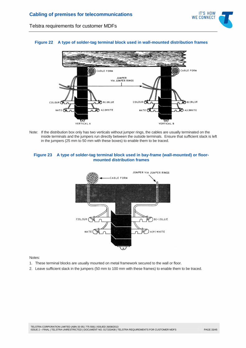
Cabling of premises for telecommunications
Telstra requirements for customer MDFs
TELSTRA CORPORATION LIMITED (ABN 33 051 775 556) | ISSUED 26/08/2013 ISSUE 2 – FINAL | TELSTRA UNRESTRICTED | DOCUMENT NO. 017153A08 | TELSTRA REQUIREMENTS FOR CUSTOMER MDFS
PAGE 33/45
Figure 22 A type of solder-tag terminal block used in wall-mounted distribution frames
Note: If the distribution box only has two verticals without jumper rings, the cables are usually terminated on the inside terminals and the jumpers run directly between the outside terminals. Ensure that sufficient slack is left in the jumpers (25 mm to 50 mm with these boxes) to enable them to be traced.
Figure 23 A type of solder-tag terminal block used in bay-frame (wall-mounted) or floor-
mounted distribution frames
Notes:
1. These terminal blocks are usually mounted on metal framework secured to the wall or floor.
2. Leave sufficient slack in the jumpers (50 mm to 100 mm with these frames) to enable them to be traced.

Cabling of premises for telecommunications
Telstra requirements for customer MDFs
TELSTRA CORPORATION LIMITED (ABN 33 051 775 556) | ISSUED 26/08/2013 ISSUE 2 – FINAL | TELSTRA UNRESTRICTED | DOCUMENT NO. 017153A08 | TELSTRA REQUIREMENTS FOR CUSTOMER MDFS
PAGE 34/45
Figure 24 Terminating a conductor on the solder-tag terminal
Insulatedconductor
Insulatedconductor
Incorrect!
Bareconductor
Insulatedconductor
Incorrect!
Breakoff here
Insulatedconductor
Correct!
Figure 25 Soldering terminated conductors
Notes:
1. Use a 30 watt to 45 watt soldering tool with a 6 mm (1/4”) to 8 mm (5/16”) bit and resin cored solder composed of 65% tin and 35% lead.
2. Apply a little solder to the tip of the soldering bit first, then press the tip of the iron flat against the underside of the end of the tag as shown above.
3. Apply solder to the “V” in the terminated conductor.
4. See Figure 26 for examples of good and bad soldering.

Cabling of premises for telecommunications
Telstra requirements for customer MDFs
TELSTRA CORPORATION LIMITED (ABN 33 051 775 556) | ISSUED 26/08/2013 ISSUE 2 – FINAL | TELSTRA UNRESTRICTED | DOCUMENT NO. 017153A08 | TELSTRA REQUIREMENTS FOR CUSTOMER MDFS
PAGE 35/45
Figure 26 Good and bad soldering
6.17.2 Link mounting frames
The solder tags in link mounting frames are different to the terminal blocks described above and a
different terminating method is used for the cable connections (see Figure 27). However, for jumpers,
use the same terminating method prescribed for other types of solder tags (as shown in Figure 24).
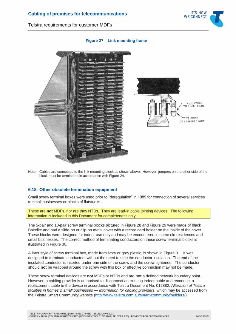
Cabling of premises for telecommunications
Telstra requirements for customer MDFs
TELSTRA CORPORATION LIMITED (ABN 33 051 775 556) | ISSUED 26/08/2013 ISSUE 2 – FINAL | TELSTRA UNRESTRICTED | DOCUMENT NO. 017153A08 | TELSTRA REQUIREMENTS FOR CUSTOMER MDFS
PAGE 36/45
Figure 27 Link mounting frame
Note: Cables are connected to the link mounting block as shown above. However, jumpers on the other side of the block must be terminated in accordance with Figure 24.
6.18 Other obsolete termination equipment
Small screw terminal boxes were used prior to “deregulation” in 1989 for connection of several services
to small businesses or blocks of flats/units.
These are not MDFs, nor are they NTDs. They are lead-in cable jointing devices. The following
information is included in this Document for completeness only.
The 5-pair and 10-pair screw terminal blocks pictured in Figure 28 and Figure 29 were made of black
Bakelite and had a slide-on or clip-on metal cover with a record card holder on the inside of the cover.
These blocks were designed for indoor use only and may be encountered in some old residences and
small businesses. The correct method of terminating conductors on these screw terminal blocks is
illustrated in Figure 30.
A later style of screw terminal box, made from ivory or grey plastic, is shown in Figure 31. It was
designed to terminate conductors without the need to strip the conductor insulation. The end of the
insulated conductor is inserted under one side of the screw and the screw tightened. The conductor
should not be wrapped around the screw with this box or effective connection may not be made.
These screw terminal devices are not MDFs or NTDs and are not a defined network boundary point.
However, a cabling provider is authorised to disconnect an existing indoor cable and reconnect a
replacement cable to the device in accordance with Telstra Document No. 012882, Alteration of Telstra
facilities in homes & small businesses — Information for cabling providers, which may be accessed from
the Telstra Smart Community website (http://www.telstra.com.au/smart-community/builders/).

Cabling of premises for telecommunications
Telstra requirements for customer MDFs
TELSTRA CORPORATION LIMITED (ABN 33 051 775 556) | ISSUED 26/08/2013 ISSUE 2 – FINAL | TELSTRA UNRESTRICTED | DOCUMENT NO. 017153A08 | TELSTRA REQUIREMENTS FOR CUSTOMER MDFS
PAGE 37/45
Where a faulty block/box needs to be replaced, the matter should be referred to Telstra. Telstra may
choose to replace the faulty block/box with a suitable joint or, if the customer/s is/are agreeable and the
position of the block/box meets the current requirements for the location of a customer MDF, replace it
with a small MDF, in which case it will then unambiguously become a network boundary point.
Figure 28 5-pair screw terminal block (obsolete)
This block is not an MDF or NTD
Note: This block was used to connect a 5-pair cable to two or more smaller cables (e.g. to connect two or more services to a small business or to connect services to two or more shops, units or flats). Only one conductor should be terminated under each screw as shown in Figure 30.
Figure 29 10-pair screw terminal block (obsolete)
This block is not an MDF or NTD
Note: This block was used to connect a 6-pair or 10-pair cable to two or more smaller cables (e.g. to connect two or more services to a small business or to connect services to two or more shops, units or flats). Only one conductor should be terminated under each screw as shown in Figure 30.

Cabling of premises for telecommunications
Telstra requirements for customer MDFs
TELSTRA CORPORATION LIMITED (ABN 33 051 775 556) | ISSUED 26/08/2013 ISSUE 2 – FINAL | TELSTRA UNRESTRICTED | DOCUMENT NO. 017153A08 | TELSTRA REQUIREMENTS FOR CUSTOMER MDFS
PAGE 38/45
Figure 30 Terminating conductors on screw terminal blocks
Note: Only one conductor should be terminated under each screw. If more than one conductor needs to be terminated under the screw, twist the bare conductors together before wrapping them around the screw and lightly tighten the screw (over-tightening the screw may sever one or more of the twisted conductors).
Figure 31 Insulation-crushing screw terminal box (obsolete)
an MDF or NTDThis box is not
Notes:
1. This box was used to interconnect several cables (e.g. to connect two or more services to a small business or to connect services to two or more shops, units or flats).
2. With this box, the insulated conductor must be inserted under one side of the screw and the screw tightened. Do not wrap the conductor around the screw or proper connection may not be made. Only one conductor should be
connected to each screw.

Cabling of premises for telecommunications
Telstra requirements for customer MDFs
TELSTRA CORPORATION LIMITED (ABN 33 051 775 556) | ISSUED 26/08/2013 ISSUE 2 – FINAL | TELSTRA UNRESTRICTED | DOCUMENT NO. 017153A08 | TELSTRA REQUIREMENTS FOR CUSTOMER MDFS
PAGE 39/45
6.19 Contacting Telstra
6.19.1 New MDF
Where it is necessary to contact Telstra for advice about the installation (e.g. location) of a new MDF or
to get the Telstra lead-in cable terminated on the MDF, please call the appropriate number listed below
and follow the procedure listed.
Home .................................................................................................................................
Business ............................................................................................................................
To the automated voice greeting, respond “connections”, then “fixed line phone”,
and then your telephone number or “I don’t have one”, as applicable.
Inform the Telstra consultant that you need to get Telstra’s lead-in cabling
terminated on the customer MDF.
State the address to which the enquiry is related and, when requested, your name
and contact number. If you were previously given a job number when arranging
lead-in pre-provisioning or an order number when requesting a new service, quote
this number.
If the Telstra consultant suggests that you may get any registered cabler to do the
work, clarify that it is network cabling work that is outside the scope of work that
registered cablers are permitted to do.
For new buildings, the lead-in cabling is terminated on the MDF at Telstra’s cost
(this includes supply of the lead-in termination modules). If the work is required
due to building or MDF alterations that are not associated with the connection of
additional new Telstra services, charges will apply for the work, payable either to
Telstra (if Telstra does the work) or directly to the Telstra contractor (if a Telstra
contractor does the work).
13 2200
13 2000
6.19.2 MDF alterations
For relocation of an existing MDF or associated lead-in cabling (e.g. due to building renovations or land
redevelopment), please call the number listed below and select the appropriate option.
Home or Business .............................................................................................................
Whether or not you believe any digging will be necessary, first contact the Dial
Before You Dig (DBYD) “free call service”, by telephoning 1100 or by visiting the
DBYD website at www.1100.com.au for information about any underground
services that may be in the vicinity.
Once you have received the plans, call the above 1800 number.
You will receive a brief automated voice greeting and then you will be switched
through to the Telstra Network Integrity Team with which you may discuss your
requirements.
The labour rate and other charges that apply for the alterations required are set out
in Telstra’s “Our Customer Terms” available online at
http://www.telstra.com.au/customer-terms/.
1800 810 443

Cabling of premises for telecommunications
Telstra requirements for customer MDFs
TELSTRA CORPORATION LIMITED (ABN 33 051 775 556) | ISSUED 26/08/2013 ISSUE 2 – FINAL | TELSTRA UNRESTRICTED | DOCUMENT NO. 017153A08 | TELSTRA REQUIREMENTS FOR CUSTOMER MDFS
PAGE 40/45
7 DEFINITIONS
Term Definition
A2A “Authorisation to Alter” (Telstra Document No. 012882)
ACMA Australian Communications and Media Authority (formerly AUSTEL, then
ACA) — the telecommunications industry regulator responsible for
technical regulation (e.g. governance of compliance labelling, cabling
provider registration, mandatory technical standards for customer
equipment, and wiring rules)
ACMA-compliant Complies with technical standards made by the ACMA, specifically
Australian Standard AS/CA S008, Requirements for customer cabling
products, and its predecessors
AS Australian Standard
AS/CA (Australian Standard/
Communications Alliance)
An Australian standard developed and produced by Communications
Alliance (formerly ACIF)
AS/NZS (Australian/New Zealand
Standard)
A joint Australian/New Zealand Standard prepared by representatives from
each country and which includes requirements common to each country
bonding See “equipotential bonding”
builder A person charged with the construction or renovation of any building
building A substantial construction intended to protect persons, animals, vehicles,
machinery, tools or equipment from the weather
building entry point The point on a building where telecommunications cabling enters the
building
CA Communications Alliance
cabler See “cabling provider”
cabling Cable or cables and any associated works or parts such as pits, poles,
conduits, trays, connecting devices, jumpers, etc.
cabling provider A person registered as a cabling provider under the Cabling Provider
Rules
Cabling Provider Rules The Telecommunications Cabling Provider Rules 2000
coaxial cable A dual conductor cable in which a centre conductor is surrounded by, but
does not contact, a concentric, cylindrical outer conductor
conduit A tube or pipe that physically accommodates cables
cross-connection A method of providing for flexible interconnection of cables or cable
elements (e.g. pairs) by means of jumpers or patch cords

Cabling of premises for telecommunications
Telstra requirements for customer MDFs
TELSTRA CORPORATION LIMITED (ABN 33 051 775 556) | ISSUED 26/08/2013 ISSUE 2 – FINAL | TELSTRA UNRESTRICTED | DOCUMENT NO. 017153A08 | TELSTRA REQUIREMENTS FOR CUSTOMER MDFS
PAGE 41/45
Term Definition
customer A person who subscribes to (pays for) the supply of a telecommunications
network service or an end-user of that service
customer cabling Any cabling connected on the customer’s side of the network boundary
customer equipment Any equipment connected on the customer’s side of the network boundary
distributor A collection of components used to terminate cables and which provides
facilities for cross-connection by means of jumpers or patch cords
earth An electrical connection to the mass of earth. This can be made by driving
or burying a metal electrode in the ground but, within customer premises,
is usually – and should be – made via a connection to the earthing bar or
terminal of the electrical switchboard or to the earth electrode of the
electrical earthing system. Earth may also be described as “ground”.
earthing The act of connecting equipment or cabling to an earth reference such as
to the electrical earthing system of the electrical installation or an earth
electrode. Earthing may also be described as “grounding”.
equipotential bonding Bonding (connecting) two or more earthing systems or earthed parts
together to ensure that they are at approximately “equal potential”
FDP Final Distribution Point — a cable distribution device used as the last
distribution point in a distributed cabling system
fibre/fiber See “optical fibre”
first socket That socket within a building that terminates Telstra’s lead-in cable. There
may be more than one first socket within a building (e.g. multiple lines).
The first socket is a defined network boundary point.
first TO The telecommunications outlet (TO) that contains the first socket
home networking Cabling within a home that is capable of being used to link (“network”)
several personal computers — see “structured cabling”
HV High Voltage — a voltage exceeding 1000 V AC or 1500 V DC
indoor Installed inside a building
ISO/IEC International Standardisation Organisation/International Electrotechnical
Commission — used to prefix a standard or other document developed
jointly by both organisations
jumper A cable unit or cable element without connectors (e.g. a pair of wires) used
to make a cross-connection within a distributor
KRONE KRONE Australia (manufactured by TE Connectivity) — the brand of
Telstra’s standard lead-in termination modules for customer MDFs

Cabling of premises for telecommunications
Telstra requirements for customer MDFs
TELSTRA CORPORATION LIMITED (ABN 33 051 775 556) | ISSUED 26/08/2013 ISSUE 2 – FINAL | TELSTRA UNRESTRICTED | DOCUMENT NO. 017153A08 | TELSTRA REQUIREMENTS FOR CUSTOMER MDFS
PAGE 42/45
Term Definition
lead-in cabling A carrier’s (e.g. Telstra’s) cabling from the last distribution point (typically in
the street) and the network boundary in the customer's premises
LV Low Voltage — a voltage exceeding 42.4 V peak (about 30 V AC r.m.s. for
a sine wave) or 60 V DC but not exceeding 1000 V AC or 1500 V DC
m metre or metres
Main Distribution Frame See “MDF”
max. maximum
MDF Main Distribution Frame — a distributor that provides an electrical
termination point for a carrier’s (e.g. Telstra’s) lead-in cabling. An MDF is
a defined network boundary point.
min. minimum
mm millimetre/s — one millimetre is one thousandth of a metre
network boundary (point) The point that is deemed by legislation to be the boundary of a carrier’s
telecommunications network. This is usually an MDF, an NTD or a socket.
NTD Network Termination Device — a device provided by a carrier to establish
a demarcation point between the carrier’s telecommunications network
and customer cabling or customer equipment. The NTD will be
permanently marked at manufacture with the words “Network Termination
Device” or the letters “NTD”. An NTD is a defined network boundary point.
NTD See “Network Termination Device”
optical fibre A fine, flexible, transparent fibre made of pure glass (silica) designed to
convey light between two points. The American spelling, “fiber”, is often
encountered but there is no actual difference between “fibre” and “fiber”.
outdoor Installed outside a building, including on the external surface of a building
or other structure
patch cord A flexible cord terminated with plugs to make a cross-connection between
sockets within a patch panel or between a socket and equipment
patch panel An array of sockets that may be cross-connected by means of patch cords
premises An area of land that contains one or more buildings. In this Document,
“premises” refers to the land and any building or structure located on that
land. The description “building” is used in reference to any building within
the premises.
registered cabler / cabling provider A person who is registered in accordance with regulatory requirements to
install or repair customer cabling

Cabling of premises for telecommunications
Telstra requirements for customer MDFs
TELSTRA CORPORATION LIMITED (ABN 33 051 775 556) | ISSUED 26/08/2013 ISSUE 2 – FINAL | TELSTRA UNRESTRICTED | DOCUMENT NO. 017153A08 | TELSTRA REQUIREMENTS FOR CUSTOMER MDFS
PAGE 43/45
Term Definition
rural An area in which the properties have frontages greater than an average of
60 m, lot sizes generally larger than 1000 m², and there is usually no curb
and channel and no street lighting. The telecommunications network
construction is usually characterised by long cable routes with direct-
buried cables.
service provider A supplier of carriage services (e.g. an internet or pay TV connection using
a carrier’s network) or content services (e.g. pay TV programs or an
internet website)
socket Often also described as a “jack”, a socket is a connecting device designed
to accept a mating plug
structured cabling A term used to describe a cabling system having a structure that enables it
to be used for various purposes including a local area network (LAN) and
telephony — also called “generic cabling”
surge suppression A device or technique used to limit the rise in voltage between two or more
parts of a cabling system or within equipment, which may be caused by a
lightning discharge or a surge in the power supply system
telecommunications network A system, or series of systems, that is operated by a carrier or carriage
service provider for carrying communications to, from or between
customers by means of guided and/or unguided electromagnetic energy
telecommunications outlet (TO) A fixed connecting device to which an end-user may connect customer
equipment to telecommunications cabling. A telecommunications outlet
includes the socket(s) and associated mounting hardware (e.g. wall plate)
Telstra Telstra, its employees or contractors
TO ( or TOs) See “telecommunications outlet”
trunking A tray or trough system with removable covers along its length that is used
for housing and protecting cables — sometimes referred to as “ducting”
urban An area in which the properties have frontages less than an average of
60 m, lot sizes generally smaller than 1000 m², and the roads usually have
curb and channel and street lighting. The telecommunications network
cables are usually installed in conduit.
V Volt/s
V AC or V a.c. Volt/s alternating current
V DC or V d.c. Volt/s direct current
wiring rules For telecommunications cabling, this means Australian Standard AS/CA
S009 or its replacement. For electrical cabling, this means Australian/New
Zealand Standard AS/NZS 3000.

Cabling of premises for telecommunications
Telstra requirements for customer MDFs
TELSTRA CORPORATION LIMITED (ABN 33 051 775 556) | ISSUED 26/08/2013 ISSUE 2 – FINAL | TELSTRA UNRESTRICTED | DOCUMENT NO. 017153A08 | TELSTRA REQUIREMENTS FOR CUSTOMER MDFS
PAGE 44/45
8 REFERENCES
Document number Title
012688 Telstra Network Termination Device (NTD) — Information for cabling
providers
012882 Alteration of Telstra facilities in homes & small businesses — Information
for cabling providers
AS/CA S008 Requirements for customer cabling products
AS/CA S009 Installation requirements for customer cabling (Wiring rules)
AS 3835.1 Earth potential rise — Protection of telecommunications network users,
personnel and plant — Code of practice
AS 60529 Degrees of protection provided by enclosures (IP Code)
AS/NZS ISO/IEC 15018 Information technology — Generic cabling for homes
HB 252 Communications Cabling Manual Module 3: Residential communications
cabling handbook
CA C559 Part 1 Industry Code: Unconditioned Local Loop Service (ULLS) Network
Deployment Part 1 — ULLS Performance Requirements

Cabling of premises for telecommunications
Telstra requirements for customer MDFs
TELSTRA CORPORATION LIMITED (ABN 33 051 775 556) | ISSUED 26/08/2013 ISSUE 2 – FINAL | TELSTRA UNRESTRICTED | DOCUMENT NO. 017153A08 | TELSTRA REQUIREMENTS FOR CUSTOMER MDFS
PAGE 45/45
9 DOCUMENT CONTROL SHEET
Issue number Issue date Details on the change
1 22 June 2009
2 26/08/2013 General update