cad & component drawing
DESCRIPTION
AERONAUTICAL ENGINEERING R2013 - ANNA UNIVERSITYTRANSCRIPT
DESIGN AND DRAFTING OF RIVETED JOINTS
EX. No. 1
DATE:
AIM:
To perform the design calculation of the riveted joints and draft it with necessary
dimensions using 2D drafting software.
RIVETED JOINTS:
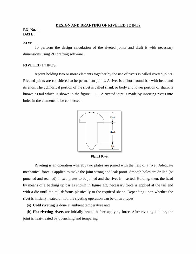
A joint holding two or more elements together by the use of rivets is called riveted joints.
Riveted joints are considered to be permanent joints. A rivet is a short round bar with head and
its ends. The cylindrical portion of the rivet is called shank or body and lower portion of shank is
known as tail which is shown in the figure – 1.1. A riveted joint is made by inserting rivets into
holes in the elements to be connected.
Fig.1.1 Rivet
Riveting is an operation whereby two plates are joined with the help of a rivet. Adequate
mechanical force is applied to make the joint strong and leak proof. Smooth holes are drilled (or
punched and reamed) in two plates to be joined and the rivet is inserted. Holding, then, the head
by means of a backing up bar as shown in figure 1.2, necessary force is applied at the tail end
with a die until the tail deforms plastically to the required shape. Depending upon whether the
rivet is initially heated or not, the riveting operation can be of two types:
(a) Cold riveting is done at ambient temperature and
(b) Hot riveting rivets are initially heated before applying force. After riveting is done, the
joint is heat-treated by quenching and tempering.

Fig. 1.2 Riveting Operation
TYPES OF RIVETED JOINTS:
Riveted joints are mainly of two types
Lap joints
Butt joints
Lap Joints
The plates that are to be joined are brought face to face such that an overlap exists, as
shown in figure 1.3. Rivets are inserted on the overlapping portion. Single or multiple rows of
rivets are used to give strength to the joint. Depending upon the number of rows the riveted joints
may be classified as single riveted lap joint, double or triple riveted lap joint etc. When multiple
joints are used, the arrangement of rivets between two neighboring rows may be of two kinds. In
chain riveting the adjacent rows have rivets in the same transverse line. In zig-zag riveting, on
the other hand, the adjacent rows of rivets are staggered. Different types of lap joints are
sketched in figure 1.3(a) – 1.3(c).
Fig.1.3 Lap Joint
Fig.1.3 (a): Single rivet lap joint
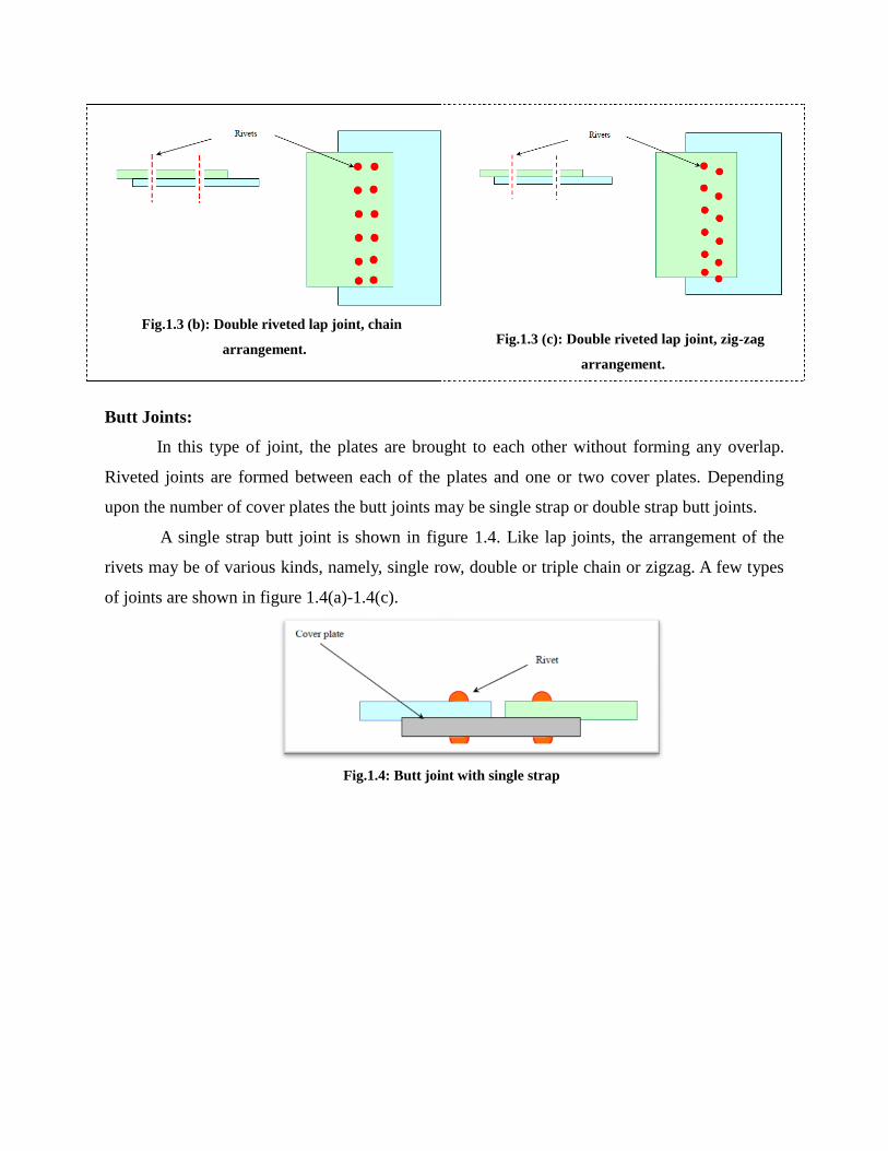
Fig.1.3 (b): Double riveted lap joint, chain
arrangement.
Fig.1.3 (c): Double riveted lap joint, zig-zag
arrangement.
Butt Joints:
In this type of joint, the plates are brought to each other without forming any overlap.
Riveted joints are formed between each of the plates and one or two cover plates. Depending
upon the number of cover plates the butt joints may be single strap or double strap butt joints.
A single strap butt joint is shown in figure 1.4. Like lap joints, the arrangement of the
rivets may be of various kinds, namely, single row, double or triple chain or zigzag. A few types
of joints are shown in figure 1.4(a)-1.4(c).
Fig.1.4: Butt joint with single strap
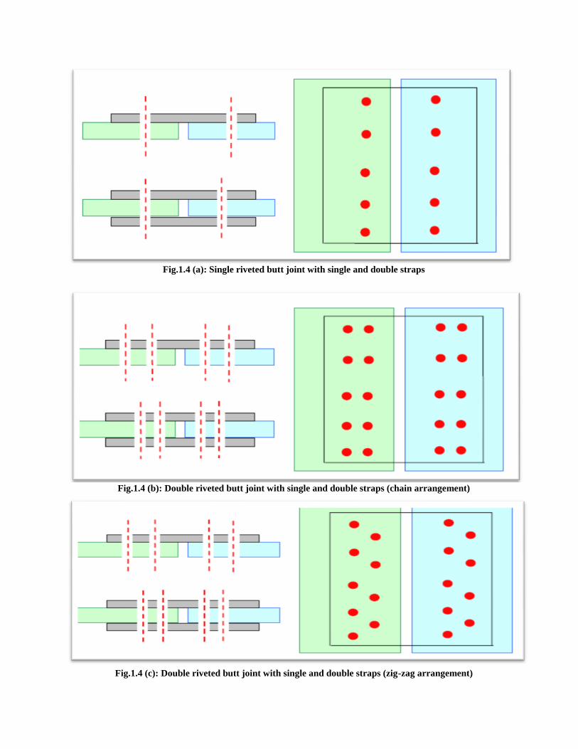
Fig.1.4 (a): Single riveted butt joint with single and double straps
Fig.1.4 (b): Double riveted butt joint with single and double straps (chain arrangement)
Fig.1.4 (c): Double riveted butt joint with single and double straps (zig-zag arrangement)
IMPORTANT TERMS USED IN RIVETED JOINTS:
Few parameters, which are required to specify arrangement of rivets in a riveted joint are
as follows
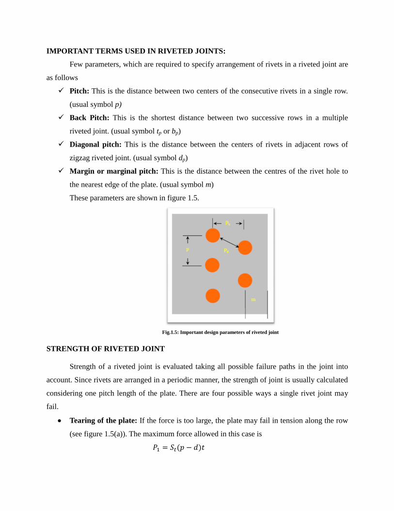
Pitch: This is the distance between two centers of the consecutive rivets in a single row.
(usual symbol p)
Back Pitch: This is the shortest distance between two successive rows in a multiple
riveted joint. (usual symbol tp or bp)
Diagonal pitch: This is the distance between the centers of rivets in adjacent rows of
zigzag riveted joint. (usual symbol dp)
Margin or marginal pitch: This is the distance between the centres of the rivet hole to
the nearest edge of the plate. (usual symbol m)
These parameters are shown in figure 1.5.
Fig.1.5: Important design parameters of riveted joint
STRENGTH OF RIVETED JOINT
Strength of a riveted joint is evaluated taking all possible failure paths in the joint into
account. Since rivets are arranged in a periodic manner, the strength of joint is usually calculated
considering one pitch length of the plate. There are four possible ways a single rivet joint may
fail.
Tearing of the plate: If the force is too large, the plate may fail in tension along the row
(see figure 1.5(a)). The maximum force allowed in this case is
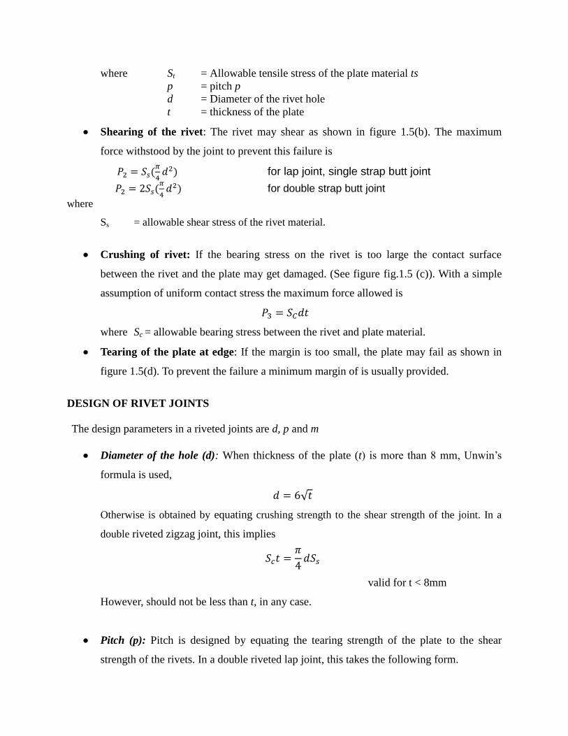
where St = Allowable tensile stress of the plate material ts
p = pitch p
d = Diameter of the rivet hole
t = thickness of the plate
Shearing of the rivet: The rivet may shear as shown in figure 1.5(b). The maximum
force withstood by the joint to prevent this failure is
for lap joint, single strap butt joint
for double strap butt joint
where
Ss = allowable shear stress of the rivet material.
Crushing of rivet: If the bearing stress on the rivet is too large the contact surface
between the rivet and the plate may get damaged. (See figure fig.1.5 (c)). With a simple
assumption of uniform contact stress the maximum force allowed is
where Sc = allowable bearing stress between the rivet and plate material.
Tearing of the plate at edge: If the margin is too small, the plate may fail as shown in
figure 1.5(d). To prevent the failure a minimum margin of is usually provided.
DESIGN OF RIVET JOINTS
The design parameters in a riveted joints are d, p and m
Diameter of the hole (d): When thickness of the plate (t) is more than 8 mm, Unwin’s
formula is used,
Otherwise is obtained by equating crushing strength to the shear strength of the joint. In a
double riveted zigzag joint, this implies
valid for t < 8mm
However, should not be less than t, in any case.
Pitch (p): Pitch is designed by equating the tearing strength of the plate to the shear
strength of the rivets. In a double riveted lap joint, this takes the following form.

But p ≥ 2d in order to accommodate heads of the rivets.
Margin (m): . m= 1.5d
Problem Definition:
DESIGN CALCULATIONS:

PROCEDURE:
1) Study the problem definition which is given.
2) Based on the problem definition design the rivet using the formulas given.
3) Using the values which have been found using the formulas draft the rivet model in the
A3 sheet.
RESULT:
Thus the required riveted joint is designed and drafted as per the designed dimensions.

DESIGN AND DRAFTING OF WELDED JOINTS
EX. No. 2
DATE:
AIM:
To perform the design calculation of the welded joints and draft it with necessary
dimensions using 2D drafting software.
WELDED JOINTS – AN INTRODUCTION:
A welded joint is a permanent joint which is obtained by the fusion of the edges of the
two parts to be joined together, with or without the application of pressure and a filler material.
The heat required for the fusion of the material may be obtained by burning of gas (in case of gas
welding) or by an electric arc (in case of electric arc welding). The latter method is extensively
used because of greater speed of welding.
Welding is extensively used in fabrication as an alternative method for casting or forging
and as a replacement for bolted and riveted joints. It is also used as a repair medium e.g. to
reunite metal at a crack, to build up a small part that has broken off such as gear tooth or to repair
a worn surface such as a bearing surface.
ADVANTAGES AND DISADVANTAGES OF WELDED JOINTS OVER RIVETED
JOINTS:
Following are the advantages and disadvantages of welded joints over riveted joints.
Advantages
The welded structures are usually lighter than riveted structures. This is due to the reason,
that in welding, gussets or other connecting components are not used.
The welded joints provide maximum efficiency (may be 100%) which is not possible in
case of riveted joints.
Alterations and additions can be easily made in the existing structures.
As the welded structure is smooth in appearance, therefore it looks pleasing.
In welded connections, the tension members are not weakened as in the case of riveted
joints.
A welded joint has a great strength. Often a welded joint has the strength of the parent
metal itself.
Sometimes, the members are of such a shape (i.e. circular steel pipes) that they afford
difficulty for riveting. But they can be easily welded.
The welding provides very rigid joints. This is in line with the modern trend of providing
rigid frames.
It is possible to weld any part of a structure at any point. But riveting requires enough
clearance.
The process of welding takes less time than the riveting.
Disadvantages
Since there is an uneven heating and cooling during fabrication, therefore the members
may get distorted or additional stresses may develop.
It requires a highly skilled labour and supervision.
Since no provision is kept for expansion and contraction in the frame, therefore there is a
possibility of cracks developing in it.
The inspection of welding work is more difficult than riveting work.
TYPES OF WELDED JOINTS:
Following two types of welded joints are important from the subject point of view:
Lap joint or fillet joint, and
Butt joint.
Lap Joint:
The lap joint or the fillet joint is obtained by overlapping the plates and then welding the
edges of the plates. The cross-section of the fillet is approximately triangular. The fillet joints
may be
Single transverse fillet,
Double transverse fillet, and
Parallel fillet joints.
The fillet joints are shown in Fig.2.1. A single transverse fillet joint has the disadvantage
that the edge of the plate which is not welded can buckle or warp out of shape.
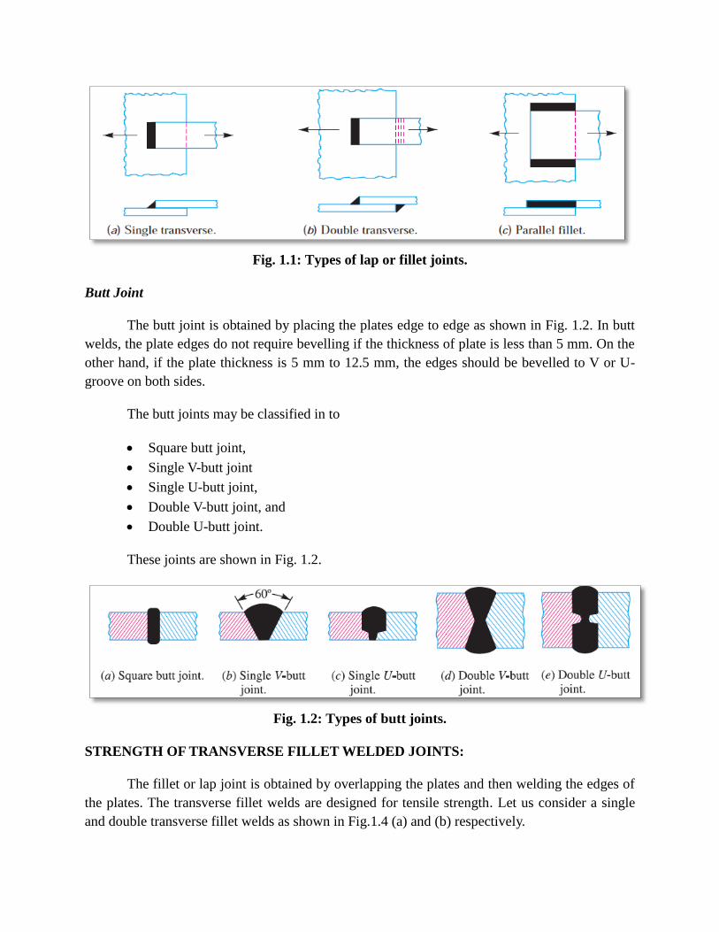
Fig. 1.1: Types of lap or fillet joints.
Butt Joint
The butt joint is obtained by placing the plates edge to edge as shown in Fig. 1.2. In butt
welds, the plate edges do not require bevelling if the thickness of plate is less than 5 mm. On the
other hand, if the plate thickness is 5 mm to 12.5 mm, the edges should be bevelled to V or U-
groove on both sides.
The butt joints may be classified in to
Square butt joint,
Single V-butt joint
Single U-butt joint,
Double V-butt joint, and
Double U-butt joint.
These joints are shown in Fig. 1.2.
Fig. 1.2: Types of butt joints.
STRENGTH OF TRANSVERSE FILLET WELDED JOINTS:
The fillet or lap joint is obtained by overlapping the plates and then welding the edges of
the plates. The transverse fillet welds are designed for tensile strength. Let us consider a single
and double transverse fillet welds as shown in Fig.1.4 (a) and (b) respectively.
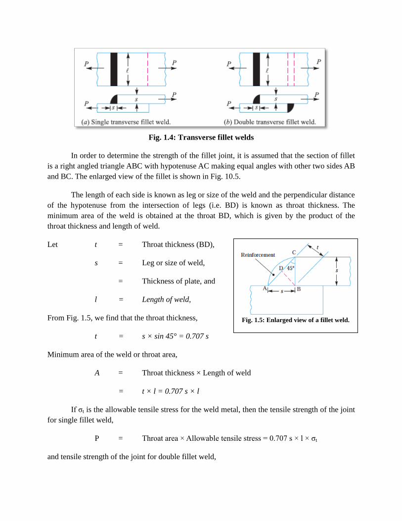
Fig. 1.4: Transverse fillet welds
In order to determine the strength of the fillet joint, it is assumed that the section of fillet
is a right angled triangle ABC with hypotenuse AC making equal angles with other two sides AB
and BC. The enlarged view of the fillet is shown in Fig. 10.5.
The length of each side is known as leg or size of the weld and the perpendicular distance
of the hypotenuse from the intersection of legs (i.e. BD) is known as throat thickness. The
minimum area of the weld is obtained at the throat BD, which is given by the product of the
throat thickness and length of weld.
Let t = Throat thickness (BD),
s = Leg or size of weld,
= Thickness of plate, and
l = Length of weld,
From Fig. 1.5, we find that the throat thickness,
t = s × sin 45° = 0.707 s
Minimum area of the weld or throat area,
A = Throat thickness × Length of weld
= t × l = 0.707 s × l
If σt is the allowable tensile stress for the weld metal, then the tensile strength of the joint
for single fillet weld,
P = Throat area × Allowable tensile stress = 0.707 s × l × σt
and tensile strength of the joint for double fillet weld,
Fig. 1.5: Enlarged view of a fillet weld.
P = 2 × 0.707 s × l × σt = 1.414 s × l × σt
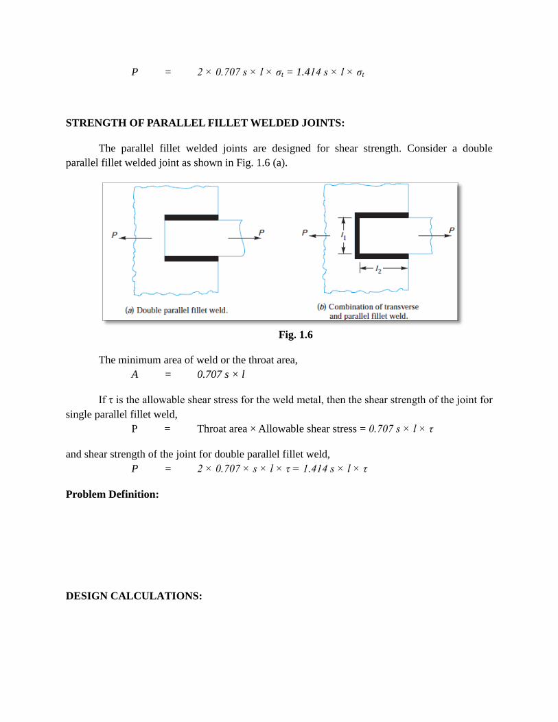
STRENGTH OF PARALLEL FILLET WELDED JOINTS:
The parallel fillet welded joints are designed for shear strength. Consider a double
parallel fillet welded joint as shown in Fig. 1.6 (a).
Fig. 1.6
The minimum area of weld or the throat area,
A = 0.707 s × l
If τ is the allowable shear stress for the weld metal, then the shear strength of the joint for
single parallel fillet weld,
P = Throat area × Allowable shear stress = 0.707 s × l × τ
and shear strength of the joint for double parallel fillet weld,
P = 2 × 0.707 × s × l × τ = 1.414 s × l × τ
Problem Definition:
DESIGN CALCULATIONS:

PROCEDURE:
1) Study the problem definition which is given.
2) Based on the problem definition design the weld joint using the formulas given.
3) Using the values which have been found using the formulas draft the weld joint model in
the A3 sheet.
RESULT:
Thus the required welded joint is designed and drafted as per the designed parameters.
DESIGN AND DRAFTING OF CONTROL COMPONENTS OF CAM
EX. No. 3
DATE:
AIM:
To perform the design calculation of the cam mechanism and draft it with necessary
dimensions using 2D drafting software.
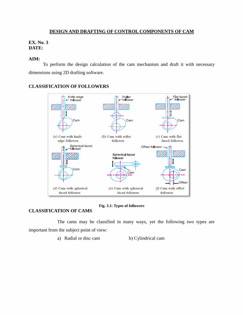
CLASSIFICATION OF FOLLOWERS
Fig. 3.1: Types of followers
CLASSIFICATION OF CAMS
The cams may be classified in many ways, yet the following two types are
important from the subject point of view:
a) Radial or disc cam b) Cylindrical cam

Fig.3.2: Cylindrical CAM
NOMENCLATURE OF RADIAL CAMS:
Fig. 3.3 shows a radial cam with reciprocating roller follower. The following terms are
important in order to draw the cam profile.
1. Base circle. It is the smallest circle that can be drawn to the cam profile.
2. Trace point. It is a reference point on the follower and is used to generate the pitch curve.
In case of knife edge follower, the knife edge represents the trace point and the pitch curve
corresponds to the cam profile. In a roller follower, the centre of the roller represents the trace
point.
Fig. 3.3: Terms used in radial cams
3. Pressure angle. It is the angle between the direction of the follower motion and a normal to
the pitch curve. This angle is very important in designing a cam profile. If the pressure angle is
too large, a reciprocating follower will jam in its bearings.
4. Pitch point. It is a point on the pitch curve having the maximum pressure angle.
5. Pitch circle. It is a circle drawn from the centre of the cam through the pitch points.
6. Pitch curve. It is the curve generated by the trace point as the follower moves relative to the
cam. For a knife edge follower, the pitch curve and the cam profile are same whereas for a roller
follower, they are separated by the radius of the roller.
7. Prime circle. It is the smallest circle that can be drawn from the centre of the cam and tangent
to the pitch curve. For a knife edge and a flat face follower, the prime circle and the base circle
are identical. For a roller follower, the prime circle is larger than the base circle by the radius of
the roller.
8. Lift or stroke. It is the maximum travel of the follower from its lowest position to the topmost
position.
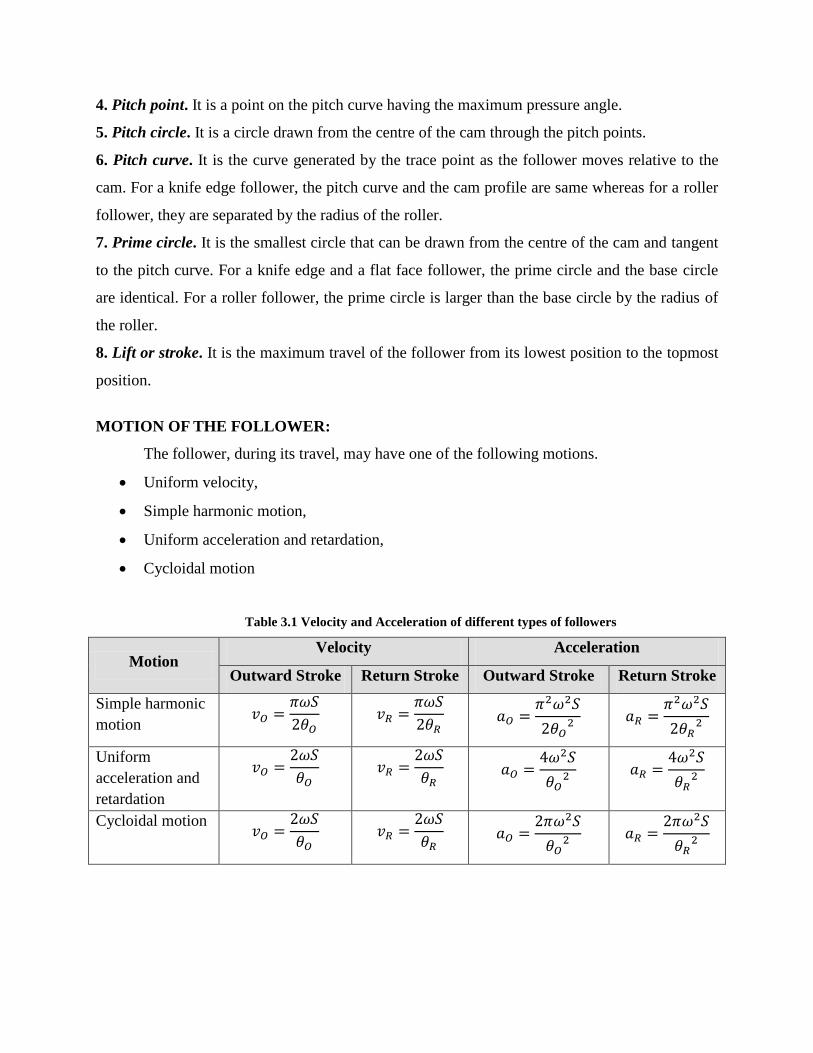
MOTION OF THE FOLLOWER:
The follower, during its travel, may have one of the following motions.
Uniform velocity,
Simple harmonic motion,
Uniform acceleration and retardation,
Cycloidal motion
Table 3.1 Velocity and Acceleration of different types of followers
Motion Velocity Acceleration
Outward Stroke Return Stroke Outward Stroke Return Stroke
Simple harmonic
motion
Uniform
acceleration and
retardation
Cycloidal motion

Problem Definition:
DESIGN CALCULATIONS:

PROCEDURE:
1) Study the problem definition which is given.
2) Based on the problem definition design the cam using the formulas given.
3) Using the values which have been found using the formulas draft the cam model in the
A3 sheet.
RESULT:
Thus the required cam is designed and drafted as per the designed parameters.
DESIGN AND DRAFTING CONTROL COMPONENTS BELL CRANK
EX. No. 4
DATE:
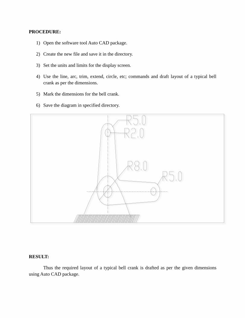
AIM:
To draft the layout of a typical bell crank with necessary dimensions using 2D drafting
software.
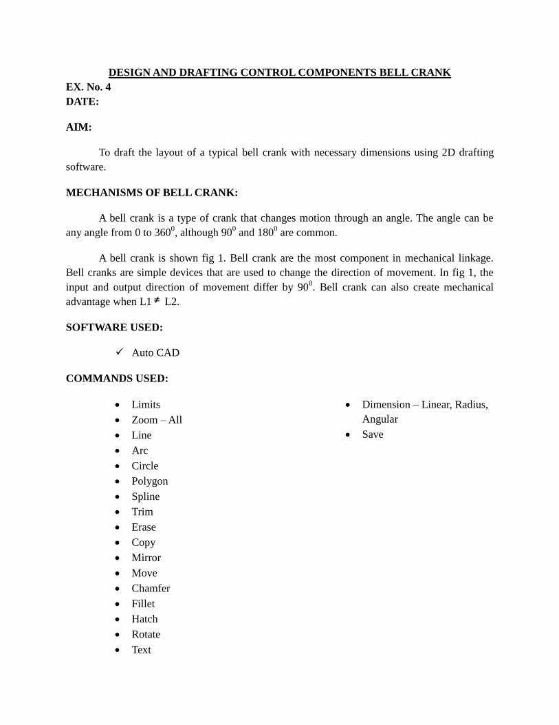
MECHANISMS OF BELL CRANK:
A bell crank is a type of crank that changes motion through an angle. The angle can be
any angle from 0 to 3600, although 90
0 and 180
0 are common.
A bell crank is shown fig 1. Bell crank are the most component in mechanical linkage.
Bell cranks are simple devices that are used to change the direction of movement. In fig 1, the
input and output direction of movement differ by 900. Bell crank can also create mechanical
advantage when L1 L2.
SOFTWARE USED:
Auto CAD
COMMANDS USED:
Limits
Zoom – All
Line
Arc
Circle
Polygon
Spline
Trim
Erase
Copy
Mirror
Move
Chamfer
Fillet
Hatch
Rotate
Text
Dimension – Linear, Radius,
Angular
Save
PROCEDURE:
1) Open the software tool Auto CAD package.
2) Create the new file and save it in the directory.
3) Set the units and limits for the display screen.
4) Use the line, arc, trim, extend, circle, etc; commands and draft layout of a typical bell
crank as per the dimensions.
5) Mark the dimensions for the bell crank.
6) Save the diagram in specified directory.
RESULT:
Thus the required layout of a typical bell crank is drafted as per the given dimensions
using Auto CAD package.
DESIGN AND DRAFTING CONTROL COMPONENTS GEAR
EX. No. 5
DATE:
AIM:
To perform the design calculations of the spur gear drive and draft it with necessary
dimensions using 2D drafting software.
INTRODUCTION TO GEARS:
Gears are toothed members which transmit power / motion between two shafts by
meshing without any slip. Hence, gear drives are also called positive drives. In any pair of gears,
the smaller one is called pinion and the larger one is called gear immaterial of which is driving
the other.
When pinion is the driver, it results in step down drive in which the output speed
decreases and the torque increases. On the other hand, when the gear is the driver, it results in
step up drive in which the output speed increases and the torque decreases.
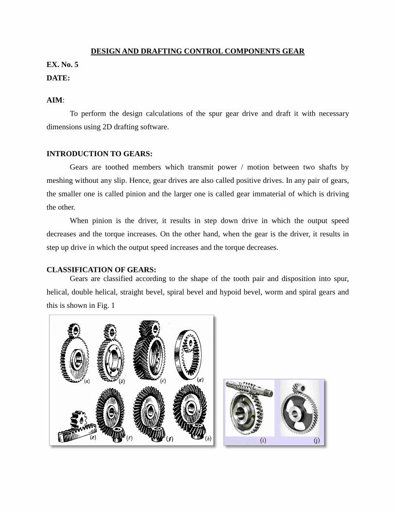
CLASSIFICATION OF GEARS:
Gears are classified according to the shape of the tooth pair and disposition into spur,
helical, double helical, straight bevel, spiral bevel and hypoid bevel, worm and spiral gears and
this is shown in Fig. 1

Fig. 1 (a) Spur gear, (b) helical gear, (c) Double helical gear or herringbone gear, (d)
Internal gear , (e) Rack and pinion, (f) Straight bevel gear, (g) Spiral bevel gear, (h) Hypoid
bevel gear , (i) worm gear and (j) Spiral gear
NOMENCLATURE OF SPUR GEAR
DESIGN PROCEDURE:
Given:
n1 = Speed of Pinion
n2 = Speed of Gear
z1 =Number of teeth on Pinion
z2 =Number of Teeth on Gear
P = Power
α = Pressure Angle
σo1 =Allowable Static Stress for Pinion
σo2 =Allowable Static Stress for Gear

Step 1: To Identify Weaker member
Details σ Y Capacity of y Remarks
Pinion σ1 y1 σ1y1
Gear σ2 y2 σ2y2
The member with smaller σoy is weaker member. The design should be based on weaker
member.
For
involute pressure angle, the lewis factor(y) is
For 20° involute pressure angle, the lewis factor(y) is
Step 2: Design based on strength of weaker member
(a) Tangential tooth load due to power transmission
Where
Cs = Serive factor = 1.5 (Based up on no. of hours /day service)
r = radius of the pinion and gear
(b) Lewis equation for tangential tooth load
Where
b = face width = 9.5m to 12.5m
p = pitch
Kv=Velocity factor that depends on velocity
Equate (2) and (1) for strength and find module ‘m’
Select the neatest standard module value
Step 3: Dimensions:
(a) Pitch Diameters, for Pinion
for Gear

(b) Centre distance
(c) Addendum and Dedendum for 14.5⁰ involutes pressure angle
Addendum (ha) = 1m
Dedendum (hf) = 1.157m
(d) Addendum Diameters
* For pinion
* For gears
(e) Dedendum Diameters
* For pinion
* For gears
4) Study the problem definition which is given.
5) Based on the problem definition design the gear using the formulas given.
6) Using the values which have been found using the formulas draft the gear model in the
A3 sheet.
RESULT:
Thus the required control components of a spur gear drive is designed and drafted as per
the designed parameters.
DESIGN AND DRAFTING CONTROL COMPONENTS PUSH PULL ROD
EX. No. 6
DATE:
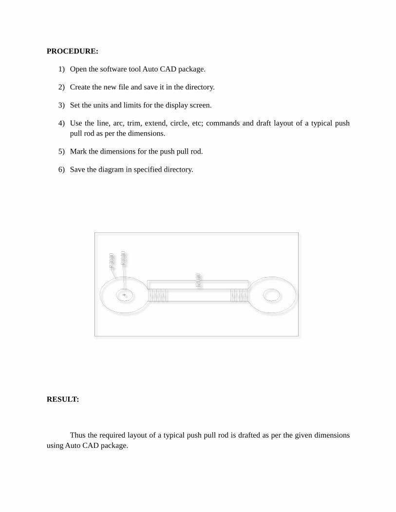
AIM:
To draft the layout of a typical push pull rod with necessary dimensions using 2D drafting
software.
DESCRIPTION:
The push pull rod is used between bell crank and from bell crank to torque arms
(“horns”) to transmit the force and motion from one to the other. A push-pull rod connected to a
bell crank is shown in fig. push pull rods are also called control rods because they are often in
control systems.
SOFTWARE USED:
Auto CAD
COMMANDS USED:
Limits
Zoom – All
Line
Arc
Circle
Polygon
Spline
Trim
Erase
Copy
Mirror
Move
Chamfer
Fillet
Hatch
Rotate
Text
Dimension – Linear, Radius, Angular
Save
PROCEDURE:
1) Open the software tool Auto CAD package.
2) Create the new file and save it in the directory.
3) Set the units and limits for the display screen.
4) Use the line, arc, trim, extend, circle, etc; commands and draft layout of a typical push
pull rod as per the dimensions.
5) Mark the dimensions for the push pull rod.
6) Save the diagram in specified directory.
RESULT:
Thus the required layout of a typical push pull rod is drafted as per the given dimensions
using Auto CAD package.

THREE VIEW DIAGRAM OF A TYPICAL AIRCRAFT
EX. No. 7
DATE:
AIM:
To draft three view diagram of a typical aircraft with necessary dimensions using 2D
drafting software.
SOFTWARE USED:
Auto CAD
COMMANDS USED:
Limits
Zoom – All
Line
Arc
Circle
Polygon
Spline
Trim
Erase
Copy
Mirror
Move
Chamfer
Fillet
Hatch
Rotate
Text
Dimension – Linear, Radius, Angular
Save

PROCEDURE:
1) Open the software tool Auto CAD package.
2) Create the new file and save it in the directory.
3) Set the units and limits for the display screen.
4) Use the line, arc, trim, extend, circle, etc; commands and draft three view diagram of a
typical aircraft as per the dimensions.
5) Mark the dimensions for the fuselage.
6) Save the diagram in the specified directory.
RESULT:
Thus the required three view diagram of a typical aircraft is drafted as per the given
dimensions using Auto CAD package.

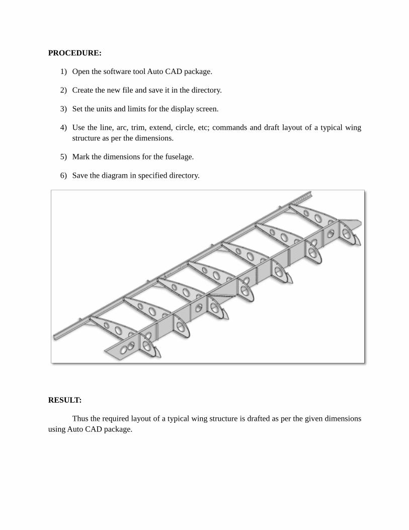
LAYOUT OF A TYPICAL WING STRUCTURE
EX. No. 8
DATE:
AIM:
To draft the layout of a typical wing structure with necessary dimensions using 2D
drafting software.
SOFTWARE USED:
Auto CAD
COMMANDS USED:
Limits
Zoom – All
Line
Arc
Circle
Polygon
Spline
Trim
Erase
Copy
Mirror
Move
Chamfer
Fillet
Hatch
Rotate
Text
Dimension – Linear, Radius, Angular
Save
PROCEDURE:
1) Open the software tool Auto CAD package.
2) Create the new file and save it in the directory.
3) Set the units and limits for the display screen.
4) Use the line, arc, trim, extend, circle, etc; commands and draft layout of a typical wing
structure as per the dimensions.
5) Mark the dimensions for the fuselage.
6) Save the diagram in specified directory.
RESULT:
Thus the required layout of a typical wing structure is drafted as per the given dimensions
using Auto CAD package.

LAYOUT OF TYPICAL FUSELAGE STRUCTURE
EX. No. 9
DATE:
AIM:
To draft the Layout of typical fuselage structure with necessary dimensions using 2D
drafting software.
SOFTWARE USED:
Auto CAD
COMMANDS USED:
Limits
Zoom – All
Line
Arc
Circle
Polygon
Spline
Trim
Erase
Copy
Mirror
Move
Chamfer
Fillet
Hatch
Rotate
Text
Dimension – Linear, Radius, Angular
Save

PROCEDURE:
1. Open the software tool Auto CAD package.
2. Create the new file and save it in the directory.
3. Set the units and limits for the display screen.
4. Use the line, arc, trim, extend, circle, etc; commands and draft the fuselage structure as
per the dimensions.
5. Mark the dimensions for the fuselage structure.
6. Save the diagram in specified directory.
RESULT:
Thus the required layout of the fuselage structure is drafted as per the given dimensions
using Auto CAD package.

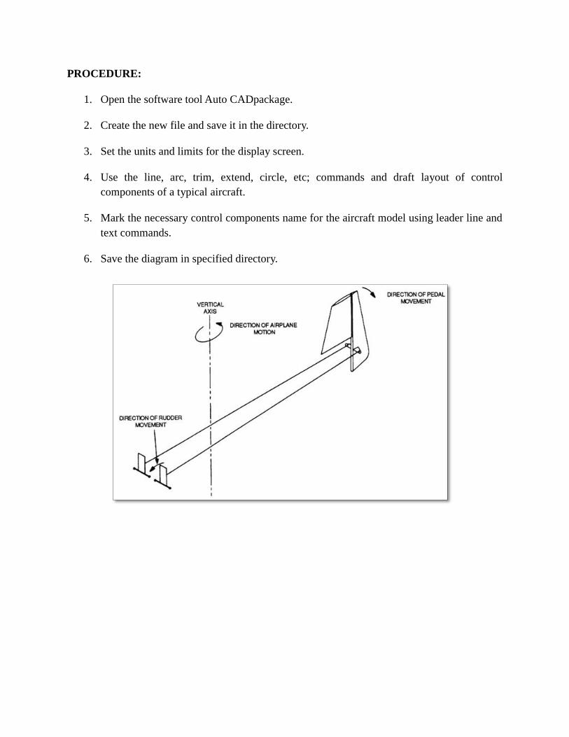
LAYOUT OF CONTROL SYSTEM
EX. No. 10
DATE :
AIM:
To draft the layout of control components for an aircraft model with necessary parts using
2D drafting software.
SOFTWARE USED:
Auto CAD
COMMANDS USED:
Limits
Zoom – All
Line
Arc
Circle
Polygon
Spline
Trim
Erase
Copy
Mirror
Move
Chamfer
Fillet
Hatch
Rotate
Leader line
Text
Dimension – Linear, Radius, Angular
Save
PROCEDURE:
1. Open the software tool Auto CADpackage.
2. Create the new file and save it in the directory.
3. Set the units and limits for the display screen.
4. Use the line, arc, trim, extend, circle, etc; commands and draft layout of control
components of a typical aircraft.
5. Mark the necessary control components name for the aircraft model using leader line and
text commands.
6. Save the diagram in specified directory.

RESULT:
Thus the required layout of control components for an aircraft model is drafted with
necessary parts using Auto CAD package.