cadastral survey guidelines february 2019 - sa.gov.au · requires that a plan of cadastral survey...
TRANSCRIPT
Cadastral Survey Guidelines
KNet 11757936 V3 February 2019 Page 0 of 163
Cadastral
Survey
Guidelines
February 2019 Version 3.0
KNet# 11757936
Cadastral Survey Guidelines
KNet 11757936 V3 February 2019 Page 1 of 163
Table of Contents
Contact Details
1 Introduction & Surveyor-General's Directions
1.1 Introduction
1.2 Controlling Legislation
1.3 Exemption from Survey Instructions
Attachment: Surveyor-General’s Directions
Direction 1 Accuracy of Surveys
Direction 2 Survey Marks
Direction 3 Certification of Plans
Direction 4 Survey Reports
Direction 5 Exemptions
2 The Geodetic Network
2.1 Introduction
2.2 Controlling Legislation
2.3 Coordinates of PSMs
2.4 Survey Mark Database Coordinate Accuracy
2.5 Providing PSM Coordinates to the Surveyor-General
2.6 Accuracy of Coordinates Provided by Surveyors
2.7 Reporting Coordinate Errors
2.8 Coordination of EWS Benchmarks
3 Statutory Provisions
3.1 Introduction
3.2 Real Property Act 1886
3.3 Strata Titles Act 1988
3.4 Community Titles Act 1996
3.5 Development Regulations 1993
3.6 Liquor Licensing (General) Regulations 2012
Cadastral Survey Guidelines
KNet 11757936 V3 February 2019 Page 2 of 163
4 Survey Principles & Case Law Rulings
4.1 Introduction
4.2 Controlling Legislation
4.3 Intention
4.4 Evaluation of Evidence
4.5 Lost & Confused Boundaries
4.6 Monuments
4.7 Abuttals
4.8 Marks
4.9 Occupation
4.10 Measurement
4.11 Distribution of Data Differences
4.12 Identification Surveys
4.13 Public Roads
4.14 Adverse Possession
4.15 Encroachment of Buildings
4.16 References & Bibliography
5 Coordinated Cadastre
5.1 Introduction
5.2 Controlling Legislation
Attachment: Index of Designated Survey Areas
6 Confused Boundary Areas
6.1 Introduction
6.2 Controlling Legislation
6.3 Identification & Declaration of Confused Boundary Areas
6.4 Considerations in Determining Boundaries in CBAs
6.5 Consultation, Objections & Alterations
7 Occupation
7.1 Introduction
7.2 Controlling Legislation
7.3 Requirement for Occupation Information
7.4 Location Point
7.5 Description
7.6 Miscellaneous
Cadastral Survey Guidelines
KNet 11757936 V3 February 2019 Page 3 of 163
8 Crown Lands & Crown Tenures Survey Policy
8.1 Introduction
8.2 Freeholding Survey Policy
8.3 Application of Freeholding Survey Policy
8.4 Freeholding Waterfront Perpetual Leases
8.5 Pastoral Leases
8.6 National Parks in Pastoral Areas
9 Searching
9.1 Introduction
9.2 Controlling Legislation
9.3 Title Searching
9.4 Survey Searching
10 Calibration of Surveying Equipment
10.1 Introduction
10.2 Controlling Legislation
10.3 General Error Sources
10.4 Calibration Certificate
10.5 Calibration of EDM Equipment
10.6 Calculation of Verification Parameters
Attachments:
Mawson Lakes EDM Base Pillar Locations & Access
Mawson Lakes EDM Base Field Notes
Baseline Software Manufacturer’s Specifications for EDM Instruments
11 Historical Survey Marking Practices
11.1 Introduction
11.2 Crown Surveys: Marking Practices
11.3 Crown Surveys: Surveying Practices
11.4 Freehold Surveys: Marking Practices
11.5 Freehold Surveys: Surveying Practices
11.6 Mineral Tenures
11.7 Preservation of Old Cadastral Marks
Attachments:
Extracts from Handbook for Government Surveyors
Summary of Historical Marking Practices
Cadastral Survey Guidelines
KNet 11757936 V3 February 2019 Page 4 of 163
12 Natural Boundaries
12.1 Introduction
12.2 Controlling Legislation
12.3 Tidal Boundary Definitions and Principles
12.4 Methods for Determining MHWM
12.5 Heights of Coastal Land
12.6 Non Tidal Boundary Definitions and Principles
12.7 Accretion & Erosion
12.8 The Waterfront Reserve/Road Boundary
12.9 References & Bibliography
13 Survey Accuracies
13.1 Introduction
13.2 Controlling Legislation
13.3 Accuracy Zones
13.4 Tolerances
13.5 Survey Specifications
13.6 Reliability
13.7 Occupation
14 Marking Requirements for Surveys
14.1 Introduction
14.2 Controlling Legislation
14.3 Permanent and State Survey Marks
14.4 Survey Pegs
14.5 Boundary Marks
14.6 Final Marking of Divisions of More Than 5 Allotments/Lots
14.7 Non PSM Reference Marks
15 Connection to Previous Surveys
15.1 Introduction
15.2 Controlling Legislation
15.3 Survey Search
15.4 Extent of Survey & Connection Requirements
15.5 Marks Shown Gone
15.6 Breaking of Pavements
15.7 Showing Redundant & Inaccessible Reference Marks
Cadastral Survey Guidelines
KNet 11757936 V3 February 2019 Page 5 of 163
16 Field Notes
16.1 Introduction
16.2 Controlling Legislation
16.3 Presentation Standards
17 Survey Reports
17.1 Introduction
17.2 Controlling Legislation
17.3 Reports Requested on Particular Surveys
17.4 Reports Required on All Surveys
17.5 Example Descriptive Reports
18 Audit Surveys and Rectifications
18.1 Introduction
18.2 Controlling Legislation
18.3 Rectifications
18.4 Audit Program Survey Selection
18.5 Audit Notification and Supply of Field Notes
18.6 Audit Reports
18.7 Reporting on Redefinition
18.8 Response to Audit Findings
18.9 Error Assessment
18.10 Survey Assessment
18.11 Audit Review & Surveyor Risk Rating
19 Miscellaneous
19.1 Trust Grants
19.2 Public Map
19.3 Limited Examination of Diagram Book Pages
19.4 Surveys for Aquaculture Leases
Appendices
A. Certified Survey Plan Checklist
Cadastral Survey Guidelines
KNet 11757936 V3 February 2019 Page 6 of 163
Contact Details
Department of Planning, Transport & Infrastructure (DPTI)
Land Boundaries Section Email: [email protected]
Level 2, 101 Grenfell Street Adelaide SA 5000
GPO Box 1354 Adelaide SA 5001
Surveyor-General
Mike Burdett Phone: (08) 8226 4036 Email: [email protected]
Cadastral Specialist
Bradley Slape Phone: (08) 8226 3584 Email: [email protected]
Survey Operations Unit
Team Leader Andrew Falkenberg Phone: (08) 8226 1360 Email: [email protected]
Senior Cadastral Surveyor
Peter Brinkley Phone: (08) 8226 1330 Email: [email protected]
Survey Mark Enquiries
Survey Data Officer
Phone: (08) 8226 1291 Email: [email protected]
EDM Base Enquiries
Phone: (08) 8226 1334 Email: [email protected]
Survey Depot
Appointment Only (Not permanently staffed) Phone: (08) 8226 1416 Building 11 300 Richmond Rd Netley SA 5037
Spatial Maintenance Unit
Spatial Data Enquiries
Team Leader Phone: (08) 8463 3756 Email: [email protected]
Land Services SA (LSSA) – Lands Titles Office
General Enquiries, Client Advice and reporting SAILIS search errors
Ground Floor 101 Grenfell St Adelaide SA 5000 Phone: (08) 8423 5000 Toll free 1800 648 176 Email: [email protected]
Plan related enquires Email: [email protected]
General Registry Office & Old Systems Unit
Phone: (08) 8423 5059
Cadastral Survey Guidelines
KNet 11757936 V3 February 2019 Page 7 of 163
1. Introduction and Surveyor-General’s Directions
1.1 Introduction
These Cadastral Survey Guidelines (CSG) are published by the Surveyor-General and have been prepared for licensed surveyors undertaking cadastral surveys in South Australia. Cadastral survey practice in South Australia is regulated by a four tiered structure, the component parts being:
Survey Act 1992.
Survey Regulations 2007.
Surveyor-General's Directions.
Cadastral Survey Guidelines & Plan Preparation Guidelines (PPG).
Surveyor-General's Directions are promulgated by publication in the Gazette. Regulation 19 requires that a plan of cadastral survey lodged in the LTO must comply with the PPG.
The CSG provides information and guidelines supplementing survey instructions and other legislative requirements. This includes guidance as to acceptable survey practice, including plan preparation, to more easily comply with requirements in unusual cases. The CSG also provides information about land boundary common and statute law.
As the CSG is issued under the authority of the Surveyor-General, surveyors must have regard to any of its guidelines (not covered elsewhere by survey instructions) that are expressed as recommendations.
1.2 Controlling Legislation
Section 43 of the Act provides for the issue of regulated survey instructions:
43 (3) Survey instructions may -
(b) confer discretionary powers on the Surveyor-General.
This is expanded in the Regulations:
27 - Directions of Surveyor-General
(1) The Surveyor-General may issue written directions in relation to cadastral surveys and
records of cadastral surveys for the purposes of this Part.
(2) The directions may, for example-
(a) approve a class of marks as reference marks or State survey marks;
(b) approve a class of materials as materials of which survey pegs may be composed;
(c) regulate the marking of boundaries of land in cadastral surveys, including the
placement or acceptance of survey marks in cadastral surveys;
(d) regulate the placement of permanent survey marks or State survey marks in the
course of cadastral surveys (including the number and position of the marks and
the standard of accuracy that must be achieved in placing the marks) and regulate
the provision to the Surveyor-General of information relating to the marks once
placed (including the location of the marks and, in the case of permanent survey
marks, sufficient measurements to allow the Map Grid of Australia coordinates of
the marks to be determined);
(e) fix tolerances in relation to the standard of accuracy of cadastral surveys required
to be met for the purpose of these regulations;
(f) require and regulate the provision to the Surveyor-General or any other specified
authority of information relating to mathematical checking of cadastral surveys
prior to lodging a survey plan;
Cadastral Survey Guidelines
KNet 11757936 V3 February 2019 Page 8 of 163
(g) require reports to be provided in relation to specified classes of survey;
(h) approve forms for the purpose of this Part;
(i) grant exemptions (which may be absolute or conditional) from compliance with
the directions or any specified provision of the directions;
(j) otherwise regulate the performance of cadastral surveys.
(3) A direction under these regulations may be of general or limited application
according to the class of survey to which it applies, the circumstances of the
application or any other specified factor.
(6) A surveyor must comply with directions of the Surveyor-General promulgated under
this part.
1.3 Exemption from Survey Instructions
Regulation 25 provides:
25 - Exemptions by Surveyor-General
(1) The Surveyor-General may, on application by a surveyor, exempt the surveyor from
any specified requirement of this Part in relation to a specified cadastral survey if
compliance is not practicable or the surveyor wishes to use an alternative method of
survey and the Surveyor-General is satisfied that the accuracy of the survey will not
be jeopardised.
(2) The Surveyor-General may issue directions exempting a class of surveys from any
specified requirement of this part.
(3) An exemption under this regulation may be subject to conditions and may be
subsequently varied or revoked.
A licensed surveyor seeking exemption from any of the requirements of Part 3 (Survey instructions) of the Regulations, including Surveyor-General's Directions, must set down the reasons in writing and forward them to the Cadastral Specialist (see Contact Details).
Exemptions should be sought prior to the survey’s plan lodgement, preferably prior to the survey’s field work completion.

Cadastral Survey Guidelines
KNet 11757936 V3 February 2019 Page 9 of 163
SURVEYOR-GENERAL'S DIRECTIONS
Issued Pursuant To Regulations 25(2) and 27 of the Survey Regulations 2007
Direction 1 - Accuracy of Surveys
1.1 Application of this Direction
This Direction details the standards of accuracy required for cadastral surveys, and action required of surveyors where differences with published coordinates of permanent survey marks (PSMs) and state survey marks (SSMs) do not meet standards of accuracy.
1.2 Definitions
In this Direction:
Adelaide City means land within the City of Adelaide.
High density urban means urban area land parcels that are less than 1000m² in area.
Low density urban means urban area land parcels that are 1000m² or greater in area.
Map Grid of Australia means, for surveys conducted prior to these Directions commencing operation, MGA94 (see below) and, for surveys conducted after commencement of the operation of these Directions, MGA2020 (see below)
MGA2020 (Map Grid of Australia 2020) means the system of rectangular co-ordinates derived from a Universal Transverse Mercator projection of latitudes and longitudes that are based on the Geocentric Datum of Australia 2020 (GDA2020) within the meaning of the National Measurement (Recognized-Value Standard of Measurement of Position) Determination 2017 dated 11 October 2017 and registered on the Federal Register of Legislation on 13 October 2017 and specified in Geocentric Datum of Australia 2020 Technical Manual (technical manual link - http://www.icsm.gov.au/sites/default/files/GDA2020TechnicalManualV1.1.1.pdf )
MGA94 (Map Grid of Australia 1994) means the Map Grid of Australia 1994 specified in the GDA Technical Manual (1994) of the Intergovernmental Committee on Surveying & Mapping ( http://www.icsm.gov.au/sites/default/files/2017-09/gda-v_2.4_0.pdf )
Rural area means locations that are not included in urban areas or Adelaide City.
Urban area means locations where land parcels are generally less than 5000m² in area that are not included in Adelaide City.
1.3 Tolerances
1.3.1 Polygon Misclosure
The horizontal perimeter misclosure of surveyed polygons on plans shall not exceed 0.02 metres plus one part in 20 000 of the perimeter distance.
Cadastral Survey Guidelines
KNet 11757936 V3 February 2019 Page 10 of 163
1.3.2 Marks and Improvements
The difference in the horizontal position, and the difference in the vertical position, of survey marks, reference marks and improvements placed or connected in the survey, and the position of those survey marks and improvements as determined from measurements shown on the plan must not exceed in:
Adelaide City: 0.03 metres
High density urban: 0.03 metres
Low density urban: 0.05 metres
Rural areas: 0.10 metres.
Where survey marks, reference marks or improvements are adjacent to a boundary between different accuracy zones the tolerance of the higher accuracy zone shall apply.
1.3.3 Coordination or Heighting of Permanent and State Survey Marks
The difference in the horizontal or vertical position of permanent and state survey marks and the position of those marks as determined from the MGA2020 coordinates or heights provided by the surveyor, relative to the existing coordinated Permanent or State survey marks, must not exceed in:
Adelaide City: 0.015 metres
Urban areas: 0.02 metres
Rural areas: 0.05 metres.
1.3.4 Connection to Coordinated and/or Heighted Permanent and State Survey Marks
If the distance difference or lateral displacement (caused by the angular or bearing difference) between their survey and the MGA2020 coordinates of the permanent or state survey marks in the geodetic dataset published by the Surveyor-General, or the height difference between their survey and the heights of the permanent or state survey marks in the geodetic dataset published by the Surveyor-General, exceed on surveys in:
Adelaide City: 0.03 metres,
Urban areas: 0.05 metres, or
Rural areas: 0.10 metres
surveyors must:
(a) verify their survey by some other means,
(b) identify the permanent survey mark(s) whose coordinates or heights appear to
be the cause of the above relative tolerances being exceeded,
(c) not adjust their survey to the permanent survey mark coordinates or heights
identified as the cause of the above relative tolerances being exceeded,
(d) re-coordinate and/or re-height the permanent survey mark(s) identified as the
cause of the above relative tolerances being exceeded, and
(e) report the permanent survey mark coordinates and/or heights, as relevant,
identified as the cause of the above relative tolerances being exceeded, in a
manner specified in Surveyor-General’s Direction 4.
The requirement to report permanent survey mark coordinates and/or heights in (e) above may be ignored if the published positional uncertainty (PU) for a PSM’s or SSM’s coordinate and/or height, as relevant, exceeds 0.03m in Adelaide City, 0.05m in urban areas, or 0.10m in rural areas.
Cadastral Survey Guidelines
KNet 11757936 V3 February 2019 Page 11 of 163
Direction 2 - Survey Marks
2.1 Application of this Direction
This Direction details the PSM (permanent survey mark), SSM (state survey mark), reference mark and survey peg requirements for cadastral surveys whose plans, excluding plans for information purposes, are lodged in the Lands Titles Registration Office. The requirements may include both placed and existing marks connected, and provision of information to the Surveyor-General.
2.2 Definitions
In this Direction:
Map Grid of Australia means, for surveys conducted prior to these Directions commencing operation, MGA94 (see below) and, for surveys conducted after commencement of the operation of these Directions, MGA2020 (see below)
MGA2020 (Map Grid of Australia 2020) means the system of rectangular co-ordinates derived from a Universal Transverse Mercator projection of latitudes and longitudes that are based on the Geocentric Datum of Australia 2020 (GDA2020) within the meaning of the National Measurement (Recognized-Value Standard of Measurement of Position) Determination 2017 dated 11 October 2017 and registered on the Federal Register of Legislation on 13 October 2017 and specified in Geocentric Datum of Australia 2020 Technical Manual (technical manual link - http://www.icsm.gov.au/sites/default/files/GDA2020TechnicalManualV1.1.1.pdf )
MGA94 (Map Grid of Australia 1994) means the Map Grid of Australia 1994 specified in the GDA Technical Manual (1994) of the Intergovernmental Committee on Surveying & Mapping ( http://www.icsm.gov.au/sites/default/files/2017-09/gda-v_2.4_0.pdf )
Urban area means locations where land parcels are generally less than 5000m² in area.
Rural area means locations outside urban areas.
2.3 Permanent and State Survey Marks
PSMs shall be identified by the symbol .
Three types of survey mark have been gazetted as PSMs pursuant to Section 49(3) of the Survey Act 1992:
below ground PSMs
above ground PSMs
stainless steel pins, at least 50mm long and 5mm in diameter, with inscribed washer
suitable for permanent installation in concrete (mini PSMs).
The last of these, mini PSMs, are restricted to placement in community divisions and subdivisions of more than 5 allotments (see Cadastral Survey Guidelines section 14.3 for more detail).
SSMs are survey marks constructed to the same specifications set for PSMs and shall be identified by the symbol .
Brass survey mark plaques, provided by the Surveyor-General, shall be used on all new PSMs & SSMs, other than mini PSMs.
Cadastral Survey Guidelines
KNet 11757936 V3 February 2019 Page 12 of 163
2.3.1 Requirement to Connect and Place Permanent and State Survey Marks
Further to regulations 14, 15 and 22 Survey Regulations 2007:
2.3.1.1 Connection
Surveys must connect to at least three PSMs or two PSMs and one SSM in urban areas, or three SSMs in rural areas, existing or new. If any two or more of the marks are within a 100m radius of each other in urban areas, or within a 500m radius of each other in rural areas, they shall count as only one mark for the purposes of this requirement.
2.3.1.2 Spacing
PSMs and SSMs within the survey are required at 200m spacing from other PSMs and SSMs in urban areas and 2000m spacing from other PSMs & SSMs in rural areas. See the Cadastral Survey Guidelines section 14 for application of these spacing. If PSMs or SSMs connected, existing or new, do not satisfy these spacing then additional PSMs shall be placed.
2.3.1.3 Whole to Part
If PSMs or SSMs connected, existing or new, as required in 2.3.1.1 and 2.3.1.2 above do not provide sound geometric control for the survey then additional PSMs or SSMs, existing or new, are required to be connected to provide sound geometric control.
2.3.1.4 Divisions of More Than Five Allotments/Lots
On plans for division of land into more than 5 allotments or lots the Surveyor-General, following receipt of the proposal plan, shall advise the surveyor carrying out the division of the number and location of new PSMs or SSMs, based on 2.3.1.1, 2.3.1.2 & 2.3.1.3 above. The PSM/SSM configuration may include some mini PSMs for use in kerbs; see the Cadastral Survey Guidelines section 14 for required locations of these mini PSMs.
Where no certificate of practical completion has been issued for division of land into more than 5 allotments or lots, and PSMs or SSMs have not been reinstated, the surveyor who has carried out the survey must place the PSMs or SSMs otherwise required under regulation 23 of the Survey Regulations 2007 within two years of the plan’s deposit by the Registrar-General.
2.3.1.5 Potential Infrastructure Destruction
Surveyors undertaking surveys for infrastructure projects are responsible for replacing PSMs and SSMs disturbed, or threatened with destruction, through those projects.
2.3.2 Protecting Permanent and State Survey Marks
In all areas PSMs and SSMs shall be placed in safe locations where they are least likely to be disturbed. Below ground marks placed shall be set at least 200mm below ground level to allow encasement in urban areas and to reduce the risk of being disturbed in rural areas.
Below ground PSMs or SSMs shall be protected by a cast iron cover suitably supported by a 195 millimetre diameter PVC pipe:
when placed in urban areas
on re-establishment of the pavement after existing PSMs or SSMs are found in
place below pavements.
Cadastral Survey Guidelines
KNet 11757936 V3 February 2019 Page 13 of 163
PSMs and SSMs shall be witnessed by a steel dropper with a witness plate attached:
when placed in rural areas
if existing PSMs and SSMs connected in rural areas are not already witnessed by
a dropper, or the witness dropper and/or its plate are in a state of disrepair such
that they no longer serve their purpose
if not practicable to protect below ground PSMs and SSMs placed in urban areas
with a cast iron cover
when placed below ground in divisions of land in urban areas of more than 5
allotments or lots (as well as the cover required above).
Witness droppers shall be placed to best protect the PSM/SSM, and to be in safe locations. In urban areas witness droppers shall be encased in a PVC sleeve; a rolled witness plate shall instead be fixed to the PVC sleeve.
The witness plates to be used on steel droppers or PVC sleeves shall be those provided by the Surveyor-General, with the relevant details of the PSM’s location marked on the witness plate in a permanent manner.
A location plan prepared on sheets provided by the Surveyor-General shall be supplied by the surveyor for every PSM placed on a survey.
PSMs shown placed or connected on survey plans lodged in the Lands Titles Office must have their location on the plan related to adjacent improvements or other physical features. This requirement will not apply to PSMs in urban areas that have been previously connected to the cadastre and are obvious on the ground.
2.3.3 Coordination or Heighting of Permanent and State Survey Marks
Surveyors shall determine, and provide to the Surveyor-General:
MGA2020 coordinates of PSMs and SSMs they place,
MGA2020 coordinates of existing PSMs and SSMs they connect that have
coordinates, in the geodetic dataset published by the Surveyor-General, with no
PU or a PU greater than or equal to 0.10m,
MGA2020 coordinates and/or heights, as relevant, of existing PSMs and SSMs
connected where their survey differs to current coordinates and/or heights by
more than tolerances set by Surveyor-General’s Direction 1.3.4
The provision of coordinates and heights shall be undertaken in accordance with section 2 of the Cadastral Survey Guidelines.
2.4 Survey Pegs and reference marks
While it is necessary to mark every new boundary point defined on a cadastral survey with a survey peg or reference mark it is not necessary to mark existing boundaries redefined.
Pursuant to regulation 10 of the Survey Regulations 2007 the following are approved as
survey pegs:
(a) a peg of a durable nature, composed of wood, metal, plastic or other material approved for the purpose by the Surveyor-General, measuring at least 300 millimetres in length and 50 millimetres square at the top and coloured white; or
(b) a metal spike of at least 300 millimetres in length to which is mounted a metal or plastic top of durable material, at least 50 millimetres square and coloured white; or
Cadastral Survey Guidelines
KNet 11757936 V3 February 2019 Page 14 of 163
(c) a star dropper of at least 300 millimetres in length and coloured white.
Where it is not practicable to drive a survey peg of the type specified in regulation 10 of the Survey Regulations 2007, due to fencing, walls or permanent covering of the boundary, the following reference marks may be used as alternatives to survey pegs:
a galvanised iron nail driven into the fence and painted white
a masonry nail or screw secured into the wall or pavement and painted
white
a deck spike at least 100 millimetres in length and 8 millimetres in
diameter driven into bitumen and painted white.
Where it is not practicable to peg the actual boundary corner a position offset to the boundary corner is to be pegged using a reference mark.
Where a survey peg marking a boundary is not visible from an adjacent peg, survey pegs shall be placed along the new boundary so that from any survey peg on the boundary the adjacent survey pegs are visible.
New boundaries need not be pegged if their improvements are within one metre of the boundary, and the relationship between the boundary and the improvement is shown on the plan.
If the survey is for a division of land into more than 5 allotments or lots, the allotment or lot numbers must be placed, in a permanent and durable manner, on the top or face of each survey peg of the types specified in regulation 10 of the Survey Regulations 2007.
Where no certificate of practical completion has been issued for division of land into more than 5 allotments or lots, and survey pegs have not been reinstated, the surveyor who has carried out the survey must place the survey pegs otherwise required under regulation 23 of the Survey Regulations 2007 within two years of the plan’s deposit by the Registrar-General.
Cadastral Survey Guidelines
KNet 11757936 V3 February 2019 Page 15 of 163
Direction 3 - Certification of Plans
3.1 Application of this Direction
This Direction details the form for certification of plans of cadastral survey, the requirement for currency of field work represented in a certified plan, and the supervision responsibilities of surveyors certifying cadastral surveys. Plans under the Community Titles Act 1996 are not required to carry the certification below, however,
they are a cadastral survey, requiring compliance with survey instructions.
3.2 Certification
The surveyor responsible for any plan of cadastral survey, other than those carried out under the Community Titles Act 1996, to be lodged in the Land Titles Registration Office
shall complete and endorse the following certificate on the plan of survey:
I ................……….. licensed surveyor of South Australia do hereby certify -
(1) That this plan has been made from surveys carried out by me or under my personal supervision and in accordance with the Survey Act 1992.
(2) That the field work was completed on the ........ day of ........…….. 20… excepting for the final placement of survey marks. (strike out if not applicable)
Date ................ ………........................................... Licensed Surveyor
The exception provided in clause (2) of the certification is restricted to surveys affected by the requirements of regulation 23 of the Survey Regulations 2007.
3.3 Marking & Improvements Within Two Years of Lodgement
Field work carried out more than two years prior to the date a plan of cadastral survey is lodged in the Lands Titles Registration Office must be checked to confirm whether marking and improvements remain the same:
pegging of new corners must be reinstated if disturbed or missing
any alteration to the status or position of other marks and improvements must be
reflected on the plan.
The date of field work completion in clause (2) of the certification shall then signify this checking was done within two years.
3.4 Supervision
A surveyor endorsing the certification of a plan of cadastral survey is responsible for the survey irrespective of whether it was carried out by them or under their supervision. A surveyor carrying out a survey under their supervision shall ensure that the survey reflects their professional responsibilities, and complies with relevant legislation, directions and guidelines.
Cadastral Survey Guidelines
KNet 11757936 V3 February 2019 Page 16 of 163
Direction 4 - Survey Reports
4.1 Application of this Direction
This Direction details the requirement for providing reports on cadastral surveys.
4.2 Reports Requested on Particular Surveys
A surveyor must provide the Surveyor-General with a survey report in relation to their cadastral surveys, within 14 days of receiving a written request from the Surveyor-General for such a report. The request from the Surveyor-General may cover all or certain survey types over a period of time or until a particular event occurs. The reports must include information, and be in a form, required by the Surveyor-General.
4.3 Reports Required on All Prescribed Cadastral Surveys
A survey report is required for all prescribed cadastral surveys lodged in the Lands Titles Registration Office.
The following are prescribed cadastral surveys for the purpose of Regulation 18(3):
A survey certified by a licensed survey required for a transaction pursuant to the
administration of the Real Property Act 1886 with the exception of a plan of land
division creating six or more allotments where the outer boundary survey has been
accepted for filing or deposited in the Lands Titles Office (LTO)
An “outer boundary” survey certified by a licensed surveyor for a development
pursuant to the Community Titles Act 1996
A survey certified by a licensed surveyor required for a transaction under the Roads
(Opening and Closing) Act 1991
A survey of Crown land certified by a licensed surveyor for deposit or filing in the
LTO
The Survey Report must contain a completed Certified Survey Plan Checklist, of a form specified in Appendix A of the Cadastral Survey Guidelines (or an expanded version), and a written report.
Survey reports must be attached to the plan lodged in the Lands Titles Registration Office at the time of lodgement and meet the following content criteria:
4.3.1 Boundary Data Discrepancies
A detailed survey report is required If the survey reveals differences with previously lodged plans greater than the following:
3 minutes in the angle of road alignments at any road junction or bend on an
urban survey
3 minutes in any angle on a rural survey
0.1m + 1/2000 length ratio in any distance
0.15m in the position of any boundary corner on an urban survey
1m in the position of any boundary corner on a rural survey.
Cadastral Survey Guidelines
KNet 11757936 V3 February 2019 Page 17 of 163
Detailed survey reports must disclose any differences between the survey as lodged and previous surveys, defining or redefining common boundary points, together with any other information which may be of assistance in assessing the accuracy and reliability of the redefinition of the boundaries of the land under survey. Detailed survey reports shall be in the form of a written report or an annotated copy of the survey plan. For further details refer to section 17 of the Cadastral Survey Guidelines.
In all other cases, a less detailed survey report identifying and commenting on differences (if any) between the survey as lodged and previous surveys shall be acceptable. If there are no material differences with other surveys a statement to that affect will suffice.
4.3.2 PSMs Gone
Where a permanent survey mark is shown Gone by a surveyor their survey report shall describe the steps taken to locate the permanent survey mark and the likely cause of its destruction.
4.3.3 Natural Boundaries
Where a survey redefines a natural boundary the survey report shall describe the method adopted to locate the boundary. If there is significant difference in the position of any part of the natural boundary to its previously surveyed position the survey report must address potential reasons for this apparent movement.
4.3.4 PSM Coordinate and Height Discrepancies
Where a survey’s connection to permanent survey marks results in differences to the coordinates or heights in the geodetic dataset published by the Surveyor-General exceeding the tolerances specified in Surveyor-General’s Direction 1.3.4, the surveyor must report the discrepancy using the online coordinate error report form and provide an updated MGA2020 coordinate for that permanent survey mark. For further details refer to section 2.5a of the Cadastral Survey Guidelines.
The surveyor must endorse the form’s certification that they have verified their measurements in relation to detecting the coordinate or height discrepancy. A surveyor must not make such an endorsement unless they have verified their observations through independent measurements.
Cadastral Survey Guidelines
KNet 11757936 V3 February 2019 Page 18 of 163
Direction 5 - Exemptions
In accordance with Regulation 25 of the Survey Regulations 2007, the Surveyor-General
exempts the following:
1. Adjustment of Surveys
Surveys of land in designated survey areas are exempt from the requirement of Regulation 22(b) of the Survey Act 1992.
2. Final Marking
Surveyors are exempt from the requirement of Regulation 23 of the Survey Act 1992, as regards reinstating pegs marking:
boundaries of reserves which abut other reserves or roads.
boundaries of reserves and roads which abut the balance allotment in staged developments.
3. Community Plans
Primary plans (but not including substitute or added sheets) under the Community Titles Act 1996 which create boundaries requiring no new PSMs are exempt from showing connection required under Regulation 11(2)(a) and (b) of the Survey Act 1992.
4. Map Grid of Australia
Certified cadastral surveys outside of Designated Survey Areas (DSAs) lodged with Land Services SA are exempt from the requirements of Direction 2, 2.3.3: co-ordination and/or height requirements in accordance with MGA2020, between 7 February 2019 and 30 April 2019. The requirements in 2.3.3 of Direction 2 for all certified surveys shall take effect from 1 May 2019.
Cadastral Survey Guidelines
KNet 11757936 V3 February 2019 Page 19 of 163
2 The Geodetic Network
2.1 Introduction
The State geodetic network is constructed at three basic levels, primary, secondary and tertiary. The primary network is continental in scale and consists of stations separated by distances of tens of kilometres; it covers the whole State.
The secondary network is not a continuous framework as its main purpose is to break down the primary network to a suitable density for controlling localised projects. Distances between stations are typically 5 kilometres.
The tertiary network is the working level for most project work including cadastral surveys, large scale mapping, and DCDB control. The tertiary network enables surveys to be tied to the State geodetic survey system interrelated by the common survey framework. Stations at this level are separated by approximately 200m to 2km depending on locality and land use.
Published mark coordinates in South Australia are projected from the Geocentric Datum of Australia 2020 (GDA2020). Refer to the GDA Technical Manual for explanations, formulae, worked examples and spreadsheet templates on the datum.
2.2 Controlling Legislation
Section 49 of the Survey Act 1992 provides the legislative authority for the Surveyor-General to
establish a control network:
49 - Coordinated cadastre
(1) The Surveyor-General is responsible for establishing a coordinated cadastre for the State and may, for that purpose-
(a) establish and maintain a network of permanent survey marks with recorded coordinates for use in surveying, mapping or related practice;
The Survey Regulations 2007 provide for directions which, amongst other things, gives the
Surveyor-General the authority to specify PSM requirements:
27—Directions of Surveyor-General
(1) The Surveyor-General may issue written directions in relation to cadastral surveys and records of cadastral surveys for the purposes of this Part.
(2) The directions may, for example—
(d) regulate the placement of permanent survey marks or State survey marks in the course of cadastral surveys (including the number and position of the marks and the standard of accuracy that must be achieved in placing the marks) and regulate the provision to the Surveyor-General of information relating to the marks once placed (including the location of the marks and, in the case of permanent survey marks, sufficient measurements to allow the Map Grid of Australia coordinates of the marks to be determined);
SGD 2.3.1 provides direction in the minimum number of PSMs required to be placed or connected on surveys. SGD 2.3.2 dictates action required to protect PSMs and provide location information.
SGD 2.3.3 sets the criteria for surveyors to coordinate (including heights if relevant) or re-coordinate PSMs placed or connected on surveys. SGD 1.3.3 dictates the accuracy tolerance for PSM coordinates and heights provided by surveyors.
SGD 4.3.4 sets the criteria for surveyors to report PSM coordinate (including height) discrepancies using the online coordinate error report form. SGD 1.3.4 sets the accuracy tolerances at which this reporting is required, as well as other action depending on the circumstances.
Cadastral Survey Guidelines
KNet 11757936 V3 February 2019 Page 20 of 163
2.3 Coordinates of PSMs
Until about 2008 PSMs were coordinated, primarily by the Surveyor-General, through a tertiary network designed to third order specifications. Once an area of tertiary network was completed it was gazetted as a DSA numbered less than 500. Most of these DSAs are in metropolitan Adelaide, larger country towns, and along the River Murray.
In these DSAs, where possible, existing cadastral survey marks were utilised in the network. These may have been reconstructed (or had a plaque attached) to increase stability, permanence and distinction. Replacement PSMs were reconstructed accurately in their horizontal positions, however reconstruction to former vertical positions was not usually attempted. Features of these DSAs also included comprehensive records search and correction, and comprehensive field search for all PSMs (see 2.8 below for detail of EWS BM coordination points).
Generally surveyors working in DSAs numbered below 500 do not need to place new PSMs unless their survey is a division of more than 5 allotments/lots, or to replace PSMs disturbed or threatened with destruction. PSMs placed subsequent to the tertiary network were coordinated through field work of the Surveyor-General or through observations provided by the surveyor placing the mark. These supplementary connections were meant to be to third order specifications. The tertiary network was maintained by strategies aimed at preserving the physical position of ‘Network’ PSMs; those with the double square symbol.
From 2008 the coordination focus shifted to an accelerated rural tertiary network program; also designed to third order specifications. It aimed to preserve the spatial integrity of the cadastre by coordinating, and witnessing or covering, existing PSMs. Once an area of rural tertiary network was completed it was gazetted as a DSA numbered above 500. In the accelerated rural tertiary network:
no comprehensive records search/correction
only some PSMs were searched for; those not located were not shown gone on the
SDB/PLB
generally, PSMs were not reconstructed and new PSMs were not placed unless required to extend secondary control
spacing between coordinated marks was generally less than 5km
existing metal pins may have been coordinated (and added to the SDB) if there were no PSMs close by
country towns were treated consistently with urban areas of other DSAs numbered below 500. In these towns deficient PSM spacings were densified and all existing PSMs were coordinated unless confirmed gone.
Surveyors working in DSAs numbered above 500 often had place PSMs to meet spacing requirements. These and any other uncoordinated PSMs connected on the survey plan were coordinated through the surveyor providing direct measurements on the plan to third order PSMs. These direct connections were required to meet a tolerance of 0.02m + 1/20,000.
Again, in country towns within DSAs numbered above 500 surveyors generally only need to place PSMs in new subdivisions, or in lieu of PSMs disturbed or threatened with destruction. These new PSMs were coordinated from supplementary connections that were meant to be provided by the surveyor to third order specifications.
The coordination process again changed, coincident with the adoption of GDA2020, focussed on preservation of PSM positions rather than physical maintenance of PSMs (it is recognised that a basic spacing of physical marks is still essential):
surveyors provide coordinates (observations optional) for all new PSMs and existing PSMs with null PUs or PUs greater than 0.1m connected by their surveys (see 2.5a below)
surveyors re-coordinate existing PSMs with erroneous coordinates (see 2.5a below)
Cadastral Survey Guidelines
KNet 11757936 V3 February 2019 Page 21 of 163
the Surveyor-General has an ongoing program of coordinating PSMs in areas of development potential and rural areas (no comprehensive records or field search, no reconstruction of PSMs); some of these areas may be gazetted as DSAs
the above coordination must meet specified tolerances appropriate for controlling cadastral surveys, not necessarily equivalent to former geodetic specifications such as third order
the Surveyor-General will make decisions about physical maintenance of PSMs on a case-by-case basis, irrespective of whether they are network or non-network PSMs.
2.4 Survey Mark Database Coordinate Accuracy
Geodetic frameworks are generally established by observations carried out within a networked structure. This results in each station being fixed by redundant data allowing for an adjustment to be carried out to determine the best fit of this data. The accuracy (or uncertainty) of a network survey is judged by the results of such an adjustment. The Standard for the Australian Survey Control Network (SP1) defines:
Uncertainty:
Doubt about the validity of a measurement or result of a measurement (e.g. a coordinate). It is an indication of how wrong a value may be and is used to quantify the level of survey quality. Uncertainty is expressed as a standard deviation in the International System of Units (SI) expanded to the 95% confidence level.
SU (Survey Uncertainty):
The uncertainty of the horizontal and/or vertical coordinates of a survey control mark independent of datum. That is, the uncertainty of a coordinate relative to the survey in which it was observed, without the contribution of the uncertainty in the underlying datum realisation.
PU (Positional Uncertainty):
The uncertainty of the horizontal and/or vertical coordinates of a survey control mark with respect to datum and represents the combined uncertainty of the existing datum realisation and the new control survey. That is, PU includes SU as well as the uncertainty of the existing survey control marks to which a new control survey is connected.
RU (Relative Uncertainty):
The uncertainty between the horizontal and/or vertical coordinates of any two survey control marks. RU can be expressed in SI units at the 95% confidence level, or in a proportional form such as a ratio of uncertainty per unit length or survey misclosure.
Coordinates in the geodetic dataset published by the Surveyor-General will show their PU derived from the adjustment. PU, and SU, are quoted at the 95% confidence level; for horizontal coordinates this is expressed as 2.448 times the radius of the circular confidence level (calculated from the error ellipse). SP1’s Guideline Adjustment and Evaluation of Survey Control provides an example of the determination of PU. Any coordinates deemed to be suspect due to factors external to the adjustment may be designated ‘Type B PU’ in
the geodetic dataset publish by the Surveyor-General. The PU value of these coordinates may no longer be correct at 95% confidence.
The majority of the PSM coordinates results from geodetic network observations and adjustments. The inclusion in the dataset of coordinates provided by surveyors (without providing observations) means that the dataset consists of PSMs with stand-alone coordinates alongside those with networked coordinates. Unadjusted PSM coordinates sourced without network observation data or adjustment statistics will be assigned a PU based on information about the source and methodology.
Unlike PU, SU is not published with PSM coordinates. SU allows the uncertainty of the control to which the survey is connected (which the survey has no influence over) to be eliminated from the internal design and testing of the survey. SU and RU are utilised for survey specifications and testing the internal results of surveys in SP1’s Guidelines:
Cadastral Survey Guidelines
KNet 11757936 V3 February 2019 Page 22 of 163
Conventional Traverse Surveys
Control Surveys by GNSS
Adjustment and Evaluation of Survey Control
RU will vary depending on whether it results from a minimally constrained adjustment (SU) or a fully constrained adjustment (PU). There are other options shown in SP1’s Guidelines
for estimating RU where least squares adjustments are not used. Furthermore, in testing internal survey results RU may be estimated simply as the square root of the sum of the squares of the estimated SUs of two points.
2.5 Providing PSM Coordinates to the Surveyor-General
a. Mandatory Provision of Coordinates
Surveyors are required to determine coordinates and/or heights, as relevant, (MGA2020/AHD), and PUs and provide them to the Surveyor-General, for the following PSMs or SSMs connected on cadastral survey plans lodged in the Lands Titles Office (except plans for information purposes):
placed PSMs or SSMs,
existing PSMs or SSMs that have coordinates with no PU or a PU greater than or equal to 0.10m, and
existing PSMs connected where their survey differs to current coordinates and/or heights by more than allowable tolerances (see SGD 1.3.4 & section 13.4d).
The coordinates provided are added to the dataset as stand-alone coordinates, rather than being networked (see 2.5b for the voluntary provision of network observations).
Outside of DSAs there may be little existing survey control; surveyors will generally have the option of determining required coordinates by logging base station data (AUSPOS, see section 6 of Control Surveys by GNSS) and/or connecting to the nearest geometrically sound control (whole to part) with appropriate PUs. Typically, in many rural areas surveyors will log data (three hour minimum) for AUSPOS processing at two base stations. A PSM may then be coordinated, with independent redundancy, by RTK baselines <10km from each of these base stations. It is desirable to also observe baselines to any local survey control marks to ensure datum compatibility (mandatory if straddling survey control marks with PUs less than 0.1m).
PSM / SSM coordinates and locality plans (where required) shall be provided to the Surveyor-General using the template for the provision of permanent survey mark coordinates and the online provision of coordinates form at the same time as plan lodgement (unless final marking delayed in subdivisions, see below); they are not shown on the survey plan. Plan approval will not proceed until the PSM coordinates and locality plans have been received by the Surveyor-General.
In divisions of land into more than five allotments or lots the provision of PSM coordinates is included in the online notification of final marking form.
b. Voluntary Provision of Coordination Data
Any authorities or individuals performing fieldwork for the coordination of PSMs, other than required in 2.5a above, may voluntarily provide those coordinates to the Surveyor-General’s Survey Operations Unit for inclusion in the Survey Mark database. Voluntarily supplied coordinates are not required to meet survey instruction accuracy requirements (see 2.6 below) however, any information that will enable a more meaningful PU to be quoted for the coordinates should be provided.

Cadastral Survey Guidelines
KNet 11757936 V3 February 2019 Page 23 of 163
The surveying community is encouraged to provide Rinex 6+ hour GNSS observations logged by surveyors in the course of base station establishment; generally where a survey in the vicinity takes a day or more. Survey Operations will process the data using the AUSPOS service, unless already processed and submitted by the surveyor. If the data is considered valuable it will be submitted by the Surveyor-General to Geoscience Australia to form part of the State’s geodetic network. Alternatively, CORS RINEX data will be processed by the Surveyor-General to add GNSS baselines to the State adjustment.
To be of value the RINEX data should be collected:
for a PSM
for 6+ hours,
with a 10° elevation mask,
with a 30 second epoch collection rate (or lesser factor of 30),
from a clear site,
and submitted with appropriate metadata.
Observations taken at PSMs with 3rd order AHD values provide the greatest benefit to the network.
RINEX data files should be zipped and provided to Survey Operations using the online provision of coordinates form.
Other PSM coordinate data collected by the surveying community is also encouraged to be provided for inclusion in the Survey Mark database. This may be observations or coordinates only and can be provided using the template for the provision of permanent survey mark coordinates and the online provision of coordinates form. These PSM coordinates will be stand-alone in the dataset rather than networked.
The provision of this data is most valuable outside DSAs. Data with no independent field checks, or that straddles (without connecting) existing control, or has RTK baselines greater than 10km may be included in the Survey Mark database, however these PSM coordinates may be assigned a PU that is higher than expected.
Refer to the Voluntary data and coordinate provision for survey marks guide for further information and booking sheet.
2.6 Accuracy of Coordinates Provided by Surveyors
Mandatory coordinate provision (2.5a above) must meet accuracy tolerances specified in SGD 1.3.3 (see also section 13.4c). These tolerances are expressed as relative to the existing survey control marks (think SU, not PU). It is essential surveyors have used a whole to part approach in their coordination. Coordinates provided by surveyors may be field checked as part of audit surveys. Regulation 16 requires surveyors to:
… use equipment and techniques that will enable the required standard of accuracy to be met; and
… carry out adequate checks of the survey to ensure that the required standard of accuracy is met;
Resource examples include SP1’s Guidelines:
traverse specifications required to attempt to meet particular SUs & RUs are proposed in Tables 1 and 2 of Conventional Traverse Surveys.
GNSS techniques, and their specifications and processing procedures, required to attempt to meet particular values of SU are proposed in Figure 2 and Tables 1, 2 & 3 of Control Surveys by GNSS
testing of outliers, and determining actual SUs and RUs, on RTK surveys that may be appropriate for coordination of PSMs in rural areas is explained in section 5 of Control Surveys by GNSS
Cadastral Survey Guidelines
KNet 11757936 V3 February 2019 Page 24 of 163
Control Surveys by Differential Levelling
While SP1 defines SU at the 95% confidence level, the tolerances required of coordinates provided by surveyors are an outer limit.
RU is not directly relevant to the above required accuracy of coordinates, however it may be utilised in survey specifications/testing for the purposes of closure with existing PSM coordinates (see SGD 1.3.4 & section 13.4c), or as a voluntary tolerance criteria for survey specifications/testing.
Coordinates provided will be quoted in the Survey Mark database with a PU that reflects the required tolerance and adjacent datum uncertainty.
2.7 Reporting Coordinate Errors
SGD 4.3.4 requires surveyors encountering PSMs with erroneous coordinates outside tolerance (see SGD 1.3.4 & section 13.4d), on cadastral survey plans lodged in the LTO to complete the online coordinate error report form and provide a new coordinate for the permanent survey mark using the template for the provision of permanent survey mark coordinates at the time of plan lodgement. It is important errors are not reported prior to the surveyor verifying their measurements; the form has a certification to this effect that must be endorsed by the licensed surveyor who is lodging the plan. Irrespective of the cause of the discrepancy, verification will usually require the surveyor to extend their survey to the next PSM.
Coordinate errors detected on surveys that are not to be lodged may also be reported using the online coordinate error report form. If confirmation of problem coordinates is required surveyors may contact the Survey Data Officer (see Contact Details); they may be able to advise on the likelihood of there being an error in the coordinates.
2.8 Coordination of EWS Benchmarks
Some EWS BMs have a cast iron top displaying a broad arrow and number. Surveyors have located different positions on the face of these BMs when connecting as a cadastral reference mark or for coordination.
Sampling of tertiary network records has revealed three different coordination points:
1. a lead plug or copper rod inserted in a hole drilled in the top. In this case the coordinated point is unambiguous. In some cases only a punch hole has been used to signify the coordination point.
2. the tip of the broad arrow was commonly accepted by older surveyors as the relevant point when connecting these marks to the cadastre. If connected to the cadastre prior to tertiary network then this tip should have been the point coordinated.
3. the half way mark between the base of the broad arrow and the top of the number; this is virtually the same as the centre of the plaque measured from the diagonals.
Remaining uncertainty as to which of these three points has been coordinated may be clarified by comparing joins to other marks, or by inspecting the mark description on the tertiary network traverse page. Where point 2 or 3 above is determined by a surveyor as the appropriate location to reference, this should be described by way of a note on their plan.
Cadastral Survey Guidelines
KNet 11757936 V3 February 2019 Page 25 of 163
3 Statutory Provisions
3.1 Introduction
This section lists various statutes other than the Survey Act & Regulations that place obligations on registered and licensed surveyors. South Australian Acts & Regulations may be accessed at http://www.legislation.sa.gov.au/index.aspx.
3.2 Real Property Act 1886
The following sections of the Act and Regulations directly affect licensed surveyors.
a. Coordinated Cadastre
Section 51(e) provides legal status for coordinates in Coordinated Cadastre Areas. It states:
(1) Where the Surveyor-General has lodged a plan delineating the boundaries of allotments in a designated survey area with the Registrar-General under the Survey Act 1992, the Registrar-General must examine the plan and, if it is in order, accept it for filing in the Lands Titles Registration Office.
(2) A plan accepted for filing under subsection (1) must be accepted in legal proceedings as evidence (which may be rebutted) of the position and dimensions of the boundaries of allotments that it delineates.
(3) A court, tribunal or other body or person conducting legal proceedings must not make a finding that the position or dimensions of the boundary of an allotment varies from the position or dimensions of the boundary shown on a plan accepted for filing under subsection (1) unless the court, tribunal, body or person has first given the Surveyor-General, or a person acting on his or her behalf, the opportunity to present evidence and be heard on that question.
(4) If the Registrar-General finds an error in a plan accepted for filing under subsection (1), he or she may, with the approval of the Surveyor-General, amend the plan in order to correct the error.
(5) As soon as practicable after accepting a plan for filing under subsection (1) or amending a plan under subsection (4), the Registrar-General must correct any certificate of title that is inconsistent with a boundary delineated on the plan.
b. Title by Possession to Land Under the Act
Section 80(b) states that the Registrar-General may require an applicant for title of RPA land by possession to:
...furnish him with a plan of survey of the land.
c. Survey of Easement
Section 90d gives the Registrar-General the authority to require the parties to the creation or variation of an easement:
...to lodge a survey prepared by a licensed surveyor that delineates the boundaries of the easement.
d. Power of Registrar-General to Require Survey
Section 220(8) provides the Registrar-General with the power to require a certified survey for, amongst other things, bringing land under the Act:
He may require any person applying to bring land under the provisions of this Act, or any registered proprietor desiring to transfer or otherwise to deal with the land or any portion of the land comprised in his certificate, or other instrument of title, to deposit with him a map or plan of such land, verified by the declaration of a Licensed Surveyor; and if such person or proprietor shall neglect or refuse to comply with such requirement, it shall not be incumbent on the Registrar-General to proceed with the bringing of such land under the provisions of this Act, or with the registration of such transfer or dealing.
Cadastral Survey Guidelines
KNet 11757936 V3 February 2019 Page 26 of 163
The Registrar-General requires certified survey to accompany applications under the following Section of the Act:
Rectification by consent
223j. Where in the opinion of the Registrar-General it is expedient and desirable so to do, he may, with the consent of every person appearing by the Register Book to have any interest, make any correction or amendment to any certificate of title for the purpose of reconciling the boundaries shown in the certificate with the boundaries of the land occupied.
For further information contact Land Services SA, see Contact Details.
e. Division of Land
Section 223ld sets down the general procedures to be observed in relation to the division of land. Subsection (3)(b) requires, subject to subsection (4), the plan of division of land to be accompanied by:
...the certificate of a licensed surveyor in the prescribed form.
Subsection (5) states that the Registrar-General may prescribe by regulations cases where no certificate is required under subsection (3)(b). Accordingly regulation 5 of the Real Property Regulations 2009 states:
(1) The certificate of a licensed surveyor that must accompany an application for the division of land must be included on the plan of division that accompanies the application and must comply with regulation 20 of the Survey Regulations 2007 made under the Survey Act 1992.
(2) Subject to subregulation (4), a certificate of a licensed surveyor is not required under section 223ld (3) (b) of the Act if--
(a) the application is for the division of land into no more than two allotments; and
(b) the land is not within, or partly within, an area declared to be a designated survey area under the Survey Act 1992; and
(c) party wall rights are not created by the division; and
(d) there is no new boundary created by the division that defines an existing line of occupation or is located by reference to a physical structure or feature located on or below the surface of the land; and
(e) the division does not involve the creation of a new road or the substantial widening of an existing road;
(f) the land is not designated primarily for shopping, commercial, office or business use in the relevant Development Plan under the Development Act 1993, and is not used or intended to be used primarily for such purposes.
(3) For the purposes of subregulation (2)(a), any widening of an existing road that is considered by the Registrar-General to be minor, will not be counted as a separate allotment in relation to a plan of division of land.
(4) In a particular case the Registrar-General may require the certificate of a licensed surveyor to be provided in relation to a plan of division even though the requirement for the certificate is excluded by subregulation (2).
Cadastral Survey Guidelines
KNet 11757936 V3 February 2019 Page 27 of 163
3.3 Strata Titles Act 1988
Section 12 of the Act deals with applications to amend strata plans. At subsection (3) (c) (ii) it states:
The application must be accompanied by...if the amendment affects the delineation of units, common property or any buildings on the site...a certificate from a licensed surveyor in the prescribed form (which may be endorsed on the plan) certifying that the plan correctly delineates the units, the common property and the buildings on the site.
3.4 Community Titles Act 1996
Section 14 of the Act provides for the application for division of land by a plan of community division. Subsection (4) requires the application to be accompanied by, amongst other things:
(h) a certificate from a licensed surveyor in the form prescribed by regulation (which must be endorsed on the plan) certifying that the plan has been correctly prepared in accordance with this Act to a scale prescribed by regulation...
See Schedule 1 of the Community Titles Regulations 2011 for the prescribed form of
certification.
Sections 52, 54, 58 and 60 deal with applications to amend or amalgamate community plans. Section 52 (4) (f) (ii) states:
The application must be accompanied by...if the amendment affects the delineation of lots, or common property or any building on the community parcel or creates new lots...a certificate from a licensed surveyor in the form prescribed by regulation (which must be endorsed on the plan) certifying that the plan has been correctly prepared to a scale prescribed by regulation in accordance with this Act...
Regulation 8 requires applications for divisions of land by primary community plan to be preceded by an outer boundary survey plan.
Regulation 11 gives the Registrar-General the authority to require the accuracy of water or irregular boundaries shown on a plan to be certified by a licensed surveyor.
3.5 Development Regulations 2008
a. Proposal Plans
Clause 3 of Schedule 5 of the Development Regulations 2008 details the specific requirements a licensed surveyor must fulfil in general land division applications for development approval. Clause 3 (3) states:
A plan which provides for the division of land into more than 5 allotments, or for a new road must:
(a) show the following particulars in addition to those contained in subclause (2);
(i) the numbers of the sections, allotments or plans, and references to the volumes and folios of all certificates of title of adjoining land, and of the land on the opposite side of any abutting road;
(ii) the contours of the present surface of the ground above some known datum level sufficient to determine the intended level or gradient of all proposed allotments, reserves and parcels of land, all abutting and proposed roads, streets or thoroughfares, and all roads, streets or thoroughfares with which it is intended the proposed roads, streets or thoroughfares be connected, and where the land is to be filled or graded, both existing contours or levels and proposed contours or levels must be shown;
(iii) the positions and construction of new permanent marks; and
(b) be vouched for by a licensed surveyor as to its reasonable accuracy.

Cadastral Survey Guidelines
KNet 11757936 V3 February 2019 Page 28 of 163
b. Forming of Roads and Other Engineering Works
Special provisions relating to land division are detailed in Part 9 of the Regulations. Regulation 55 states that:
(1) The manner of forming any proposed road, footpath, water-table, kerbing, culvert or drain required under this Division must be in conformity with a road location and grading plan signed by a licensed surveyor and approved by the council prior to the commencement of the work.
(2) Subject to subregulation (4), all work referred to in regulations 53 and 54 must be carried out in a manner satisfactory to the council and in conformity with detailed construction plans and specifications signed by a professional engineer or, at the discretion of the council, a licensed surveyor, and approved by the council prior to the commencement of the work.
3.6 Liquor Licensing (General) Regulations 2012
Under Regulation 10 of the Liquor Licensing (General) Regulations 2012 the licensing
authority may require application plans for licensed premises to be certified by either a registered surveyor or registered architect:
Plans to accompany applications
10.
(2) In each case, the plans must, subject to subregulation (3), comply with the following requirements:
(a) the plans must be on paper of dimensions not larger than international size A1 paper and not smaller than international size A3 paper;
(b) the plans must indicate the scale to which they are drawn;
(c) the plans must include floor plans and site plans reasonably required for proper consideration of the application;
(d) the plans must be signed by the applicant;
(e) the plans must, if the licensing authority so requires, be certified by a registered architect or a registered surveyor.
(3) The Commissioner may authorise plans to be submitted by electronic means and to be endorsed by the applicant by some means other than signature.
Cadastral Survey Guidelines
KNet 11757936 V3 February 2019 Page 29 of 163
4 Survey Principles and Case Law Rulings
4.1 Introduction
This section discusses the principles to be applied by surveyors when redefining boundaries under common law. An all embracing treatise on cadastral principles is beyond the scope and intent of this manual. The information presented is confined to matters similar to those that may be encountered by the surveyor in practice in South Australia. Material has been included to address issues commonly misunderstood. The “art” of boundary redefinition must by some degree be acquired by experience. This section deals relatively briefly with this complex subject and provides a reference source for further reading.
Being based on common law, the position of a disputed cadastral boundary can only be unequivocally determined by a Court of law. In practice, Courts are requested to adjudicate only on rare occasions and the surveyor assumes a quasi-judicial role in boundary determination in the absence of legal dispute. ‘…every day I find that surveyors have to do more than surveying. They have to give decisions as to boundaries that may have to be upheld in a Court …’ (Weingarth 1913, p 59). It is therefore important that the surveyor try to emulate the Courts’ decision making process when carrying out a boundary redefinition.
Whilst having a responsibility to the client, the surveyor must always take into account all relevant facts and the rights of adjoining owners before making an impartial decision about the location of any boundary. ‘So too must the surveyor be objective, for in the field he or she is the judge; a re-determination of a boundary must be carried out independently of the interest of the client.’ (Hallmann 1994, para 3.1).
Case law on property boundaries has been built up around a few ruling cases made familiar to surveyors through referrals in survey books and journals. ‘Surveyors must subscribe to and base their practice on this philosophy since the State expects them to offer this quasi-legal service to the community rather than their having to resort to litigation except in the most complex situations.’ (Kennedy 1991, p6). An understanding of the common or case law principles
is therefore essential. Included in this section as a reference guide are collections of:
selected statements and rulings from some of these common law judgements,
quotes from legal experts, and
extracts from legal opinions obtained on specific questions by the Surveyor-General.
The law journal from which the quote is taken is given as a reference if further detail is required.
4.2 Controlling Legislation
There is no controlling legislation that directs surveyors in common law boundary reestablishment. Legislation restricting the application of common law adverse possession is discussed in section 4.14. See section 4.15 for reference to legislation that enables the Court to provide relief in cases of building encroachment.
Boundary definitions within Coordinated Cadastre Areas and Confused Boundary Areas, which
are subject to specific statutory requirements, are dealt with in sections 5.2 and 6.4, respectively. There are also provisions under the RPA (Real Property Act, 1886) for the adoption of boundaries in lieu of the original boundaries. Definitions under these statutory provisions should not be confused with common law boundary redefinition.
4.3 Intention
Boundary redefinition principles cannot be applied without knowledge of the case law from which they are derived. There are so many variations encountered during cadastral surveys that a generalised application of rules can lead to a boundary position that would not be upheld by the Courts. Where there is ambiguity, the governing factor is the intention of the parties creating the boundary. Williams v Booth (1910) summarised these principles:
Cadastral Survey Guidelines
KNet 11757936 V3 February 2019 Page 30 of 163
The duty of the Court in construing any instrument is to ascertain the intention of the parties and all so-called rules of construction or rules of conveyancing are merely subsidiary means for arriving at this end.
Overland v Lenehan (1901) expressed intent in another way:
… some rules which, I think, should be applied in construing instruments relating to land for the purpose of determining the identity of the subject matter…may be summed up by saying that most weight should be given to those points on which the parties at the time were least likely to be mistaken.
Fundamental to the common law of intent is that a surveyor is obliged to reinstate boundaries where the evidence suggests they were originally surveyed. The same duty exists where boundaries were created or altered without survey: ‘We are seeking to re-establish boundaries on the ground where it was intended that they be when originally created.’ (Smith 1987, p18). This principle applies equally irrespective of whether the boundaries are
reinstated on lodged certified surveys or identification surveys.
With respect to this obligation it is important that intent is not equated with metes (the mathematical boundary framework). The value of metes in boundary reinstatement depends on the existence of bounds (features that reliably anchor the metes to the ground) or reliable start points1. Metes constitute only part of the evidence of intent. Laying metes from a previous redefinition, to the exclusion of other evidence, does not necessarily place a boundary where it was intended to be.
4.4 Evaluation of Evidence
Evidence of boundary location is potentially available from a number of sources including:
search data,
monuments, marks & occupation (including that recorded on previous surveys), and
local residents’ knowledge.
Ambiguities between information obtained from these sources must be evaluated so that an informed and professional judgement can be made. Intent is deduced from the most reliable evidence in each case.
Redefinitions from previous surveys should not be adopted without an assessment of their basis and hence their impact on the subject land. Often this need will be obviated where more recent undisputed surveys over the subject land allow a de facto “curtain principle” to be used:
It must be borne in mind, however, that the Registrar-General in accepting surveys depends entirely on the information supplied to him by the surveyor. Should that information be incorrect or misleading, or should any information be suppressed, the Registrar-General’s adoption of the boundaries must be subject to revision. At the same time apart from such cases nothing is to be gained by disturbing boundaries already accepted unless exceptional conditions arise, and it is the general practice to accept such boundaries.
Foxall (1943, p290)
Moreover, the Land Titles Office’s approval of a survey does not necessarily bestow indefeasibility on that survey’s boundaries as start points for other boundaries:
1 Reliable start points are considered to be those with traceability to original marks (the most reliable start points being
original monuments or marks themselves). Other start points, that is, those determined from evidence without direct traceability to original marks, have varying degrees of lesser reliability.
Cadastral Survey Guidelines
KNet 11757936 V3 February 2019 Page 31 of 163
It is as well to realise that, although a plan has been accepted by the Titles Office, this has been done on the basis of the information shown together with the usual office investigation. If a resurvey shows that some information in the plan was erroneous or that the investigation was incorrectly carried out then the basic plan should not be followed where it is incorrect merely because it is an accepted plan. However, sufficient verification should be made in the first instance before deciding to discard any part of the basic information.
Hamer (1967, p99)
The recording of the position of physical evidence, now gone, on previous surveys is worthy of consideration along with other evidence. Provided a licensed surveyor has certified the survey, the value of the evidence shown should not be dependent on whether the Land Titles Office has examined or accepted the plan.
Evidence may be related to tielines (or “connection only”) that approximate boundary positions. The surveyor may not have a major interest in this boundary, however the information may be important to prove redefinition of the subject land2. Similarly, original widths for abutting roads
are often used to relate offside occupation. Boundary redefinition by adoption of these tielines, without corroboration, on subsequent surveys is likely to be unsound.
Limited surveys3 are usually identified by their lack of evidence shown and partial certification.
These surveys should not be used beyond their intended purpose, that is, direction of new boundaries. Even if not obvious as a limited survey, the process of assessing the redefinition basis, as suggested above, should clarify those boundaries for which further evidence must be sought.
The extent of subdivisions on which no reference marks were placed, or remain, is relevant. While a surveyor would expect to find some uniformity between boundaries within a subdivision, the join between old contiguous subdivisions is often characterised by discontinuity in alignment or abutment. The magnitude of these discrepancies is dependent on how well the original survey re-established the location of adjoining DPs before setting out the parcel boundaries4. It is therefore desirable when redefining a land parcel to concentrate on evidence
gathered from within the confines of the relevant subdivision. However, evidence of abutting subdivisions should be considered where a parcel being redefined abuts an older subdivision. Occupation that relates to original, rather than resubdivision, boundaries is more likely to provide evidence of the position of the plan.
In perusing surveys that adopt occupation, a distinction should be recognised between those that did so as best evidence of where the boundary was created, and those that adjusted boundaries under provisions such as confused/alignment legislation, Application or correction of data.
2 There are many instances where this type of connection has not been shown as tieline or labelled as “connection only”; they appear to be redefined boundaries. Inadequate demonstration of supporting evidence, however, may mean they cannot be sustained and therefore should not be interpreted as indefeasible boundary redefinition.
3 Plans that define new boundaries without redefining existing boundaries at the terminals of the new boundaries.
4 The outer boundary search plan may assist in determining this.
Cadastral Survey Guidelines
KNet 11757936 V3 February 2019 Page 32 of 163
4.5 Lost & Confused Boundaries
Hallmann (para13.86) defines a lost boundary as:
…one lacking in evidence on the ground. In the case of an artificial boundary, it would be one where none of the original survey marks or monuments is to be found, so that there is no reliable starting point or datum line from which to measure.
He (para 13.93) distinguishes these from confused boundaries, the latter being:
…cases where the location of a boundary cannot accurately be determined because the evidence of its whereabouts, as indicated by the relevant plans and description, is ambiguous or confused. It may also be applied to a boundary which, from the evidence on the ground (usually old occupations), cannot be reconciled with its title dimensions or description.
In many lost boundary instances (where no original marks remain) the combination of occupation and data evidence can be intelligently interrogated to ascertain with a reasonable degree of confidence where the original boundaries were located. The fact that such a determination proves that many of the occupations are off the boundary does not necessarily mean that the area is confused.
Boundaries become confused because of poor initial measuring and marking, initial occupation after original pegging gone, or inappropriate redefinitions. Besides the occupation/data ambiguity, confused boundaries are difficult to redefine for two reasons. Firstly, confused boundaries, by their nature, generally suffer from having little case law to refer to for guidance. The principles in case law may be extrapolated to offer some support, however the circumstances are usually different enough to make the outcome uncertain if the case was to go to Court.
Secondly, while the common law of intent must prevail5, confused boundaries are typified by
the intent itself being uncertain. There is doubt as to whether the occupation or data was the thing the parties at the time of boundary creation were least likely to be mistaken about. This is typical of, but not restricted to, those boundaries that were created by uncertified division.
4.6 Monuments
In assessing evidence of intent the common law places most weight on monuments. Boundary monuments are physical features fulfilling two criteria:
in existence at time of boundary creation, and
related to the boundary by virtue of their position.
Monuments come in two forms, natural and artificial. The following discussion relates only to artificial monuments. See section 12 for information regarding natural monuments.
Authors such as Foxall (p287) and Hamer (p95) distinguish between monuments and original survey marks, while Hallmann (para 13.13) appears to include the latter within the definition of a monument. This distinction will only be relevant where there is conflict (rare) between a monument and an original survey mark. As always, where there is conflict, intent prevails. Willis (1974, p11) makes the point that:
Probably, of all monuments, the ordinary small survey peg is least likely to remain undamaged or in its original position.
5 Unless the area is subject to legislation. See section 6 for statutory determinations of boundaries in Confused
Boundary Areas declared under the Survey Act 1992.

Cadastral Survey Guidelines
KNet 11757936 V3 February 2019 Page 33 of 163
In terms of boundary evidence weighting, an important distinction is drawn between monuments and occupation, the latter being a physical feature erected after the creation of the boundary or not described in the boundary creation. Logically, adoption of occupation in boundary reinstatement does not convert it to monument.
Note, however, that boundaries altered through processes such as confused/alignment legislation, Applications, corrections of data and adverse possession often adopt (or are related to) occupation. As such, these features may fulfil the above criteria for monuments. Evidence of monuments forming or being related to boundaries may also be found in conveyances contained within RPA Applications.
With the passage of section 81(1)(c) of the Railways Act 1936, the following property was
vested in the South Australian Railways Commissioner:
… the land included within the boundary fences of any of those railways, …
These fences also fit the above criteria for a monument, provided they had not been moved or replaced since 19366.
4.7 Abuttals
Hallmann (para 4.5) advises:
Strictly speaking, parcels which appear to adjoin should not be so described or be shown unless the two neighbouring parcels were created simultaneously as adjoining or that the parcel that was created later was described or shown as abutting upon the earlier-created parcel.
The case of Smith v Neild (1889) confirms that admissible evidence must be in existence at
the time of the grant of the subject land:
… that the description and boundaries in a Crown grant, dated 1858, are not admissible to shew what are the boundaries of adjoining land granted by the Crown in 1855.
… a man's title to land is not to be affected by some description contained in a deed or grant to which he is in no way privy, and of a date subsequent to the grant under which he holds the land.
Two cases where abuttals have been paramount:
Archard v Ellerker (1888):
Where the figured dimensions on a plan in a certificate of title, and the fact that the boundaries are shown by straight lines, would lead to a wrong inference as to the dimensions of the land, but the abuttals are shown correctly, the owner is entitled to all the land which actual measurement on the ground would show to lie between those abuttals.
In Small v Glen (1880) land was described as bounded on the eastern and western sides
by roads, with a distance shown between these two roads. If the distance was adopted for the parcel described then it couldn’t have frontage to both roads:
… the old maxim falsa demonstratio non nocet may be applied, and the length given in figures rejected.
By contrast, due to the case Smith v Bews (1868) (see also sections 4.10a and 11.5a)
Kennedy (early 1970s, p3) observes:
6 Many of these fences are constructed of steel track rail. While this makes it difficult to judge their age, their durability decreases the likelihood of their being moved or replaced.

Cadastral Survey Guidelines
KNet 11757936 V3 February 2019 Page 34 of 163
… from 1860 to 1932 abuttals were not shown on grants since –
“Following a legal opinion this practice (showing abuttals on grants) was discontinued as it was maintained that abuttals determined the area of the land in the Grant.”
Abuttals can have an influence on boundary redefinition where some old GRO allotments have been brought under the RPA by survey and others by data plans. It is common to find, as a result of comparisons of Title fixing frontages, that a data hiatus between Titles has been assumed to be NUA (not under the RPA) land. These gaps are often shown as NUA land on Plots in areas like Norwood or the City of Adelaide. In the majority of cases when viewing the original Title or Application the adjoining allotment will be shown as an abuttal. This confirms the gap to be merely a surveyed hiatus, as a consequence of the survey revealing excess, rather than a legal hiatus of NUA land.
4.8 Marks
a. Original Pegging
Marks placed as part of the original delineation of a boundary carry considerable weight in subsequent redeterminations of that boundary.
… a rule to which I referred in the course of the argument, has been laid down in the American Courts… I have quoted it many times in this Court from the Bar, and I now quote it again from the Bench:-
“The object in cases of this kind is to interpret the instrument - that is, to ascertain the intent of the parties. The rule to find the intent is to give most effect to those things about which men are least liable to mistake. On this principle the things usually called for in a grant - that is, the things by which the land granted is described - have been thus marshalled in America:
(1) The highest regard is had to natural boundaries.
(2) To lines actually run and courses actually marked at the time of the grant.
(3) If the lines and courses of an adjoining tract are called for, the lines will be extended to them, if they are sufficiently established, and no departure from the deed is thereby required, marked lines prevailing over those which are not marked.”
Donaldson v Hemmant (1901)
The following cases involved disputes over original pegging conflicting with measurement:
Russell v Mueller (1905):
To hold that a person who enters and takes possession by the survey pegs is not entitled to hold that possession, but only to hold possession of what the Land Transfer certificate calls the section, not what the survey pegs mark it out to be, would be to introduce confusion into all the surveys of the colony.
Stevens v Williams (1886):
…the position of the defendant’s land was to be ascertained by the original allotment peg, and that she was entitled to the land in dispute.
Overland v Lenehan (1901)
It was proved to my satisfaction that subdivision 10 was, at the time of sale, marked by pegs corresponding to the four corners of the land as now occupied by the defendant…
…and that the land intended to be comprised in the transfer and certificate of title for subdivision 10 was bounded by that line on the west, and that this is the proper construction of both those instruments.
Mt Bischoff Tin Mining Co. v Mt Bischoff Extended (1913)
The land is precipitous, in many parts covered by timber and what is called horizontal scrub…’
Cadastral Survey Guidelines
KNet 11757936 V3 February 2019 Page 35 of 163
In the last case the conclusion was that the terrain did not allow for accurate measurement. In all four cases indications were that measurement, or its starting point, was the thing most likely to have been in error.
The fact that a later and more accurate survey discloses errors in the original measurements is immaterial where the evidence of the boundaries is otherwise not in doubt…
Hallmann (para 13.13)
In the case South Australia v Victoria (1914) later and more accurate surveys also disclosed
error in original measurement:
…the 141st degree of east longitude proclaimed for the South Australian eastern boundary, was marked on the ground 4.03 kilometres west of its true astronomical position. Nevertheless, it was held by the Privy Council that the correct position of the boundary was that established and marked by the surveyors on the ground and agreed upon by the adjoining States.
Hallmann (para 13.17).
b. Uncertified Divisions
The principle of using original pegs as evidence of intent does not appear to be dependent on whether the boundary was created by lodged certified survey:
A town section, under the Land Transfer Act, was subdivided by the owner for sale. The subdivision was made by an authorised surveyor, who prepared a plan, and pegged out the lots on the ground. The subdivisional plan was never deposited in the Land Transfer Office, and the transfers made of lots sold did not refer to it, but the different purchasers went into possession on the supposition that the subdivisional survey was correct.
Held, in an action involving the question what was the true boundary between two adjoining lots, That the peg originally put in by the surveyor in laying out the lots ought, under all the circumstances, to be followed, notwithstanding that this might give the defendant some four inches more of frontage than was shown in her certificate of title, and that there was some question whether there was sufficient frontage in the whole section to give the other owners as much as was shown in their certificates, and notwithstanding that the occupation had not been exactly according to the peg.
A variance of 4 in. on a frontage stated as 30 ft. is not more than is covered by the use of the words "be the said measurements a little more or less".
Moore v Dentice (1901)
Uncertified divisions provide no public record of start points adopted. In many cases the records show relevant start points redefined prior to the uncertified division. In many others though, where a start point is redefined after the uncertified division, it is no surprise that the original pegs are found in positions that do not accord with measurement from that start point. The evidence in error, the peg or plan measurement, may be logically concluded by asking the question:
Did the parties at the time, in agreeing on the peg’s position, measure from the same start point that a later surveyor redefined?
c. Limited Surveys
Original marks from a limited survey division logically have the same evidentiary status as those from certified and uncertified division. As with these other divisions though, the marks may have both original and unoriginal status; the former with respect to the new boundary and the latter with respect to an existing boundary at the new boundary’s terminal. It is an important principle that a plan, and its marking, are not utilised beyond their purpose.
Cadastral Survey Guidelines
KNet 11757936 V3 February 2019 Page 36 of 163
d. Subdivisions
Foxall (p289) observed with respect to subdivision pegs that:
When incorrectly placed, however, such marks have probably been the source of more trouble to the surveying profession than any other cause. The law in the matter is obscure…
Hamer (p109) similarly:
As to the old proposition of whether the position of a parcel of land is correctly represented as shown in a plan or as marked on the ground, no comment is offered. Opinions appear to be divided on the subject and much depends upon any special circumstances which may appear in each case considered.
In the case law in sections 4.8a & b the uncertainty in plan measurement due to factors such as terrain, obstructions, uncertified & approximate data, equipment & techniques, and uncertain start points more than accounted for the disagreement with the peg’s position. These cases were decided on the basis that the plan measurement was the thing most likely to be in error.
Where plan measurement is unlikely to be in error, due to the absence of these factors, discrepancies between the plan and pegs are logically due to erroneously placed pegs. These plans are more likely to be subdivisions, especially, but not restricted to, the modern era.
The controversy referred to by Foxall and Hamer over the primacy of subdivision pegs dates back to views expressed by Weingarth in his paper read to the Institution of Surveyors in 1912 (published 1913, p23). He proposed that carelessly placed subdivision pegs should not
be adopted. The opposing view is that a purchaser intends to buy according to the pegs. Le Gay Brereton (1913, p69), solicitor, disagreed with some of Weingarth’s views. He did advise,
however, that in the example of an original subdivision peg being out of position by one foot, with otherwise unambiguous plan/pegging, that the Certificate of Title should be construed in accord with the plan.
Apparently these circumstances are untested in the Courts, however a Crown Law opinion (DL 1685/1975, p17) concluded of a 1976 subdivision, where pegging of some corners was at odds with the plan:
…the various Certificates of Title and the survey plan correctly identify and describe the parcels of land contained in the various allotments. If the survey marks remain in the position in which they were set by the original surveyor, they will not accurately mark the boundaries of the land concerned.
This appears to be consistent with the advice of Le Gay Brereton. In cases of peg/plan ambiguity surveyors should look to the circumstances to identify the thing most likely in error.
e. Identification Surveys
Pegs placed on identification surveys, where boundaries are redefined, not created ‘…simply represent the surveyor’s opinion as to the position of the boundary and are subject to any errors of survey or judgement which the surveyor may commit.’ (Foxall, p290). This means that these identification pegs do not carry the evidentiary weight of original pegs (as they do not represent intent) and ‘… care and discretion must be used in applying such marks to the definition of adjoining or adjacent boundaries.’ (Foxall, p290). While the surveyor had a reason for the peg’s positioning, without a lodged plan there is no record of the evidence or logic used in this reasoning. As such, it is necessary to collect and assess relevant evidence before making a decision to adopt such pegs.

Cadastral Survey Guidelines
KNet 11757936 V3 February 2019 Page 37 of 163
4.9 Occupation
a. Case Law Principles
Case law judgements show an astute awareness of the degree of reliance to be placed on conflicting evidence in positioning land parcels within the cadastre. The Court in Turner v Myerson (1917) would not accept that occupations in close measurement agreement with each other should be upset by reliance on measurement from a start point of dubious certainty:
I say unhesitatingly that occupation that has continued uninterrupted for 30 years requires the most positive and direct overwhelming evidence to upset the presumption that the land so occupied is in accordance with the boundaries as originally plotted…I do not think that the evidence comes anywhere near the certainty which is required to justify the upsetting of such a long continued possession.
It is important that the reference to the 30 years is not taken out of context. The dispute had arisen some 30 years after the division. The important factor in adopting the occupation, a house, was that it must have been erected in the years soon after the division:
…the strong inference which the Court ought to draw from the fact that this house was erected there very shortly after the purchase of the land.
Turner v Myerson
Hamer (p106) comments on this judgement:
This statement is often quoted by surveyors in support of the adoption of an old occupation as the title boundary.
The circumstances which undoubtedly influenced the Judge in giving that decision, and which are often conveniently overlooked when an attempt is made to apply it, are:
(1) The starting point of the old subdivision could not be determined with any degree of certainty, and,
(2) The old occupations were in very close agreement with the measurements shown in the plan of subdivision.
Clearly, therefore, it is not sufficient that an occupation should merely be old to apply the above principles to boundary definition. Good general agreement with original dimensions should be apparent in the occupations in the vicinity, or at least consistent differences which might reasonably be attributed to difference in chainage standard, coupled with absence of any definite starting point from which it might be possible to lay down the original dimensions with any degree of certainty.
The judgement in Turner v Hubner (1923) was similar:
…the land…has been uninterruptedly occupied for 42 years, the most positive evidence is required to rebut the presumption that the land occupied is in accordance with the boundaries as originally plotted.
This case was heard some 60 years after subdivision, meaning that the occupation (a house wall) had been erected within about 18 years of boundary creation. It is important that the period of 42 years is also read in this context.
Furthermore, it is of interest in this case that there were no reliable start points; the side streets had been aligned since subdivision. The party claiming encroachment had done so on the basis of laying subdivision data from the aligned side street position. The position of the house wall was supported by other occupation:
In 1889 Mr Cardew surveyed lot 30 for encroachments and reported that it did not encroach; he found then the present buildings on the lot…
He also found fences on the boundary between lots 25 and 26 at front and rear exactly 100 feet from the boundary of lot 30, tallying in that respect with the measurements in the deposited plan.
Those fences are not now in existence…
Turner v Hubner
Cadastral Survey Guidelines
KNet 11757936 V3 February 2019 Page 38 of 163
In the case National Trustees v Hassett (1907) the grant plan showed a 1110 foot straight joining two corners. The fencing was later found to bow by up to 1 foot off a straight line between the adopted fence corners. The Court ruled the boundary should follow the bow as:
In the absence of the original survey marks there can be no better indication of the land to which a Crown grant relates than long and unchallenged occupation.
From Equitable Building and Investment Co. v Ross (1886):
Surveying was roughly done in the early days, and has left, it seems, but few monuments, and those of the rudest. In such circumstances, there can really be no better identification of the land to which a grant relates than long and unchallenged occupation by the grantee and those who claim through him of an allotment which in position, dimensions and area corresponds, in general, though it be somewhat roughly, with the description in the grant… The occupier is not to be driven to rely on a mere possessory title; but has a right to assert that the land he holds is the very land granted.
In the present case such evidence…is in favour of the conclusion that the occupation has been in accordance with the lines actually run, or recognised, at the time of the grants.
And from Attorney-General v Nicholas (1927):
…where there are no natural boundaries and the original survey marks are gone, a long occupation, acquiesced in throughout the period by the surrounding owners, is evidence of a convincing nature that the land so occupied is that which the grant conveys in the absence, of course, of striking differences in admeasurement, or some significant countervailing circumstance.
These judgements have common criteria for adoption of occupation:
1. old, long undisputed,
2. absence of reliable start points, and
3. reasonable positional relationship to other evidence.
With respect to the first of these criteria, Krippner (1991, p62) observes:
The relative age of original survey and occupation is important when applying the legal precedents which are commonly referred to in this sort of debate as most of these decisions were made at a time when it could have reasonably been expected that the subject occupation had been erected on the original survey marks.
The second of these criteria means that measurement may be better evidence than old occupation if there are reliable start points, especially either side of the corner in question.7
A common misjudgement occurs however, when data is laid from unreliable start points in preference to occupation adoption. Often the proximity of the old occupation to the data position is not recognised as indicating the occupation is the best evidence of the corner. Illogically, the unadopted occupation in some of these cases is just as good, if not better, evidence than the start point the data was laid from. This start point is itself usually occupation adopted on the current or previous survey.
Where there is only one reliable start point, data extrapolation weakens with increasing distance from it. Eventually a stage is reached where conflicting evidence becomes more valid. This extent of valid extrapolation cannot be quantified as it is subject to various factors such as vintage of data, terrain and value of other evidence.
7 Where there is discrepancy between reliable start points occupation may still be useful in resolving it; see last paragraph of section 4.9c and section 4.11.
Cadastral Survey Guidelines
KNet 11757936 V3 February 2019 Page 39 of 163
The last of these criteria also relates to the likelihood that the occupation was erected in accord with original pegs. Although the first two criteria may be satisfied, if the occupation is not where the boundary is reasonably expected to be, then the assumption that it was erected on the line of original pegs may not be valid. A decision as to whether to adopt occupation should consider whether its positional relationship to the collective evidence is within the expected range given the prevailing circumstances. That is, whether it falls within the region of probability of the original marking.
The difficulty here is determining what is considered reasonable agreement as this depends on many factors (including vintage of survey, terrain, length of line, value of other evidence). As an example, even without original marks it is often possible to evaluate occupation evidence of rural Crown surveys from the 1870s to arrive at angular agreements at the 2 minute level (these surveys generally closed at the 1 minute level). Angular differences between long lines of fence of more than about 2 minutes may suggest that some of the occupation is off the boundary.
In the case Cable v Roche (1961) the judgement was against the adoption of old occupation:
…mere proof of long and uncontested occupation does not relieve the Court of the duty of inquiry and of considering the history of the property and the technical evidence bearing on the dispute.
It is sufficient to say that I am satisfied that this is a powerful collection of data and I feel that the conclusion is irresistible that at some date the late Mr Cable must have moved his western fence a short distance to the west.
The judgement does not detail the technical evidence however it does clarify that there were no reliable start points:
Unfortunately, all the original pegs of D.P. 240 have long since disappeared and to some extent the precise placing of this plan on the ground is uncertain.
It is possible that the fence in this case did not satisfy the third of the above criteria: reasonable positional relationship to other evidence.
b. Uncertified Divisions – Case Law
In James v Stevenson (1893) it was claimed that a fence was well off a boundary; the boundary
apparently had been created without certified survey. The judge found that:
…there arises … a very cogent presumption in favour of the existing fence being on the line intended and expressed by the deed of conveyance … a presumption not to be displaced, if at all, unless by the most conclusive evidence of error in the actual position of the fence.
There was evidence that the fence line had been accepted and used for many years as the boundary, back to only three years after its creation. The alternative was to position the boundary by measurement a long way from an unreliable start point.
Uncertified divisions provide no public record of start points adopted. Therefore increasing doubt over measurement or start points increases the weight given to occupation. This is particularly so if the start point now adopted was redefined by another surveyor subsequent to the division. What was the boundary position the parties at the time were least likely to be mistaken about? The actual position on the ground that they agreed to (and which they probably occupied), or their assumed start point being the same one which modern survey redefines.
McClelland (2001) advises:
If the occupation has stood for a long time, provided of course, that it is on a common boundary, then the acquiescence of the parties makes its status as evidence very much stronger. …the Court may regard the occupation as evidence of the way in which the original parties interpreted the deed, and thus as first class evidence of their intentions.
Cadastral Survey Guidelines
KNet 11757936 V3 February 2019 Page 40 of 163
c. No Old Occupation
The above principles rely, in the absence of reliable start points, on long standing occupation. Increasingly, such occupation no longer exists, or the oldest occupation was erected many years after division. This does not necessarily mean that the boundaries are confused. In these cases the surveyor attempts to position the subdivision metes (the mathematical boundary framework) over the occupation as a generalised best fit. Besides positional relationship “best fit” looks at other factors as well in arriving at a solution; the older and more substantial the occupation, the more weight it is given as representative of the original boundary position. “Best fit” results in some occupations being adopted as start points for data to be laid for other boundaries8. In many of these cases, even without old
occupation, it is possible to reinstate lost boundaries with a degree of certainty.
On the contrary where there is uncertainty the question arises as to how to distribute discrepancies. Cumbrae-Stewart (1931, p183) refers to a common law principle that is a significant & useful factor in confused boundary redefinition:
…the law presumes that everyone who is in possession is lawfully in possession, and throws upon the man who disputes his right to be in possession the burden of proving a better title.… Possession is thus nine points of the law … Hence the law treats the actual possessor not only as a legal possessor but as owner, as against everyone who cannot show a better title.
Possession … is still an important fact, and may be a deciding factor in a question of boundaries. [bold italics added]
Le Gay Brereton (1913, p95) had another way of expressing this principle:
Facts which can only be explained by the existence of an encroachment cannot be disregarded, but those which may suggest an encroachment, but are equally capable of another explanation are not, I think, sufficient to disturb an occupation.
This common law of possession9 presumes that those occupying the excess or shortage
should not be dispossessed unless better title can be proven, or only dispossessed by the minimum distance that better title can justify. It does not mean that fences = boundaries.
Better title can regularly be proven to be off the occupation, not just for lost boundaries, but confused as well.
While the cases Turner v Myerson and Turner v Hubner would probably fall into the
definition of lost rather than confused boundaries, their judgements did also hint at this common law principle. The judge in the former, in noting that the RPA does not allow claims for adverse possession, says:
…I think it is especially incumbent on the Court to be certain that long-continued possession is not disturbed except by the most cogent evidence - evidence clear to demonstration - that the boundaries of the land so occupied are wrong.
And in Turner v Hubner concluded ‘…it is impossible to show that the land occupied by the
plaintiff encroaches.’
In areas of boundary confusion, as with lost boundaries, the evidence in conflict is usually occupation and old data. In the past there have been inflexible schools of thought regarding
8 See section 4.11 for treatment of data discrepancies between these adopted occupations.
9 This principle (which applies to personal as well as real property) may be distinguished from adverse possession (referred to as possessory title in Equitable Building and Investment Co. v Ross in section 4.9a). In the latter, title may be acquired after a statutory period (see section 4.14), irrespective of whether there is confusion over the original
boundary position. Title by adverse possession of RPA land is also quite restricted, whereas the common law of possession is frequently applied in redefining boundaries of land under the RPA.
Cadastral Survey Guidelines
KNet 11757936 V3 February 2019 Page 41 of 163
the evidence that should prevail (see also section 4.10b). What constitutes the better evidence depends on the circumstances. As data is meaningless without a start point, in general, the stronger the start points the more weight can be given to old data over occupation, and vice versa. In areas of boundary confusion, where start points are
particularly unreliable, it is expected that more latitude would be given to adoption of occupation that is reasonably in the region the boundary is expected to fall. If data laid from an unreliable start point comes close to occupation the implication may be that the occupation is the best evidence at that corner.
In some instances the occupation pattern may indicate a scale “error” in the original survey. Unless there is evidence of a scale factor it may be unsound to distribute these differences by proportioning between start points. Such proportioning may upset possession beyond an extent that can satisfactorily prove better title.
Contrary to above discussion, common law possession may still have a role despite the existence of reliable start points. Take the not unusual instance of a difference to the old data between reliable start points. The residual confusion may be resolved by distributing the discrepancy in accord with possession. This does not necessarily mean that occupation is adopted, merely that possession is, again, upset only to the extent that the measurement between the reliable start points can justify.
d. Evidence from Mixture of Certified & Uncertified Boundaries
When assessing evidence in areas containing a mix of boundaries created by certified and uncertified division, the principle of working from the whole to the part dictates that the certified boundary framework should be re-established first. Occupation of subsequent uncertified divisions logically provides evidence of lesser weight to that framework. These “uncertified” occupations are relevant evidence for their individual resubdivisions. In collecting and sorting boundary evidence it therefore makes sense to firstly distinguish those boundaries that were created by certified survey. Only in severely confused areas, where the certified boundaries are just as uncertain as the uncertifieds, could this distinction be ignored in an effort to determine an equitable solution.
e. Block Shifts
Turner v Hubner confirmed the principle that shifts in road alignments do not shift
intermediate boundaries between those roads. Robinson (1970) advises:
If the new alignment has been approved, perhaps by the municipality it should then usually be adopted, but the side and rear boundaries of the property must be laid out in their original positions.
This principle also applies to informal alignment shifts; those where a road redefinition appears doubtful. This may be indicated by inconsistency with intermediate parcel occupations, resulting from a lack of connection to this evidence at the time of redefinition.
If side boundaries were subsequently redefined by laying old data from these road alignments they may display a block shift relative to the occupations. The redefinition of these side boundaries should instead consider all evidence; that provided by occupation as well as the basis demonstrated for previous redefinitions. Unfortunately past practices have perpetuated a simplistic approach. Other evidence should not be ignored merely because old data exists between accepted road alignments10. Alignments, formal and otherwise, are
10 Furthermore, in rare cases, parcels may be validly redefined with shortage while excess is available between side streets, or vice versa.
Cadastral Survey Guidelines
KNet 11757936 V3 February 2019 Page 42 of 163
one of the main contributors to discrepancies between start points, resulting in many of the shortages and excesses between roads being located in the end parcels.
4.10 Measurement
a. Measurement in General
Measurement has been given low weight as boundary evidence where there is conflict with other evidence (see sections 4.7, 4.8 & 4.9), an example being the judgement in Hutchison v Leeworthy (1860):
Then the land order being for 134 acres, would the grant of a block of land containing a larger entity be altogether void? I apprehend not ... However inaccurate the surveys may have been, the inaccuracy was a fault resting with the surveyor, and not with the purchasers. .... and it makes no difference, in my opinion, that the excess is great, if that excess has arisen merely from the mistake of the Government surveyors. The greatness of the excess may indeed raise a question as to the intention to include so large an area in the section; but the intention being admitted, I am of the opinion the whole would pass to the purchaser.... In the present case there is no ambiguity on the face of the grant. The section is defined, although the quantity is mistaken; and in such a case the rule is that the whole will pass.
In South Australia the principle followed in Hutchison v Leeworthy was reversed in the case Smith v Bews (1868) (see also sections 4.7 and 11.5). The Crown Solicitor (DL 1685/1975, p4) summarised:
The plaintiff received a grant from the Resident Commissioner of section 114 … The area contained within the boundaries was 220 acres. The Resident Commissioner had been authorised by a land order of the Land Commissioners in England to sell to the plaintiff an area of 134 acres. The Resident Commissioner in error, granted the parcel of land in the belief that it contained that area. The Full Court of the Supreme Court held that the grant by the Resident Commissioner was void as his only authority was to grant the plaintiff 134 acres.
Kennedy (early 1970s, p3) comments:
Judgement handed down in two subsequent cases followed Smith v Bews, and the principle ascribing paramountcy to the plan (that is, recorded measurements) over pegged boundaries or occupation, established itself in practices requiring the preservation of original measurements (boundary data or areas) and the suppression of other details that might influence the definition of the parcel, other than that given by the plan. Land was arbitrarily transferred between parcels to balance out discrepancies, occupation had to be omitted from plans of survey, discrepancies between old and new measurements were interpreted as encroachments …
This reversal had a significant effect on survey redefinition practices for freehold parcels from the 1860s to the 1950s11. Kennedy further comments:
The judgement if raised today as a precedent, would probably be set aside by at least two High Court cases … certainly to the extent of its application in boundary law.
Nevertheless, Smith (1987, p20) provided examples up to the 1980s where:
… the L.T.O. continues with the same basic philosophy today. It continues to pursue a course of attempting to protect measurements on plans…
11 The effect of this principle can also be seen in the hiatus strips of land between Titles on some of the Cadastral Index Maps.
Cadastral Survey Guidelines
KNet 11757936 V3 February 2019 Page 43 of 163
b. CT Measurement
The Certificate of Title as evidence is addressed in the case Overland v Lenehan (1901):
… it is necessary, I think, in order to dispel a mistaken notion which seems to be the foundation of much of the argument addressed to the Court in this case, to point out that a certificate of title does not rest upon a pinnacle by itself, but is an ordinary written instrument, … it must be construed in accordance with ordinary rules for the construction of documents of title. Without extrinsic evidence to identify its subject matter it has no intelligible meaning. Extrinsic evidence is, therefore, admissible, and must be admitted, and, when admitted, must be applied in precisely the same way as in the case of any other document of title.
Further to the erroneous notion of a CT resting “upon a pinnacle by itself”, Le Gay Brereton (1913, p63) comments:
A Certificate of Title … describes the parcel as being lot so and so in a plan deposited in the Lands Titles Office and numbered so and so. The effect of that description is to embody, by reference, the deposited plan in the Certificate of Title, and, consequently, one may, and, in fact, must, read the Certificate as though the whole of the deposited plan were included in it.
Moore (1968, p533) explains why there is misunderstanding of the status of CT data:
The common tendency to regard measurements shown in Certificates of Title as conclusive arises from a misunderstanding of the Real Property Act provision that, subject to certain exceptions, the title of a registered proprietor is indefeasible. This indefeasibility does not extend to measurements shown in a Certificate of Title, and extrinsic evidence is admissible to show the identity of land intended to be included.
Willis (1974, p17) uses almost the same language followed by:
When it is remembered that many certificates are not based on survey, and that, when they are so based, errors in survey and differences in standard of chainage are not uncommon, it becomes obvious that an attempt to treat the measurements given in certificates of titles as being invariably of paramount importance in refixing boundaries must lead to wrong decisions.
Historically this principle was not always followed in South Australia. The history in this State is relevant to understanding why some redefinitions that appear questionable on the evidence demonstrated were lodged and accepted. Testimony from the Royal Commission on the LTO 1908 throws light on practices that affected the way surveyors redefined land. The view of that time was that parcels were to be redefined in accord with CT data12,
irrespective of where the evidence indicated they were created. There was a reluctance to accept surveys that upset the CT data unless adjoining owners consented to have their Titles corrected. This consent was frequently denied. In evidence to the Royal Commission the Chief Draftsman of the LTO defended this practice:
Mr Packard says that survey plans are not passed unless they agree with the existing deposited plans or certificates of title, however old. To this I reply that it does not follow that because a certificate of title or deposited plan is old that it is incorrect; it is most probably the case that the occupation has altered.
Conversely, some surveyors also matched this inflexibility in evidence to the Royal Commission by expressing the view that Certificates of Title should be determined by possession. Generally, however, in 1908 fences were more likely to indicate boundaries as old
12 There seemed to have been a lack of understanding with respect to start points, and suspicion of alignment surveys because of the mistaken belief that they would shift all the Titles in the area (see section 4.9e).

Cadastral Survey Guidelines
KNet 11757936 V3 February 2019 Page 44 of 163
measurements were frequently inaccurate (especially without survey and reliable start points) and many of the fences would have been original. Kennedy (early 1970s, p4) observes:
While the 1908 practice no longer prevails, the principle persists in the paramountcy still given to the certificate of title, and the lack of emphasis on physical boundaries. For example, … Jessup … proceeds to set down a most questionable rule …-
“… if there is a deficiency, then obviously titles have been issued for the same piece of land.”
No such obvious conclusion can be drawn from the data, since the boundary may have been originally pegged short.
Furthermore, there is a misconception that a parcel may be reinstated on an identification survey, by the same surveyor, in a different position to where they would reinstate it on a certified survey. That is, with identification surveys CT data is laid from some start point, excluding consideration of other evidence that may be taken into account for the certified survey redefinition (see also section 4.12).
c. Construction Against Grantor
Hallmann (para 13.88):
In the retracement of an artificial boundary or boundaries lacking in original marks or other monuments, the general rule is that the earlier created parcels have to be determined in priority to those which were created later and which abut upon them… A like situation arises where, in disposing of part of land, usually without survey, the subdivider is unaware that full title dimensions along a frontage are not available on the ground.
Hallmann (para 13.100):
… it is a very old maxim of the law that every man’s grant to another shall be construed most strongly against himself. The rule, however, does not apply against the Crown, hence it is not applicable to the interpretation of Crown grants.
The history of transactions may be relevant in resolving measurement discrepancies, particularly in areas of confusion. For instance, it is common for a landowner to excise a portion of land from their title, retaining the balance portion. In this situation Courts have upheld the right of the purchaser to the full measure of land shown on the excised title when it is subsequently found that a significant shortage existed on the parent title. The owner of the balance title bears the discrepancy in dimensions (see Dempster v. Richardson (1930)
and Jaques v Doyle (1881)).
Although in these cases it was a deficiency that had to be borne by the present owners of the parcel sold as a residue, the same line of reasoning gives the residue owner the benefit of any excess that might exist.
Hallmann (para 13.101)
Construction against the grantor is therefore somewhat of a misnomer as sometimes the
grantor (vendor) benefits. Even though the initial purchaser and/or vendor may have subsequently transferred their titles, the principle still applies to their respective successors.
The principle, moreover, is only operative where the sale of the first parcel or parcels was by a stated frontage length and that the length stated was the dominant factor of the sale.
Hallmann (para 13.101)
Under common law principles better evidence of intent prevails over measurement. It may not be appropriate to apply construction against the grantor, in effect protecting a
purchaser’s measurement, where such better evidence exists. It may however, be useful in resolving boundary confusion where there is no physical evidence of intent.
Cadastral Survey Guidelines
KNet 11757936 V3 February 2019 Page 45 of 163
4.11 Distribution of Data Differences
Frequently occupation is not adopted at a corner because it appears to be too far off. How best to then distribute any localised data differences? Working from the whole to the part may result in pockets of two or more parcels in which the confusion is isolated. These pockets may be within boundaries that have been redefined by the current or previous surveys.
It is important to recognise that the following approaches may only be valid in areas of boundary confusion. They may not be valid in areas where there is a degree of confidence as to where the original survey was laid13. As such, the usual methods of rigorous
interrogation should always be applied to boundary evidence before deciding that an area is confused.
a. Parcel Widths & Depths
In pockets of confusion surveyors typically utilise one of three methods. Surveyors should be aware of the consequences of using some of these:
1. Occupation Influence
While the occupation has not been adopted as the best evidence of intent, there remains the common law principle (see section 4.9c) that possession should only be upset to the extent that better title can be proven.
A general rule with regard to excess land is that it requires substantial evidence to justify its inclusion in a title if, by so doing, it has become necessary to locate the title boundaries outside the occupations. However, this is a general rule only and its application will depend to a large extent upon the circumstances of the case.
Hamer (1967, p108)
Generally if there is excess overall for a pocket of confusion then none of those parcels should be left short, and vice versa. Note, however, there may be rare cases that justify breaking this rule.
2. Taking Minimum Data
Where there is shortage in a pocket of confusion this approach places it in the subject land leaving CT data for remaining parcels. Conversely, if there is excess the subject land is given CT data leaving all the excess for the other parcels. Problems with this approach are:
the boundary position is dependent on which parcel is the subject land,
the shortage or excess is distributed without taking occupation into account (possession may be upset to an extent that better title has not been proven, see section 4.9c),
a later surveyor may be left with excess beyond occupation that they do not wish to take, and
the principle of construction against the grantor (see section 4.10c) is not considered.
13 Even where there is a succession of uncertified boundaries there may be good evidence for those boundaries, for example, a consistent occupation pattern.
Cadastral Survey Guidelines
KNet 11757936 V3 February 2019 Page 46 of 163
3. Proportioning
In this method the difference is distributed in accord with the parcel length as a proportion of the total length of the affected parcels. The problems are the same as for approach 2 (Taking Minimum Data) above, with the exception of the first dot point.
A difference between start points doesn’t necessarily indicate a uniform scale difference (even if the start points are reliable), and therefore that intermediate boundaries should be reinstated by proportioning the discrepancy. In many cases differences between start points are due to one or both of those start points being in a different position to the original survey. This is caused by alignment shifts (of an unknown quantity), formal or otherwise. McEwan (1996, p25) advises ‘It is only when everything else fails, that the land surveyor should feel safe with mathematical proportioning.’
b. Road Bends
Occasionally country road bends are unoccupied, or the occupation is too far off to be of evidentiary value14. Three of the solutions used by surveyors follow. All are valid and it is up
to the surveyor to decide which is most appropriate in the circumstances:
swing & scale between ends (distances proportioned, internal angles held but terminal angles not constrained)15,
laying data from each end (difference left in a middle line), or
laying data from the end of strongest evidence (difference left at weakest end).
Bowditch, or other adjustments such as least squares, are not recommended as plan users are unable to identify the logic for the redefinition. Given the inconsistent quality of the old data and the unreliability of the start points, these adjustments are unlikely to provide a solution that is any more valid than the above simpler methods.
The initial solution using the above methods may place a corner in close enough proximity to occupation that it indicates that the occupation is the best evidence (especially given the paucity of evidence in these cases) and should therefore be adopted. How close is considered close enough to adopt will depend on the circumstances, particularly the occupation vintage and the reliability of the start points. If it is decided to shift the corner by adopting the occupation then the subsequent redefinition either side should be reassessed.
4.12 Identification Surveys
Boundary redefinition principles apply equally to both certified and identification surveys. Therefore a surveyor’s decision as to where to reinstate a parcel should be the same irrespective of whether they are undertaking identification or certified survey (see also section 4.10b).
Two consequences of identification surveys not being publicly recorded are:
surveyors may be unaware of adjacent surveys, such that opinions on redefinitions for abutting parcels may not coincide, and
14 Note the common past practice of adopting road bend occupation, providing the number of bends was the same, such that data bears little resemblance to the original survey. This is inappropriate if the collective evidence suggests the occupation at a corner is not where the road was originally surveyed.
15 Note that the swing & scale method is not unique to these confused scenarios. It is also used as a simple adjustment of data between controlled corners.
Cadastral Survey Guidelines
KNet 11757936 V3 February 2019 Page 47 of 163
evidence previously utilised may no longer exist and is therefore unavailable to later surveyors.
The Surveyors Board of South Australia Code of Practice for Lodgement of Boundary Identification Surveys attempts to overcomes these consequences by surveyors publicly recording their identification surveys through lodging a Plan for Information Purposes. This Code has been adopted (regulation 18A) in the Survey Regulations 2007.
While Plans for Information Purposes are not examined by the LTO, they are certified as having been carried out in accord with the Survey Act 1992, and should therefore be given
due consideration by later surveyors with respect to the evidence shown thereon. These plans represent another surveyor’s opinion, as with examined and accepted plans.
A common scenario, particularly in older urban areas, that creates uncertainty for surveyors is where the occupation pattern displays a block shift relative to old data (laid from a start point without traceability to original marking, see also section 4.9e). Connection should be sufficient on the identification survey to ensure all evidence relevant to the subject land’s position is considered, as with a certified survey.
4.13 Public Roads
Under common law some parcels of land bounded by public roads in England and other States of Australia extend to the middle of the road (ad medium filum viae). This was clarified for South Australia when the status of public roads was given in the case Barker v City of Adelaide (1900):
…in South Australia the public roads have never been the property of the conterminous owners of the land.
4.14 Adverse Possession
Adverse possession is the common law principle that long continued and undisturbed occupation of a parcel of land implies acquiescence by both parties in that occupation; the adverse occupier should be able to deal with the land as if they are the owner. Under s.251 of the RPA title by adverse possession is restricted:
Except as provided in Part VIIA of this Act, no person shall acquire any right or title to land under the provisions of this Act by any length of adverse possession, nor shall the right of the registered proprietor to recover possession of any such land be barred by any length of adverse possession.
This legislation restricting adverse possession does not apply to NUA (old system) land. Surveys for Applications to bring land under the Act until the 1950s (due to past policies of the Registrar-Generals) rarely claimed outside the occupation. On the other hand surveys would rarely claim to occupation in excess of data measurement unless the original survey marks were found. These practices have resulted in the many NUA hiatuses shown on Cadastral Index Maps in older areas.
Boundary redefinition of old system land should follow the same common law principles as applied to Crown and RPA land. Adoption of occupation in surveys of old system land may be due to a claim, formal or otherwise, for adverse possession16 rather than the surveyor’s
opinion that it represented the best evidence of the original boundary. There is often obscurity as to which is the case because the original boundary itself is confused.
16 See Limitations of Actions Act 1936 for further detail.
Cadastral Survey Guidelines
KNet 11757936 V3 February 2019 Page 48 of 163
4.15 Encroachment of Buildings
S.4 of the Encroachments Act 1944 confers upon both the adjacent owner and an encroaching
owner the right to apply to the Land and Valuation Court for relief.
The feature that did not appeal to the administration was the action of the party who had been satisfied for many years with the land he or she had occupied, refusing to deal reasonably with a person who neither deceitfully nor wittingly had encroached perhaps a few centimetres. These people who were always fortunately few and far between, are now controlled, so far as buildings are concerned, by the Encroachments Act 1944. The effect of this Act is to prevent persons using their position in an unconscionable manner…
Jessup (para 1002)
With regards to what constitutes a building the hearing Clarke v Wilkie (1977), brought about for
determination of a point of law, was stated thus:
Both the plaintiffs and the defendants agree that a portion of the northern edge of the plaintiffs' concrete driveway is situated on the defendants' land. The plaintiffs allege, and the defendants deny, that the said portion constitutes a 'building' and hence an 'encroachment' within the meaning of the Encroachments Act, 1944 - 1969, and in particular Section 2 thereof.
In judgement:
The history of the Act, the objects expressed by its long title and inherent in its terms, and the language used in the definition section and its executive provisions, all unite, in my opinion, to give to the word 'building' a wide and comprehensive meaning sufficient to cover the concrete drive in this case. ..... it is of a permanent character (which I take to mean capable of enduring for an indefinite period); it is closely associated with the use of an outbuilding - the garage - which is itself appurtenant to the plaintiffs' dwelling house; a part of it intrudes in or upon the soil of the defendant's land. In so far as a question of fact arises, I would, I think, find, that the concrete drive is a building within the meaning of the Act.
Held - that the driveway was a "building" for the purposes of the Act.
A building erected across a common boundary, when two allotments have the same owner, cannot become the subject for encroachment proceedings on disposal of the allotments to separate owners. In Billet v Commercial Bank of A/Asia Ltd (1906) the plaintiff sought an
injunction requiring the defendant to remove the encroaching wall and certain roofing and cornices that projected over the plaintiff's property, and restraining the continuance of the encroachment.
Held, that the original erection of the encroaching wall by the plaintiff's and defendant's joint predecessor in title not having been a wrong in the first place, he being then the owner of both properties, the continuance of the encroachment was neither a trespass nor a nuisance, and there was no duty upon the defendant to remove it.
Legal Digest (1967, col 616)
In Bolton v Clutterbuck (1955) both vendor and each purchaser were aware that the southern
building overlapped on to Clutterbuck’s land by six feet:
Held:
(1) that there had not been an encroachment within the meaning of the Encroachments Act 1944 (SA),
(2) That even if there had been such an encroachment, the circumstances were not such as to have justified the making of an order under that Act for the transfer of the portion of the land on which the encroachment was made.
Legal Digest (1967, col 615)
Cadastral Survey Guidelines
KNet 11757936 V3 February 2019 Page 49 of 163
Gesmundo v Anastasion (1975):
Held, that where land was in the one ownership at the time when the relevant building was erected and then there was a subdivision so that thereafter the building encroached on land not owned by the owner of the building, there is neither an intentional nor a negligent encroachment within the meaning of s. 4 of the Encroachment of Buildings Act, 1922 (NSW).
Aust Legal Digest (1982, p310)
4.16 References & Bibliography
The following list of books and papers contain information relevant to boundary law. While far from exhaustive it does provide a range of reference material. Not all will be specifically relevant to the South Australian system.
Books & Articles
Arter (1960), A review of the Torrens System and some aspects of Title Survey, The
Australian Surveyor Vol.18, No.2.
Australian Legal Digest 1982
Brown (1980), Law Relating to Land Boundaries & Surveying, Association of Consulting
Surveyors, Queensland.
Crown Solicitor (DL 1685/1975), Opinion
Cumbrae-Stewart (1931), Metes and Bounds. The Australian Surveyor Vol.3, No.4.
Foxall (1943), The Definition of Boundaries. The Australian Surveyor Vol.9, No.8.
Hallmann (1994), Legal Aspects of Boundary Surveying as apply in New South Wales, (2nd ed), The Institution of Surveyors, Australia, New South Wales Division.
Hamer (1967), Some Aspects of Title Boundary Location in New South Wales. The Australian Surveyor Vol.21, No.6.
Jessup’s Land Titles Office Forms and Practice, (7th ed White, R.J., 1989) LBC Information Services, Sydney.
Kelly (1971), Summary of the Law Relating to Land Surveying in New Zealand. Hutcheson, Bowman and Stewart Ltd., Wellington.
Kennedy (early 1970s) Boundary Definition and Description, A review in the context of resubdivision without survey. Department of Lands, South Australia.
Kennedy (1991), Report on the 1991 Survey Bill. unpublished
Krippner (1991) On Occupation and Coordinated Cadastres Letter to the Editor, Tieline Vol.7, No.6.
Le Gay Brereton (1913), Paper in Discussion of Weingarth’s Identification Surveys, The Institution of Surveyors, New South Wales.
Legal Digest 1934-1967 Australian Legal Digest 2nd Edition
McClelland (2001) Reinstatement Process, ASIBA Spatial Data Standards website
McEwan (1996), Boundary Re-establishment by Mathematical Proportioning, Geomatica Vol.50, No.1.
Moore (1968), Land by the Water. Australian Law Journal Vol.41, p.532.
Robinson (1970) Re-establishment Principles. Traverse, April, The Institution of Surveyors, Victorian Division.

Cadastral Survey Guidelines
KNet 11757936 V3 February 2019 Page 50 of 163
Royal Commission on the Lands Titles Office 1908.
Smith, PA (1987), Aspects of Cadastral Surveying in South Australia. Tieline Vol.5, No.7 & 8.
Weingarth (1913), Identification Surveys, The Institution of Surveyors, New South Wales.
Willis (1974), Notes on Survey Investigation, NSW Registrar-General’s Department
Court Cases
Archard v Ellerker (1888) 10 ALT 196
Attorney-General v Nicholas (1927) GLR 340
Barker v City of Adelaide (1900) SALR 29
Billet v Commercial Bank of A/Asia Ltd (1906) SALR 193
Bolton v Clutterbuck (1955) SASR 253
Cable and Another v Roche and Others (1961) NZLR 614
Clarke v Wilkie (1977) 15 LVD 3612
Dempster v Richardson (1930) 44 CLR 576
Donaldson v Hemmant (1901) 11 QLJ 35
Equitable Building and Investment Co. v Ross (1886) NZLR 5SC 229
Gesmundo v Anastasion (1975) 1 BPR 9297
Hutchison v Leeworthy (1860) SALR 152
James v Stevenson (1893) AC 162
Jaques v Doyle (1881) 2 NSWR (L) 113
Moore v Dentice (1901) 20 NZLR 128
Mt Bischoff Tin Mining Co. v Mt Bischoff Extended (High Court) (1913) 15 CLR 549
National Trustees Executors and Agency Co. of Australasia v Hassett (1907) VLR 404
Overland v Lenehan (1901) 11 QLJ 59
Russell v Mueller (1905) 25 NZLR 256
Small and Another v Glen (1880) 6 VLR (L) 154
Smith v Bews (1868) SALR 149
Smith and Others v Neild (1889) 10 LR (NSW) 171
South Australia v Victoria (1914) AC 283
Stevens v Williams (1886) VLR 152
Turner v Hubner (1923) 24 SR 3
Turner v Myerson (1917) 18 SR 133
Williams v Booth (1910) 10 CLR 341
Case Citation Abbreviations
AC English Law Reports, Appeal Cases
ALT Australian Law Times (Victoria)
BPR Butterworths Property Reports
CLR Commonwealth Law Reports
GLR Gazette Law Reports
Cadastral Survey Guidelines
KNet 11757936 V3 February 2019 Page 51 of 163
LR Law Reports
LVD Land and Valuation Digest
NSWR (L) New South Wales Reports (Law)
NZLR New Zealand Law Reports
QLJ Queensland Law Journal
SALR South Australian Law Reports
SASR State Reports (South Australia)
SR State Reports
VLR Victorian Law Reports
VLR (L) Victorian Law Reports (Law)

Cadastral Survey Guidelines
KNet 11757936 V3 February 2019 Page 52 of 163
5 The Coordinated Cadastre
5.1 Introduction
The Surveyor-General may gazette areas of DSAs as Coordinated Cadastre Areas (CCAs) once each parcel corner within a discrete area is uniquely described by coordinates. Within a CCA the coordinates must be accepted in legal proceedings as evidence (which may be rebutted) of the position and dimensions of parcels.
There have been no CCAs gazetted.
5.2 Controlling Legislation
Legislative authority for the Surveyor-General to establish a control network, gazette DSAs, coordinate parcel corners, and create CCAs incorporating those parcels, is contained in Section 49 of the Survey Act 1992:
49 - Coordinated cadastre
(1) The Surveyor-General is responsible for establishing a coordinated cadastre for the State and may, for that purpose-
(a) establish and maintain a network of permanent survey marks with recorded coordinates for use in surveying, mapping or related practice;
(b) declare, by notice in the Gazette, specified areas of the State to be designated survey areas, being areas of land in respect of which cadastral surveys must be carried out by reference to permanent survey marks in accordance with survey instructions in force under this Act, and for which coordinates must be determined in accordance with those instructions;
(c) record the coordinates of the boundaries of land within each designated survey area as determined by surveys carried out in the area (whether before or after the declaration of the area as a designated survey area), compare the coordinates recorded in relation to all allotments of land within the area and make any necessary adjustments to the recorded coordinates;
and
(d) where the coordinates for all allotments of land within a designated survey area have been so recorded, compared and adjusted-
(i) declare, by notice in the Gazette, that part of the State to be within the coordinated cadastre; and
(ii) lodge with the Registrar-General for filing in the Lands Titles Registration Office a plan delineating the boundaries of those allotments on the basis of those coordinates.
This legislation is supplemented by Section 51e of the Real Property Act 1886 which contains
the authority for coordinates to be accepted as the legal position of property boundaries:
Coordinated cadastre
51e. (1) Where the Surveyor-General has lodged a plan delineating the boundaries of allotments in a designated survey area with the Registrar-General under the Survey Act 1992, the Registrar-General must examine the plan and, if it is in order, accept it for filing in the Lands Titles Registration Office.
(2) A plan accepted for filing under subsection (1) must be accepted in legal proceedings as evidence (which may be rebutted) of the position and dimensions of the boundaries of allotments that it delineates.
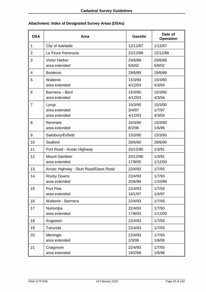
Cadastral Survey Guidelines
KNet 11757936 V3 February 2019 Page 53 of 163
Attachment: Index of Designated Survey Areas (DSAs)
DSA Area Gazette Date of
Operation
1 City of Adelaide 12/11/87 1/12/87
2 Le Fevre Peninsula 22/12/88 22/12/88
3 Victor Harbor
area extended
29/6/89
6/6/02
29/6/89
6/9/02
4 Booleroo 29/6/89 29/6/89
5 Waikerie
area extended
15/3/90
4/12/03
15/3/90
4/3/04
6 Barmera – Berri
area extended
15/3/90
4/12/03
15/3/90
4/3/04
7 Lyrup
area extended
area extended
15/3/90
3/4/97
4/12/03
15/3/90
1/7/97
4/3/04
8 Renmark
area extended
15/3/90
8/2/96
15/3/90
1/6/96
9 Salisbury/Enfield 15/3/90 15/3/90
10 Seaford 28/6/90 28/6/90
11 Port Road - Anzac Highway 20/12/90 1/3/91
12 Mount Gambier
area extended
20/12/90
17/8/00
1/3/91
1/12/00
13 Anzac Highway - Sturt Road/Daws Road 22/4/93 1/7/93
14 Roxby Downs
area extended
22/4/93
20/6/96
1/7/93
1/10/96
15 Port Pirie
area extended
22/4/93
16/1/97
1/7/93
1/4/97
16 Waikerie - Barmera 22/4/93 1/7/93
17 Nuriootpa
area extended
22/4/93
17/8/00
1/7/93
1/12/00
18 Angaston 22/4/93 1/7/93
19 Tanunda 22/4/93 1/7/93
20 Meningie
area extended
22/4/93
2/3/06
1/7/93
1/6/06
21 Craigmore
area extended
22/4/93
19/2/98
1/7/93
1/6/98
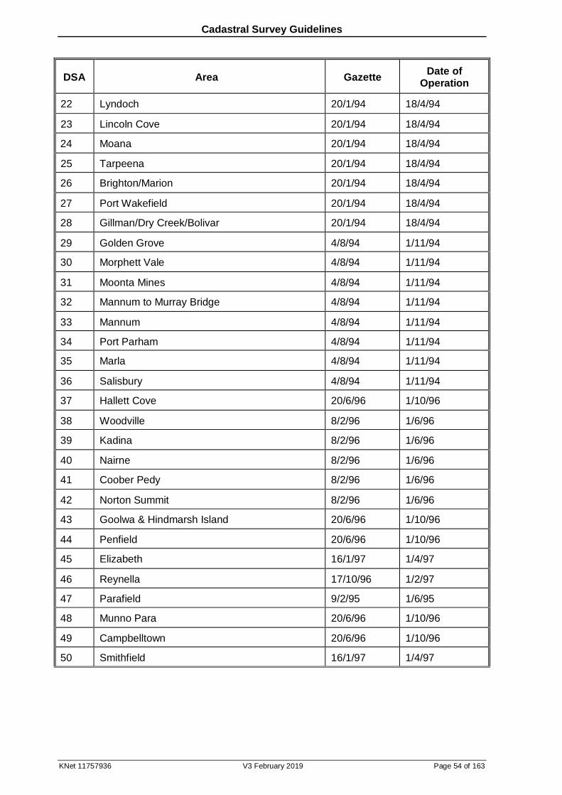
Cadastral Survey Guidelines
KNet 11757936 V3 February 2019 Page 54 of 163
DSA Area Gazette Date of
Operation
22 Lyndoch 20/1/94 18/4/94
23 Lincoln Cove 20/1/94 18/4/94
24 Moana 20/1/94 18/4/94
25 Tarpeena 20/1/94 18/4/94
26 Brighton/Marion 20/1/94 18/4/94
27 Port Wakefield 20/1/94 18/4/94
28 Gillman/Dry Creek/Bolivar 20/1/94 18/4/94
29 Golden Grove 4/8/94 1/11/94
30 Morphett Vale 4/8/94 1/11/94
31 Moonta Mines 4/8/94 1/11/94
32 Mannum to Murray Bridge 4/8/94 1/11/94
33 Mannum 4/8/94 1/11/94
34 Port Parham 4/8/94 1/11/94
35 Marla 4/8/94 1/11/94
36 Salisbury 4/8/94 1/11/94
37 Hallett Cove 20/6/96 1/10/96
38 Woodville 8/2/96 1/6/96
39 Kadina 8/2/96 1/6/96
40 Nairne 8/2/96 1/6/96
41 Coober Pedy 8/2/96 1/6/96
42 Norton Summit 8/2/96 1/6/96
43 Goolwa & Hindmarsh Island 20/6/96 1/10/96
44 Penfield 20/6/96 1/10/96
45 Elizabeth 16/1/97 1/4/97
46 Reynella 17/10/96 1/2/97
47 Parafield 9/2/95 1/6/95
48 Munno Para 20/6/96 1/10/96
49 Campbelltown 20/6/96 1/10/96
50 Smithfield 16/1/97 1/4/97

Cadastral Survey Guidelines
KNet 11757936 V3 February 2019 Page 55 of 163
DSA Area Gazette Date of
Operation
51 Bridgewater 17/10/96 1/2/97
52 Aberfoyle Park 3/4/97 1/7/97
53 Littlehampton 20/6/96 1/10/96
54 Jervois 17/10/96 1/2/97
55 Aldinga 18/9/97 18/12/97
56 Paralowie 3/4/97 1/7/97
57 Direk 3/4/97 1/7/97
58 Norwood 20/6/96 1/10/96
59 Murray Bridge 17/10/96 1/2/97
60 Buckland Park 17/10/96 1/2/97
61 Wirrina 7/9/95 7/12/95
62 Gawler 8/2/96 1/6/96
63 Port Hughes 17/10/96 1/2/97
64 Loxton 16/1/97 1/4/97
65 Mount Barker
area extended
16/1/97
3/9/09
1/4/97
3/12/09
66 Para Vista 18/9/97 18/12/97
67 Penola 3/4/97 1/7/97
68 Blanche Harbor 18/9/97 18/12/97
69 Stony Point 3/4/97 1/7/97
70 Fitzgerald Bay 3/4/97 1/7/97
71 Port Augusta 3/4/97 1/7/97
72 Craigburn Farm 17/10/96 1/2/97
73 Evanston 18/9/97 18/12/97
74 Saint Agnes 27/5/99 1/9/99
75 Malvern 18/9/97 18/12/97
76 Hahndorf 18/9/97 18/12/97
77 Loxton IA 18/9/97 18/12/97
78 Whyalla 19/2/98 1/6/98
79 Williamstown 19/2/98 1/6/98

Cadastral Survey Guidelines
KNet 11757936 V3 February 2019 Page 56 of 163
DSA Area Gazette Date of
Operation
80 Kersbrook 18/9/97 18/12/97
81 Mount Pleasant 18/9/97 18/12/97
82 Birdwood 19/2/98 1/6/98
83 Mount Torrens 19/2/98 1/6/98
84 Gumeracha 19/11/98 1/3/99
85 Macclesfield 19/2/98 1/6/98
86 Meadows 19/2/98 1/6/98
87 Echunga 19/2/98 1/6/98
88 Mount Compass
area extended
19/2/98
2/11/00
1/6/98
1/2/01
89 Fairview Park 27/5/99 1/9/99
90 Uraidla 27/5/99 1/9/99
91 Coffin Bay
area extended
19/2/98
15/7/04
1/6/98
15/10/04
92 Murninne Beach 19/2/98 1/6/98
93 Woodside 18/6/98 18/9/98
94 Saint Kilda 19/11/98 1/3/99
95 Virginia 19/11/98 1/3/99
96 Paringa 18/6/98 18/9/98
97 Highbury 27/5/99 1/9/99
98 Sunlands 27/5/99 1/9/99
99 Moorook 27/5/99 1/9/99
100 Port Lincoln
area extended
27/5/99
20/12/07
1/9/99
20/3/08
101 Balhannah 27/5/99 1/9/99
102 Oakbank 16/12/99 1/4/00
103 Streaky Bay 16/12/99 1/4/00
104 Rostrevor 2/11/00 1/2/01
105 Lobethal 16/12/99 1/4/00
106 Pyap 16/12/99 1/4/00
107 Wallaroo 16/12/99 1/4/00
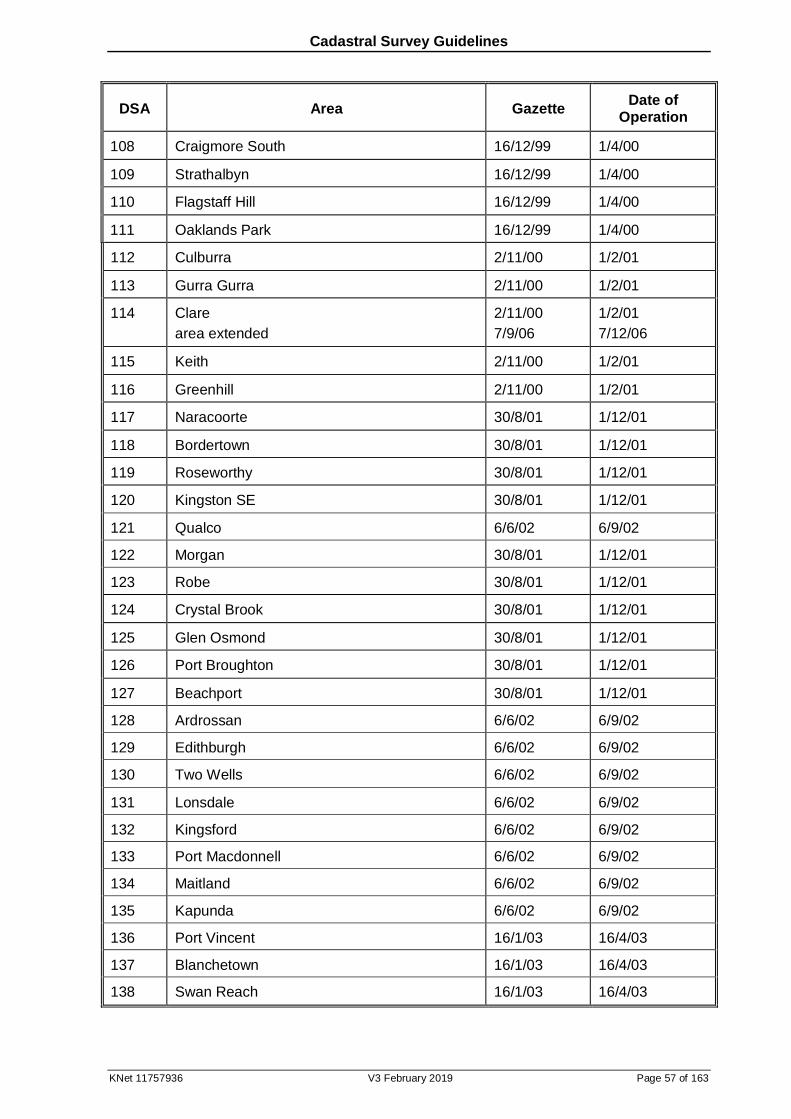
Cadastral Survey Guidelines
KNet 11757936 V3 February 2019 Page 57 of 163
DSA Area Gazette Date of
Operation
108 Craigmore South 16/12/99 1/4/00
109 Strathalbyn 16/12/99 1/4/00
110 Flagstaff Hill 16/12/99 1/4/00
111 Oaklands Park 16/12/99 1/4/00
112 Culburra 2/11/00 1/2/01
113 Gurra Gurra 2/11/00 1/2/01
114 Clare
area extended
2/11/00
7/9/06
1/2/01
7/12/06
115 Keith 2/11/00 1/2/01
116 Greenhill 2/11/00 1/2/01
117 Naracoorte 30/8/01 1/12/01
118 Bordertown 30/8/01 1/12/01
119 Roseworthy 30/8/01 1/12/01
120 Kingston SE 30/8/01 1/12/01
121 Qualco 6/6/02 6/9/02
122 Morgan 30/8/01 1/12/01
123 Robe 30/8/01 1/12/01
124 Crystal Brook 30/8/01 1/12/01
125 Glen Osmond 30/8/01 1/12/01
126 Port Broughton 30/8/01 1/12/01
127 Beachport 30/8/01 1/12/01
128 Ardrossan 6/6/02 6/9/02
129 Edithburgh 6/6/02 6/9/02
130 Two Wells 6/6/02 6/9/02
131 Lonsdale 6/6/02 6/9/02
132 Kingsford 6/6/02 6/9/02
133 Port Macdonnell 6/6/02 6/9/02
134 Maitland 6/6/02 6/9/02
135 Kapunda 6/6/02 6/9/02
136 Port Vincent 16/1/03 16/4/03
137 Blanchetown 16/1/03 16/4/03
138 Swan Reach 16/1/03 16/4/03
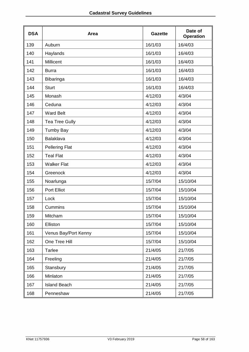
Cadastral Survey Guidelines
KNet 11757936 V3 February 2019 Page 58 of 163
DSA Area Gazette Date of
Operation
139 Auburn 16/1/03 16/4/03
140 Haylands 16/1/03 16/4/03
141 Millicent 16/1/03 16/4/03
142 Burra 16/1/03 16/4/03
143 Bibaringa 16/1/03 16/4/03
144 Sturt 16/1/03 16/4/03
145 Monash 4/12/03 4/3/04
146 Ceduna 4/12/03 4/3/04
147 Ward Belt 4/12/03 4/3/04
148 Tea Tree Gully 4/12/03 4/3/04
149 Tumby Bay 4/12/03 4/3/04
150 Balaklava 4/12/03 4/3/04
151 Pellering Flat 4/12/03 4/3/04
152 Teal Flat 4/12/03 4/3/04
153 Walker Flat 4/12/03 4/3/04
154 Greenock 4/12/03 4/3/04
155 Noarlunga 15/7/04 15/10/04
156 Port Elliot 15/7/04 15/10/04
157 Lock 15/7/04 15/10/04
158 Cummins 15/7/04 15/10/04
159 Mitcham 15/7/04 15/10/04
160 Elliston 15/7/04 15/10/04
161 Venus Bay/Port Kenny 15/7/04 15/10/04
162 One Tree Hill 15/7/04 15/10/04
163 Tarlee 21/4/05 21/7/05
164 Freeling 21/4/05 21/7/05
165 Stansbury 21/4/05 21/7/05
166 Minlaton 21/4/05 21/7/05
167 Island Beach 21/4/05 21/7/05
168 Penneshaw 21/4/05 21/7/05
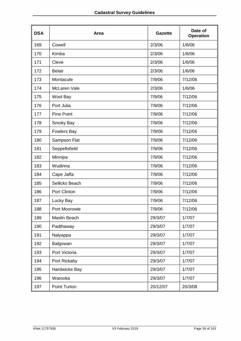
Cadastral Survey Guidelines
KNet 11757936 V3 February 2019 Page 59 of 163
DSA Area Gazette Date of
Operation
169 Cowell 2/3/06 1/6/06
170 Kimba 2/3/06 1/6/06
171 Cleve 2/3/06 1/6/06
172 Belair 2/3/06 1/6/06
173 Montacute 7/9/06 7/12/06
174 McLaren Vale 2/3/06 1/6/06
175 Wool Bay 7/9/06 7/12/06
176 Port Julia 7/9/06 7/12/06
177 Pine Point 7/9/06 7/12/06
178 Smoky Bay 7/9/06 7/12/06
179 Fowlers Bay 7/9/06 7/12/06
180 Sampson Flat 7/9/06 7/12/06
181 Seppeltsfield 7/9/06 7/12/06
182 Minnipa 7/9/06 7/12/06
183 Wudinna 7/9/06 7/12/06
184 Cape Jaffa 7/9/06 7/12/06
185 Sellicks Beach 7/9/06 7/12/06
186 Port Clinton 7/9/06 7/12/06
187 Lucky Bay 7/9/06 7/12/06
188 Port Moorowie 7/9/06 7/12/06
189 Maslin Beach 29/3/07 1/7/07
190 Padthaway 29/3/07 1/7/07
191 Nalyappa 29/3/07 1/7/07
192 Balgowan 29/3/07 1/7/07
193 Port Victoria 29/3/07 1/7/07
194 Port Rickaby 29/3/07 1/7/07
195 Hardwicke Bay 29/3/07 1/7/07
196 Warooka 29/3/07 1/7/07
197 Point Turton 20/12/07 20/3/08
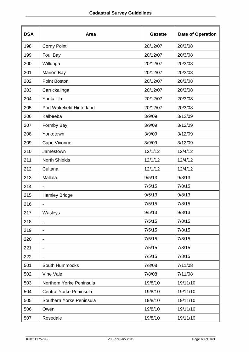
Cadastral Survey Guidelines
KNet 11757936 V3 February 2019 Page 60 of 163
DSA Area Gazette Date of Operation
198 Corny Point 20/12/07 20/3/08
199 Foul Bay 20/12/07 20/3/08
200 Willunga 20/12/07 20/3/08
201 Marion Bay 20/12/07 20/3/08
202 Point Boston 20/12/07 20/3/08
203 Carrickalinga 20/12/07 20/3/08
204 Yankalilla 20/12/07 20/3/08
205 Port Wakefield Hinterland 20/12/07 20/3/08
206 Kalbeeba 3/9/09 3/12/09
207 Formby Bay 3/9/09 3/12/09
208 Yorketown 3/9/09 3/12/09
209 Cape Vivonne 3/9/09 3/12/09
210 Jamestown 12/1/12 12/4/12
211 North Shields 12/1/12 12/4/12
212 Cultana 12/1/12 12/4/12
213 Mallala 9/5/13 9/8/13
214 - 7/5/15 7/8/15
215 Hamley Bridge 9/5/13 9/8/13
216 - 7/5/15 7/8/15
217 Wasleys 9/5/13 9/8/13
218 - 7/5/15 7/8/15
219 - 7/5/15 7/8/15
220 - 7/5/15 7/8/15
221 - 7/5/15 7/8/15
222 - 7/5/15 7/8/15
501 South Hummocks 7/8/08 7/11/08
502 Vine Vale 7/8/08 7/11/08
503 Northern Yorke Peninsula 19/8/10 19/11/10
504 Central Yorke Peninsula 19/8/10 19/11/10
505 Southern Yorke Peninsula 19/8/10 19/11/10
506 Owen 19/8/10 19/11/10
507 Rosedale 19/8/10 19/11/10
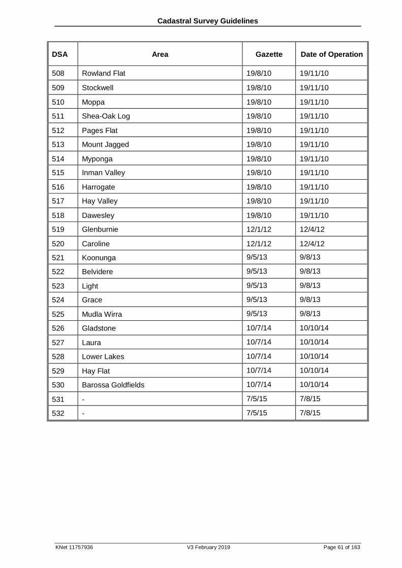
Cadastral Survey Guidelines
KNet 11757936 V3 February 2019 Page 61 of 163
DSA Area Gazette Date of Operation
508 Rowland Flat 19/8/10 19/11/10
509 Stockwell 19/8/10 19/11/10
510 Moppa 19/8/10 19/11/10
511 Shea-Oak Log 19/8/10 19/11/10
512 Pages Flat 19/8/10 19/11/10
513 Mount Jagged 19/8/10 19/11/10
514 Myponga 19/8/10 19/11/10
515 Inman Valley 19/8/10 19/11/10
516 Harrogate 19/8/10 19/11/10
517 Hay Valley 19/8/10 19/11/10
518 Dawesley 19/8/10 19/11/10
519 Glenburnie 12/1/12 12/4/12
520 Caroline 12/1/12 12/4/12
521 Koonunga 9/5/13 9/8/13
522 Belvidere 9/5/13 9/8/13
523 Light 9/5/13 9/8/13
524 Grace 9/5/13 9/8/13
525 Mudla Wirra 9/5/13 9/8/13
526 Gladstone 10/7/14 10/10/14
527 Laura 10/7/14 10/10/14
528 Lower Lakes 10/7/14 10/10/14
529 Hay Flat 10/7/14 10/10/14
530 Barossa Goldfields 10/7/14 10/10/14
531 - 7/5/15 7/8/15
532 - 7/5/15 7/8/15
Cadastral Survey Guidelines
KNet 11757936 V3 February 2019 Page 62 of 163
6 Confused Boundary Areas
6.1 Introduction
It has been recognised by surveyors in South Australia that there are many areas where:
there is long standing encroachment that is not localised but extends over general areas of significant numbers of allotments, and/or
the condition of the cadastre is such that common law redefinition of parcel boundaries is uncertain.
This has the potential to affect security of title, may cause financial and emotional hardship for owners, and uncertainty for surveyors.
Many reasons have been given for the poor quality of the cadastre in these areas, significant amongst these being:
the poor quality of the original survey,
original occupation of boundaries occurs long after marking gone,
boundaries being created and occupied without survey,
inadequate extent of redefinition surveys, or
redefinition surveys laying title data from unreliable start points contrary to other evidence.
The confused boundary provisions of the Survey Act 1992 and the Real Property Act 1886 were introduced in 1993 to relieve this hardship and uncertainty. In 2000 these Acts were amended to accommodate repealed provisions of s308-310 of the Local Government Act 1934.
If these statutory provisions are deemed appropriate for a particular area then a Confused Boundary Area (CBA) is declared. The role of the boundary surveyor working within a CBA is to determine the alignments of the boundaries in such manner as is equitable and to prepare an appropriate plan. Due consideration must be given to all relevant plans, occupations and other matters.
Parcel boundaries outside of areas declared a CBA must be reinstated in accord with common law principles (see section 4). Surveys in areas of boundary uncertainty can not benefit from the above statutory provisions until the area is included in a CBA declaration (see 6.3).
6.2 Controlling Legislation
Legislative authority for defining and carrying out surveys in CBAs is contained in s50 & 51 of the Survey Act 1992. They provide:
50—Confused Boundary Areas
(1) Subject to subsection (2), the Surveyor-General may, by notice in the Gazette declare that a specified area within the State is a Confused Boundary Area.
(1a) The Surveyor-General may make a declaration under subsection (1)-
(a) on the application of-
(i) the Registrar-General; or
(ii) the Commissioner for Highways; or
(iii) a council; or
(b) on his or her own motion.
(2) However, a declaration under subsection (1) may only be made if the Surveyor-General is satisfied that, generally, the occupation of land within the area does not accord to a
Cadastral Survey Guidelines
KNet 11757936 V3 February 2019 Page 63 of 163
substantial extent with the boundaries of land as shown in records or plans kept in the Lands Titles Registration Office.
(3) A notice under this section may be varied or revoked by subsequent notice in the Gazette.
51—Surveys within Confused Boundary Area
(1) Where a cadastral survey of land within a Confused Boundary Area is carried out by a surveyor, the boundaries of the land must (instead of being determined in accordance with accepted surveying practice and the provisions of this Act) be determined on the basis of what is fair and equitable having regard to-
(a) existing physical boundaries; and
(b) the length of time that those boundaries have departed from the boundaries as shown in any public records of survey or as marked by existing survey marks; and
(c) all other relevant factors.
(2) Where a plan of the boundaries of land within a Confused Boundary Area is lodged in the Lands Titles Registration Office, it must be accompanied by a statement that-
(a) sets out the basis on which the boundaries were determined; and
(b) is signed by the surveyor who certifies the plan.
(3) The Registrar-General must examine a plan lodged under subsection (2) and then forward a copy of the plan to the Surveyor-General for approval under this section.
(4) As soon as practicable after a plan of the boundaries of land within a Confused Boundary Area is forwarded to the Surveyor-General under this section, the Surveyor-General must give notice in accordance with this section-
(a) to all persons with a registered interest in the land; and
(b) to all persons with a registered interest in land adjoining the land; and
(c) to all other persons who have a registered interest in land that is likely, in the opinion of the Surveyor-General, to be directly or indirectly affected; and
(d) to the council for the area in which the land is situated.
(5) A notice under subsection (4)-
(a) must specify a place at which the plan may be viewed during normal office hours; and
(b) must specify a period (not less than 28 days after the date of the notice) within which objections relating to the determination of the land boundaries will be received by the Surveyor-General.
(5a) The Surveyor-General must, in considering any objections received under this section, consult with the Registrar-General.
(6) On consideration of a plan and any objections received under this section, the Surveyor-General may-
(a) approve the plan with or without modification; and
(b) carry out such further work as is necessary in view of the terms of the approval.
(7) The Surveyor-General must give notice of the terms of an approval and, if a plan is approved with modification, a brief description of the reasons for the decision as to those terms, to-
(a) the surveyor responsible for the survey; and
(b) all persons who were entitled to be notified under subsection (4) and who continue to hold the registered interest in land by reason of which they were so entitled; and
(c) all persons who have since the date of that notification acquired a registered interest in land by reason of which they would have been entitled to be notified if they had held that
Cadastral Survey Guidelines
KNet 11757936 V3 February 2019 Page 64 of 163
interest at that date.
(8) Any person entitled to receive a notice under subsection (7) may, within 14 days after receipt of the notice, appeal against the decision of the Surveyor-General to the Land and Valuation Court.
(9) The Land and Valuation Court may, on the hearing of an appeal, hear such evidence as it thinks fit, whether or not the evidence was produced before the Surveyor-General.
(10) The Land and Valuation Court may, on the hearing of an appeal, exercise any one or more of the following powers:
(a) affirm or vary the decision appealed against, or make in addition any decision that should have been made in the first instance;
(b) quash the decision appealed against and substitute any decision that should have been made in the first instance;
(c) remit the subject matter of the appeal to the Surveyor-General for further consideration;
(d) make any further or other order as to costs or any other matter that the case requires.
(11) If no appeal is lodged under this section against the approval of a plan by the Surveyor-General, the Registrar-General may deposit that plan in the Lands Titles Registration Office.
(12) If an appeal is lodged under this section and the Land and Valuation Court on appeal approves a plan, the Registrar- General may deposit that plan in the Lands Titles Registration Office.
(13) This section is in addition to and does not derogate from the Real Property Act 1886.
Associated statutory requirements dealing with CBAs are found in s255 of the Real Property Act 1886:
255—Confused boundaries
(1) A plan of the boundaries of land within a Confused Boundary Area that is lodged in the Lands Titles Registration Office under section 51(2) of the Survey Act 1992 must be accompanied by an application in a form approved by the Registrar-General.
(2) The Registrar-General must, on the lodging of a plan referred to in subsection (1), examine the plan as if it were a plan lodged under this Act.
(3) The Registrar-General may deposit a plan in the Lands Titles Registration Office pursuant to section 51 of the Survey Act 1992 without the consent of a person who appears from the Register Book to have or to claim an estate or interest in land affected by the plan.
(4) On the deposit of a plan referred to in subsection (3)-
(a) the boundaries of land affected by the plan are by force of this subsection altered to the extent necessary to give effect to the plan; and
(b) the Registrar-General may amend the original certificate of title, or may issue a new certificate of title, without the production of any duplicate or other instrument and without the consent of a person who appears to have or to claim an estate or interest in the land, and may amend any other relevant instrument or record; and
(c) if the Registrar-General so requires-any duplicate certificate of title or other instrument specified by the Registrar-General must be produced to the Registrar-General so that it can be amended or a new certificate issued.
(5) If the production of a certificate or other instrument is required under subsection (4), then, despite any agreement to the contrary, a person having possession of the certificate or other instrument is not entitled to demand or receive a fee or charge from any person for its production.
(6) Any amendment made to a certificate of title under this section will be taken to have been made prior to the registration of any instrument registered on the certificate.
Cadastral Survey Guidelines
KNet 11757936 V3 February 2019 Page 65 of 163
6.3 Identification & Declaration of Confused Boundary Areas
CBAs will be identified from two basic sources, these being the survey examiners of the Lands Titles Office (LTO) and practicing surveyors.
As a general rule, CBAs will not be declared unless it can be shown that a significant number of allotment boundaries in an area bounded by four roads or other suitable barrier do not accord with the occupation. Consistent differences between certificate of title and substantial occupations of the order of 0.4m are considered worthy of investigation.
The Crown Solicitor has advised the Surveyor-General against using confused boundary statutory provisions to resolve neighbourhood boundary disputes.
There are a number of pockets where localised discrepancies between occupation and title are found. Rather than declaring a CBA in these cases, if it is not desired to shift the occupation, conventional land division or correction to Title provisions should be used.
Once all boundaries within a CBA have been redefined the declaration will be revoked by gazettal (for reasons of practicality and administrative efficiency a CBA will generally have all its parcel boundaries reviewed at the same time). For the duration of the declaration a Rack Plan will be available on SAILIS indicating to surveyors the existence of the CBA.
6.4 Considerations in Determining Boundaries in CBAs
a. Fair & Equitable
The field component of a survey in a CBA will not vary from the standard survey requirements, except with regard to pegging (see 6.5). The same however can not be said for the principles of boundary redefinition as the legislation directs definitions to be determined ‘on the basis of what is fair and equitable’.
Occupations are prima facie evidence of the confines of the parcels, however this may need to be confirmed by consultation with the present registered proprietors or from the original documents establishing the boundaries. Generally, alignments determined and adjusted with a strong emphasis given to long standing occupations, within reasonable agreement with the existing records, will be the most equitable solution. This is so even where two allotments along a road frontage may suffer shortages while the remaining allotments enjoy an excess. In other words it may not prove equitable to recognise title data by standing off a number of occupations.
The definition of an ‘equitable’ boundary is a very subjective matter. Experiences from the “308” alignment survey program have been that the majority of property owners believe that their existing fences etc. mark the limit of their ownership, and that they are happy to have this reflected in their titles, even if the original dimensions are altered.
Within an area of boundary confusion there is a fine distinction between what constitutes an encroachment of structures onto the neighbour's property, and what is an equitable adjustment that includes improvements within the property. Quality and cost of occupations have a relationship with equitable positioning. It is more equitable to overthrow a poor quality fence in favour of title than a high cost wall.
Existing physical boundaries should not be the sole matter considered with regard to determination of the boundary position; regard should also be given to the plan position. ‘Plan’ position infers a reliable start point. By the nature of CBA surveys there is often no reliable start point. In these areas the best plan position may only be from some arbitrary start point which may not agree with other arbitrary start points or the road corner as originally pegged. In these cases plan position is logically only a first approximation which nevertheless enables comparison with occupation. Clarification may be sought from the Surveyor-General.
There may be cases where the adoption of occupation would not be considered equitable. Consider the case in a CBA where there is approximately data distance between the alignment of two road boundaries and the occupation marking the common rear boundary of
Cadastral Survey Guidelines
KNet 11757936 V3 February 2019 Page 66 of 163
two allotments is a considerable distance (say 2 metres) out of position. In such a case the occupation could hardly be accepted as an equitable boundary. In these instances both parties should be informed of the situation and encouraged to either accept the fence as the boundary or adopt title data. If agreement is not reached the boundary should be reinstated at its common law position (see also formal objection process at 6.5 below).
As a general guideline, the following should be considered in determining a fair and equitable boundary:
a. the occupation
b. the age of the occupation
c. the wishes of the property owners
d. previous survey history
e. certificate of title data, and
f. all other relevant factors
b. Steps & Bends
In establishing road alignment boundaries, surveyors should try to avoid:
steps along the allotment frontages. Steps should only be introduced at road corners,
bends on the road face of an allotment. Bends should only be introduced at allotment corners, and
encroachment of the alignment into the material of substantial stone or brick fences. Road alignments should be along the face of occupations where possible.
In deciding upon side and rear boundaries surveyors should consider the following:
wherever possible, keep within the framework of the physical occupation,
use bends and steps where necessary to protect substantial occupations,
give consideration to maintaining an orderly and practical boundary structure where occupation is not substantial,
while it may not be possible to adopt a line of fencing that avoids encroachment of eaves & gutters, these later features may be considered in determining equitable boundaries, and
while not required to protect encroaching service facilities, avoid creating such encroachments in the equitable determination of boundaries.
c. Easements
While the CBA plan cannot be used as a vehicle for creation or extinguishment of easements, resolution of confusion in easement boundaries may result in changes to their data.
6.5 Consultation, Objections & Alterations
Prior to declaration of a CBA the Surveyor-General will notify all survey firms of the area proposed with the aim of determining if redefinition surveys are in progress.
The existence of a CBA will be flagged to surveyors potentially working in the area by the
Cadastral Survey Guidelines
KNet 11757936 V3 February 2019 Page 67 of 163
Surveyor-General lodging a Rack Plan in the LTO17 and by arranging for Registrar-General’s note 52 on affected CTs.
Prior to survey all affected residents are to be advised (by letter drop) by the surveyor of the nature of work being done and the date of commencement. During the course of the survey residents should be consulted, particularly when there are occupation anomalies. It is important for the surveyor to be alert to mutual agreements or of disputes between neighbours.
The pegging18 of corners in a CBA defined on a plan lodged in the LTO may be delayed until after approval for data by the LTO19.
Under s51(4) of the Survey Act 1992 the Council and all persons with a registered interest in
the land, in land adjoining the land, and land likely in the opinion of the Surveyor-General to be directly or indirectly affected, are notified by a registered letter that the plan is open for inspection in the Surveyor-General's Office or at the Council, for a period of 28 days. These persons may make objections to the Surveyor-General relating to the determination of land boundaries.
Under s51(5a) of the Act the representations are considered by the Surveyor-General, in consultation with the Registrar-General, who informs the person making the representation, and any other persons affected, of the action taken. Subsequent alterations to the plan require re-acceptance of the plan by the LTO.
Following expiration of the objection period the surveyor may be consulted by the Surveyor-General and if necessary required to make alterations to the plan. The role of the Surveyor-General, as an impartial arbiter in the determination of equitable solutions of boundary alignments, is provided in s51(6) of the Act.
Under s51(7) of the Act the Surveyor-General then advises the surveyor responsible for the survey and all those required to be notified under s 51(4), allowing for changes in registered interests since notification, of the plan’s terms of approval or modification and reasons for the decision as to those terms. In effect, the Surveyor-General determines the position of the boundary alignments20. These may differ from those determined by the surveyor.
Under s51(8) of the Act fourteen days is allowed for objection to the Land and Valuation Division of the Supreme Court with respect to this approved or modified plan. Ultimately it may be the Court that has the final say in the position of boundaries.
17 Where the survey reveals no change in the alignments, and road widths can be maintained such that the CBA survey is not proceeded with, the survey effort should be made available by lodgement of a Plan for Information Purposes. 18 CBA surveys result in the creation of new boundaries in lieu of old ones. As such, all boundaries whether road, side or rear must be marked in accordance with SGD 2. Note, particularly, that it is not necessary to mark corners within one metre of occupation shown on the plan. See also section 14. 19 S51(2)(a) requires that a report is lodged with a plan defining boundaries in a CBA. The report should follow the guidelines set out in section 17 and in addition provide reasons for the positions of the boundaries. 20 An objection from any person with a registered interest is therefore lodged against the boundary alignments determined by the Surveyor-General.
Cadastral Survey Guidelines
KNet 11757936 V3 February 2019 Page 68 of 163
7 Occupation
7.1 Introduction
The purpose of this section is to provide guidance in locating and describing occupation on boundary redefinition surveys. Boundary reinstatement in areas of lost and confused boundaries depends on the evidence provided by the physical occupation of land parcels. As such it is important that surveyors collect and demonstrate relevant information regarding this evidence.
Surveyors are also required to show occupation on plans for reasons other than boundary redefinition; information required may vary. The guidelines provided herein are the minimum; as always surveyors are encouraged to provide extra information wherever it will assist plan users.
Occupation is referred to in other sections, however, this section focuses on the occupation itself. See the following sections for related occupation guidance:
PPG section 7.65 for occupation requirement adjacent to subject land boundaries,
PPG sections 7.60 & 7.66 – 7.68 for plan presentation aspects,
Section 4.9 for the use of occupation as boundary redefinition evidence,
Section 11.3c for historical adoption of occupation in boundary creation,
Section 13.4 for accuracy, and
Section 15 for connection.
7.2 Controlling Legislation
Survey Regulations 2007:
11 – Survey evidence
(2) A surveyor must, in carrying out a cadastral survey-
(a) locate all existing survey marks, reference marks, improvements and natural features likely to provide evidence of the boundaries of the land; and
(b) connect the survey to all existing surveys of land in the vicinity likely to provide evidence of the boundaries of land by-
(ii) if there are not 2 apparently sound survey marks or reference marks to which the survey may be connected - by connecting to such apparently sound survey marks as are available and to improvements in a manner that enables the existing survey to be re-established; and
(c) if significant differences in the data from an existing survey are revealed - carry out such further work as may be necessary to establish whether or not the difference results from an error in measurement in the existing survey, the placement or acceptance of the survey mark in the existing survey or the siting of the improvement.
Cadastral Survey Guidelines
KNet 11757936 V3 February 2019 Page 69 of 163
7.3 Requirement for Occupation Information
Surveyors are required to show occupation information for one or more of the following reasons:
a demonstration to plan users of boundary redefinition evidence,
b demonstration to plan users of physical status of subject land boundaries surveyed, and/or
c to assist future surveyors in relocation of PSMs connected.
While surveyors are free to show information about occupation that does not fall into one of these categories, there is no requirement for them to do so. For example, there may be no need to show occupation adjacent to a boundary outside the subject land if that boundary was redefined from survey marks.
Where there is no occupation adjacent to boundaries or reference marks as described in a-c above then this fact should be noted21. The use of general notes such as “no occupation unless otherwise shown” should be used with care as they will be interpreted to cover boundaries surveyed, or reference marks connected, as described in a-c above.
PSMs must be related to occupation or other physical features unless all three of the following PSM conditions are met:
previously connected to the cadastre,
in an urban area, and
obvious on the ground, for example, plaque in concrete, or covered (with PSM cover; not buried).
7.4 Location Point
Note that the wave symbol is used to avoid having to describe a fence as ‘corrugated’. It is not intended to indicate that the offset necessarily refers to the centre of the cladding. Note however, that the symbol is generally utilised for this dual purpose in the case of the face of the corrugation being on the road alignment (see PPG Figure 7.28). Annotate the plan if felt necessary.
Measurement to occupation at different times will naturally result in a different position if the occupation develops a lean. This difference may be minimised by measuring as close to ground level as possible. Note that rural strainer posts may pivot about a point below ground level (or shift laterally) due to wire tension. The general lines of fencing leading from them may indicate this.
If connected as boundary redefinition evidence the point shown should be the one that best represents where the fence was erected. For example, a post pulled off the general line of fencing by wire tension would not represent this point. Conversely, intersections of fence lines on shallow bends may be misleading due to the large positional shift of the intersection along the fence line caused by a relatively small error in alignment. While the post may have shifted laterally, it may still be the best indicator of the longitudinal position of the original bend.
Buildings with projections such as plinths may be somewhat ambiguous as boundary evidence. Furthermore, building location symbols on previous plans may be ambiguous
21 There is an exception for plans preceded by outer boundary surveys. See PPG 7.65.2.
Cadastral Survey Guidelines
KNet 11757936 V3 February 2019 Page 70 of 163
unless these projections or others such as exposed footings have been labelled. Further compounding of confusion may be avoided by labelling the point located. It may be helpful in cases of uncertainty to locate both the plinth and the main wall.
As dividing fences are expected to straddle boundaries, subject to the below exceptions, they are presumed to be centrally located. With occupation connected for redefinition evidence there may be no certainty as to what part of a fence was erected on the original line of pegs, or previous fences. The centre of the bottom rail of the fence is recommended as it represents the centre of the corridor occupied by the fencing construction. A note describing the point located may be helpful to plan users. Exceptions to locating occupation at its centre include:
a. Road Alignments
Landowners should erect fencing entirely within their own parcel, not encroaching on the road. The relevant point to relate to the boundary is therefore the road face of the occupation. On the other hand this presumption does not apply to rural post and wire fences where traditionally it appears to have been acceptable for fences to straddle road boundaries.
b. Parapet Walls
Because the entire building is expected to be within the parcel, the face of the wall is presumed to be the point shown. This will normally be confirmed by the wall symbol used. Furthermore, many masonry fences with one face colinear with a building parapet wall appear to have been intended to be erected entirely within one parcel. As such, consideration should be given to showing the relevant face of this occupation rather than the centre22.
c. Retaining Walls
Generally retaining walls should be erected entirely within the land parcel benefitting from the earth retention. Where the wall is retaining fill on a parcel then it should have been erected entirely on that parcel. Where the wall was necessary to retain an earth face exposed through cut then it should have been erected on the cut parcel. Accordingly, the relevant face, not centre, of the wall should be located depending on whether it is retaining as a result of cut or fill.
7.5 Description
Description of occupation is particularly important where it is connected for the purpose of boundary redefinition evidence. Surveyors are encouraged to annotate individual pieces of occupation to provide any helpful information. It may not be as important to describe occupation located for other reasons.
The main aim in dating occupation is to relate its age to that of boundary creation. It is often difficult however to determine the former. Once a fence matures beyond about 30 years subjective estimates may be decades from the truth. In the absence of certainty the next best is an indication of the relative ages of occupation evidence within a survey. Some surveyors do this by assigning explicit ages such as “10 y.o.” or “100 y.o.”; others by more general indications such as “recent” or “very old”. There is no prescription as to what number of years constitute these more general categories. Typically though, occupation described as:
22 The width for these walls should be recorded in field notes as later assessment may suggest the centre should instead be the point shown on the plan.
Cadastral Survey Guidelines
KNet 11757936 V3 February 2019 Page 71 of 163
“new” or “recent” would not be more than 10 years old,
“old” would be a vintage of around 50 years. “Old” should not be used to describe occupation of less than 30 years age, and
“very old” would be a vintage of more than about 70 years. “Very old” should not be used to describe occupation of less than 50 years age.
The presumption is that occupation shown for the purpose of boundary redefinition evidence that is not described by age is neither old nor new.
Physical evidence of decayed occupation should be appropriately described, for example, “remains”. This qualifies normal occupation symbols, as this evidence may not be obvious, especially if there is newer occupation nearby. Post holes/butts are valuable rural evidence and can occasionally be found by careful inspection adjacent to more recent fence lines or strainer posts.
All other factors being equal, occupations of a more substantial nature generally have more care taken in the position they are erected. Any comments or symbols to indicate the nature of the occupation are therefore helpful.
7.6 Miscellaneous
a. Reliability
In cadastral surveys positional gross errors occur more frequently with occupation than marks, suggesting that occupation is perceived to be of lesser consequence, and is therefore subject to less final checking. In these cases it would be preferable to not show the occupation rather than be lax in connecting to it and showing it incorrectly. However, plan users have every right to assume that only the occupation commented on was considered in evaluation of evidence.
Where the centre of a fence is shown on the boundary it is expected that the boundary at that point in fact passes through some part of the width of the materials forming the fence construction. Where the face of a fence is shown on the boundary it is expected that the positional accuracy tolerances (See section 13.4) be satisfied. Irregular occupation should be noted as such to qualify offsets provided.
b. Intermediate Occupations
Occupation adjacent to subject land boundaries, between bends, must not be overlooked:
encroaching walls,
walls/gutters on or near the boundary, and
significant bends or steps in the occupation.
Where new corners are created along existing alignments, occupation of the existing alignment must be shown at the new corner (as well as the occupation of the new boundary).
c. Demolished & Copied Occupation
Occasionally occupation located by a surveyor is demolished prior to plan lodgement. It may be helpful to plan users to indicate this by way of a note adjacent to the occupation symbol.

Cadastral Survey Guidelines
KNet 11757936 V3 February 2019 Page 72 of 163
Surveyors may utilise the position of occupation evidence, now gone, shown on another surveyor’s plan. The gone position may be connected by tieline, however to avoid confusion the occupation symbol must not be used23.
It is unacceptable for a surveyor to show the position of existing occupation unless they have surveyed it; the position recorded by a previous survey must not be represented as if it has been surveyed.
23 This includes occupation adopted in old surveys in creation of Section boundaries (see section 11.3c). Little of this occupation remains however the traverse lines may be reconstructed. Theoretically there is a bend at every offset (unless three or more successive offsets are the same). In practice, it is considered acceptable in most cases to straighten out minor bends at the surveyor’s discretion. Given inherent uncertainties in the traverse reconstruction,
rounding off in the original survey, and allowable tolerances, a line of best fit that deviates to the order of one link from any of the theoretical bends may be acceptable.
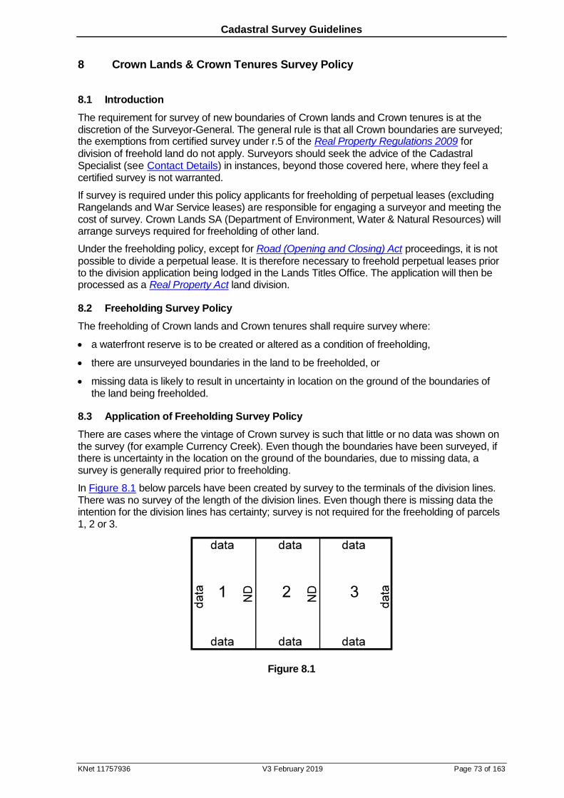
Cadastral Survey Guidelines
KNet 11757936 V3 February 2019 Page 73 of 163
8 Crown Lands & Crown Tenures Survey Policy
8.1 Introduction
The requirement for survey of new boundaries of Crown lands and Crown tenures is at the discretion of the Surveyor-General. The general rule is that all Crown boundaries are surveyed; the exemptions from certified survey under r.5 of the Real Property Regulations 2009 for
division of freehold land do not apply. Surveyors should seek the advice of the Cadastral Specialist (see Contact Details) in instances, beyond those covered here, where they feel a certified survey is not warranted.
If survey is required under this policy applicants for freeholding of perpetual leases (excluding Rangelands and War Service leases) are responsible for engaging a surveyor and meeting the cost of survey. Crown Lands SA (Department of Environment, Water & Natural Resources) will arrange surveys required for freeholding of other land.
Under the freeholding policy, except for Road (Opening and Closing) Act proceedings, it is not
possible to divide a perpetual lease. It is therefore necessary to freehold perpetual leases prior to the division application being lodged in the Lands Titles Office. The application will then be processed as a Real Property Act land division.
8.2 Freeholding Survey Policy
The freeholding of Crown lands and Crown tenures shall require survey where:
a waterfront reserve is to be created or altered as a condition of freeholding,
there are unsurveyed boundaries in the land to be freeholded, or
missing data is likely to result in uncertainty in location on the ground of the boundaries of the land being freeholded.
8.3 Application of Freeholding Survey Policy
There are cases where the vintage of Crown survey is such that little or no data was shown on the survey (for example Currency Creek). Even though the boundaries have been surveyed, if there is uncertainty in the location on the ground of the boundaries, due to missing data, a survey is generally required prior to freeholding.
In Figure 8.1 below parcels have been created by survey to the terminals of the division lines. There was no survey of the length of the division lines. Even though there is missing data the intention for the division lines has certainty; survey is not required for the freeholding of parcels 1, 2 or 3.
Figure 8.1
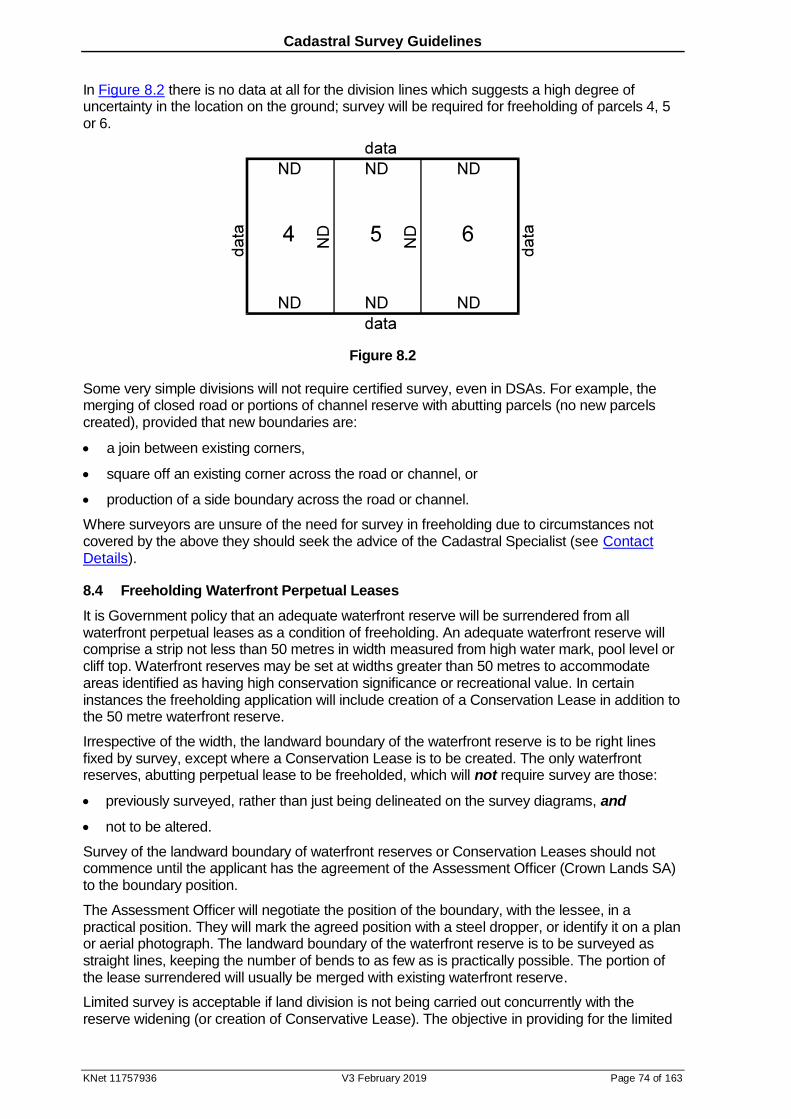
Cadastral Survey Guidelines
KNet 11757936 V3 February 2019 Page 74 of 163
In Figure 8.2 there is no data at all for the division lines which suggests a high degree of uncertainty in the location on the ground; survey will be required for freeholding of parcels 4, 5 or 6.
Figure 8.2
Some very simple divisions will not require certified survey, even in DSAs. For example, the merging of closed road or portions of channel reserve with abutting parcels (no new parcels created), provided that new boundaries are:
a join between existing corners,
square off an existing corner across the road or channel, or
production of a side boundary across the road or channel.
Where surveyors are unsure of the need for survey in freeholding due to circumstances not covered by the above they should seek the advice of the Cadastral Specialist (see Contact Details).
8.4 Freeholding Waterfront Perpetual Leases
It is Government policy that an adequate waterfront reserve will be surrendered from all waterfront perpetual leases as a condition of freeholding. An adequate waterfront reserve will comprise a strip not less than 50 metres in width measured from high water mark, pool level or cliff top. Waterfront reserves may be set at widths greater than 50 metres to accommodate areas identified as having high conservation significance or recreational value. In certain instances the freeholding application will include creation of a Conservation Lease in addition to the 50 metre waterfront reserve.
Irrespective of the width, the landward boundary of the waterfront reserve is to be right lines fixed by survey, except where a Conservation Lease is to be created. The only waterfront reserves, abutting perpetual lease to be freeholded, which will not require survey are those:
previously surveyed, rather than just being delineated on the survey diagrams, and
not to be altered.
Survey of the landward boundary of waterfront reserves or Conservation Leases should not commence until the applicant has the agreement of the Assessment Officer (Crown Lands SA) to the boundary position.
The Assessment Officer will negotiate the position of the boundary, with the lessee, in a practical position. They will mark the agreed position with a steel dropper, or identify it on a plan or aerial photograph. The landward boundary of the waterfront reserve is to be surveyed as straight lines, keeping the number of bends to as few as is practically possible. The portion of the lease surrendered will usually be merged with existing waterfront reserve.
Limited survey is acceptable if land division is not being carried out concurrently with the reserve widening (or creation of Conservative Lease). The objective in providing for the limited
Cadastral Survey Guidelines
KNet 11757936 V3 February 2019 Page 75 of 163
survey option is to reduce costs by not requiring existing boundaries to be redefined. The new waterfront boundary must be surveyed; it is not necessary to define its intersection with existing boundaries; however, the waterfront boundary must be connected to geodetic control.
Limited survey is intended for large leases with significant coastal frontage and no modern survey data. Limited survey cost savings may be insignificant outside these criteria; a conventional survey may be more applicable in freeholding smaller leases along the River Murray.
a. Limited Survey Conditions
The following conditions apply to the use of these limited surveys:
1. the survey must connect at its extremities to the geodetic control network through PSMs with PU<0.1m,
2. survey marks defining the cadastre in the immediate locality of the survey must be connected,
3. bends in the waterfront reserve boundary must be pegged,
4. steel droppers may be placed in lieu of PSMs at the required spacings (must not exceed 3000m; see section 14.3b2) along the waterfront reserve boundary (these droppers are not classed as PSMs; however, as a concession to placing of PSMs they will be required in DSAs). The droppers must be at least 450mm long and driven below ground surface.
5. conventional PSMs must be placed on the production of the waterfront boundary at the extremities of the survey.
6. to avoid possible confusion between the position of the waterfront reserve and existing Section boundaries, bends in the waterfront boundary should be no closer than 30m from the intersection of a fenced Section boundary and the new waterfront boundary.
7. it will not be necessary to mark the new boundary with datum pegs unless required by the lessee for fencing/identification purposes.
b. Limited Survey Plan Presentation
These limited surveys require modified plan presentation:
1. distances are not shown for undefined existing boundaries intersecting the new boundary.
2. distances along new boundaries that intersect undefined existing boundaries will be shown as:
‘all’ distance between bends in the new boundary, or
‘to PM’ distance between a bend and a PSM (see point 5 above).
3. bearings of the new and existing boundaries may not reflect the true relationship as the former will be oriented to MGA while the latter, being copied, may not (see PPG section 7.71).
4. connection to the surrounding geodetic control must be shown on the plan; however, if the geodetic control PSMs are not adjacent to the survey they need not be plotted. Instead, their connection to the PSMs at the extremities of the waterfront reserve may be shown in a schedule.
5. steel droppers, placed in lieu of PSMs, are not to be shown as PSMs. They are to be shown in the reference mark schedule as “DPR”. The plan symbol is a three-pronged star, or a solid circle.
6. PSMs placed on the production of new boundaries are to be shown in the reference mark schedule; the corner number will also refer to the PSM. This means that a dash is to be used in their reference bearing and distance fields.
7. parcel areas will be shown as approximate.

Cadastral Survey Guidelines
KNet 11757936 V3 February 2019 Page 76 of 163
c. Conservation Leases
Conservation Leases may be offered to lessees over land between the required freehold boundary and the 50m waterfront reserve. In these cases it is not necessary to survey that portion of the 50m reserve adjoining the area to be created as a Conservation Lease. This portion of the 50m reserve will therefore not be a right line boundary, but defined as a curvilinear boundary. The limited survey requirements outlined in ‘a’ and ‘b’ above may also apply if existing boundaries are not to be redefined.
In Figure 8.3 allotment 24 will be issued as a Conservation Lease. The boundary between allotment 24 and the coastal reserve (allotment 23) is 50m from the current MHWM. The position of the adjacent MHWM must be determined by survey or from the most recent aerial photograph. If the former: location measurements must be shown (PPG rule 19.2.2) in a schedule, or the latter: aerial photo reference information is included in the plan as shown on the example (Figure 8.3).
8.5 Pastoral Leases
Land may be transferred between pastoral leases through limited certified survey whereby:
a. there is no need to redefine existing unsurveyed boundaries.
b. techniques capable of ensuring relative and positional accuracy to better than 15 metres24 are adequate
c. where survey is outside conventional rural tolerances (see section 13.4) a plan note is required specifying the maximum relative and positional error, and the lines/corners this applies to (the technique may also be noted); for example: “Corners 3 ─ 34, inclusive, fixed by autonomous GPS to an accuracy better than 10 metres.”
d. PSMs are not required.
e. new boundary corners are defined by coordinates (specifying datum and zone) shown in a plan schedule (boundary bearings & distances not required).
8.6 National Parks in Pastoral Areas
The above relaxation in accuracy and marking requirements does not apply to the creation of new boundaries of National Parks in pastoral areas. While the survey of National Park boundaries should meet rural tolerances, their boundaries may be presented as corner coordinates referenced to quoted PSM coordinates. See Figure 8.4 for an example of their boundary data and PSM connection presentation.
It is strongly recommended that any proposed fencing precede survey.
24 Note that delineating boundaries from autonomous GNSS readings constitutes a cadastral survey under the Survey
Act 1992; requiring compliance with section 15 of that Act.
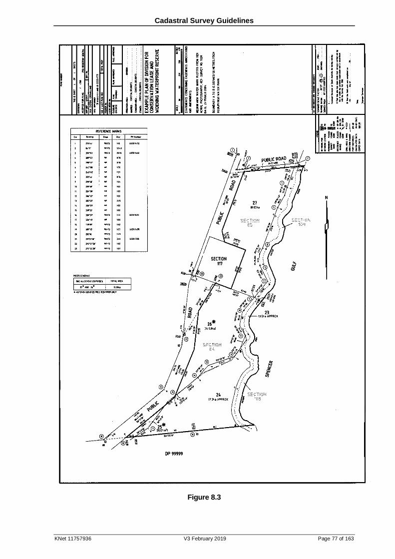
Cadastral Survey Guidelines
KNet 11757936 V3 February 2019 Page 77 of 163
Figure 8.3
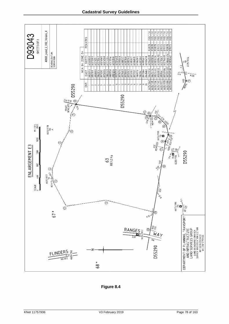
Cadastral Survey Guidelines
KNet 11757936 V3 February 2019 Page 78 of 163
Figure 8.4
Cadastral Survey Guidelines
KNet 11757936 V3 February 2019 Page 79 of 163
9 Searching
9.1 Introduction
It is obvious that the most careful and thorough survey can result in an invalid reinstatement of boundaries, and much rework, for the want of a plan missed in the search.
This section is not intended as a manual for searching systems. Rather, it will direct users to the systems available; detailed operation will require reference to on-line help files and tutorials or Land Services SA (LSSA) (see Contact Details).
Certain information is freely available from the Property Location Browser (PLB) and the map
viewer should be used as the primary source for survey mark searches; however, the primary source of title and survey plan information is the South Australian Integrated Land Information System (SAILIS). Members of the South Australian Land Administration Industry that have an ABN may become account holders by completing the required Application Form. SAILIS can
also be accessed by public customers with information paid for via credit card.
The following original records have been archived by State Records:
Dealings 1 – 362,091
Survey Office Diagram Books
Imperial and metric titles
Access the State Records Research Centre website for opening hours and details on ordering and viewing records.
Other original records are stored by LSSA and can be ordered in SAILIS and viewed on the
ground floor, 101 Grenfell Street, Adelaide, open from 9am to 5pm, Monday to Friday; turnaround time for orders is 72 hours.
Additional search information may be available by visiting the LSSA Information Counter, also on the ground floor.
Searching is also available using the public access monitors in the self-help area adjacent the Information Counter. Prints ordered from these monitors that are charged to accounts, or free of charge, may be collected from adjacent printers in the self-help area; prints to be paid for are collected at the Information Counter. Remotely ordered prints may be emailed, or picked up from the Information Counter.
Public searching is also available at the Old System Unit, phone (08) 8423 5059, 9:00am – 4:00pm Monday to Friday.
All enquiries relating to LSSA products and services should be directed to LSSA (see Contact Details).
9.2 Controlling Legislation
Legislative requirement for adequate search of records relevant to cadastral surveys is expressed in Survey Regulations 2007:
11 - Survey evidence
(1) A surveyor must, before carrying out a cadastral survey, obtain all information -
(a) that is likely to provide evidence of the boundaries of the land to be surveyed; and
(b) that is reasonably accessible.
Cadastral Survey Guidelines
KNet 11757936 V3 February 2019 Page 80 of 163
9.3 Title Searching
a. Title Indices
Title references may be determined from PLB or SAILIS using information such as plan/parcel
number, address or valuation number.
PLB delivers a current view of the State’s land parcels and provides key identifiers such as plan/parcel identifier and CT reference. By selecting properties on the map, users can link directly to SAILIS to purchase specific property details.
Land Services SA accepts the PLB as providing the authoritative source of information for road names, abuttals, localities etc required on plans and surveys. Surveyors and plan drafters are strongly encouraged to use the PLB for this information.
SAILIS may be used to determine parent Title references back to the last manual Title. A break
in the chain of manual Titles may be overcome by reference to:
the transfer under which the Title issued,
the Property Books, or
Plots (see 9.4b below).
The Property Books are available in SAILIS or can be viewed on the public access monitors located on the ground floor, 101 Grenfell Street. These Books list the Titles issued when parcels of land were first brought under the Real Property Act by either Land Grant or
Application (in which case the Application number is also listed).
Search enquiries should be directed to the Old System Unit, phone (08) 8423 5059, 9:00am – 4:00pm Monday to Friday, where it appears land is not under the provisions of the Real Property Act.
Occasionally Sections that apparently have become public road require confirmation of their dedication:
1. the reference to the cancelled Crown Record (CR) may be determined in SAILIS
2. viewing the CR in SAILIS, returns the dealing number,
3. the dealing (see 9.3b) should confirm dedication for road purposes and/or include a copy of the gazettal.
b. Accessing Manual Titles & Dealings
Manual Titles have been scanned and are available for viewing and download in SAILIS; they
may also be viewed on the public access monitors located in the self-help area on the ground floor, 101 Grenfell Street. Note that a very small percentage of manual Titles are still current or only partially cancelled. See SAILIS.
Dealings 1 – 2,800,000 have not been scanned or microfilmed. These may be ordered in SAILIS or at the ground floor Information Counter, 101 Grenfell Street. Early Transfers up to
362091 are stored by State Records. Access the State Records Research Centre website for opening hours and details on ordering and viewing records.
Dealings 2,800,001 onwards have been microfilmed or scanned and are available in SAILIS.
There are many exceptions however the transition from microfilming to scanning is around number 7,800,000. Where a dealing enquiry above 2,800,000 shows “no record” for the scanned image it should be available on microfilm.
Microfilms may be viewed at no cost in the self-help area on the ground floor, 101 Grenfell Street. A self-help terminal adjacent to the microfilm cartridge area directs the user to the appropriate cartridge/frame.
Surveyors may arrange, at the discretion of the Old Systems Unit (see Contact Details), to search Applications for potential survey plans (not indexed) at the Netley site. Otherwise, Section 42 of the Real Property Act 1886 restricts production of documents supporting
Cadastral Survey Guidelines
KNet 11757936 V3 February 2019 Page 81 of 163
applications to bring land under the Act; production requires a written order of the applicant, or person claiming through or under them, or Court order.
Crown Leases are available in SAILIS and can be viewed on the public access monitors
located on the ground floor, 101 Grenfell Street.
Public Maps (see section 19.2) are available for viewing on aperture cards.
9.4 Survey Searching
SAILIS contains the three main indices of survey plans:
Survey Mark search
Survey Graphic Index
Crown Parcel search
No one index can be relied on to provide all appropriate plan references. In urban areas, it is necessary to utilise, at least, the Survey Mark search and Survey Graphic Index; in rural areas the Survey Mark search and Crown Parcel search should be used as a minimum (see below under their individual headings).
It is prudent to exercise care in searching to ensure that all surveys that may affect the subject land are considered. This may, in some instances, involve searching the title register from the original title (see 9.3 above) to determine when a change in title data occurred. Examination of the associated dealings responsible for the change in title data should disclose the presence of a survey plan or refer to another dealing containing it. In particular, Application surveys should be searched and considered as evidence where there is a lack of modern surveys redefining adjacent boundaries (see reference to Property Books in 9.3 above).
Search of more obscure sources may require the services of an experienced searcher or enquiries at the Information Counter, 101 Grenfell Street. These sources are described in Survey Searching Guide.
Survey plan images may be viewed, downloaded and printed through SAILIS within 24 hours of
lodgement. Unapproved plan images (clearly labelled as such) will remain on the system until deposit or acceptance for filing, at which time the plan image will be replaced with the final plan.
Images of plans not available on SAILIS may be ordered at the Information Counter, 101 Grenfell Street or through SAILIS.
Errors in SAILIS searches and other queries relating to SAILIS should be directed to [email protected].
a. Survey Mark Search
The Survey Mark Search is a fee free function within PLB & SAILIS that provides information about permanent survey marks (PSMs) and other survey marks by reference to their unique identification number25. PLB should be used as the primary search tool for PSM mark details;
the location and identity of survey marks may be obtained graphically by reference to the Survey Marks layer. SAILIS is the primary source for plan details.
If difficulty is encountered with the survey mark number as shown on the Survey Marks layer of PLB contact the Survey Data Officer, Survey Operations (see Contact Details).
25 Note the CSV files of information searched may be downloaded for processing in other systems. These files can be viewed using Excel.
Cadastral Survey Guidelines
KNet 11757936 V3 February 2019 Page 82 of 163
The following information is available for survey marks via the Survey Mark Search:
Plan Details:
references to surveys which connect to PSMs,
references to visits to PSMs which do not involve connection, and
PSM gone references.
On some connections/visits PSMs may also be covered or reconstructed, or converted from a reference mark. Most of the non-cadastral references relate to mark maintenance and tertiary network projects carried out by the Surveyor-General’s staff or contractors.
Some survey references are in the form of search or docket numbers. The appropriate plan reference may be found through a SAILIS Cross Reference enquiry (see 9.4d1 below).
Diagram Book Page (DBP, also referred to as Survey Office Diagrams) references specify a Hundred code & name. The Hundred name may be determined from a list of these codes in Survey Searching Guide
The Survey Mark Search cannot be relied on as the only searching tool for cadastral
surveys as:
PSMs not connected since the commencement of the PSM records (about 1950) may not be on PLB,
plans of surveys that did not connect to PSMs are not recorded, and
computer based recording of plan references was not commenced until the early 1970s. Before this plan references were recorded on the back of PM Cards (locality plans, see 9.4d5 below). Not all of these plan references are available using the Survey Mark Search.
Mark Details:
horizontal coordinates,
heights,
positional uncertainty (PU), and
mark type, status & cross referencing.
For explanation of the Mark Details codes see Survey Mark Search Code Descriptions
Problems with survey accurate coordinates or elevations should be reported using the online coordinate error report form.
Errors in the spatial datasets (layers), including the spatial representation of PSMs, of the Property Location Browser (PLB) should be reported using the online spatial data error report
form.
b. Survey Graphic Index
The Survey Graphic Index is based on 1:2500 and 1:10,000 standard map sheets, and some Hundred plans and special sheets. It is concentrated in urban and urban fringe areas.
Update ceased at DP 65000 and FP 46000. Images of these map sheets are available as a plan type in SAILIS (no charge to print). There are generally two images for each plan. One image is a map on which is plotted circled numbers representing the approximate locations of surveys. The second image references the circled number to the cadastral plan number.
The Survey Graphic Index cannot be relied on as the only searching tool for cadastral surveys
as:
the freehold survey index books, from which the Survey Graphic Index was compiled, were
not commenced until the early 1940s, so freehold surveys prior to then may not have been indexed,
Cadastral Survey Guidelines
KNet 11757936 V3 February 2019 Page 83 of 163
plans found attached to Applications, Dockets and documents (see section 9.4d1 below) were only indexed if discovered since the early 1980s,
subdivisions are not included,
Crown surveys prior to 1987 are not included, and
update ceased in 2004.
The freehold survey index books used Section numbers as the index key. ‘Plots’ (an early form of Survey Graphic Index) were compiled in areas where the survey density made the index books impracticable. Plots outside the Survey Graphic Index and over the City of Adelaide
were updated until June 2004. After this Plots are only updated for public road declarations. Plots also include lists of titles and Application numbers. Plot images are available as a plan type in SAILIS (no charge to print).
Contact LSSA (see Contact Details) with any queries relating to Survey Graphic Index.
c. Crown Parcel Search
Plans are referenced to Sections, Blocks, Allotments or Town Acres. This function was compiled from the index pages of the Diagram Books. Freehold survey index book entries in areas not covered by the Survey Graphic Index are also included. Search enquiries should not be restricted to the subject land parcel; adjacent parcel enquiries may return additional relevant surveys.
This function cannot be relied on as the only searching tool for cadastral surveys as:
the freehold survey index books were not commenced until the early 1940s so freehold surveys prior to then may not be included,
plans found attached to Applications, Dockets and documents (see section 9.4d1 below) were only indexed if discovered since the early 1980s,
surveys that were plotted on the Survey Graphic Index may not be included, and
freehold subdivisions are not included.
d. Other
As mentioned above, further search information is available in Survey Searching Guide. The following are worthwhile noting:
1. Cross Reference
Prior to the introduction in the early 1940s of the freehold survey index books (which incorporated the introduction and recording of X-Searches) survey and data plans were attached to the documents lodged in the LTO to effect the land dealing. These plans were attached to RPA Applications, LTO Dockets, or transfers raised by the LTO for correction of Title or request for new Titles. Some plans have also been found attached to partial discharges of mortgages or encumbrances.
Most survey plans attached to such documents have now been removed and replaced with a copy of the plan. The original has been filed with the A, B or C series of plans and cross indexed in SAILIS against the Application, Docket, or document.
Cross Reference also provides current Road Plan numbers for the previous system of numbering plans by Councils, and current plan numbers for X-Searches and other Search series.
2. Crown Survey & Pastoral Field Books
Some Crown Survey field books and Pastoral field books are available for download from SAILIS. If the image copy in SAILIS is illegible or not available, contact the Cadastral Specialist for high quality scanned images of the pages (see Contact Details).
Cadastral Survey Guidelines
KNet 11757936 V3 February 2019 Page 84 of 163
3. Crown Survey Diagram Books
Survey Diagram Books are stored by State Records. If the image copy in SAILIS is
illegible:
An aperture card copy can be viewed at LSSA; see counter staff on the ground floor, 101 Grenfell St Adelaide.
The original record can be ordered & viewed at the State Records Research Centre at the State Library, North Terrace Adelaide.
In order to preserve the original records, some pages were removed from the books and replaced by copies. Where the original page is required it can be re-ordered, quoting the State Records code GRS 12203 for the original page removed from the book.
4. Subdivisions
Information above regarding the main search functions highlights the possibility of early subdivisions being missed. It is surprising how often searchers overlook this fundamental survey, especially where the subject land derived from it as a part allotment. Redefinition is handicapped without the benefit of the subdivision (even if quite old) from which the parcel derives.
If the plan identifier for a parcel is not the fundamental subdivision, it may be determined by following the chain of plan headings backwards until reached. Unique parcel identification (ULPI) has made this subdivision more difficult to trace as extra steps are required:
Inspection of the manual Title provides the pre ULPI plan reference.
For electronic Titles a parent Title search is first required to determine the last manual Title.
5. Survey Mark Locality Plans
Survey Mark Locality Plans serve the dual purpose of providing the latest available location sketch for PSMs, as well as identifying their numbers in congested areas. Older ones had plan references recorded on the back (now superseded by the Survey Mark database). Survey Mark Locality Plans are available free of charge in SAILIS and are linked from the survey mark search in PLB. Contact Survey Data Officer, Survey Operations (see Contact Details) with any queries related to Survey Mark Locality Plans.
6. Topographic Maps
1:50,000 Topographic maps, some with cadastral boundaries overprint (current at the time the map was produced), are available online from Mapland or Ground Floor, 81-95 Waymouth Street, Adelaide. Other topographic maps are digitally available via TopoMap SA.
7. Aerial Photos
Aerial photos are available online from Mapland or via the Satellite tab in PLB.
Cadastral Survey Guidelines
KNet 11757936 V3 February 2019 Page 85 of 163
10 Calibration of Surveying Equipment
10.1 Introduction
There are a number of errors inherent in surveying equipment. While this section concentrates mainly on those found in EDM (Electro-optical Distance Measurement) equipment it also identifies other error sources that affect survey measurements.
This section details the procedures for the calibration of EDM equipment, used for precise surveys.
10.2 Controlling Legislation
Survey Regulations 2007:
16 - Accuracy
(1) A surveyor must, in carrying out a cadastral survey-
(a) …………………..
(b) use equipment and techniques that will enable the required standard of accuracy to be met; and
(c) carry out adequate checks on the survey to ensure that the required standard of accuracy is met.
(2) A surveyor must provide the Surveyor-General with satisfactory evidence of compliance with subregulation (1) in relation to a specific cadastral survey within 14 days of receiving a written request from the Surveyor-General for such evidence (or such longer period as is allowed by the Surveyor-General).
Although this regulation does not specifically mention calibration of EDM, such a requirement is implied under part (b) above. To ensure that EDM equipment is operating within specifications it is recommended as a matter of practice it is verified every 12 months or after it has been repaired.
Members of the survey industry carrying out calibrations are reminded that an instrument supplier’s or manufacturer’s note regarding calibration has no standing at law unless such measurements are carried out in NATA (National Association of Testing Authorities) accredited26 facilities.
10.3 General Error Sources
It is beyond the scope of this section to identify all sources of error inherent in surveying equipment. Surveyors should be aware of the limitations of the equipment they use and ensure it is well maintained and regularly checked.
10.4 Calibration Certificate
a. Calibration Certificates for EDM Instruments
The Surveyor-General maintains the role of the verifying authority for EDM in this State. Calibration of the EDM base itself is carried out periodically with precise EDM instrumentation that bears a Regulation 13 certificate issued by the National Measurement Institute (NMI).
26 What is Accreditation? - NATA accreditation provides a means of determining, recognising and promoting the competence of facilities to perform specific types of testing, measurement, inspection and calibration.
Cadastral Survey Guidelines
KNet 11757936 V3 February 2019 Page 86 of 163
Thus the EDM base becomes a subsidiary standard of the International Metre. Any EDM instrument calibrated on this base can then have a calibration certificate issued.
Surveyors requiring this service should contact EDM Base Enquiries (see Contact Details).
b. Calibration Certificates for Surveying Tapes
The following facilities can issue calibration certificates for surveyor's tapes:
ASTEG Calibrations – phone (08) 8244 1355
Calibration Management Services – phone (08) 8381 1322
10.5 Calibration of EDM Equipment
a. Error Types
Calibration of EDM equipment is concerned with the determination of instrument errors. These can be used to monitor the performance of the instrument.
Calibration involves the measurement of 21 pillar segments. This level of calibration will typically be undertaken when the equipment is to be used for precision survey work requiring an accuracy of distance measurement of greater than 1 part in 12,000.
The following instrument errors are determined by calibration:
1. Additive Constant (Correction for Zero or Index Error)
All distances measured by a particular EDM instrument and reflector combination are subject to a constant error caused by three factors:
electrical delays, geometrical detours, and eccentricities in the instruments,
differences between the electronic centre and the mechanical centre of the instrument, and
differences between the optical and mechanical centres of the reflector.
This error may vary with changes of reflector, after jolts, with different instrument mounting, and after service.
2. Scale Error
The scale error describes errors proportional to the length of line measured. The following factors contribute:
internal frequency errors, including those caused by external temperature and instrument warm-up effects,
un-modelled variations in atmospheric conditions which affect the velocity of propagation, and
non-homogeneous emission/reception patterns from the emitting and receiving diodes (phase inhomogenities).
b. Baselines
In 1986 the Surveyor-General constructed a 7-pillar baseline at the Mawson Lakes Campus of the University of South Australia.
The Victorian Office of the Surveyor-General operates a baseline at Hamilton.
Surveyors wishing to use the Hamilton EDM baseline should contact:
Brayley & Hayes Pty. Ltd. 85 Kennedy Street Hamilton VIC 3300 Phone (03) 5571 9171

Cadastral Survey Guidelines
KNet 11757936 V3 February 2019 Page 87 of 163
Measurements from the Hamilton Base must be processed using the latest version of “Baseline” software from the Victorian Office of the Surveyor-General as the inter-pillar distances are different to the South Australian version of the software, see 10.6.
The baselines are suitable for verifying instruments operating with manufacturer's specifications of +/-(2 mm + 2 ppm) or greater. For higher precision results laboratory techniques must be employed. Surveyors wishing to pursue such higher precision or obtain a regulation 13 certificate for an EDM instrument must contact the NMI at www.measurement.gov.au, select Products and Services then Physical Metrology Calibration and Testing then scroll down to Length and related quantities capabilities.
c. Logistics – Mawson Lakes EDM Base
Contact EDM Base Enquiries (see Contact Details) for access to the baseline and a key for locked gates A & B (see map attached to this section) and pillar covers.
The following are to be supplied by the baseline user:
Fully charged instrument and tribrach with 5/8" thread or Kern centring system
spare battery
2 single prisms and tribrachs with 5/8" thread or Kern centring system; prisms must be identical. If the instrument is unlikely to measure distances over 1000m using a single prism, a triple prism is to be supplied.
Access to Pillars 3 to 7 is shown on the attachment to this section through “Gate A”; there is no access from Main North Road. Access to pillars 1 and 2 is through “Gate B” on the northern side of Elder Smith Road; opposite the electricity sub-station.
The covers should be removed completely from the pillars to avoid bending the ring; covers and padlocks should not be left unattended. Furthermore, ensure the correct covers are returned to the correct pillars and locked.
d. Measurement Procedures – Mawson Lakes EDM Base
1. Prisms
A single prism is to be used for all measurements. However, if the signal is too low over the longer lines a triple prism should be used. All measurements recorded with the single prism and to be noted and measurements continue to completion with the triple prism. Do not use more than three prisms, even if certain distances cannot be measured.
2. Levelling & Height Measurement
The instrument and prism must be levelled accurately on all pillars; commence with all foot screws in the mid position. At the first set up, measure the height of the tilting axis of the instrument, single prism and triple prism (if required) to 1mm from the bottom of the tribrach.
3. Measurement
The instrument must be:
set to display “fine” slope distances (the reduction program automatically applies the slope correction to measured distances)
shaded
operated according to the manufacturer's recommendations, including optical or electronic pointing
The prism must also be shaded.
Cadastral Survey Guidelines
KNet 11757936 V3 February 2019 Page 88 of 163
4. Meteorological Corrections
For all standard carrier wave instruments (prism required for distance measurements) the ppm is zero. For instruments measuring in “reflectorless” mode the ppm must be set according to the meteorological conditions and manufacturer’s recommendations.
Temperature and pressure observations are to be interpolated from the Bureau of Meteorology website for Parafield, South Australia. The observations can be noted post-observation using the times the measurements were taken.
5. General Recording
All observations are to be recorded in the field notes (see Field Sheet attached to this section), even if they are obviously wrong. The prevailing weather conditions are most important for the assessment of precision and range obtained.
6. Pillar Sequence
The observing sequences for distance measurements are:
6 – 7, 5 – 7, 5 – 6, 4 – 5, 4 – 6, 4 – 7, 3 – 7, 3 – 6, 3 – 5, 3 – 4, 2 – 3 (Instrument operator only moves to pillar 2 with second tribrach and prism), 2 – 4, 2 – 5, 2 – 6, 2 – 7, 1 – 7, 1 – 6, 1 – 5, 1 – 4, 1 – 3, 1 – 2 (Instrument operator sets own prism on pillar)
7. Routine for Each Measurement
i. Point instrument – Measure slope distance twice, record both. Record time, ppm (0), number of prisms, signal strength and battery voltage if applicable.
ii. Repoint instrument – Measure slope distance twice, record both
iii. Repoint instrument – Measure slope distance once and record
10.6 Calculation of Verification Parameters
The Surveyor-General has adopted nationally endorsed software called “Baseline” for the calibration of the Mawson Lakes base and EDM equipment in South Australia.
Measurements from the Mawson Lakes Base must be processed using the latest version of the software available from the Government Cadastral Surveying web page; old versions of the software will not contain the correct inter-pillar distances.
Some EDM instrument manufacturer’s specifications are stored in the Baseline database and prepopulated within the software. Instruments not in the database can be created using the specifications in the Baseline Software Manufacturer’s Specifications for EDM Instruments attached to this section. If the instrument being calibrated is not the list please contact the supplier for details.
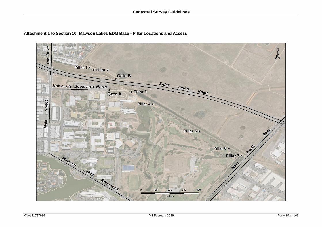
Cadastral Survey Guidelines
KNet 11757936 V3 February 2019 Page 89 of 163
Attachment 1 to Section 10: Mawson Lakes EDM Base - Pillar Locations and Access
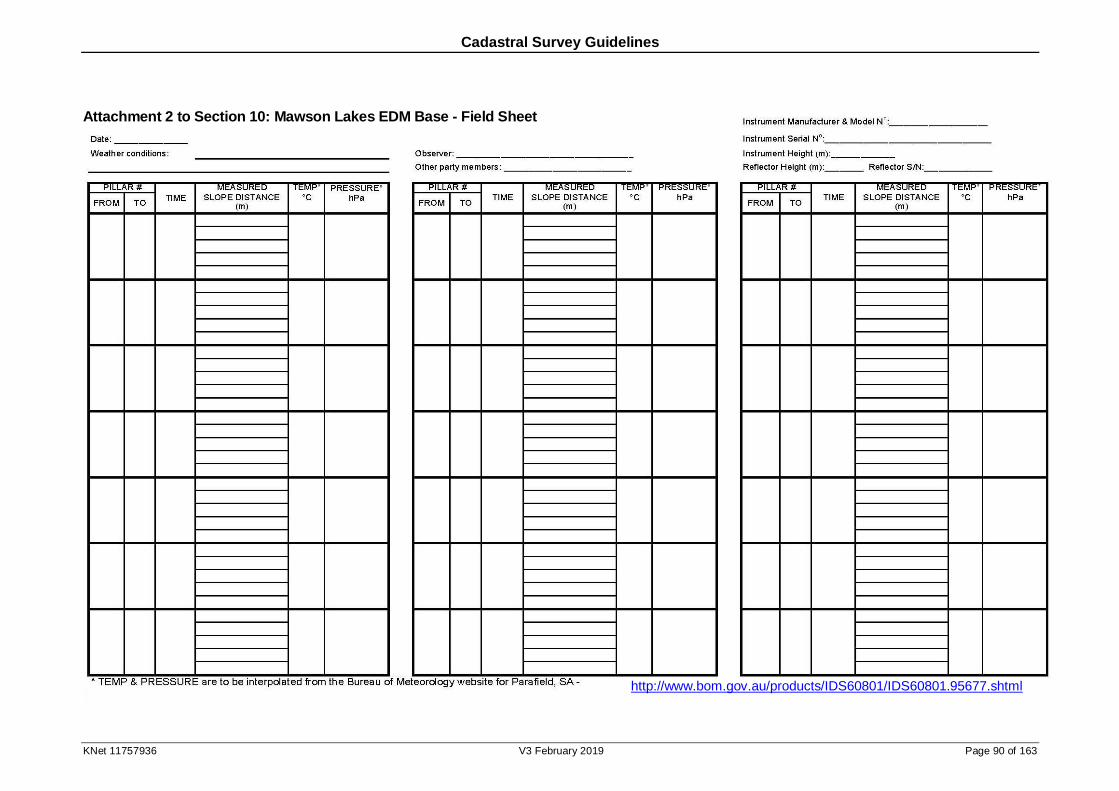
Cadastral Survey Guidelines
KNet 11757936 V3 February 2019 Page 90 of 163
Attachment 2 to Section 10: Mawson Lakes EDM Base - Field Sheet
http://www.bom.gov.au/products/IDS60801/IDS60801.95677.shtml
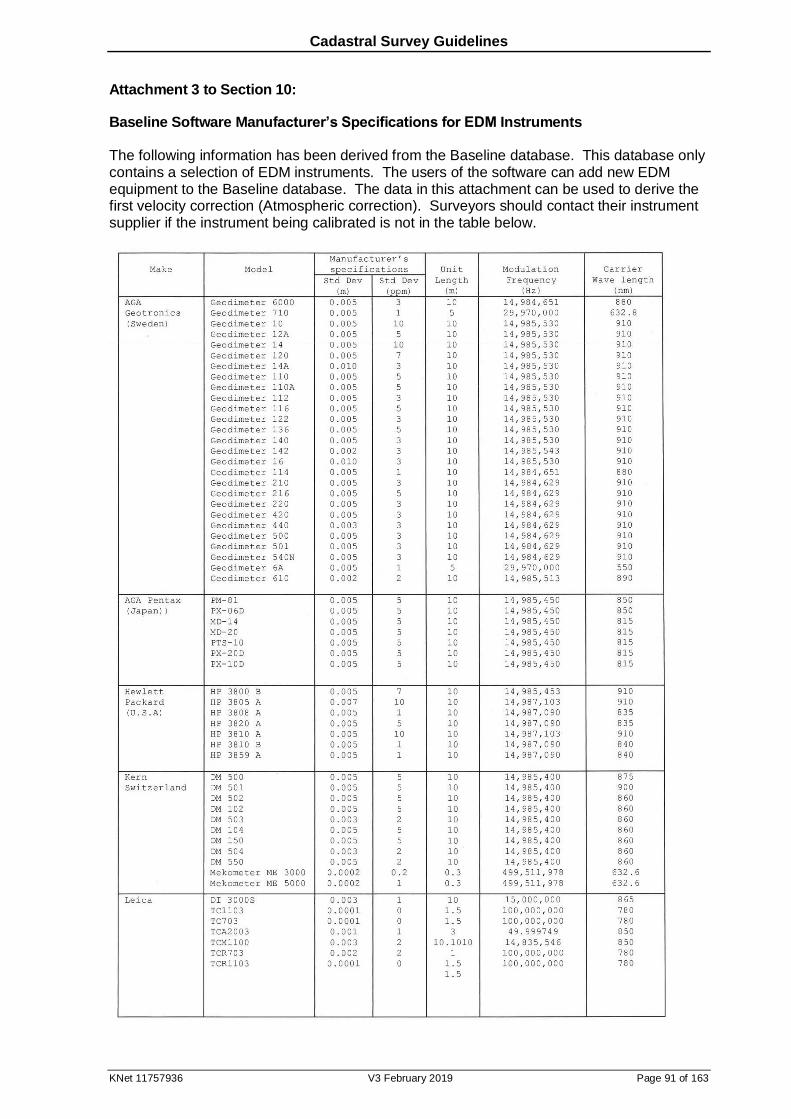
Cadastral Survey Guidelines
KNet 11757936 V3 February 2019 Page 91 of 163
Attachment 3 to Section 10:
Baseline Software Manufacturer’s Specifications for EDM Instruments
The following information has been derived from the Baseline database. This database only contains a selection of EDM instruments. The users of the software can add new EDM equipment to the Baseline database. The data in this attachment can be used to derive the first velocity correction (Atmospheric correction). Surveyors should contact their instrument supplier if the instrument being calibrated is not in the table below.

Cadastral Survey Guidelines
KNet 11757936 V3 February 2019 Page 92 of 163

Cadastral Survey Guidelines
KNet 11757936 V3 February 2019 Page 93 of 163
Cadastral Survey Guidelines
KNet 11757936 V3 February 2019 Page 94 of 163
11 Historical Survey Marking Practices
11.1 Introduction
Case law precedents have established the principle that the original survey marks set by the surveyor defined the boundaries and were paramount to all other boundary evidence. Accordingly surveyors should ensure that they are aware of the types and locations of marks that have been used on early surveys.
The appreciable number of survey marks on old surveys that were not noted on the survey plan or only referred to in the broadest of terms highlights the need for familiarity with early survey marking practices.
The Handbooks for Government Surveyors, regulations and occasional instructions from the Surveyor-General all set the guidelines for the particular era. Then, as now, compliance with marking requirements depended on the diligence and professionalism of the individual surveyor.
This Section has been prepared to:
augment surveyors' knowledge of early South Australian survey practices,
assist surveyors in searching, locating and identifying original marks, and
draw attention to practices where survey marks were noted solely on the field notes of Government surveyors and the consequent need to cover this area of search adequately.
The first attachment to this section reproduces some of the instructions and diagrams from the Survey Department of South Australia Handbook for Government Surveyors. This was the
fourth edition (1914) compiled by Mr C H Harris under the direction of the Surveyor-General.
The second of the attachments to this section summarises the marking practices used for Crown and Freehold surveys. The practices are outlined for five survey eras, as based on available procedures, handbooks and regulations.
11.2 Crown Surveys: Marking Practices
a. Earliest record of MP: 1895 (zinc alloy)
b. Earliest record of PM: 1923 (concrete filled bottle)
c. Metal Pins were placed in trenches at both 5 and 6 link offsets from pegs. (It is thought that the 6 link offset resulted from a misprint in instructions. See Extracts from Handbook for Government Surveyors Attachment page 77, clause 71, where 6 links is specified while Plate XV in the same attachment shows 5 links.) Offset distances of metal pins in trenches were not generally shown on the Diagram Book Pages (DBPs), however it is important to check carefully for notations on DBPs.
d. Metal Pins have been found on the production of boundaries (as well as the common practice of along the actual boundary lines).
e. Metal Pins, used up to the mid thirties, were of zinc alloy and crystallise in corrosive soils into a bluey green mass of approximately twice the original diameter.
f. Although referred to as Metal Pins on the DBPs, bottles and glass pins have been used in place of pins in the corrosive low-land soil of some irrigation areas; extra careful digging required.
g. The positions of old marks found or Metal Pins placed are frequently indicated on DBPs by blue or red circles respectively. It may be necessary to view original ‘pages’ if the circle type is not obvious from the monotone print.
h. Government Surveyor field books provide valuable and more detailed information on trenching, placement of metal pins etcetera than shown on the DBPs.
Cadastral Survey Guidelines
KNet 11757936 V3 February 2019 Page 95 of 163
i. Line pegs at the ends of trenches were not shown on the DBPs.
j. Pegs, trenches and metal pins were placed on the ‘run’ sides of roads and on the production of section boundary lines across roads, but these were not necessarily shown on the DBP.
k. Placement of boundary line pegs and trenches at intervals from 140 - 240 m (7-12 chains) was noted in field books but not on the DBPs.
l. Mile Posts, if cut from native timber, were placed in the ground with branch stems pointing down.
m. Iron pins replaced the zinc alloy pin in the 1940s; sometimes shown on the DBP as IS or IP until notation was standardised in the 1950s as MP.
n. Double Permanent Marks (DPMs) were used in the 1950s and 1960s as protection against possible damage of the surface PM.
o. Single PMs and MPs were sometimes placed deep (0.5m) for protection.
p. Bolts, droppers and other miscellaneous metal rods have been used as metal pins.
q. On rare occasions rockpiles in the shape of mini cairns rather than lines (trenches) have been found at old corners and datum pegs.
11.3 Crown Surveys: Surveying Practices
a. Consistency in measurement improved with the use of the steel band in the 1880s. The scale difference in comparisons with surveys of the 1880 - 1890 period of approximately one link in ten chains reflects a carry over of chaining practices used with the Gunters chain. The routine provided for the additional measurement of one link after each tenth measurement to allow for kinks or twigs caught in the chain.
b. Invar bands were first used in 1911. The 1970’s saw the transition from ‘chaining’ to EDM. In the early 1970’s there was little use of EDM on boundary surveys, however, by 1980 few surveys were measured without any EDM. GPS had been introduced on occasional rural cadastral surveys by 1990. By 2000 its use was quite common in rural and broadacre areas, with sporadic use on urban surveys.
c. Early practices adopted the actual fencing as the boundary; the offsets shown on the plan are from the pegged tie line to the fence boundary and not from a pegged survey boundary to the fence; see Extracts from Handbook for Government Surveyors paragraph 70 attached to this section.
The survey tie line was generally shown as a dashed line on the DBP but on occasions as a solid line; see enlargement C on Plate IX in Extracts from Handbook for Government Surveyors attached to this section.
On other occasions perusal of the field book will be necessary to confirm the fence was intended to be adopted for the boundary, and for detail of the offsets; see Figures 11.1 and 11.2. In this case the only clue that there may be more information relevant to the south western boundary of section 165 is the labelling of this boundary as ‘3 Wire Fence 2 rail’. There is no enlargement on this DBP. In this case perusal of the field book (as well as confirming the intention and providing offset details) is necessary to:
confirm that the angles on the DBP refer to a tie line and not the boundary, and
clarify what point the chainages on the DBP refer to (see the north western corner of section 165).
Note also in Figure 11.2 that the fenced boundary is shown dashed while the tie line is solid.
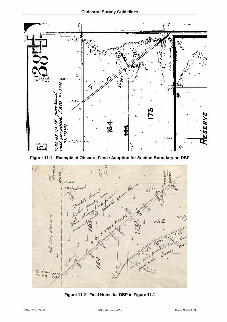
Cadastral Survey Guidelines
KNet 11757936 V3 February 2019 Page 96 of 163
Figure 11.1 - Example of Obscure Fence Adoption for Section Boundary on DBP
Figure 11.2 - Field Notes for DBP in Figure 11.1

Cadastral Survey Guidelines
KNet 11757936 V3 February 2019 Page 97 of 163
In many cases now the original fences have been replaced, however from other boundary evidence it may be possible to reconstruct the tieline (show on plan) and subsequently the fence position using the offsets.
Data shown in blue on DBPs for boundary angles and distances results from calculation of tieline and offset data for the issue of land grant. In some cases land grants have been issued erroneously with tieline angles and distances representing boundary data.
d. Dashed lines on a DBP indicate unsurveyed boundaries. An exception may be the dashed offside of a road, surveyed but not delineated as road at the date of lodgement. The field book may reveal that it had been surveyed as road.
e. Requirements for zero angle closures for all sections on DBPs after 1910 were sometimes achieved by an office adjustment, as reflected in differences between DBP and field book angle entries.
f. Data shown in blue on DBPs result from adjustment of data for the issue of land grant. This may not be obvious from monotone prints. Offside distances were usually calculated by office staff from observed ‘run’ distances. As these offside distances were often rounded and sometimes in error by a couple of links their value in relaying boundaries is subordinate to the observed ‘run’ chainages.
g. Chief Surveyor instructions in the 1950s required unclosed roads or section boundaries to be check chained and checked for alignment by astronomical observations. Notations (AM, PM or Mean) in reference to Sun Observations were to alert possible variance from True Bearing due to instrument or Latitude error.
11.4 Freehold Surveys: Marking Practices
a. Between 1836-1861 division of freehold land may or may not have been marked on the ground. The Real Property Act No. 15 of 1857 only required the proprietor to deposit a plan at the Registry Office signed and declared as to accuracy by the proprietor. Then the Real Property Act Amendment Act of 1861 required the plan to be certified as accurate by a licensed surveyor. There was no specified form of marking.
b. Various Acts relating to Local Government make the earliest reference to marking that affected freehold land:
1. Section 106 in Legislative Ordinance No.11 of 1849 for the City of Adelaide provided for the width of footways of streets to be set out and marked by posts. The width of the footways were measured from the curb-stone or exterior edge with plans prepared and signed by the Mayor.
2. Provision by Municipal Corporations for streets to be aligned dated from about 1861.
3. Section 115 of the Municipal Corporations Act of 1890 specified placement of permanent marks as aids in defining the alignments of streets and roads; placed on the corners and bends of parallel tie-lines. Note that some of these alignments were ‘unofficial’ (not gazetted) and the relationship between permanent mark and boundary was generally not recognised until the connection was determined on a later cadastral survey. It should also be noted that while ‘official’ alignments prevailed for road boundaries they aligned, again the relationship to side and rear boundaries requires connection to be determined on a later cadastral survey.
4. Section 18 of the Municipal Corporations Act Amendment Act 1914 extended the requirements for placement of permanent marks (of unspecified construction) to apply to any plan showing land divided into streets and allotments, either existing or proposed, and approved by the Surveyor-General.
5. At least two permanent marks (generally 1 inch galvanised iron pipes) were placed on all surveys of freehold urban land between January 1915 and August 1929 (DPs 2336 - 3832 inclusive).
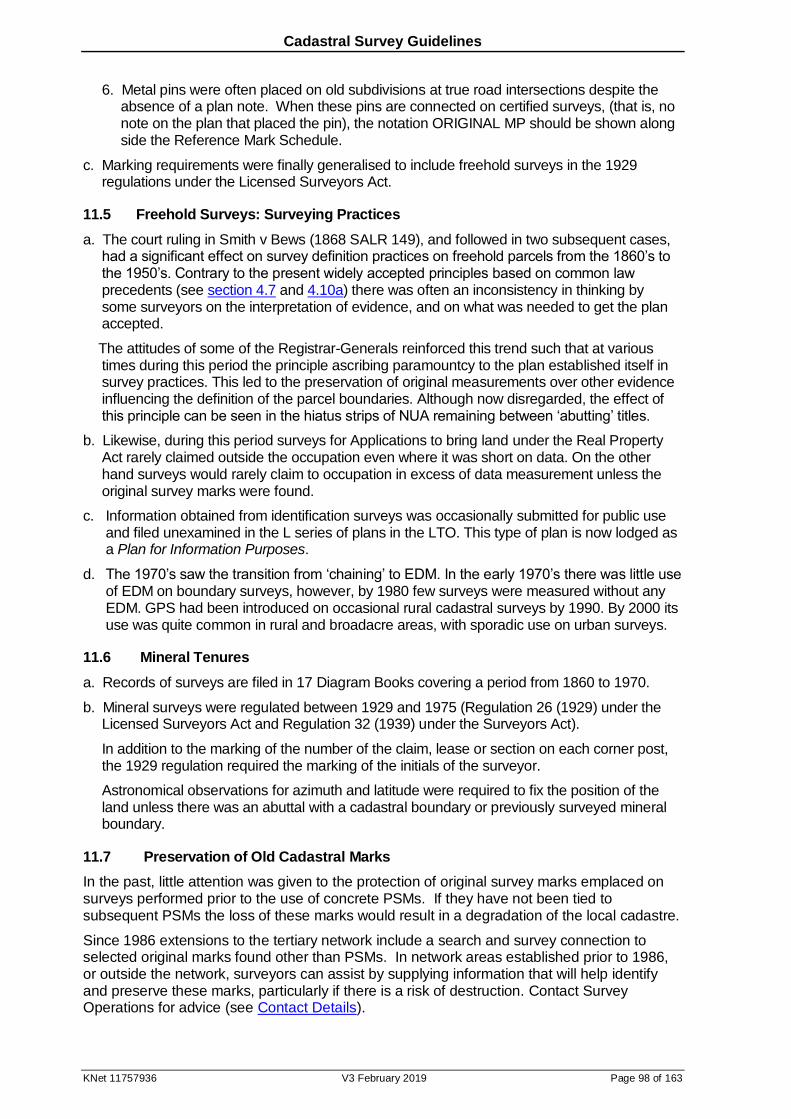
Cadastral Survey Guidelines
KNet 11757936 V3 February 2019 Page 98 of 163
6. Metal pins were often placed on old subdivisions at true road intersections despite the absence of a plan note. When these pins are connected on certified surveys, (that is, no note on the plan that placed the pin), the notation ORIGINAL MP should be shown along side the Reference Mark Schedule.
c. Marking requirements were finally generalised to include freehold surveys in the 1929 regulations under the Licensed Surveyors Act.
11.5 Freehold Surveys: Surveying Practices
a. The court ruling in Smith v Bews (1868 SALR 149), and followed in two subsequent cases, had a significant effect on survey definition practices on freehold parcels from the 1860’s to the 1950’s. Contrary to the present widely accepted principles based on common law precedents (see section 4.7 and 4.10a) there was often an inconsistency in thinking by some surveyors on the interpretation of evidence, and on what was needed to get the plan accepted.
The attitudes of some of the Registrar-Generals reinforced this trend such that at various times during this period the principle ascribing paramountcy to the plan established itself in survey practices. This led to the preservation of original measurements over other evidence influencing the definition of the parcel boundaries. Although now disregarded, the effect of this principle can be seen in the hiatus strips of NUA remaining between ‘abutting’ titles.
b. Likewise, during this period surveys for Applications to bring land under the Real Property Act rarely claimed outside the occupation even where it was short on data. On the other hand surveys would rarely claim to occupation in excess of data measurement unless the original survey marks were found.
c. Information obtained from identification surveys was occasionally submitted for public use and filed unexamined in the L series of plans in the LTO. This type of plan is now lodged as a Plan for Information Purposes.
d. The 1970’s saw the transition from ‘chaining’ to EDM. In the early 1970’s there was little use of EDM on boundary surveys, however, by 1980 few surveys were measured without any EDM. GPS had been introduced on occasional rural cadastral surveys by 1990. By 2000 its use was quite common in rural and broadacre areas, with sporadic use on urban surveys.
11.6 Mineral Tenures
a. Records of surveys are filed in 17 Diagram Books covering a period from 1860 to 1970.
b. Mineral surveys were regulated between 1929 and 1975 (Regulation 26 (1929) under the Licensed Surveyors Act and Regulation 32 (1939) under the Surveyors Act).
In addition to the marking of the number of the claim, lease or section on each corner post, the 1929 regulation required the marking of the initials of the surveyor.
Astronomical observations for azimuth and latitude were required to fix the position of the land unless there was an abuttal with a cadastral boundary or previously surveyed mineral boundary.
11.7 Preservation of Old Cadastral Marks
In the past, little attention was given to the protection of original survey marks emplaced on surveys performed prior to the use of concrete PSMs. If they have not been tied to subsequent PSMs the loss of these marks would result in a degradation of the local cadastre.
Since 1986 extensions to the tertiary network include a search and survey connection to selected original marks found other than PSMs. In network areas established prior to 1986, or outside the network, surveyors can assist by supplying information that will help identify and preserve these marks, particularly if there is a risk of destruction. Contact Survey Operations for advice (see Contact Details).

Cadastral Survey Guidelines
KNet 11757936 V3 February 2019 Page 99 of 163
The 2.5cm diameter GIP (PM) in use on freehold land divisions from 1915 to 1929, as recorded on DPs 2336 to 3832 inclusive, are probably of immediate concern but existing corner pegs of this era or from early freehold surveys are also included.
The triangular corner pegs, flat road bend pegs and white metal pins or glass pins emplaced on Crown surveys prior to 1923, or later surveys when PSMs were sparingly used, are also of concern.
If any of these original marks are found in the course of certified surveys the recommended options are:
tie to survey and show on plan,
convert to a PSM, or
preserve the mark where applicable with a dropper.
If found on identification or engineering surveys:
notify Survey Operations of the mark location by email to [email protected], and
preserve the mark where applicable with a dropper.
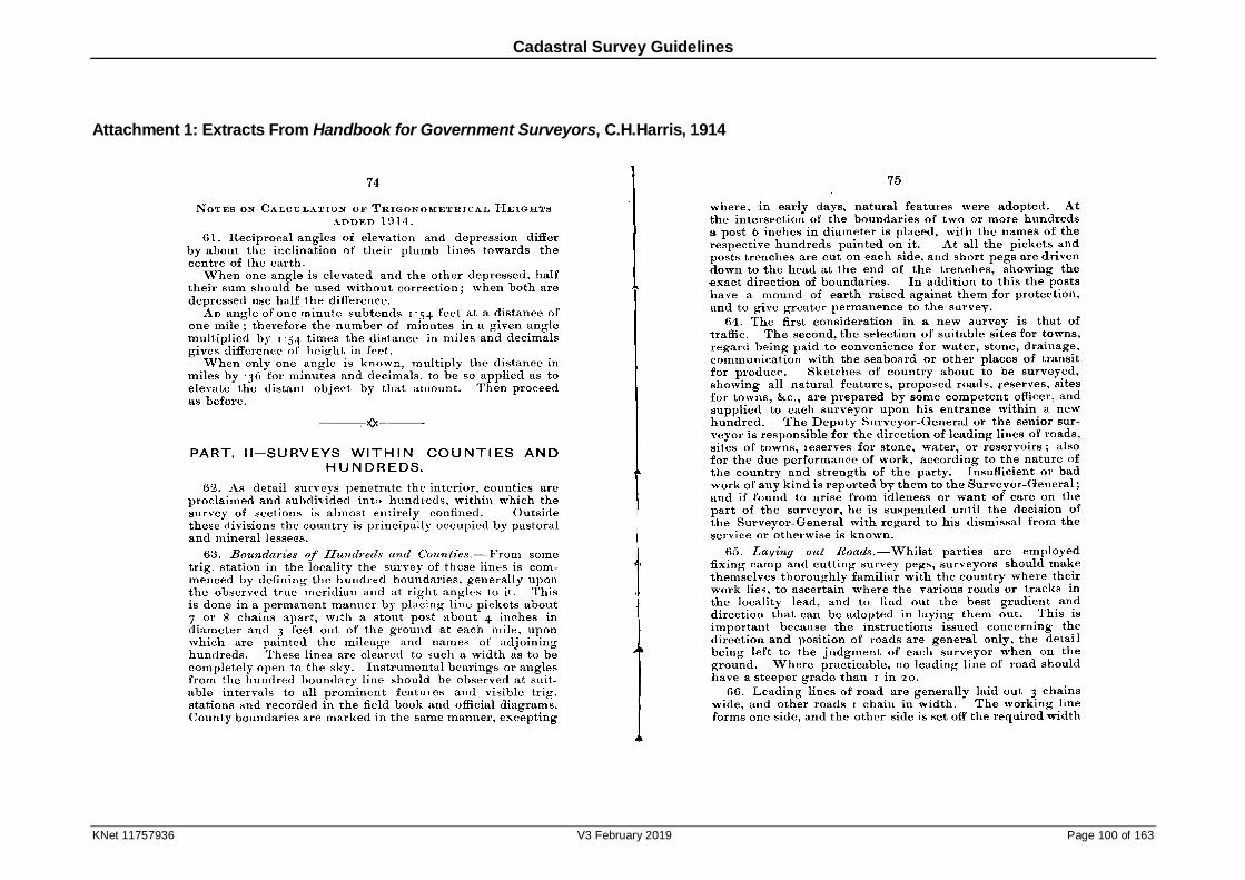
Cadastral Survey Guidelines
KNet 11757936 V3 February 2019 Page 100 of 163
Attachment 1: Extracts From Handbook for Government Surveyors, C.H.Harris, 1914
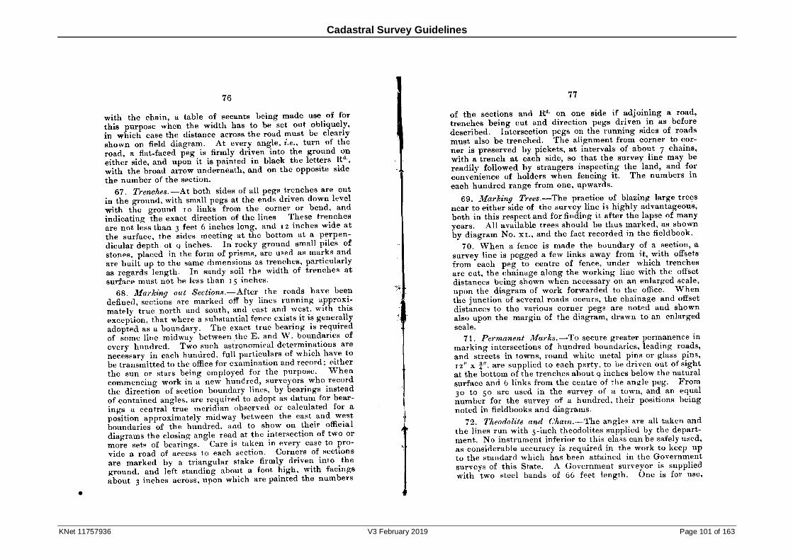
Cadastral Survey Guidelines
KNet 11757936 V3 February 2019 Page 101 of 163
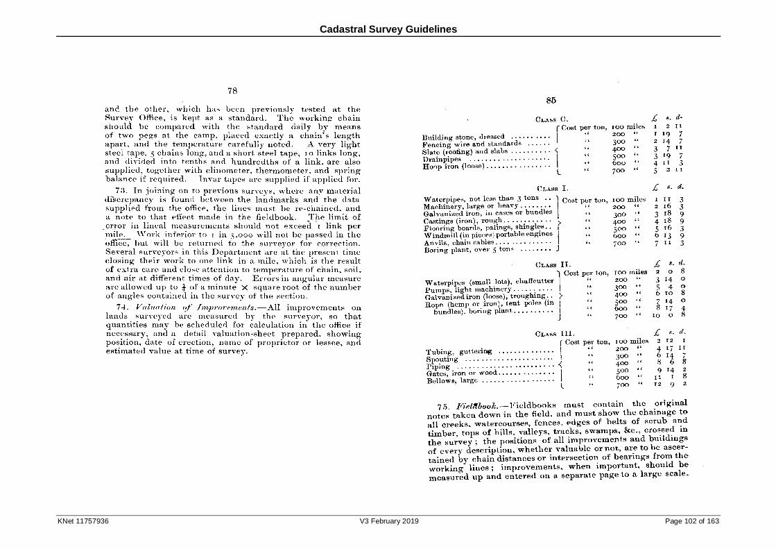
Cadastral Survey Guidelines
KNet 11757936 V3 February 2019 Page 102 of 163
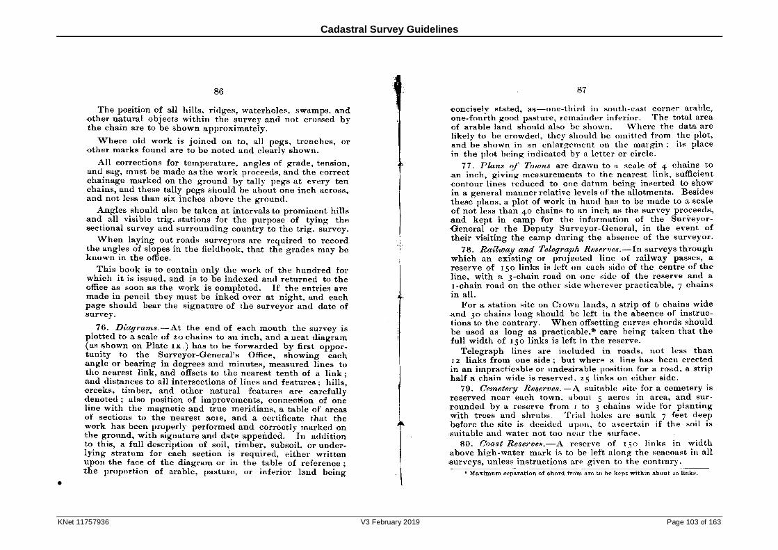
Cadastral Survey Guidelines
KNet 11757936 V3 February 2019 Page 103 of 163
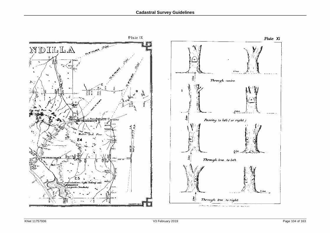
Cadastral Survey Guidelines
KNet 11757936 V3 February 2019 Page 104 of 163
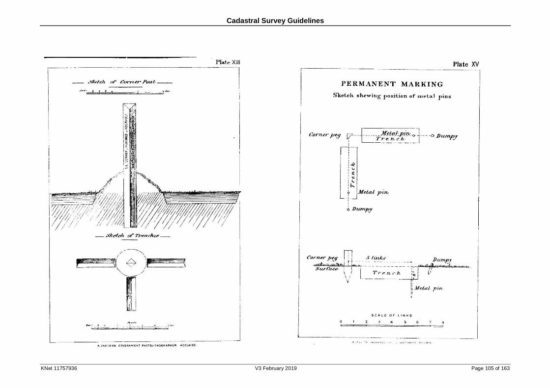
Cadastral Survey Guidelines
KNet 11757936 V3 February 2019 Page 105 of 163
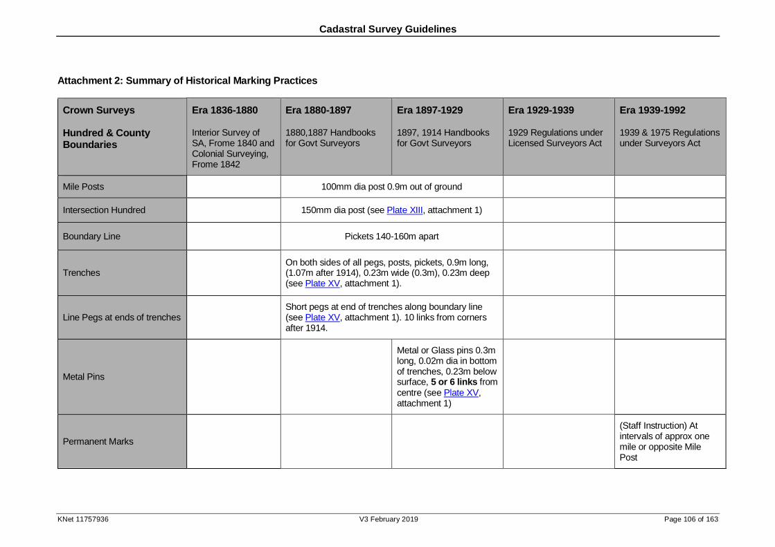
Cadastral Survey Guidelines
KNet 11757936 V3 February 2019 Page 106 of 163
Attachment 2: Summary of Historical Marking Practices
Crown Surveys
Hundred & County Boundaries
Era 1836-1880
Interior Survey of SA, Frome 1840 and Colonial Surveying, Frome 1842
Era 1880-1897
1880,1887 Handbooks for Govt Surveyors
Era 1897-1929
1897, 1914 Handbooks for Govt Surveyors
Era 1929-1939
1929 Regulations under Licensed Surveyors Act
Era 1939-1992
1939 & 1975 Regulations under Surveyors Act
Mile Posts 100mm dia post 0.9m out of ground
Intersection Hundred 150mm dia post (see Plate XIII, attachment 1)
Boundary Line Pickets 140-160m apart
Trenches On both sides of all pegs, posts, pickets, 0.9m long, (1.07m after 1914), 0.23m wide (0.3m), 0.23m deep (see Plate XV, attachment 1).
Line Pegs at ends of trenches Short pegs at end of trenches along boundary line (see Plate XV, attachment 1). 10 links from corners after 1914.
Metal Pins
Metal or Glass pins 0.3m long, 0.02m dia in bottom of trenches, 0.23m below surface, 5 or 6 links from centre (see Plate XV, attachment 1)
Permanent Marks
(Staff Instruction) At intervals of approx one mile or opposite Mile Post
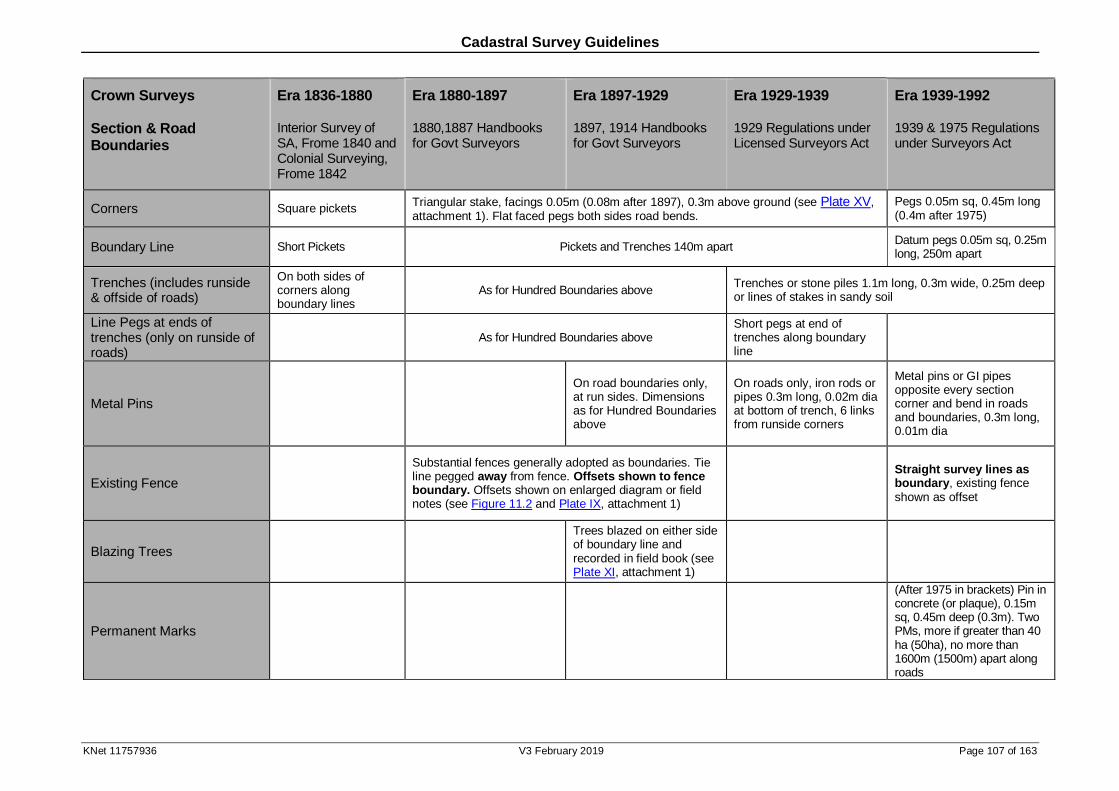
Cadastral Survey Guidelines
KNet 11757936 V3 February 2019 Page 107 of 163
Crown Surveys
Section & Road Boundaries
Era 1836-1880
Interior Survey of SA, Frome 1840 and Colonial Surveying, Frome 1842
Era 1880-1897
1880,1887 Handbooks for Govt Surveyors
Era 1897-1929
1897, 1914 Handbooks for Govt Surveyors
Era 1929-1939
1929 Regulations under Licensed Surveyors Act
Era 1939-1992
1939 & 1975 Regulations under Surveyors Act
Corners Square pickets Triangular stake, facings 0.05m (0.08m after 1897), 0.3m above ground (see Plate XV, attachment 1). Flat faced pegs both sides road bends.
Pegs 0.05m sq, 0.45m long (0.4m after 1975)
Boundary Line Short Pickets Pickets and Trenches 140m apart Datum pegs 0.05m sq, 0.25m long, 250m apart
Trenches (includes runside & offside of roads)
On both sides of corners along boundary lines
As for Hundred Boundaries above Trenches or stone piles 1.1m long, 0.3m wide, 0.25m deep or lines of stakes in sandy soil
Line Pegs at ends of trenches (only on runside of roads)
As for Hundred Boundaries above Short pegs at end of trenches along boundary line
Metal Pins
On road boundaries only, at run sides. Dimensions as for Hundred Boundaries above
On roads only, iron rods or pipes 0.3m long, 0.02m dia at bottom of trench, 6 links from runside corners
Metal pins or GI pipes opposite every section corner and bend in roads and boundaries, 0.3m long, 0.01m dia
Existing Fence
Substantial fences generally adopted as boundaries. Tie line pegged away from fence. Offsets shown to fence boundary. Offsets shown on enlarged diagram or field notes (see Figure 11.2 and Plate IX, attachment 1)
Straight survey lines as boundary, existing fence shown as offset
Blazing Trees
Trees blazed on either side of boundary line and recorded in field book (see Plate XI, attachment 1)
Permanent Marks
(After 1975 in brackets) Pin in concrete (or plaque), 0.15m sq, 0.45m deep (0.3m). Two PMs, more if greater than 40 ha (50ha), no more than 1600m (1500m) apart along roads
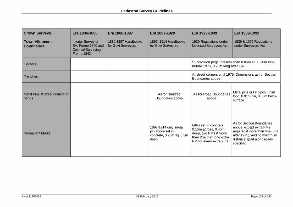
Cadastral Survey Guidelines
KNet 11757936 V3 February 2019 Page 108 of 163
Crown Surveys
Town Allotment Boundaries
Era 1836-1880
Interior Survey of SA, Frome 1840 and Colonial Surveying, Frome 1842
Era 1880-1897
1880,1887 Handbooks for Govt Surveyors
Era 1897-1929
1897, 1914 Handbooks for Govt Surveyors
Era 1929-1939
1929 Regulations under Licensed Surveyors Act
Era 1939-1992
1939 & 1975 Regulations under Surveyors Act
Corners Subdivision pegs, not less than 0.05m sq, 0.38m long before 1975, 0.25m long after 1975
Trenches At street corners until 1975. Dimensions as for Section Boundaries above
Metal Pins at street corners or bends
As for Hundred
Boundaries above As for Road Boundaries
above
Metal pins or GI pipes, 0.3m long, 0.01m dia, 0.05m below surface
Permanent Marks
1897-1914 only, metal pin above set in concrete, 0.23m sq, 0.3m deep
GIPs set in concrete 0.15m across, 0.45m deep, two PMs if more than 2ha then one extra PM for every extra 2 ha
As for Section Boundaries above, except extra PMs required if more than 4ha (5ha after 1975), and no maximum distance apart along roads specified

Cadastral Survey Guidelines
KNet 11757936 V3 February 2019 Page 109 of 163
Crown Surveys
Pastoral Boundaries (Runs)
Era 1836-1880
Interior Survey of SA, Frome 1840 and Colonial Surveying, Frome 1842
Era 1880-1897
1880,1887 Handbooks for Govt Surveyors
Era 1897-1929
1897, 1914 Handbooks for Govt Surveyors
Era 1929-1939
1929 Regulations under Licensed Surveyors Act
Era 1939-1992
1939 & 1975 Regulations under Surveyors Act
(1888 Instructions to Surveyors under the Licensed Surveyors Act, 1886)
Corners Poles 1.8m high, 0.1m dia with pile of stones or earth at foot (1888-1975)
Boundary Lines Intermediate pickets and trenches on prominent points (1888-1975)
Trenches Trenches or piles of stones along boundary directions (1888-1975)
Freehold Surveys
Era 1836-1880
Era 1880-1897
Era 1897-1929
Era 1929-1939
1929 Regulations under Licensed Surveyors Act
Era 1939-1992
1939 & 1975 Regulations under Surveyors Act
(Municipal Corp Act 1890) (Municipal Corp Act 1914)
Corners As for Crown Surveys
Boundary Lines As for Crown Surveys
Metal Pins As for Crown Surveys
Permanent Marks PMs on corners of street alignment tie lines
At least two ‘PMs’ on each DP (usually 0.16m dia GI Pipes)
As for Crown Surveys
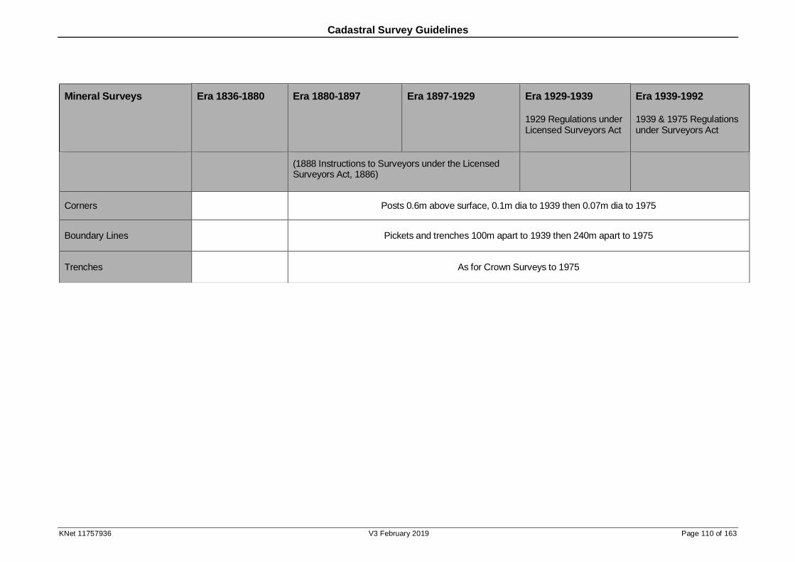
Cadastral Survey Guidelines
KNet 11757936 V3 February 2019 Page 110 of 163
Mineral Surveys
Era 1836-1880
Era 1880-1897
Era 1897-1929
Era 1929-1939
1929 Regulations under Licensed Surveyors Act
Era 1939-1992
1939 & 1975 Regulations under Surveyors Act
(1888 Instructions to Surveyors under the Licensed Surveyors Act, 1886)
Corners Posts 0.6m above surface, 0.1m dia to 1939 then 0.07m dia to 1975
Boundary Lines Pickets and trenches 100m apart to 1939 then 240m apart to 1975
Trenches As for Crown Surveys to 1975
Cadastral Survey Guidelines
KNet 11757936 V3 February 2019 Page 111 of 163
12 Natural Boundaries
12.1 Introduction
Boundaries present themselves in one of two forms, either as natural or artificial boundaries. Natural boundaries are ambulatory in nature and the doctrine of accretion asserts that they may move in position providing that change is imperceptible in time.
Natural boundaries are those evidenced by naturally occurring phenomena such as the seacoast, inland waters and mountain ranges. The most common natural boundaries dealt with by surveyors in South Australia are those defined by the mean high water mark (MHWM), or the centre line or banks of streams. Surveyors also deal with boundaries created parallel to natural boundaries (150 link reserves); such boundaries are generally not ambulatory.
Water boundaries are classified as being either riparian (streams) or littoral (shores, that is lakes or the sea and its inlets). It should be noted that the term riparian is commonly used to include littoral boundaries; unless otherwise specified this section shall do the same.
In South Australia disputes over riparian rights are rare as there is a relatively small proportion of land parcels with natural boundaries, due to the lack of substantial watercourses and fresh water lakes.
See PPG sections 12 and 19 for natural boundary plan requirements.
12.2 Controlling Legislation
This section refers to some legislation relevant to the ownership of the seabed and the bed of the River Murray. As there is no specific legislation relating to the surveying of natural boundaries the following common law rulings and discussion has been presented to assist understanding.
12.3 Tidal Boundary Definitions and Principles
a. Mean High Water Mark
A-G v Chambers is the precedent generally adopted for the extent of parcels bounded by tidal
waters. This case was to resolve the question of the landward extent of the Crown’s right to the seashore. While this judgement confirmed the extent as MHWM (also known as medium high water mark or ordinary high water mark, OHWM) it was somewhat imprecise in defining MHWM. The judgement refers to:
This point of the shore therefore is about four days in every week, i.e., for the most part of the year, reached and covered by the tides.27
...the average of these medium tides in each quarter of a lunar revolution during the year...
...the line of the medium high tide between the springs and the neaps. All land below that line is more often than not covered at high water, and so may justly be said, in the language of Lord Hale, to be covered by the ordinary flux of the sea. This cannot be said of any land above that line...
Comment on this case has come from the Crown Solicitor (DL 3533/1967):
27 May not be applicable to areas such as South Australia that have mixed tides, that is, two high tides per day having
marked inequalities in height. A tidal datum based on the higher of these two daily high waters is referred to as mean higher high water.
Cadastral Survey Guidelines
KNet 11757936 V3 February 2019 Page 112 of 163
... misunderstanding has subsequently arisen from the Lord Chancellor’s reference to “the medium high tide between the springs and the neaps”. The words underlined are descriptive only and are not, in my view, juristically definitive: they could, without changing the meaning of the passage in which they occur, have been omitted. The highwater mark of the ordinary tides, not the average of spring and neap tides, fixes the boundary.
Hallmann (1994, para. 13.40) concludes:
Where lands are bounded by tidal waters, the common law rule is that the boundary is the mean high-water mark, ie. the mean of all high tides including the spring and neap tides taken over a sufficiently long period...
Logically, if the extent of the Crown’s right to the seashore is MHWM then any land alienated from the Crown abutting the seashore, unless otherwise described, extends to MHWM. ‘Low water mark’ is a description of a boundary where it is clearly intended that parcels extend over part of the seashore.
It is quite common to find that the line located for the coast on early surveys of waterfront parcels was some distance inland from MHWM. In many cases this is not attributable to the ambulatory nature of the MHWM. The position located by these surveyors was often a line (sometimes labelled) of edge of vegetation, accumulation of debris, cliff edge or top of bank. Redefinition of the seaward boundary of a coastal parcel inland from MHWM would probably require evidence of intention by the Crown to retain a strip of land between that parcel and MHWM.
b. Tidal Rivers Halsbury’s (1998, para.355-14015) comments:
Where land is described as abutting a tidal …river, it is presumed, as with the seashore, that the mean high water mark constitutes the boundary. The common law distinguishes between tidal …rivers and non-tidal…rivers. Where the river is a tidal…the land forming the bed and channel through which the river runs, the alveus28, belongs to the Crown up to the mean high water mark.
In the absence of any specific legislative definition, ‘tidal waters’ means those in which the tide ebbs and flows under the gravitational influence of the sun and the moon.
Hallmann (para. 4.4) clarifies that:
The tides must be in evidence for more than half of each and every year. Waters that do not answer that description, or waters that are only intermittently tidal so at times to be naturally cut off from the sea, are deemed at law to be non-tidal waters...
Anecdotal evidence suggests that prior to the construction of the Murray mouth barrages, salt water at times reached as far up the river as Mannum. Furthermore, it is thought that the river may have been influenced by the ebb and flow of tides as far upstream as Blanchetown.
c. Control of the Sea Bed
Raven v Keane confirms the extent, and status, of the foreshore: ‘The foreshore, that part of the seashore between ordinary high-water mark and low-water mark, prima facie belongs to the Crown.’
Under Section 15 of the Harbors and Navigation Act 1993 adjacent land is vested in fee simple in the Minister. Section 4 includes in the definition of adjacent land:
28 ‘Alveus’ is defined as ‘the land forming the bed and channel through which a stream ordinarily flows’.
Cadastral Survey Guidelines
KNet 11757936 V3 February 2019 Page 113 of 163
land extending from the low water mark on the seashore to the nearest road or section boundary, or to a distance of 50 metres from high water mark (whichever is the lesser distance)...
Section 18 (4) provides that this land: ‘...if within the area of a council but not within a harbor - under the care, control and management of the council...’
Land vested in the Minister under Section 15 also includes land underlying the territorial sea adjacent to the State. Under the Seas and Submerged Lands Act 1973 the territorial sea extends seaward for three nautical miles from low water mark, agreed baselines, or from bay closing lines joining the headlands at the mouth of true bays.
In relation to Council boundaries the Crown Solicitor (HB 1059/25) advised that:
...the proper interpretation to be placed upon the words “coast”, “seacoast”, or “seashore” where they, or any of them, are used, without being defined, to fix the seaward boundary ... of a Municipality or a District Council District, is that the boundary extends to low water mark... [italics added].
In recent times the boundaries of some National Parks have been extended to lowest astronomical tide. Lowest astronomical tide is defined as the lowest height of the surface of the sea which can be predicted to occur under average meteorological conditions and under any combination of astronomical conditions.
12.4 Methods for Determining MHWM
An obvious point is expressed by the Manual of the NSW Integrated Survey Grid (1976, para
22.4): ‘The determination of the limit of mean high water presents no difficulty when the foreshore is steep. On flat grades and where mangrove swamps exist, great care is necessary.’
Where it is necessary to locate on site the present position of MHWM the following methods should be considered. It is recommended that surveyors utilise the current year’s SA Government Tide Tables. These tables provide instructions for tidal predictions. Where additional tidal information is required beyond that in the Tide Tables:
consult Australian National Tide Tables (ANTT) on the Bureau of Meteorology website, or
seek advice from Flinders Ports Pty Ltd.
The main methods utilise a value which is the average of all the high tides for the local area. This value can be observed at the appropriate time or set out using the relationship between the tide gauge and height control. The two main methods shall be referred to as:
observing the water’s edge, and
setting out the MHWM contour.
The advantage of observing the water’s edge is that at appropriate times the MHWM is self-evident. A problem with this method is that it is only suitable in calm conditions; at locations where swell waves are less than 0.5m at breaking29. The method is often capable of use in South Australia because much of the coast in settled areas is protected from swells of this magnitude.
Setting out the MHWM contour overcomes uncertainty involved with breaking waves. However, this method is only practical for those parts of the coast within levelling distance of AHD control
29 Even after averaging out the water level fluctuations, breaking waves induce a higher still water level inside the breaker zone. This higher still water level will vary with the slope and nature of the coast, but is generally about a tenth of the offshore
wave height. On exposed coasts the tide heights at the beach will nearly always be between 0.1m to 0.6m higher than those deduced from nearby tide gauges depending on the prevailing wave height.
Cadastral Survey Guidelines
KNet 11757936 V3 February 2019 Page 114 of 163
or a tide gauge. An additional problem with levelling from AHD control is that the uncertainty of the relationship between the local MHWM and the AHD increases the further one is from a tide gauge.
Due to the problems inherent in these methods it is recommended that wherever possible, a sample point located by one method be checked by the other.
a. Observing the Water’s Edge
Table 12.1 - MHWM at Standard Ports30
Standard Port MHWM above Chart Datum
AHD above Chart Datum
MHWM above AHD
Cape Jervis 1.10 0.87 0.23
Port Adelaide 2.01 1.45 0.56
Port Giles 1.79 1.54 0.25
Port Lincoln 1.23 0.83 0.40
Port Pirie 2.41 1.93 0.48
Thevenard 1.51 0.99 0.52
Victor Harbor 0.87 0.58 0.29
Wallaroo 1.34 1.14 0.20
Whyalla 2.18 1.70 0.48
Note that values in this table must be used in accordance with the qualifications expressed in this section. Chart datums for Ports may change in subsequent years; check the current year’s Tide Tables for an indication of such changes. The value for MHWM above AHD will not be affected by changes to chart datum.
1. from Tide Tables determine the Standard or Secondary Port adjacent to the area of interest.
If not adjacent to a Port some interpolation of predictions at Ports either side will be required.
2. if Secondary Ports are used in step 1, determine the Standard Port31 it is related to.
30 In Table 12.1 MHWM above chart datum has been determined by Land Boundaries Section from Tide Tables. This was
done by averaging all the predicted high waters for the months of March, June, September and December. Cape Jervis’s value was determined from 2008 predictions (when chart datum lowered 0.30m). Wallaroo’s value was determined from 2005 predictions (chart datum lowered 0.10m). Port Lincoln values were determined from 2004 predictions (chart datum raised 0.20m), Port Adelaide's (Outer Harbor) value was determined from 2001 predictions (chart datum raised 0.27m), Victor Harbor’s from 1999, Port Giles’s from 1998, and the remainder from 1997.
31 See ANTT for additional Secondary Ports. Those possibly useful include Arno Bay, Port Neill and Port Stanvac.
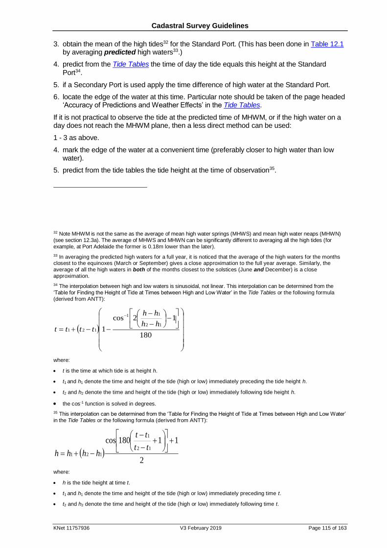
Cadastral Survey Guidelines
KNet 11757936 V3 February 2019 Page 115 of 163
3. obtain the mean of the high tides32 for the Standard Port. (This has been done in Table 12.1 by averaging predicted high waters33.)
4. predict from the Tide Tables the time of day the tide equals this height at the Standard
Port34.
5. if a Secondary Port is used apply the time difference of high water at the Standard Port.
6. locate the edge of the water at this time. Particular note should be taken of the page headed ‘Accuracy of Predictions and Weather Effects’ in the Tide Tables.
If it is not practical to observe the tide at the predicted time of MHWM, or if the high water on a day does not reach the MHWM plane, then a less direct method can be used:
1 - 3 as above.
4. mark the edge of the water at a convenient time (preferably closer to high water than low water).
5. predict from the tide tables the tide height at the time of observation35.
32 Note MHWM is not the same as the average of mean high water springs (MHWS) and mean high water neaps (MHWN) (see section 12.3a). The average of MHWS and MHWN can be significantly different to averaging all the high tides (for example, at Port Adelaide the former is 0.18m lower than the later).
33 In averaging the predicted high waters for a full year, it is noticed that the average of the high waters for the months closest to the equinoxes (March or September) gives a close approximation to the full year average. Similarly, the average of all the high waters in both of the months closest to the solstices (June and December) is a close approximation.
34 The interpolation between high and low waters is sinusoidal, not linear. This interpolation can be determined from the
‘Table for Finding the Height of Tide at Times between High and Low Water’ in the Tide Tables or the following formula (derived from ANTT):
180
12cos
112
11
121
hh
hh
tttt
where:
t is the time at which tide is at height h.
t1 and h1 denote the time and height of the tide (high or low) immediately preceding the tide height h.
t2 and h2 denote the time and height of the tide (high or low) immediately following tide height h.
the cos-1 function is solved in degrees.
35 This interpolation can be determined from the ‘Table for Finding the Height of Tide at Times between High and Low Water’ in the Tide Tables or the following formula (derived from ANTT):
2
11180cos12
1
121
tt
tt
hhhh
where:
h is the tide height at time t.
t1 and h1 denote the time and height of the tide (high or low) immediately preceding time t.
t2 and h2 denote the time and height of the tide (high or low) immediately following time t.
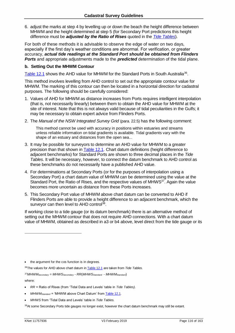
Cadastral Survey Guidelines
KNet 11757936 V3 February 2019 Page 116 of 163
6. adjust the marks at step 4 by levelling up or down the beach the height difference between MHWM and the height determined at step 5 (for Secondary Port predictions this height difference must be adjusted by the Ratio of Rises quoted in the Tide Tables).
For both of these methods it is advisable to observe the edge of water on two days, especially if the first day’s weather conditions are abnormal. For verification, or greater accuracy, actual tide readings at the Standard Port should be obtained from Flinders Ports and appropriate adjustments made to the predicted determination of the tidal plane.
b. Setting Out the MHWM Contour
Table 12.1 shows the AHD value for MHWM for the Standard Ports in South Australia36.
This method involves levelling from AHD control to set out the appropriate contour value for MHWM. The marking of this contour can then be located in a horizontal direction for cadastral purposes. The following should be carefully considered:
1. Values of AHD for MHWM as distance increases from Ports requires intelligent interpolation (that is, not necessarily linearly) between them to obtain the AHD value for MHWM at the site of interest. Note that this is not always valid because of tidal peculiarities in the Gulfs; it may be necessary to obtain expert advice from Flinders Ports.
2. The Manual of the NSW Integrated Survey Grid (para. 22.5) has the following comment:
This method cannot be used with accuracy in positions within estuaries and streams unless reliable information on tidal gradients is available. Tidal gradients vary with the shape of an estuary and distances from the open sea...
3. It may be possible for surveyors to determine an AHD value for MHWM to a greater precision than that shown in Table 12.1. Chart datum definitions (height difference to adjacent benchmarks) for Standard Ports are shown to three decimal places in the Tide Tables. It will be necessary, however, to connect the datum benchmark to AHD control as these benchmarks do not necessarily have a published AHD value.
4. For determinations at Secondary Ports (or for the purposes of interpolation using a Secondary Port) a chart datum value of MHWM can be determined using the value at the Standard Port, the Ratio of Rises, and the respective values of MHWS37. Again the value becomes more uncertain as distance from these Ports increases.
5. This Secondary Port value of MHWM above chart datum can be converted to AHD if Flinders Ports are able to provide a height difference to an adjacent benchmark, which the surveyor can then level to AHD control38.
If working close to a tide gauge (or its datum benchmark) there is an alternative method of setting out the MHWM contour that does not require AHD connections. With a chart datum value of MHWM, obtained as described in a3 or b4 above, level direct from the tide gauge or its
the argument for the cos function is in degrees.
36The values for AHD above chart datum in Table 12.1 are taken from Tide Tables.
37MHWMSecondary = MHWSSecondary - RR(MHWSStandard - MHWMStandard)
where:
RR = Ratio of Rises (from ‘Tidal Data and Levels’ table in Tide Tables).
MHWMStandard = ‘MHWM above Chart Datum’ from Table 12.1.
MHWS from ‘Tidal Data and Levels’ table in Tide Tables.
38At some Secondary Ports tide gauges no longer exist, however the chart datum benchmark may still be extant.
Cadastral Survey Guidelines
KNet 11757936 V3 February 2019 Page 117 of 163
datum benchmark. Levelling from the datum benchmark requires the height difference to chart datum (see Tide Tables for Standard Ports or Flinders Ports for Secondary Ports).
c. Other Methods
The methods described above are generally adequate for all cadastral surveys. On rare occasions a more accurate determination of the MHWM plane may be required at a site than is obtainable by these methods. This can be achieved by establishing a temporary tide gauge adjacent to the area of interest and recording and averaging all high water values over an appropriate period.
Surveyors experienced in determining MHWM by methods a and b above have noticed that a second seaweed line can sometimes be taken as a useful approximation for MHWM for medium to low energy beaches (that is where storm waves seldom exceed 1m). This method of determining MHWM may be suitable as an alternative to graphical methods.
This seaweed line method is to be avoided if at all possible by surveyors not experienced in determining MHWM by the more objective methods. While it has been known to sometimes give good results, it assumes an arbitrary balance between the stage of the tide, the slope of the beach and the amount of wave set-up and run-up. These vary greatly and the method has no logical support. Because wave run-up can be quite large (commonly over a metre in height), this method can lead to large errors if applied on open coasts.
12.5 Heights of Coastal Land
It is anticipated that there will be an increased requirement for surveys to determine contours for land to be subdivided and to establish heights for coastal development. Developers of coastal land are frequently required by local councils and the Development Assessment Commission to provide this information; this is likely to increase as more development is assessed for safety against extreme tides and the effects of sea level rise.
Where benchmarks are not conveniently located, sea level or seaweed marks have commonly been used as survey datum. However this does not always provide sufficient accuracy; the datum used needs to be sufficiently accurate to enable the development to be assessed. It would be desirable for surveyors to indicate the likely range of error when they use these approximate methods, though this has not been common practice in the past.
Where heights are likely to be critical, the accuracy needs to be at least within 0.1m. This is normally only achievable by levelling from AHD benchmarks.
To avoid the cost of levelling to a distant AHD benchmark this standard may be relaxed where land is well above the likely effects of extreme tides allowing for sea level rise (1.5m or more above the extreme wave swash level, which may be discernible from seaweed or other flotsam, or from local knowledge).
An approximate AHD value for the site may be derived by either of the two following methods. These approximate methods should only be used where the subject land or proposed development is sufficiently elevated to cover the estimated error in the method. Height accuracy from these methods to within 0.3m would be expected, and survey should only be carried out when this is attainable.
a. Height Transfer from the Nearest Tide Gauge
This method is only suitable in calm conditions, at locations where the swell waves are less than 0.5m at breaking, and if the site is within 50km of a tide gauge:
1. establish the height of a new benchmark, at the site, in relation to the sea water level and note the time of day.
2. make the appropriate adjustment for tidal travel (refer to Tide Tables) to the site and obtain
from Flinders Ports the actual recorded tide at the adjusted time.

Cadastral Survey Guidelines
KNet 11757936 V3 February 2019 Page 118 of 163
3. level from the tide gauge or its datum benchmark39 to AHD control.
4. deduce the height of the new benchmark at the site.
5. estimate the accuracy limits, taking into account the distance from the gauge, wind and sea conditions and any other factors, and indicate this on the survey drawing, together with notes on the method used.
b. Simultaneous Levelling
If there are no nearby tide gauges, but there is AHD control within 20km of the site of interest, the following method may suffice in some instances. As for the previous method, it requires calm conditions and an absence of any significant swell waves:
1. one party levels from sea water level to AHD control.
2. another party simultaneously levels from sea water level to a new benchmark at the site of interest.
3. assuming sea water level adjacent to the AHD control and the site of interest at the same time is on the same plane, deduce the height of the new benchmark.
4. estimate the accuracy limits and indicate on the survey drawing as in step 5 of method a.
12.6 Non Tidal Boundary Definitions and Principles
Halsbury’s (para.355-14020) describes the extent of riparian ownership:
Where the river is non-tidal and runs through the centre of adjoining land, in the absence of statutory provisions, the boundaries are determined according to the common law rule of ad medium filum aquae, which literally means ‘to the centre line of the water’. Under this rule, ownership of a non-tidal river, lake or pool is presumed to be divided between the riparian owners down the middle line of the stream.
The middle line is determined according to the usual position of the banks of the river rather than extraordinary periods where flooding or deluge has occurred. The entire area between the banks, including areas that are left uncovered when the water levels are low, represents the relevant alveus40 in this context.
Halsbury’s then clarifies the conditions under which the riverbed is excluded from riparian ownership:
The express description of land as ‘abutting’ a non-tidal river within a certificate of title or plan, without mention of the ad medium filum rule, will not prevent the application of the rule unless clear and express words indicate that the rule is inapplicable. The ad medium filum aquae rule is presumptive and may be rebutted by proof that title to the centre line of the alveus was not intended to pass pursuant to a Crown grant or a subsequent conveyance of title. However, such proof must be unequivocal in nature and either be:
(1) expressly incorporated into the grantor conveyance of land; or
(2) implied where the circumstances indicate that the transferor of the land intended to retain the relevant area for a particular purpose.
An implied intention to rebut the presumption of land ownership ad medium filum aquae will not arise in the absence of strong supporting evidence.
39Obtain the height difference from chart datum to the datum benchmark from Tide Tables for Standard Ports or
Flinders Ports for Secondary Ports. 40 ‘Alveus’ is defined as ‘the land forming the bed and channel through which a stream ordinarily flows’.
Cadastral Survey Guidelines
KNet 11757936 V3 February 2019 Page 119 of 163
One of the cases cited by Halsbury’s is Lanyon Pty Ltd. v Canberra Washed Sand Pty Ltd wherein the judgement says:
...the law holds that it is the exclusion of that land which must be evidenced by the terms of the grant and not its inclusion, and that if not so evidenced that land will be deemed to have been included in the grant ... no description in words or by plan or by estimation of area is sufficient to rebut the presumption that land abutting on a ... stream carries with it the land ad medium filum merely because the verbal or graphic description describes only the land that abuts on the ... stream without indicating in any way that it includes land underneath that ... stream. [italics added].
In cases where the riverbed is excluded from riparian ownership, what is the limit of the riverbed? One definition comes from the case Kingdon v Hutt River Board:
The Hutt River…has defined banks, but the flow of water between such banks is irregular. During the dry months, and for the greater part of the year, it flows in a small channel considerably to the east of the claimant’s land. In wet weather the flow is greatly increased, and seven or eight times in a year during such wet weather the water flows from bank to bank, and this flow of water is called by the witnesses “ordinary freshes.” In very wet weather the river is “in flood,” and then it overflows its banks.
Where a river has defined banks, but the flow of water between the banks is irregular, being confined to a small channel during the dry months and for the greater part of the year, but greatly increasing during wet weather and extending occasionally, in each year, from bank to bank, whilst in exceptional instances, happening once in every two or three years, when the rainfall has been long continued and of great severity, it overflows the banks, the “bed” of the river (in law) extends from bank to bank. It is not confined to the channel in which the water is for the time being flowing in dry weather, nor does it extend beyond the banks to land over which the water flows in time of flood.
Another definition comes from The State of Alabama v The State of Georgia:
...the bed of the river is that portion of its soil which is alternately covered and left bare, as there may be an increase or diminution in the supply of water, and which is adequate to contain it at its average and mean stage during the entire year, without reference to the extraordinary freshets of the winter or spring, or the extreme droughts of the summer or autumn.
…and in such places on the river where the western bank is not defined, it must be continued up the river on the line of its bed, as that is made by the average and mean stage of the water...
While Alabama refers to the limit of the bed being adequate to contain the river at its mean height, Kingdon’s definition of the bed appears to be higher. It includes the banks up to a
height beyond which the stream is considered to have overflowed in flood. This height would appear to be the top of the bank that contains the stream in its normal flow
Hallmann concludes (para 13.64, 13.65) that while NSW legislated a definition for the limit of the bed of a river (adapting the definition in Alabama) the Kingdon definition would be
applicable for cases not falling within that legislation.
Apparently there was a definable top of bank in Kingdon’s case. It may be that Alabama is applicable in the absence of a definable top of bank as it included consideration of stretches of river with low and flat banks where during freshets water spread as far as half a mile beyond the river.
a. Dams
The precedent established by Yeomans v Peter is relevant where a lake bed is excluded
from riparian parcels alienated after construction of a dam. Hallmann (para 13.50) summarised the judgement:
...it was held that the boundaries of an artificial lake, as contained by a dam wall, would, in absence of evidence to the contrary, be fixed by the line representing the level of the water when the lake was full to the top of the dam wall.
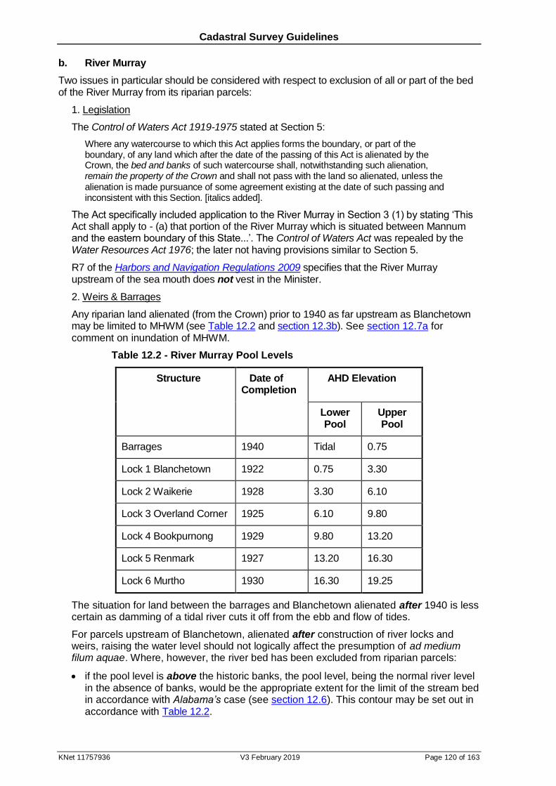
Cadastral Survey Guidelines
KNet 11757936 V3 February 2019 Page 120 of 163
b. River Murray
Two issues in particular should be considered with respect to exclusion of all or part of the bed of the River Murray from its riparian parcels:
1. Legislation
The Control of Waters Act 1919-1975 stated at Section 5:
Where any watercourse to which this Act applies forms the boundary, or part of the boundary, of any land which after the date of the passing of this Act is alienated by the Crown, the bed and banks of such watercourse shall, notwithstanding such alienation, remain the property of the Crown and shall not pass with the land so alienated, unless the alienation is made pursuance of some agreement existing at the date of such passing and inconsistent with this Section. [italics added].
The Act specifically included application to the River Murray in Section 3 (1) by stating ‘This Act shall apply to - (a) that portion of the River Murray which is situated between Mannum and the eastern boundary of this State...’. The Control of Waters Act was repealed by the Water Resources Act 1976; the later not having provisions similar to Section 5.
R7 of the Harbors and Navigation Regulations 2009 specifies that the River Murray upstream of the sea mouth does not vest in the Minister.
2. Weirs & Barrages
Any riparian land alienated (from the Crown) prior to 1940 as far upstream as Blanchetown may be limited to MHWM (see Table 12.2 and section 12.3b). See section 12.7a for comment on inundation of MHWM.
Table 12.2 - River Murray Pool Levels
Structure Date of Completion
AHD Elevation
Lower Pool
Upper Pool
Barrages 1940 Tidal 0.75
Lock 1 Blanchetown 1922 0.75 3.30
Lock 2 Waikerie 1928 3.30 6.10
Lock 3 Overland Corner 1925 6.10 9.80
Lock 4 Bookpurnong 1929 9.80 13.20
Lock 5 Renmark 1927 13.20 16.30
Lock 6 Murtho 1930 16.30 19.25
The situation for land between the barrages and Blanchetown alienated after 1940 is less certain as damming of a tidal river cuts it off from the ebb and flow of tides.
For parcels upstream of Blanchetown, alienated after construction of river locks and weirs, raising the water level should not logically affect the presumption of ad medium filum aquae. Where, however, the river bed has been excluded from riparian parcels:
if the pool level is above the historic banks, the pool level, being the normal river level in the absence of banks, would be the appropriate extent for the limit of the stream bed in accordance with Alabama’s case (see section 12.6). This contour may be set out in accordance with Table 12.2.
Cadastral Survey Guidelines
KNet 11757936 V3 February 2019 Page 121 of 163
if the historic banks are not inundated the extent of ownership of riparian parcels would be unaffected by the timing of alienation relative to weir construction.
12.7 Accretion & Erosion
For the doctrine of accretion (or erosion) to apply two factors must be present:
an ambulatory boundary, and
a gradual and imperceptible change caused naturally.
When redefining natural boundaries surveyors must assess the evidence collected to determine whether the doctrine of accretion is applicable to movement of the natural feature.
At common law where movement of a natural boundary is not gradual, natural and imperceptible the boundary becomes fixed in the position immediately prior to such movement. The surveyor must compile whatever information is available to ascertain the boundary position at that time.
The natural and imperceptible criteria require particular qualification. Discussion of this and other consequences of accretion and erosion follow.
Unintentional interference with the tidal flow led to the case Brighton and Hove General Gas Co v Hove Bungalows Ltd:
The general law of accretion applies to a gradual and imperceptible accretion to land abutting upon the foreshore brought about by the operations of nature, even though it has been unintentionally assisted by, or would not have taken place without, the erection of groynes for the purpose of protecting the shore from erosion.
The general law of accretion also applies where the natural accretion, gradual and imperceptible, abuts upon land of which the former boundary was well known and readily ascertainable. [italics added]
In the case Verrall v Nott even though the process of accretion had been facilitated by the erection of a rubble wall by Verrall it was held:
That Verrall was entitled to the benefit of any accretion to his land from the sea, although the original boundary of his land was ascertainable.
That Verrall was not prevented from taking the benefit of accretions because of the erection of the rubble wall.
Hallmann (para 13.45) also refers to the above two precedents dealing with actions leading to unintentional accretion and then confirms that:
In other cases, however, where the landowner’s acts can be shown to have been intended to cause accretion, the doctrine does not apply: A-G v Chambers (1854); A-G of Southern Nigeria v John Holt & Co. (Liverpool) Ltd (1915).
Southern Centre of Theosophy Inc v State of South Australia confirmed that the doctrine of
accretion is applicable to non tidal lakes, and that ‘...accretion may also occur where the deposits are carried by the wind, if they become settled and extend the boundary of the land into the water...’ (Hallmann para 13.44).
This judgement considered the criteria of imperceptibility in some detail. The court accepted that in certain conditions of wind and weather, movement of sand was detectable, however:
Movement of parts of the dunes, or of drifts of sand upon the dunes, is not the same thing as movement of the land boundary out into the sea. The one may be observable but does not, of its nature, constitute the other. The real question is how long it takes for a consolidation to take place bringing about a stable advance of the land.
Eligibility to accretion where the boundary was surveyed as right (straight) lines, also shown as medium high water and a fixed area given, was investigated in 1980 at North Haven. The accretion was due to the Outer Harbor Breakwater. Two international cases supported the claim:
Cadastral Survey Guidelines
KNet 11757936 V3 February 2019 Page 122 of 163
State of Penang v Ben Hon Oon. Re Lord Cross:
It is ... well settled that if the boundary of land conveyed is the line of medium high tide the mere fact that the acreage of the land conveyed is given and that the position of the line of medium high tide at the date of the conveyance can be established - whether or not it is delineated on a plan - will not prevent land which subsequently becomes dry land through the gradual and imperceptible recession of the sea from being added to the land conveyed.
Frost v Palmerston North - Kairan a River Board:
The mere fact that the original boundary has been accurately defined (such as by a reliable survey), and is still definable - will not prevent a land owner from being entitled to an accretion.
Hallmann advises (para 13.38):
Where land in a Crown grant is described as bounded by “measured lines along” the margin of a coastal “lake” (really an inlet) which is tidal, the legal opinion is that the high-water mark is intended to be the boundary, the “measured lines” merely indicating the approximate position of the high-water mark as it was at the date of grant. Such a construction would not apply, however, if the land is described as bounded by “ measured lines near” the margin or bank. Presumably, the above constructions would apply to similar descriptions relating to the seashore or to the bank of a tidal stream.
The legal principles involved where a right line, fixed boundary, inland from the coast becomes gradually submerged are somewhat obscure. See Horlin (1994) for discussion of this issue.
Willis (1974, p.14) proposes that the method for apportioning accreted lands to abutting owners depends on the facts of the case. Three methods referred to are:
1. prolonging the side boundaries,
2. joining the previous terminus of the side boundary to the new riparian boundary such that it intersects the new riparian boundary at a right angle, or
3. give to each owner a share of the new shore line in proportion to what was held in the old shore line.
Refer to Willis for a fuller explanation and examples.
a. River Murray - Effect of the Weirs and Barrages
The construction of the locks and barrages along the River Murray has complicated boundary redefinitions in the area. The barrages have had a significant effect in the low lying areas around Lakes Alexandrina and Albert. In many instances the intentionally raised river level is above the old limit of the lake or river bed meaning the doctrine of accretion is not applicable and the now fixed boundary is lost. That is, the extent of tidal influence is no longer evident and the historic bank of the river is permanently submerged.
The locks and weirs have caused only minor inundation upstream and may not have raised the river level above the original river bank. If so, the riparian boundary probably remains ambulatory and locatable.
In areas of inundation there are various methods for determining the position of the historical limit of the river bed, either to enable delineation of a lost boundary or to determine if the historic bank is still above water. Some of these methods are outlined below:
1. By Survey
Many of the original surveys of the river located the edge by line and offset. This position may be re-established from a combination of the original surveyors field work and physical evidence of the boundaries.
2. By Vegetation
In a number of areas, particularly in the lower reaches, considerable inundation of lands adjacent to the river has been caused by the construction of the barrages. In some of these areas a line of trees are found at the edge of the historical bank.
Cadastral Survey Guidelines
KNet 11757936 V3 February 2019 Page 123 of 163
3. From Records Held by SA Water
In the years around 1907, the old EWS Department undertook a detailed topographic survey of the River Murray; numerous cross sections were taken. These records contain some information regarding the position of the bank and river both horizontally and vertically and could provide assistance in redefinition of the river banks in some areas. Contact the Dams & Civil Unit of the Engineering Group of SA Water.
4. By Scale and Plot
In cases where no other evidence exists the historic edge of river can be fixed by scaling from the original survey plan.
12.8 The Waterfront Reserve/Road Boundary
In 1835, prior to his departure for South Australia, Colonel Light was instructed in all surveys to reserve as public roads all land within a certain width of the coast, each side of navigable rivers, and around lakes.
Initially most waterfront roads were fixed during survey of abutting Sections with the landward boundary parallel to and 150 (or 100) links from the waterfront. Colonel Light’s instructions were not always uniformly applied and many grants were made with waterfrontages, provision of the roads not continuing to the same extent after about 1845.
Whenever the first opportunity arose after 1898 to dispose of parcels by grant or offer for lease, provision was made for a reserve along the coast and River Murray. In most cases the landward boundary of this reserve was not surveyed, but was merely delineated on existing survey records as a broken line. Very few were dedicated as public roads, and they eventually became known as the 150 link reserve. They were not reserves in the sense of having been reserved or dedicated under the Crown Lands Act, but were simply areas of Crown land.
In the 1970s concern by the Surveyor-General about the status of the boundary between the 150 link reserve and adjacent land led to a legal opinion that it was necessary in each case to consider the terms of the land grant, or certificate of title, as to the nature of the boundaries so granted41.
In the majority of cases the reservation of waterfront land operated as an exception to the land granted. Even though the term ‘150 link reserve’ implied an ambulatory inland boundary it was opined that this would be an unusual step, the usual course being the immediate and permanent fixing of boundaries at the date of the exception. Due to the complexity of the matter the Surveyor-General was advised against the issue of a general direction to surveyors.
An example of the reservation by exception is given in the case McGrath v Williams:
The plaintiff claimed to be the owner in fee simple of a piece of land fronting on the north of Shoalhaven River, which is tidal. The land in question was granted by the Crown in 1843 to plaintiff's predecessors in title. The grant was subject to certain reservations, including a reservation of “all land within one hundred feet of high-water mark on the sea coast, and on every creek, harbour and inlet of the sea.” The plaintiff sought to bring the land down to high-water mark on the Shoalhaven River, under the Real Property Act, claiming that the hundred feet reservation had been eroded away. The Crown objected to the plaintiff's application on the ground that the reservation in the grant enabled the Crown at any time to take possession of a hundred feet from the existing high-water mark at the time of such taking of possession.
41In a minority of cases the reservation operates as a defeasance, expressing the grant as being subject to a public right of
way 150 links wide adjoining the coast. The grant retains contingency with the sea/river and the right of way is an ambulatory ribbon 150 links wide.
Cadastral Survey Guidelines
KNet 11757936 V3 February 2019 Page 124 of 163
Held, that the reservation operated by way of exception from the grant, and that consequently the hundred feet must be measured from high-water mark as at the date of the grant.
Similar relevant cases on reservation by exception are found in Smith v Renwick and A-G v Dixon.
Accurate determination of the MHWM or river edge is essential to determining the landward boundary of the reserve. This landward boundary was not directly fixed by survey, it was not marked on the ground so that it could be fenced, and it generally cannot be relocated by directly retracing the surveyors measurements, as there are none.
The date of creation of the 150 link reserve may be obtained from withdrawn Hundred Plans located at the Public Search Counter of the LTRO. The date the land was leased from the Crown can be found in the Crown Lease books held by the Registrar-General.
For new or widened reserve requirements see section 8.4.
a. Coastal Reserves
Determining the landward boundary of the coastal reserve can be a difficult task where there has been natural and imperceptible movement of the MHWM. Often the original survey was carried out some time before delineation of the reserve, which in turn may have been some time prior to alienation/exception. Consequently there is no record of the position of the MHWM at the time of exception of the 150 links.
One method of determining this landward boundary is as follows:
1. plot the high water mark located by the original survey.
2. using one of the methods in section 12.4, determine and plot the present MHWM.
3. from records held in the LTRO, determine the date the land adjacent to the coastal reserve was alienated.
4. determine the position of the MHWM at the time of alienation by proportioning between the original and present determination of the MHWM.
5. set out a line 150 links back from the position derived for the MHWM at step 442.
b. River Murray Reserves
Surveys adjacent to the River Murray commenced in the 1840s, initially around Lake Alexandrina. By 1870 most of the Hundreds up to Morgan had been surveyed. Surveys between Morgan and the State border were completed by 1920. The definition of the landward boundary of the 150 link reserve is the main problem facing surveyors re-establishing boundaries adjacent to the River Murray due to the affect on the river of the construction of the weirs and barrages:
In some cases the historic edge of the river (see sections 12.6 and 12.6b2) will have been inundated. Parcels alienated prior to the construction should be located 150 links from a point as determined by one of the methods described in section 12.7a.
On the other hand, inundation of the historic edge of the river where alienation occurred after construction would be treated differently. Consistent with the principles in Yeomans v Peter (section 12.6a), the landward boundary of the reserve is considered to be 150 links
from pool level. This can be measured from a contour set out in accordance with Table 12.2.
42 An example of this process is seen on DBP 52, Hundred of Carribie.
Cadastral Survey Guidelines
KNet 11757936 V3 February 2019 Page 125 of 163
The timing of alienation in relation to construction would be irrelevant where the historic bank43 has not been inundated; the 150 links should be measured from the bank at the time of alienation/exception.
12.9 References & Bibliography
The following list contains information relevant to natural boundary law. While far from exhaustive it does provide a range of reference material. Not all will be specifically relevant to the South Australian system.
Books & Articles
Butt (1995), The Laws of Australia, The Law Book Co.
Brown (1980), Law Relating to Land Boundaries and Surveying, Association of Consulting Surveyors, Queensland.
Hallmann (2nd edition, 1994), Legal Aspects of Boundary Surveying as apply in New South Wales, The Institution of Surveyors, Australia, New South Wales Division.
Halsbury’s (1998), Laws of Australia.
Horlin (1994), Submerged Boundaries, The Australian Surveyor, Vol.39 pp40-45.
Manual of the NSW Integrated Survey Grid (1976), NSW Department of Lands.
Moore (1968), Land by the Water, The Australian Law Journal, Vol.41 pp532-542.
Weidener (1979), Surveying the Tidal Boundary, Surveying and Mapping, Vol.39 pp333-342.
Willis (1974), Notes on Survey Examination, NSW Registrar-General’s Department.
Judgements
A-G v Chambers (1854) 43 ER 486
A-G v Dixon (1904) 273 AC 277
A-G of Southern Nigeria v John Holt & Co (Liverpool) Ltd (1915) AC 599
Brighton and Hove General Gas Co v Hove Bungalows Ltd (1924) 1 Ch 372
Frost v Palmerston North - Kairan a River Board (1916) NZLR 643
Kingdon v Hutt River Board (1905) 25 NZLR 145
Lanyon Pty Ltd v Canberra Washed Sand Pty Ltd (1966) 115 CLR 342
McGrath v Williams (1912) 12 SR (NSW) 447
Raven v Keane (1920) GLR 168
Smith v Renwick (1882) 3 LR (NSW) 398
Southern Centre of Theosophy Inc v State of South Australia (1982) AC 706
State of Alabama v State of Georgia (1859) 64 US 515
State of Penang v Ben Hon Oon (1971) 3 A11 ER 1163
Verral v Nott (1939) 39 SR (NSW) 89
Yeomans v Peter (1895) 16 NSWR (Eq) 197
43 It is assumed historic edges determined as MHWM, above the barrages, have been inundated.

Cadastral Survey Guidelines
KNet 11757936 V3 February 2019 Page 126 of 163
Case Reference Abbreviations
AC English Law Reports, Appeal Cases
CLR Commonwealth Law Reports
Ch Chancery 1891-
ER English Reports
GLR Gazette Law Reports (NZ)
LR Law Reports
NSWR NSW Reports 1960-1970
NZLR New Zealand Law Reports
SR State Reports
US United States Supreme Court Reports Lawyers Edition 1754-1956
Cadastral Survey Guidelines
KNet 11757936 V3 February 2019 Page 127 of 163
13 Survey Accuracies
13.1 Introduction
The aim of the required accuracy tolerances is to ensure there is confidence in the location and extent of peoples’ interest in land. Objectives include:
boundary data and its position of survey marks and existing improvements meet appropriate standards
errors found in the position of survey control marks are reported and appropriately corrected.
13.2 Controlling Legislation
Survey Regulations 2007 state at regulation 16:
(1) A surveyor must, in carrying out a cadastral survey-
(a) ensure the survey meets the following standards of accuracy:
(i) the perimeter misclosure of the survey must not exceed the tolerances fixed by directions issued by the Surveyor-General.
(ii) if the survey is connected to permanent or State survey marks (and linear misclosure and displacement may be tested) - the linear misclosure of the survey and the linear displacement (caused by angular misclosure) between the survey and the relevant Map Grid of Australia coordinates must not exceed the tolerances fixed by directions issued by the Surveyor-General.
(iii) if the survey is carried out using coordinate based techniques or verified radiations (where linear misclosure and displacement cannot be tested) and the survey is connected to permanent or State survey marks the Map Grid of Australia coordinates of which are known - the difference in the position of survey marks as placed or accepted in the survey and the position of those marks as determined from their Map Grid of Australia coordinates must not exceed the tolerances fixed by directions issued by the Surveyor-General.
(iv) if the survey is carried out using coordinate based techniques or verified radiations (where linear misclosure and displacement cannot be tested) and the survey is connected to permanent or State survey marks the Map Grid of Australia coordinates of which are not known - the difference in the position of survey marks as placed or accepted in the survey and the position of those marks as determined from the measurements shown on the plan (including measurements relating to the State survey marks) must not exceed the tolerances fixed by directions issued by the Surveyor-General.
(b) use equipment and techniques that will enable the required standard of accuracy to be met;
and
(c) carry out adequate checks of the survey to ensure that the required standard of accuracy is met.
(2) A surveyor must provide the Surveyor-General with satisfactory evidence of compliance with subregulation (1) in relation to a specified cadastral survey within 14 days of receiving a written request from the Surveyor-General for such evidence (or such longer period as is allowed by the Surveyor-General).
SGD1 fixes the standards of accuracy; these are summarised in Table 13.1 below.
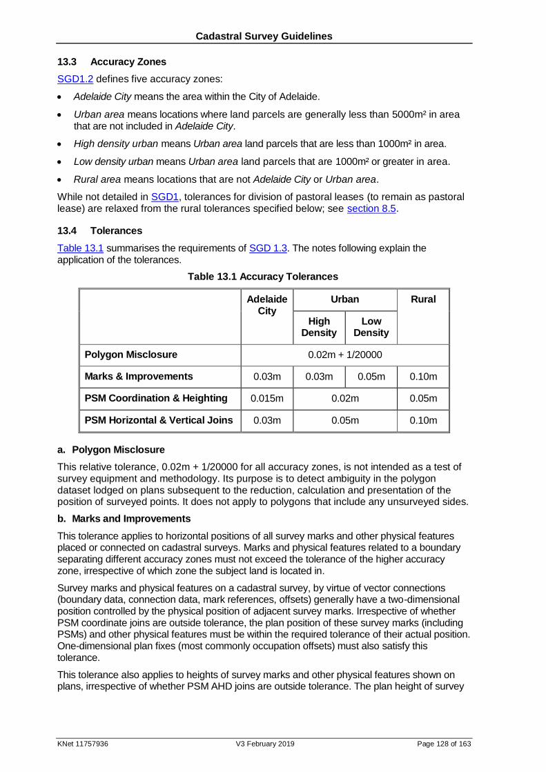
Cadastral Survey Guidelines
KNet 11757936 V3 February 2019 Page 128 of 163
13.3 Accuracy Zones
SGD1.2 defines five accuracy zones:
Adelaide City means the area within the City of Adelaide.
Urban area means locations where land parcels are generally less than 5000m² in area that are not included in Adelaide City.
High density urban means Urban area land parcels that are less than 1000m² in area.
Low density urban means Urban area land parcels that are 1000m² or greater in area.
Rural area means locations that are not Adelaide City or Urban area.
While not detailed in SGD1, tolerances for division of pastoral leases (to remain as pastoral lease) are relaxed from the rural tolerances specified below; see section 8.5.
13.4 Tolerances
Table 13.1 summarises the requirements of SGD 1.3. The notes following explain the application of the tolerances.
Table 13.1 Accuracy Tolerances
Adelaide City
Urban Rural
High Density
Low Density
Polygon Misclosure 0.02m + 1/20000
Marks & Improvements 0.03m 0.03m 0.05m 0.10m
PSM Coordination & Heighting 0.015m 0.02m 0.05m
PSM Horizontal & Vertical Joins 0.03m 0.05m 0.10m
a. Polygon Misclosure
This relative tolerance, 0.02m + 1/20000 for all accuracy zones, is not intended as a test of survey equipment and methodology. Its purpose is to detect ambiguity in the polygon dataset lodged on plans subsequent to the reduction, calculation and presentation of the position of surveyed points. It does not apply to polygons that include any unsurveyed sides.
b. Marks and Improvements
This tolerance applies to horizontal positions of all survey marks and other physical features placed or connected on cadastral surveys. Marks and physical features related to a boundary separating different accuracy zones must not exceed the tolerance of the higher accuracy zone, irrespective of which zone the subject land is located in.
Survey marks and physical features on a cadastral survey, by virtue of vector connections (boundary data, connection data, mark references, offsets) generally have a two-dimensional position controlled by the physical position of adjacent survey marks. Irrespective of whether PSM coordinate joins are outside tolerance, the plan position of these survey marks (including PSMs) and other physical features must be within the required tolerance of their actual position. One-dimensional plan fixes (most commonly occupation offsets) must also satisfy this tolerance.
This tolerance also applies to heights of survey marks and other physical features shown on plans, irrespective of whether PSM AHD joins are outside tolerance. The plan height of survey

Cadastral Survey Guidelines
KNet 11757936 V3 February 2019 Page 129 of 163
marks (including PSMs) and other physical features must be within the required tolerance of their actual height, relative to adjacent PSMs referred to on the plan as providing height control.
c. PSM Coordination & Heighting
This positional tolerance applies to PSM coordinates (including heights if relevant) provided by surveyors for new, previously uncoordinated, and re-coordinated PSMs. The coordinates provided must be within the required tolerance of the actual position of the PSM, relative to existing survey control marks (see sections 2.4 and 13.5 for explanation of survey uncertainty). In the coordination of PSMs surveyors must be able to demonstrate sound control, that is, ‘whole to part’ interpolation adjusted to surrounding control, not extrapolation from control. See section 2.5 for information regarding provision of these coordinates.
d. PSM Horizontal & Vertical Joins
Surveys in all areas, not just DSAs, must be connect and orientated to the current published or established (see SGD 2.3.3) MGA2020 coordinates of two survey marks straddling the survey. The two marks selected for this orientation must be far enough apart to minimise the contribution of extrapolation errors in bearing comparisons to other PSMs and SSMs. PSMs nominated as the bearing datum derivation for all certified surveys must be within 10 seconds of MGA2020.
This relative tolerance applies to the surveyed difference to published PSM coordinates for:
distance between PSMs,
lateral displacement caused by bearing difference between PSMs, and
height difference between PSMs.
Application of this tolerance is only intended for successive PSMs at normal spacings (see section 14.3b1 & 14.3b2) in all directions from any PSM. It is also intended for testing of any other intermediate PSMs located within these spacings. It is not intended for testing between all combinations of PSM pairs on a survey. For example, it is not intended to be tested on two PSMs 450m apart in an urban area if there is another PSM about halfway between them.
PSM coordinates provide an opportunity for surveyors to verify their surveys’ closure. Where this check fails through apparent coordinate or height discrepancies surveyors must:
verify their survey observations are correct by some other means,
identify the PSM(s) whose coordinates or heights appear to be the cause of the relative tolerance being exceeded, and in regard to the PSM(s) identified:
1. not adjust their survey to their coordinates/heights,
2. re-coordinate/re-height them (see section 2.5),
3. provide the new coordinates using the template for the provision of permanent survey mark coordinates and complete an online coordinate error report form, certified by the licensed surveyor certifying the survey, and at the survey’s lodgement (see section 2.7),
Reporting in item 3 above is not necessary for PSMs with coordinate/height PUs greater than 0.02m in Adelaide City, 0.05m in other urban areas, 0.10m in rural areas or where “Type B PU”
(see section 2.4) has been designated (their inaccuracy is already known). It is also not required for PSMs connected on plans for information purposes.
13.5 Survey Specifications
In Standard for the Australian Survey Control Network (SP1) Uncertainty means: “Doubt
about the validity of a measurement or result of a measurement (e.g. a coordinate). It is an indication of how wrong a value may be and is used to quantify the level of survey quality. Uncertainty is expressed as a standard deviation in the International System of Units (SI) expanded to the 95% confidence level.”
Cadastral Survey Guidelines
KNet 11757936 V3 February 2019 Page 130 of 163
SP1 defines SU (Survey Uncertainty) as: “The uncertainty of the horizontal and/or vertical coordinates of a survey control mark independent of datum. That is, the uncertainty of a coordinate relative to the survey in which it was observed, without the contribution of the uncertainty in the underlying datum realisation.”
SP1 defines RU (Relative Uncertainty) as: “The uncertainty between the horizontal and/or vertical coordinates of any two survey control marks. RU can be expressed in SI units at the 95% confidence level, or in a proportional form such as a ratio of uncertainty per unit length or survey misclosure.”
SP1 refers to SUs and RUs in terms of survey control marks; the tolerances for measuring all marks and improvements require the same approach in design of survey specifications. SP1’s reference to coordinates as “result of a measurement” similarly applies to positions instead expressed through a series of vectors. Positional tolerances are deemed to be relative to the survey’s PSMs (irrespective of coordination) and other marks that control the adjacent cadastre. These marks must also meet the positional tolerance with respect to each other.
While SU & RU are defined at the 95% confidence level, tolerances expressed in survey instructions are an outer limit. The regulations require surveyors to use equipment and techniques to enable the required standard of accuracy to be met (see also sections 2.4 and 2.6). They also require surveyors to carry out adequate checks to ensure that the required
standard of accuracy is met. For guidance on survey specifications to achieve varying levels of SU and RU see SP1’s Guidelines for:
Conventional Traverse Surveys
Control Surveys by GNSS
Control Surveys by Differential Levelling
Adjustment and Evaluation of Survey Control
13.6 Reliability
While cadastral tolerances are generally comfortably met by surveyors given their management of systematic and random errors, gross errors at different stages of data collection and management may remain undetected unless independent check observations are made. The regulations require surveyors to provide the Surveyor-General, on request, with satisfactory evidence of compliance with this requirement:
surveyors detecting discrepancies in PSM horizontal, or AHD, joins must verify their survey through appropriate redundant observations. It is not sufficient to merely recalculate survey that has no redundancy.
surveyors are only able to ensure that their surveyed positions of marks and improvements (including vertical if so fixed) do not exceed tolerances through appropriate redundant observations, or comparison with positions recorded on previous surveys.
similarly, surveyors are only able to ensure that they do not exceed tolerances for coordination of PSMs through appropriate redundant observations.
13.7 Occupation
Where occupation is unambiguous, for example the sharp corner of a wall or the face of a colourbond fence along a road alignment, it is expected that the tolerances in Table 13.1 are met. However, the ambiguous nature of much occupation means that their plan location will be subject to this ambiguity. For example, if a fence is shown as being ‘on’ a side boundary it is expected that the boundary passes within tolerance of the fence material.
To reduce ambiguity caused by the leaning of occupation, unless stated otherwise, it is assumed that the occupation has been located at the lowest accessible height.
Cadastral Survey Guidelines
KNet 11757936 V3 February 2019 Page 131 of 163
14 Marking Requirements for Surveys
14.1 Introduction
In determining the marking requirements for a cadastral survey the surveyor must meet the requirements of the survey instructions irrespective of their client’s needs or wishes. Marking of unlodged identification surveys is optional.
The aim of these survey instructions is to ensure that the location and extent of peoples’ interest in land is readily identifiable. In the short term this includes land purchasers, not just the surveyor’s client. In the longer term it means that both new and existing boundaries defined in the survey may be later resurveyed as an unambiguous technical exercise. General objectives in meeting this aim are:
New boundaries must be pegged.
Sufficient PSMs must be placed, connected and protected to enable land parcel boundaries to be readily resurveyed, allowing for redundancy in resurvey, and potential disturbance of some PSMs.
PSM protection shall include coordination of their position.
Sufficient PSMs must be available in subdivisions from the commencement of building construction to enable any surveyor to readily resurvey parcels.
The exception from final placement of survey marks in the certification (SGD3) only applies to final marking of divisions into more than five allotments. All other surveys must strike out this exception.
As community divisions are a cadastral survey they must fulfil the marking requirements of the survey instructions, consistent with other land division.
The following may not provide flexibility surveyors require in unusual circumstances; surveyors are reminded of the procedure for seeking exemption from survey instructions (see section 1.3).
14.2 Controlling Legislation
Authority for marking land boundaries is found in the Survey Act, Regulations and SGD2. Section 43 of the Survey Act 1992 provides:
43 - Survey Instructions
(1) The Governor may, by regulation, issue survey instructions in relation to cadastral surveys and records of cadastral surveys.
(2) Without limiting the generality of subsection (1), survey instructions may-
(d) regulate the form, establishment, custody, maintenance, removal or reinstatement of survey marks;
Survey Regulations 2007 defines the terms:
12 - Survey marks
For the purpose of the Act and these regulations, State survey marks and survey pegs are specified as survey marks.1
Note –
1Permanent survey marks are included within the definition of survey mark in section 4 of the Act.
The marking provisions of SGD2 apply to all cadastral surveys for which plans are lodged in
the Lands Titles Office, except for plans for information purposes (PPG 2.24.3 requires at
least two PSMs for the latter).
Cadastral Survey Guidelines
KNet 11757936 V3 February 2019 Page 132 of 163
SGD 2.3 restricts where some types of PSMs may be used and that brass plaques shall be
used on conventional PSMs placed. It specifies PSM numbers and spacings, protection, and
coordination (including heights if relevant).
SGD 2.4 approves survey peg and reference mark types for different circumstances, and
specifies other requirements of pegging.
14.3 Permanent and State Survey Marks
a. Interpretation
This section will differentiate between PSMs and SSMs according to their respective interpretations under the Survey Act and Regulations where it is necessary to avoid confusion.
PSMs are the marks historically referred to as Network PSMs and will continue to be identified
by the symbol:
The following have been gazetted as PSMs pursuant to section 49(3) of the Act:
1. a below ground permanent survey mark being a brass plaque inscribed survey mark or a steel rod measuring at least 300 millimetres in length and 10 millimetres in diameter set in a concrete block measuring at least 150 millimetres square at the top, 250 millimetres square at the base and 300 millimetres in depth.
2. an above ground permanent survey mark being a brass plaque inscribed survey mark or a metal rod set in a concrete pillar firmly secured in the ground.
3. stainless steel pins, at least 50mm long and 5mm in diameter, with inscribed washer suitable for permanent installation in concrete.
The last of these, mini PSMs, are restricted to placement in subdivisions of more than 5 allotments and community divisions (see section 14.3b3 and 14.3c).
PSMs historically may have had other acceptable specifications; this does not alter their status as PSMs.
The following marks are defined as State survey marks at Regulation 10:
State survey mark means-
(a) a brass plaque inscribed survey mark set in a concrete block measuring at least 150 millimetres square on the top, 250 millimetres square at the base and 300 millimetres in depth; or
(b) a beacon being a wooden or metal tripod or quadripod fixed to the ground, or a stone cairn supporting a wooden, metal or plastic vane or cap, constructed for survey observations; or
(c) any other mark approved by the Surveyor-General as a State survey mark permanently placed on land for use in surveying.
SSMs are the marks previously referred to either as non-Network PSMs (in network areas) or
PSMs outside network areas; they shall be identified by the symbol:
b. Density & Spacing
PSMs shall be placed adjacent to road intersections or bends, within the road corridor. They may also be required at internal (off road) corners in rural areas.
SGD 2.3.1.1 requires that surveys not connected to at least three PSMs and/or SSMs need to place additional PSMs (so that they are connected to at least three). If any two or more of the PSMs or SSMs are within a 100m radius of each other in urban areas, or within a 500m radius
Cadastral Survey Guidelines
KNet 11757936 V3 February 2019 Page 133 of 163
of each other in rural areas, they shall count as only one PSM for the purposes of this requirement.
If existing or new PSMs connected do not provide sound positional control for the boundaries being surveyed then additional PSMs shall be placed; the PSMs should straddle the survey, not all being to one side of those boundaries.
Desired PSM spacing aims to facilitate future survey from any allotment/lot (think in terms of the most inaccessible land parcel) to its controlling PSMs. SGD 2.3.1.2 requires 200m urban or 2000m rural PSM spacings, meaning that the survey may require more than the minimum three PSMs. Unless otherwise specified these spacings are along road routes surveyed and must be satisfied for all direct road routes between successive PSMs. Given the variety of road designs and topography it is impracticable to insist these spacings be met in all cases. Accordingly, the following guidelines shall be used in applying the 200m/2000m spacings; exemption should be sought if there are sound reasons for more flexibility.
1. Urban
Due to the policy when the tertiary network was surveyed it is generally not necessary to increase the existing density of PSMs in urban areas of DSAs. New PSMs, however, may be required:
for divisions into more than five allotments/lots (see 3 below),
to replace PSMs disturbed, or threatened with destruction, and
outside DSAs.
In applying the urban PSM spacings:
Rather than placing PSMs short of a road junction or bend, it is preferable to extend PSM spacing, to a maximum of 300m, to enable the placement of a PSM at a logical (given position of other PSMs) road junction or bend.
Where the distance along a straight road between road intersections or bends exceeds 300m the PSM spacing may be extended to the next road intersection or bend, provided the spacing does not exceed 500m.
PSMs should be staggered in the road framework such that no large expanses remain uncontrolled; any road longer than 150m, whether straight or through its bends and intersections, should have at least one PSM.
Cul-de-sacs more than 75m long should have a PSM at its closed end. This requirement may be ignored if the end of the cul-de-sac opens onto a reserve providing survey access to a suitable PSM.
Meeting the above guidelines may mean that some PSM spacings are significantly less than 200m.
2. Rural
It is generally not necessary to increase the existing density of PSMs in DSAs numbered below 500. New PSMs, however, may be required:
outside DSAs,
in DSAs numbered above 500,
for divisions into more than five allotments/lots (see 3 below), or
to replace PSMs disturbed, or threatened with destruction.
In applying the rural PSM spacings:
Where the distance between road intersections or bends exceeds 2000m the spacing between PSMs may be extended to the next road intersection or bend. If this increases

Cadastral Survey Guidelines
KNet 11757936 V3 February 2019 Page 134 of 163
to more than 3000m then a PSM should be placed adjacent to an available side boundary intersection with either side of the road.
Where any surveyed internal (off road) boundary corner is not within a 3000m radius of
any existing or new PSM connected then additional PSM(s) must be placed, generally adjacent to an internal boundary corner.
Meeting the above guidelines may mean that some PSM spacings are significantly less than 2000m.
It is recognised that other surveys’ (such as pastoral lease division) terrain, parcel size and road configurations may justify seeking exemption from the above PSM criteria.
3. Subdivisions and Infrastructure Projects
For all divisions of land into more than five allotments/lots, the Surveyor-General’s Survey Operations Unit (see Contact Details) shall advise of new PSM locations prior to plan lodgement (consistent with above requirements). PSMs may also be required in common property access roads in community divisions, as for roads in other land division, however note the option to use mini PSMs in kerbs (see section 14.3a, c & d).
Surveyors are also responsible for PSM replacement on infrastructure projects where PSMs are disturbed or threatened; they must discuss this replacement with the Surveyor-General’s Survey Operations Unit (see Contact Details) prior to construction.
Subdivisions may have control weakness for subsequent surveyors (particularly in the short term) due to delays in final placement of conventional PSMs, desired PSM density reliant on future stages, and cul-de-sac road design. To alleviate this weakness mini PSMs (see section 14.3a & d) placed in kerbs (or other substantial concrete, not footpaths) are to supplement the conventional PSM network. The aim is to have the mini PSMs in place by the time purchasers may wish to erect improvements. In most cases it is expected the mini PSMs will be in place at plan lodgement. Unless conventional PSMs are proposed to be placed in these locations, mini PSMs shall be placed on subdivisions at the:
stage truncation of all roads, and
closed end of all cul-de-sacs longer than 30m. This requirement may be ignored if the end of the cul-de-sac opens onto a reserve providing survey access to a suitable PSM.
Generally there should be a total of at least two new PSMs (conventional or mini) on the roads internal to each subdivision stage. Despite the use of mini PSMs, a basic network of conventional PSMs is still ultimately required over the whole development. The use of mini PSMs may justify a reduction in the overall number of conventional PSMs otherwise required in the development, however this will not necessarily be on a one-for-one basis.
c. Siting
PSMs represent the prime physical evidence of cadastral boundaries. Their long term retention is of benefit to the community by facilitating unambiguous redefinition of boundaries and a reduction in future survey costs. It is therefore essential that the selection and siting of PSMs used on a survey be undertaken with a view to both their long term protection and ease of future connection. The following factors are relevant to site selection:
within urban areas, the non-common trench side of roads
at road bends, on the outside of the curve
clear of fencing operations, or foreseeable earth or construction work
when placed near internal boundaries, adjacent to an occupied bend or boundary intersection
direct traverse occupation of the mark
clear GNSS observation, and
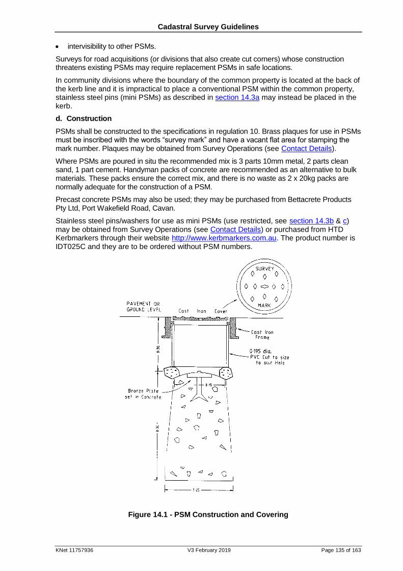
Cadastral Survey Guidelines
KNet 11757936 V3 February 2019 Page 135 of 163
intervisibility to other PSMs.
Surveys for road acquisitions (or divisions that also create cut corners) whose construction threatens existing PSMs may require replacement PSMs in safe locations.
In community divisions where the boundary of the common property is located at the back of the kerb line and it is impractical to place a conventional PSM within the common property, stainless steel pins (mini PSMs) as described in section 14.3a may instead be placed in the kerb.
d. Construction
PSMs shall be constructed to the specifications in regulation 10. Brass plaques for use in PSMs must be inscribed with the words “survey mark” and have a vacant flat area for stamping the mark number. Plaques may be obtained from Survey Operations (see Contact Details).
Where PSMs are poured in situ the recommended mix is 3 parts 10mm metal, 2 parts clean sand, 1 part cement. Handyman packs of concrete are recommended as an alternative to bulk materials. These packs ensure the correct mix, and there is no waste as 2 x 20kg packs are normally adequate for the construction of a PSM.
Precast concrete PSMs may also be used; they may be purchased from Bettacrete Products Pty Ltd, Port Wakefield Road, Cavan.
Stainless steel pins/washers for use as mini PSMs (use restricted, see section 14.3b & c) may be obtained from Survey Operations (see Contact Details) or purchased from HTD Kerbmarkers through their website http://www.kerbmarkers.com.au. The product number is IDT025C and they are to be ordered without PSM numbers.
Figure 14.1 - PSM Construction and Covering
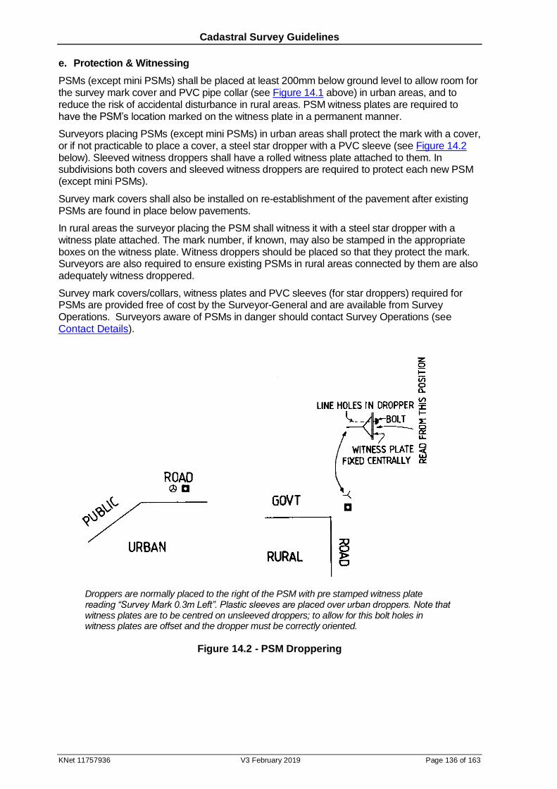
Cadastral Survey Guidelines
KNet 11757936 V3 February 2019 Page 136 of 163
e. Protection & Witnessing
PSMs (except mini PSMs) shall be placed at least 200mm below ground level to allow room for the survey mark cover and PVC pipe collar (see Figure 14.1 above) in urban areas, and to reduce the risk of accidental disturbance in rural areas. PSM witness plates are required to have the PSM’s location marked on the witness plate in a permanent manner.
Surveyors placing PSMs (except mini PSMs) in urban areas shall protect the mark with a cover, or if not practicable to place a cover, a steel star dropper with a PVC sleeve (see Figure 14.2 below). Sleeved witness droppers shall have a rolled witness plate attached to them. In subdivisions both covers and sleeved witness droppers are required to protect each new PSM (except mini PSMs).
Survey mark covers shall also be installed on re-establishment of the pavement after existing PSMs are found in place below pavements.
In rural areas the surveyor placing the PSM shall witness it with a steel star dropper with a witness plate attached. The mark number, if known, may also be stamped in the appropriate boxes on the witness plate. Witness droppers should be placed so that they protect the mark. Surveyors are also required to ensure existing PSMs in rural areas connected by them are also adequately witness droppered.
Survey mark covers/collars, witness plates and PVC sleeves (for star droppers) required for PSMs are provided free of cost by the Surveyor-General and are available from Survey Operations. Surveyors aware of PSMs in danger should contact Survey Operations (see Contact Details).
Droppers are normally placed to the right of the PSM with pre stamped witness plate reading “Survey Mark 0.3m Left”. Plastic sleeves are placed over urban droppers. Note that witness plates are to be centred on unsleeved droppers; to allow for this bolt holes in witness plates are offset and the dropper must be correctly oriented.
Figure 14.2 - PSM Droppering
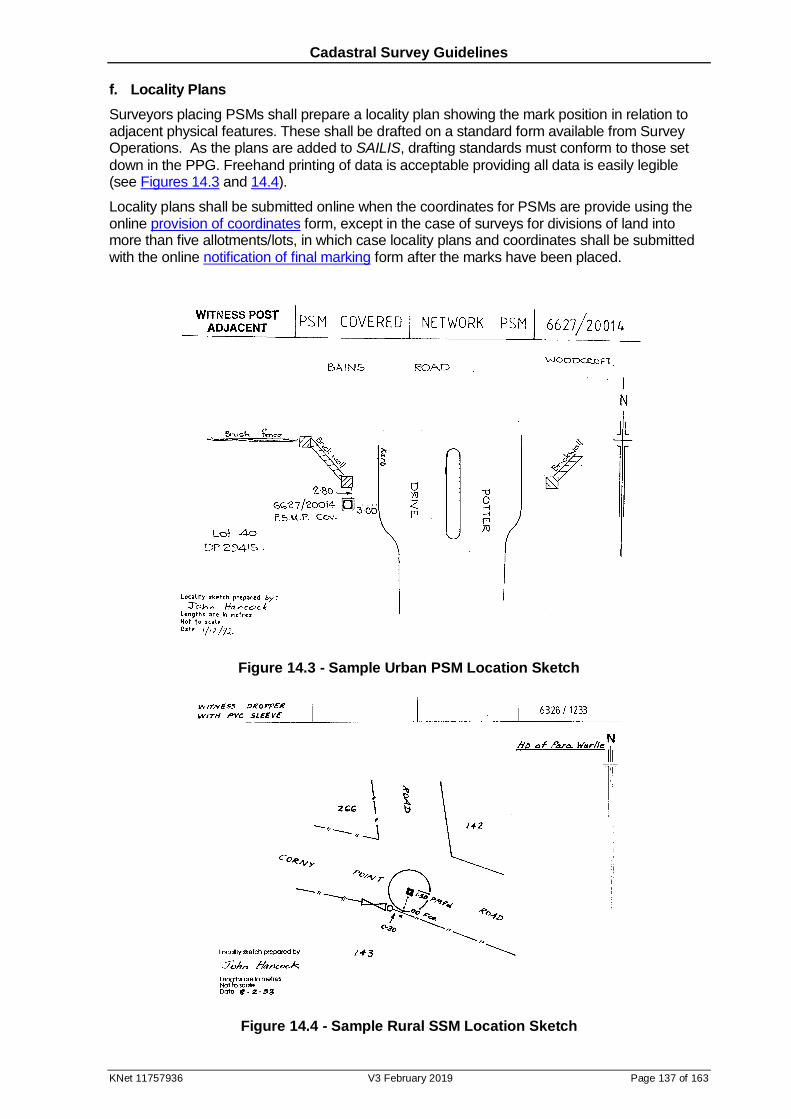
Cadastral Survey Guidelines
KNet 11757936 V3 February 2019 Page 137 of 163
f. Locality Plans
Surveyors placing PSMs shall prepare a locality plan showing the mark position in relation to adjacent physical features. These shall be drafted on a standard form available from Survey Operations. As the plans are added to SAILIS, drafting standards must conform to those set
down in the PPG. Freehand printing of data is acceptable providing all data is easily legible (see Figures 14.3 and 14.4).
Locality plans shall be submitted online when the coordinates for PSMs are provide using the online provision of coordinates form, except in the case of surveys for divisions of land into more than five allotments/lots, in which case locality plans and coordinates shall be submitted with the online notification of final marking form after the marks have been placed.
Figure 14.3 - Sample Urban PSM Location Sketch
Figure 14.4 - Sample Rural SSM Location Sketch

Cadastral Survey Guidelines
KNet 11757936 V3 February 2019 Page 138 of 163
g. Coordination
Surveyors placing PSMs and connecting some existing PSMs are required to determine the MGA2020 coordinates of those PSMs (and/or heights if relevant) and provide them to the Surveyor-General using the template for the provision of permanent survey mark coordinates. Relevant procedures and specifications are detailed in sections 2.5 and 13.4.
14.4 Survey Pegs
a. Specifications
Regulation 10 and SGD 2.4 approve the following mark types as survey pegs:
1. pegging, coloured white, directly of the actual boundary corner, not offset to the boundary:
peg of a durable nature, composed of wood, metal, plastic or other material approved for the purpose by the Surveyor-General, measuring at least 300 millimetres in length and 50 millimetres square at the top
metal rod at least 300 millimetres in length and at least 10 millimetres in diameter to which is mounted a metal or plastic top of durable material, at least 50 millimetres square
star dropper of at least 300 millimetres in length.
2. where it is not practicable to drive a survey peg of the above types due to improvements covering the actual boundary corner, the following marks, coloured white, may be inserted into those improvements directly at the actual boundary corner, not offset to the boundary:
galvanised iron nail driven into a timber fence
masonry nail or screw secured into a wall or pavement
deck spike at least 100 millimetres in length and 8 millimetres in diameter driven into bitumen.
3. where it is not practicable to directly peg the actual boundary corner; instead a position offset to the boundary corner is to be pegged (not coloured white) with a:
metal pipe or rod at least 300 millimetres in length and at least 10 millimetres in diameter
star dropper at least 300 millimetres in length.
b. Marking of Boundaries
Regulation 13 prescribes the boundary marking requirements for cadastral surveys:
13 - Placing or accepting survey marks
(1) A surveyor must, in carrying out a cadastral survey-
(a) ensure that each new boundary of the land is marked with survey pegs, or if that is not practicable, reference marks so that the boundary is readily and unambiguously discernible on the ground after completion of the survey; and
(b) mark each boundary of the land in accordance with any applicable directions issued by the Surveyor-General; and
(c) if a reference mark is placed or accepted in the survey – note on the plan of survey the type of mark used.
While the marking of existing boundaries is optional, regulation 13 (1)(a) requires all new boundaries to be pegged. The actual corner must be directly marked with a survey peg unless:
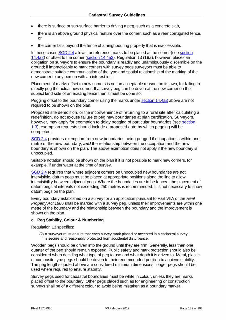
Cadastral Survey Guidelines
KNet 11757936 V3 February 2019 Page 139 of 163
there is surface or sub-surface barrier to driving a peg, such as a concrete slab,
there is an above ground physical feature over the corner, such as a rear corrugated fence, or
the corner falls beyond the fence of a neighbouring property that is inaccessible.
In these cases SGD 2.4 allows for reference marks to be placed at the corner (see section 14.4a2) or offset to the corner (section 14.4a3). Regulation 13 (1)(a), however, places an obligation on surveyors to ensure the boundary is readily and unambiguously discernible on the ground; if impracticable to mark corners with survey pegs surveyors must be able to demonstrate suitable communication of the type and spatial relationship of the marking of the new corner to any person with an interest in it.
Placement of marks offset to new corners is not an acceptable reason, on its own, for failing to directly peg the actual new corner. If a survey peg can be driven at the new corner on the subject land side of an existing fence then it must be done so.
Pegging offset to the boundary corner using the marks under section 14.4a3 above are not required to be shown on the plan.
Proposed site demolition, or the inconvenience of returning to a rural site after calculating a redefinition, do not excuse failure to peg new boundaries at plan certification. Surveyors, however, may apply for exemption to delay pegging of particular boundaries (see section 1.3); exemption requests should include a proposed date by which pegging will be completed.
SGD 2.4 provides exemption from new boundaries being pegged if occupation is within one metre of the new boundary, and the relationship between the occupation and the new boundary is shown on the plan. The above exemption does not apply if the new boundary is unoccupied.
Suitable notation should be shown on the plan if it is not possible to mark new corners, for example, if under water at the time of survey.
SGD 2.4 requires that where adjacent corners on unoccupied new boundaries are not intervisible, datum pegs must be placed at appropriate positions along the line to allow intervisibility between adjacent pegs. Where the boundaries are to be fenced, the placement of datum pegs at intervals not exceeding 250 metres is recommended. It is not necessary to show datum pegs on the plan.
Every boundary established on a survey for an application pursuant to Part VIIA of the Real Property Act 1886 shall be marked with a survey peg, unless their improvements are within one metre of the boundary and the relationship between the boundary and the improvement is shown on the plan.
c. Peg Stability, Colour & Numbering
Regulation 13 specifies:
(2) A surveyor must ensure that each survey mark placed or accepted in a cadastral survey is secure and reasonably protected from accidental disturbance.
Wooden pegs should be driven into the ground until they are firm. Generally, less than one quarter of the peg should remain exposed. Public safety and mark protection should also be considered when deciding what type of peg to use and what depth it is driven to. Metal, plastic or composite type pegs should be driven to their recommended position to achieve stability. The peg lengths quoted above are considered minimum dimensions, longer pegs should be used where required to ensure stability.
Survey pegs used for cadastral boundaries must be white in colour, unless they are marks placed offset to the boundary. Other pegs placed such as for engineering or construction surveys shall be of a different colour to avoid being mistaken as a boundary marker.
Cadastral Survey Guidelines
KNet 11757936 V3 February 2019 Page 140 of 163
In divisions of more than five allotments/lots SGD 2.4 requires the parcel numbers be labelled in a permanent and durable manner on the top or face of each peg. Numbering of pegs is optional for surveys of five or less parcels; recommended where there could be confusion as to which boundary the pegs are marking.
14.5 Final Marking of Divisions of More Than 5 Allotments/Lots
At plan lodgement the new boundaries created must be pegged in accordance with the provisions of reg 13 (1)(a). Regulation 23 states:
23 - Reinstatement of marks after land division complete
1) A surveyor who has carried out a cadastral survey for a division of land into more than 5 allotments must as soon as practicable once construction of site works in association with the division of land are complete, but not later than 90 days after the issue of the certificate of practical completion, place in position all survey pegs, reference marks and permanent survey marks required in relation to the survey by the Surveyor-General.
This regulation allows land division surveys to be processed and new certificates of title to be issued at an early stage of the development process subject to the survey being appropriately marked at the completion of the development. Regulation 23 requires the surveyor to be responsible for monitoring the land division to ascertain when relevant construction works are complete to enable prompt reinstatement of survey pegs and placement of PSMs44.
This means that the same surveyor who certified the plan is responsible for ensuring the new boundaries are re-pegged after subdivision site works are completed. The online
notification of final marking form requires certification of this, amongst other things. SGD 2.3.1.4 provides that where no certificate of practical completion has been issued the subdivision’s PSMs and survey pegs must be reinstated within two years of plan deposit.
It is not necessary to reinstate survey pegs marking boundaries of reserves that abut other reserves or roads, or boundaries of reserves that abut the balance allotment in staged developments. This does not release the surveyor from the obligation to initially peg these corners.
The Surveyor-General’s staff advises surveyors of the preferred locations for PSMs at an early stage of the development process. At plan lodgement, the surveyor may either:
a. show the proposed PSMs and their fixings on the plan. When the PSMs have been placed the surveyor shall complete the online notification of final marking form. Land Services SA (LSSA) will then add the note “Notification of final marking received” in the annotations panel of the textual sheet. If during the final marking a PSM fixing had to be altered an amendment shall be made to the final plan as per option (b), or
b. show the proposed PSM corner numbers on the plan, without fixings. When the PSMs have been placed the surveyor shall complete the online notification of final marking form, providing:
i) a CAD drafted tiff image (as per PPG & EPL requirements) of the deposited version
of the diagram sheets with the marks and fixings added; only the amended sheets are required.
ii) a scanned image (PDF or JPG) of the deposited plan showing in red the position and fixings for all reference marks that have been placed or changed. Each diagram
44 Under subregulation (2) of r.23, if a surveyor fails to comply with subregulation (1) the Surveyor-General may, after giving
the surveyor not less than 14 days notice in writing, undertake additional work to reinstate marks and recover the cost from the surveyor.
Cadastral Survey Guidelines
KNet 11757936 V3 February 2019 Page 141 of 163
sheet containing alterations or additions to the deposited plan must include the certification, also in red, signed and dated by the surveyor as shown below.
Amendments to this plan, as shown in red, have been made by me, a licensed surveyor of South Australia
…………………………… ……………………………. ………….
Name Signature Date
For both (a) and (b) above, MGA2020 coordinates of PSMs (using the template for the provision of permanent survey mark coordinates) and locality plans are to be provided when completing the online notification of final marking form.
LSSA will then add the note “Notification of final marking received” in the annotations panel of the textual sheet.
Division under the Community Titles Act carries a certification that does not provide the opportunity to indicate the status of final marking. If at lodgement marks have not been reinstated as required by regulation 23 the surveyor shall vary the above options by adding the note “Final marking not complete” to the annotation panel of the textual sheet (see PPG section 6). Once the online notification of final marking has been received this annotation will be replaced with “Notification of final marking received” by LSSA. Final marking amendments to Community Plans are carried out as per a) or b) above, not as ‘Substitute Sheets’.
14.6 Non PSM Reference Marks
Placement of non-PSM reference marks is voluntary. Surveyors considering placing them should be aware that future surveyors are not required to connect them and in some cases they do not even have to be acknowledged as “NLF” (see section 15.7c). If they are referenced on the survey plan they must meet the following specifications:
metal pipe or rod at least 300 millimetres in length and at least 10 millimetres in diameter driven at or below ground level,
steel star dropper at least 300 millimetres in length driven at or below ground level,
masonry nail or screw secured into immovable masonry,
drill hole, lead core or plastic plug in concrete,
the corner of a building or other immovable object that may be re-established without ambiguity, or
a durable mark on a building or other immovable object.
Cadastral Survey Guidelines
KNet 11757936 V3 February 2019 Page 142 of 163
15 Connection to Previous Surveys
15.1 Introduction
The South Australian cadastre is based on the ‘running survey’ system; surveys carried out in isolation, with adjacent surveys being connected through survey marks and other boundary evidence found at the time. Accordingly, a major component of any cadastral survey is the connection to surveys of adjacent lands as these will influence the positions of the boundaries being redefined. Connection to adjoining surveys also integrates survey marks placed or found into the local cadastre.
There are two basic activities required to ensure that surveys are adequately inter-connected: search of all relevant survey information, and the field location of survey marks and other evidence that is required to redefine the boundaries of the land. Failure to properly do either may lead to the boundary redefinition being in error.
15.2 Controlling Legislation
Survey Regulations 2007:
11 – Survey evidence
(2) A surveyor must, in carrying out a cadastral survey-
(a) locate all existing survey marks, reference marks, improvements and natural features likely to provide evidence of the boundaries of the land; and
(b) connect the survey to all existing surveys of land in the vicinity likely to provide evidence of the boundaries of land by-
(ii) if there are not 2 apparently sound survey marks or reference marks to which the survey may be connected - by connecting to such apparently sound survey marks as are available and to improvements in a manner that enables the existing survey to be re-established; and
(c) if significant differences in the data from an existing survey are revealed - carry out such further work as may be necessary to establish whether or not the difference results from an error in measurement in the existing survey, the placement or acceptance of the survey mark in the existing survey or the siting of the improvement.
15.3 Survey Search
For the purpose of the above regulation, “reasonably accessible” information is taken to be survey data that can be obtained after a diligent search of public survey records (see section 9.4 and Survey Searching Guide)
15.4 Extent of Survey & Connection Requirements
The amount of information and extent of survey work required to re-establish a boundary position is a matter of professional judgement. Determination of the required extent of a survey must be satisfy all the following:
proving correct redefinition of the subject land boundaries
connection to previous surveys in the vicinity (such that orientation relationships may also be determined wherever possible)
demonstrating differences to previous surveys are not due to encroachment on or by adjoining parcels of land
relevance of previous surveys as a starting point for the current redefinition

Cadastral Survey Guidelines
KNet 11757936 V3 February 2019 Page 143 of 163
connection to the geodetic framework.
The nature of cadastral surveys means it is difficult to formulate rules for survey extent. In cases where surveyors are unsure they should ask themselves: could additional connection alter my redefinition? If the answer is ‘yes’ then that connection should be made. Even if the additional survey work does not alter the redefinition, surveyors should show this additional evidence, or indicate that no evidence exists.
Connections made to prove the redefinition must be shown on lodged plans. This allows subsequent surveyors to establish the value of corners previously redefined as starting points for their surveys. It is reasonable for plan users to assume that only evidence shown or commented on has been considered in the redefinition. If the evidence on which the redefinition is based is not shown then future surveyors are in no position to evaluate whether to adopt the redefinition (similar to when surveyors find identification pegs). A surveyor in doubt as to whether a particular connection is required should consult the Cadastral Specialist (see Contact Details).
a. Connection to PSMs
SGD 2.3.1.1 requires that at least 3 PSMs/SSMs or 2 PSMs and 1 SSM be connected on all surveys. The objective is to ensure that all surveys are adequately tied to coordinated survey marks. In many cases additional PSMs must be placed to meet SGD 2.3.1 requirements; see section 14.3b for details. Surveyors should also connect other existing PSMs adjacent to redefined boundaries and connection lines on their surveys.
Placed PSMs and some other existing PSMs connected are required to be coordinated; see section 2.5 for details. It is not necessary to show connection to outer boundary PSMs on community plans that do not place internal PSMs.
In DSAs numbered above 500 there was no attempt to coordinate all PSMs; it should not be assumed that uncoordinated PSMs are gone.
b. Impact on Adjacent Parcels
In planning connection the surveyor must ensure that adjacent parcels are not adversely affected by the survey of their subject land. This includes ensuring that subsequent surveys are not required to create unnecessary bends or steps when attempting to match in with the current survey.
Problems have arisen in rural surveys where surveyors have attempted to redefine, using fencing, only part of a straight boundary. Subsequent surveys have found evidence contrary to the redefinition, requiring rectification of surveys, titles and occupation. This may be avoided by corroborating adoptions through occupation connection beyond the subject land, at hilltops, or as far as the extremities of the straights if appropriate.
Old subdivisions with no original marks and no redefinitions providing reliable start points usually require significant occupation connection. Occupation pickups only part way along straights, or rotating original angle off other redefined lines, is generally unacceptable. In these cases surveyors should consider occupation evidence possibly impacting on the road alignment, side boundary position, and rear boundary alignment. Enough must be shown to satisfy the next surveyor that the alignments redefined should be adopted.
Where the original subdivision straddles the road, occupation connected should not be restricted to the subject land side. Both road alignment and side boundary occupation on the other side of the road provide valuable evidence.
It is common to see that the following connection aspects of rear boundaries were overlooked. Where no redefinitions are on the records for the rear alignment in a block, and to avoid the need for subsequent redefinitions to create bends or steps in the rear alignment:
the occupation at the terminals of the rear alignment, where it intersects the side streets, must be connected (may be shown by tielines).
Cadastral Survey Guidelines
KNet 11757936 V3 February 2019 Page 144 of 163
the depth remaining in the land abutting to the rear must be demonstrated. While the road to the rear may not need to be redefined, enough evidence of it should be connected to enable the likely remaining depth to be considered in the redefinition of the rear boundary alignment.
c. Discrepancies
Under the requirements of regulation 11(2)(c), where discrepancies are found the surveyor is required to extend the survey only to the extent required to verify the boundaries being redefined, and is not expected to correct a previous survey found to be in error. The report provided at lodgement should detail the extent of the discrepancy, the verification procedures, and the impact on the location of the redefined boundaries and adjacent cadastre.
d. Connection Only
Connection only or tielines are used to connect boundary redefinition evidence. The implication that connection only should not be adopted without verification should be heeded by later
surveyors.
Connection made to prove redefinition should not be presented as redefinition unless itself proven. A common example is where connection is made to strainer posts adopted for the subject land’s road alignment. Often sufficient work has not been done to demonstrate that these posts are on the bend or corner at the end of the straight. Presenting them as a boundary corner potentially leads to unverified adoption by later surveyors. Usage of running chainages and/or broken fence symbols enables avoidance of this ‘redefinition’.
Furthermore, in proving redefinition of some boundaries surveyors may connect occupation adjacent to the BBL (bold black lines) that itself is not required to be redefined. In these cases previous data must be shown ‘copied’ along the BBL, however the dashed connection line and its data may be shown adjacent to the BBL. This plotting usually requires an enlargement given the expected proximity of the evidence to the BBL.
e. Utilising the Coordinates of Gone PSMs for Cadastral Redefinition
Coordination of PSMs preserves their position if they are physically destroyed. In many cases this may provide the best evidence for the re-establishment of a cadastral boundary. Other valid, more conventional, evidence and methods indicating the position of the corner should be assessed, and judged on their relative merits against the fix from the coordinate position of the gone PSM.
Implicit in the determination of the coordinate position of the gone PSM is a requirement for ‘whole to part’ connection to surrounding control (not merely extrapolation). It is also important so that the gone PSM’s redefined corner is soundly controlled by the remaining physical PSMs.
As the PSM does not physically exist its presentation is different to distinguish it from physical connection. Plans prepared from surveys using this technique must clearly indicate that the position of the gone PSM has been derived for use in the redefinition. This shall be done by showing Gone/Derived from Tertiary Network Coords alongside the gone PSM symbol on the
plan. The previous reference fix from the gone PSM to the cadastral boundary being redefined must be shown as surveyed data on the plan, and must not be shown in the reference mark schedule (see PPG Figure 7.27).
f. Fabricated Connection
It is unacceptable to ‘connect’ an existing PSM or other mark based on its published coordinates, or the position found by a previous survey. Any mark shown Found on a survey
plan must have been connected by the surveyor. Ultimately, the survey plan must be capable of standing on its own without relying on calculated connections only to coordinated PSMs.
It is also unacceptable to ‘connect’ a mark based on a surveyor’s own measurement more than two years prior to lodgement. Consistent with the requirements of SGD 3.3, if it is more than two years since the mark was measured then it must be re-measured. If through this re-measurement it is determined that a mark has moved or been destroyed then the previously

Cadastral Survey Guidelines
KNet 11757936 V3 February 2019 Page 145 of 163
recorded position may be shown on the plan with the relevant date. The plan must also show the current position or state of the mark as appropriate.
15.5 Marks Shown Gone
a. Diligent Field Search
It is essential that surveyors do not show a PSM or reference mark as gone unless a diligent search has been undertaken. Diligent search means digging in a position for the PSM or reference mark calculated from the best available redefinition of the corner it references. In some cases this may require a second visit to the site; for example, where occupation used for the initial search is proven to be out of position by subsequent boundary redefinition. It should never be concluded that a PSM or reference mark is gone as a result of searching in positions that assume adjacent occupation is on the boundary. If a PSM shown gone is subsequently found the surveyor who incorrectly showed the PSM gone will be required to connect to the mark and arrange appropriate amendments.
In DSAs numbered 500 onwards it must not been assumed that an uncoordinated PSM is gone. Marks covered by paved surfaces are not to be shown Gone unless proved by digging beneath the pavement; see section 15.6 and 15.7b.
b. Accepting Gone PSM References
In most cases PSMs are shown gone on the records due to them being shown as such on a plan certified by a licensed surveyor. While surveyors may use their discretion in deciding to verify that these PSMs are in fact gone, they would not normally be expected to do so. In many cases though, surveyors should be aware that PSMs have been shown gone on the records as a result of:
reports by other than certified survey, or
previous policy of allowing Not Found to be shown on certified surveys.
In cases where boundary evidence is lacking or confused, surveyors should determine the authority for any Gone PSMs. Where this status is not supported by a certified survey clearly showing the PSM as Gone, Missing or Disturbed the surveyor should field verify the PSM is
gone and show the result on their plan.
15.6 Breaking Pavements
It may be necessary during the course of a survey to break paved surfaces to search for PSMs or other reference marks. Approximately 60% of reference marks remain intact after being covered during council footpath construction programs. Section 46 of the Act provides the authority for the breaking of pavements:
46. A surveyor, or a person authorised in writing by a surveyor, may-
(b) take such action as is necessary to enable the survey to be carried out effectively (including excavating or breaking the surface of land to the extent necessary to uncover or place a survey mark).
This authority does not release the surveyor from the obligation to safely break the surface and excavate below, and to return the pavement and any other related assets to the condition in which they were found on completion of their work.
SGD 2.3.2 requires that PSMs found in urban areas after, and by the surveyor, breaking the pavement shall be covered using a cast iron cover (see also section 14.3e). Some councils require notification to expedite resealing of broken surfaces. If breaking of pavements requires concrete cutting the surveyor shall be responsible for arranging it, and restitution of the surface, with a suitable contractor. To avoid delays in plan approval these services should be arranged after initial visit to the site (and allowed for in survey cost estimates/quotes); not left until a connection requisition is received.
Cadastral Survey Guidelines
KNet 11757936 V3 February 2019 Page 146 of 163
15.7 Showing Redundant & Inaccessible Reference Marks
NLF (not looked for) is used for reference marks that may be ignored as their boundary corner
may be adequately redefined without its connection. Reference marks whose only value lies in referencing corners merely passed in the course of the survey, such corners not being surveyed, do not require the comment NLF. While new reference marks are not required, it is particularly pointless to place or first fix a reference mark at the same time as another reference mark at the corner is shown NLF. Use of NLF is restricted to the following three situations.
a. Duplication
Where adjacent boundary corners have duplicate reference marks, and they are redefined by connection to one reference mark, other reference marking of those corners may be shown NLF. The definition of duplicate reference marking shall include reference marks within a radius
of 25m of each other in urban areas or 100m in rural areas. This definition of duplicate reference marking will only apply if the two marks have previously been connected by a single survey (that is, they may reference different corners).
b. Inaccessible
Inaccessible reference marks may be shown NLF if the corner can be reinstated from evidence
(such as measurement) that does not conflict (by more than SGD 1.3.2 tolerances) with other evidence. In these cases the reason for inaccessibility shall be stated (see PPG 7.57.6). Where the corner can not be reinstated unambiguously to the required tolerance reasonable effort shall be made to connect to ‘inaccessible’ reference marks; reasonable effort includes removing paved surfaces (see section 15.6).
c. Connected to Coordinated PSMs
Reference marks connected by previous surveys after the date of operation of the local DSA may be shown NLF. Furthermore, as all PSMs must now be coordinated, usage of NLF is
acceptable for reference marks outside DSAs previously connected to coordinated PSMs. This is conditional on their corners’ unambiguous redefinition using survey data and surrounding control PSMs. It is inappropriate to show a reference mark as NLF if the corner
is not adequately connected to coordinated PSMs, on either the current survey or the survey that connected the reference mark.
Cadastral Survey Guidelines
KNet 11757936 V3 February 2019 Page 147 of 163
16 Field Notes
16.1 Introduction
Surveyors are required to maintain a permanent record of all observations and measurements taken during the course of a cadastral survey. Potentially the field notes have a number of uses:
original record of field observations may be required during legal proceedings in relation to the defined boundaries,
requested by the Surveyor-General during routine audit surveys and other investigations,
rectify discrepancies subsequently discovered in a cadastral survey, or
future referral of information not shown on a plan of survey.
The person referring to the field notes may not necessarily be the original surveyor so it is important they are presented in a form that may be readily interpreted by other surveyors. Observations should be contemporaneous; recorded as soon as made. No reliance should be placed on memory.
The Senior Cadastral Surveyor has delegate authority for requesting field notes be provided.
16.2 Controlling Legislation
Survey Regulations 2007:
17 - Field notes
(1) A surveyor must ensure that records or notes of survey are made in the course of a cadastral survey carried out or supervised by the surveyor and must retain those records or notes for a period of at least 10 years after completion of the survey.
(2) A surveyor must provide the Surveyor-General with a copy of the records or notes made in relation to a specified cadastral survey within 14 days of receiving a written request from the Surveyor-General for such copy (or such longer period as is allowed by the Surveyor-General).
16.3 Presentation Standards
A test of field note adequacy is the ability of another surveyor to be able to interpret them. The common usage of electronic recording, or the choice of GNSS over conventional traversing, doesn’t change this principle.
a. Sketches
Electronic recordings should be accompanied by a sketch and descriptive information sufficient to make sense of the data. The observations may be retained in either electronic or paper form for the required 10 years, along with any related manual records.
Sketches should be uncluttered, all entries being unambiguous and sufficient to allow another person to prepare a complete plan of the survey without verbal explanation. Adequate use should be made of enlargements.
Entries should be in ink. There should be no erasures or use of correction fluid; errors should be struck out and corrections written adjacent.
Show parcel numbers, abuttals and street names. Each page should show the north point, cross referencing to other pages, and be signed and dated.

Cadastral Survey Guidelines
KNet 11757936 V3 February 2019 Page 148 of 163
b. Connections
Linework for traverses, radiations and offsets should be distinguishable from linework for boundaries. Unclosed traverses or radiations should show the methods used to check measurement reliability.
Connections to survey marks or occupations should clearly indicate the point of measurement and, where relevant, the age and description of the object. Describe the feature measured for natural boundaries such as edge of water or top of cliff. Record how
the mean high water mark was determined, for example, by tide predictions or levelling.
Survey marks emplaced should be described so there can be no doubt about the action taken. Where a search for a reference mark is unsuccessful the calculated position should be recorded. The result of the search should be noted, for example, GIP Gone. The measurement may be labelled as Calc.
Cadastral Survey Guidelines
KNet 11757936 V3 February 2019 Page 149 of 163
17 Survey Reports
17.1 Introduction
Survey reports are mandatory for most cadastral surveys examined in the Lands Titles Office. These reports provide boundary redefinition information that may not be apparent from the plan only.
17.2 Controlling Legislation
Regulation 27 (2)(g) of the Survey Regulations 2007 gives the Surveyor-General the
authority to:
… require reports to be provided in relation to specified classes of survey;
Sub regulation (3) provides that:
A direction under these regulations may be of general or limited application according to the
class of surveys to which it applies, the circumstances of the application or any other
specified factor.
17.3 Reports Requested on Particular Surveys
SGD 4.2 requires a surveyor to provide the Surveyor-General with a survey report in relation to their cadastral surveys, within 14 days of receiving a written request from the Surveyor-General for such a report.
This provision is most commonly used where higher risk surveyors are identified through the audit survey program. Typically the audits have revealed poor practice in proper analysis of boundary redefinition prior to lodgement.
The purpose of providing the reports is to ensure differences with previous surveys, especially in balance data, is properly considered, and that there is sound reasoning in the redefinition decisions. The reports must include information, and be in a form (potentially annotated plan), required by the Surveyor-General. Where there has been a history of poor plan checking surveyors may be required to provide evidence of this, such as PC Plans files.
The request from the Surveyor-General may cover all or certain survey types over a period of time or until a particular event occurs, such as the surveyor reaching a medium risk level.
17.4 Reports Required on All Prescribed Surveys
Under SGD 4.3 all certified surveys carrying the SGD 3.2 certification, except for:
subdivisions of more than five allotments preceded by an outer boundary survey, or
plans for information purposes,
require reports to be provided at lodgement. Cadastral surveys lodged without a report will not be processed; the surveyor will be notified and processing may commence when the report is provided.
Survey Reports have two components: completed checklist and descriptive report.
Checklists must be completed using the form in Appendix A or a custom equivalent or expanded version. Items not applicable (for example: the plan has no easements) must not be left blank: show “NA”

Cadastral Survey Guidelines
KNet 11757936 V3 February 2019 Page 150 of 163
a. Discrepancies against Previous Surveys
SGD 4.3.1 requires the report to be detailed if any boundary measurements or boundary corner positions differ to previous survey by more than the following tolerances:
Urban Rural
Angles 3' in road alignments at junctions or bends
3'
Distances 0.1m + 1:2000
Position 0.15m 1m
Detailed survey reports do not have to be textual only (see 17.5a below for a sample report); often an annotated copy of the survey plan is more effective. Irrespective of the format, they must disclose any differences with previous surveys between redefined common boundary points. They should also explain possible reasons for significant angle and distance differences, incorrect reference mark fixings, and differences to occupation positions.
Detailed survey reports should include other information that may be of assistance in assessing the accuracy and reliability of the redefinition of the boundaries of the land under survey (photos may be included). Any doubts or unexplained discrepancies should also be disclosed.
If all differences to previous survey are within the above tolerances a less detailed report identifying and commenting on differences (if any) with previous surveys shall be acceptable. If there are no material differences with other surveys a statement to that affect will suffice (see 17.5b below for a sample report).
b. Gone PSMs
Where a PSM is shown Gone by a surveyor their survey report shall describe the steps
taken to locate the PSM and the likely cause of its destruction.
c. Natural Boundaries
Where a survey redefines a natural boundary the survey report shall describe the method adopted to locate the boundary. If there is significant difference in the position of any part of the natural boundary to its previously surveyed position the survey report must address potential reasons for this apparent movement.
d. PSM Coordinate or Height Discrepancies
Where a survey’s connection to permanent survey marks results in differences to published coordinates (and heights in some cases) exceeding the tolerances specified SGD 1.3.4, the surveyor must report the discrepancy using the online coordinate error report form and provide an updated coordinate for the mark (see section 2.5a). The surveyor must endorse that form’s certification that they have verified their measurements that identify the coordinate error(s).
Cadastral Survey Guidelines
KNet 11757936 V3 February 2019 Page 151 of 163
17.5 Example Descriptive Reports
a. Detailed Report Example
The following may also be adapted to an annotated print of the plan.
Logic
Turner Road and corner 7 as per F66666.
corner 2 by adoption of original peg and trench found.
corners 5 & 6 by adoption of very old occupation.
road alignment west of corner 6 by best fit of occupation on both sides of the road.
side boundaries between corners 6 and 7 by best fit of original frontage distances with
occupation pattern.
corners 3 & 8 by laying old data from corners 4 & 6, respectively.
intermediate boundaries between corners 3 and 8 were created without survey. There
is no discernable occupation pattern. The shortage has been left where it is occupied.
Differences
Line Diff Angle Diff
1 - 4 +0.46 (p26) 3 +3’50” (p84)
5 - 6 +0.69 (p26) 8 -14’10” (p129)
3 - 8 -0.24 (p84)
excess in lines 1 - 4 and 5 - 6 consistent with that found by previous resurveys of p26.
shortage in line 3 - 8 most likely due to steep terrain.
angular difference at corner 3 due to uncertainty that corner 3 and lines to north and
SW of it in same position as p84. Other interpretations of corner 3 are possible;
however, there appears to be no other evidence that could resolve the confusion.
angular difference at corner 8 due to short line on p129.
River Finnis
The position of the centre of the river has altered significantly to the SW of the bridge
compared with p26. Locals confirm the course of the river was altered during bridge
construction. West of ‘B’ the current centre of the river has been located by survey and
adopted, while from ‘B’ to ‘A’ the position of the river has been plotted and adopted from
p26 traverse and offset. The current centre of river from ‘A’ to ‘B’ shown dashed has also
been located by survey.”
b. Less Detailed Report Example
Other than the new fix for PSM at corner 14, there are no material differences to previous
survey. PSM at corner 14 has been given a new fix as p219 connected it to a line (at its
extremity) that could only be considered as connection.
Position of PSM 7029/28090 was set out as calculated from p184. A hole was dug 0.6m
deep through fill to below original natural surface. A water supply pipe (not recent) was
found suggesting the most likely cause of the PSM’s demise.

Cadastral Survey Guidelines
KNet 11757936 V3 February 2019 Page 152 of 163
18 Audit Surveys and Rectifications
18.1 Introduction
Under regulatory theory effective compliance requires a persuasive environment of, for example, information, education and recognition of effort, to see improvement in the majority of lower level non-compliances. It recognises that disciplinary sanctions are a last resort for upper level non-compliances, or when appeals to rectify ongoing non-compliance are ignored.
Audit surveys verify regulatory compliance of cadastral surveys lodged in the Lands Titles Office. Audit, or check, surveys have been available to the Surveyor-General through the State’s legislation since 1929. They are now carried out under section 44 of the Survey Act 1992 by audit surveyors appointed by the Surveyor-General.
Under the Act the Institution of Surveyors, through the Surveyors Board, has responsibility for general oversight of the professional practice of surveyors and to promote and maintain high standards of competence and conduct. The audit survey program provides the Board with a tool for measuring the success of this objective.
18.2 Controlling Legislation
The Survey Act 1992 authorises the Surveyor-General to conduct investigations:
44—Investigations by Surveyor-General
(1) The Surveyor-General may, on his or her own initiative or on complaint received from any person, conduct an investigation in order to determine—
(a) whether a cadastral survey or a record or plan prepared in connection with a cadastral survey and lodged in the Lands Titles Registration Office or other public registry or office is defective in any respect; or
(b) whether in relation to a cadastral survey there has been a breach of, or non-compliance with, this Act or survey instructions in force under this Act.
(2) The Surveyor-General may appoint a suitable person to conduct an investigation.
(4) For the purposes of an investigation, the Surveyor-General, or a person appointed by the Surveyor-General under this section, may—
(ac) require any person who has possession of records or equipment relevant to the matter under investigation to produce those records or equipment for inspection, including written records that reproduce in a readily understandable form information kept by computer, microfilm or other process;
The Act authorises the Surveyor-General to require surveyors to amend defects found in surveys:
45—Rectification
(1) If, after an investigation under this Division has been conducted, the Surveyor-General is satisfied that a cadastral survey or a record or plan is defective in some respect, the Surveyor-General may, in order to rectify that defect, require the licensed surveyor responsible for the survey to do any one or more of the following:
(a) to carry out additional work in connection with the survey within a specified period;
(b) to amend any record or plan prepared in connection with the survey within a specified period;
(c) to prepare any further record or plan in connection with the survey within a specified period.
Cadastral Survey Guidelines
KNet 11757936 V3 February 2019 Page 153 of 163
(2) Before the Surveyor-General exercises a power conferred by subsection (1), the Surveyor-General—
(a) must allow the person concerned a reasonable opportunity to make representations orally or in writing; and
(b) must, if that person so requests, refer the matter to the Institution of Surveyors for advice.
(3) A surveyor who, without reasonable excuse, refuses or fails to comply with a requirement under subsection (1) is guilty of an offence.
Penalty: Division 7 fine.
(4) If a surveyor refuses or fails to comply with a requirement under subsection (1), the Surveyor-General may carry out such work as is necessary to rectify the defect and may recover the costs of that work as a debt owed by the surveyor.
(5) If a surveyor of whom a requirement under subsection (1) would have been made has died, the Surveyor-General may carry out such work as is necessary to rectify the defect.
The Survey Regulations 2007 authorise the Surveyor-General to require surveyors to extend
surveys if believed to be defective:
26—Additional work required by Surveyor-General
(1) If the Surveyor-General believes on reasonable grounds that the definition of boundaries as shown on a survey plan may not be accurate by reason of the survey not being carried out in accordance with these regulations or directions in force under these regulations, the Surveyor-General may require the surveyor by whom or under whose supervision the survey was carried out to undertake additional work, or to provide additional information, in relation to the survey in order to enable the Surveyor-General to verify the definition of boundaries.
(2) The surveyor must comply with any such requirement within 14 days or such longer period as is allowed by the Surveyor-General.
18.3 Rectifications
While audit surveys are carried out under section 44 of the Act, other investigations, rectifications and requirements for additional work may be associated with examination of lodged surveys or amendment to previously accepted surveys. The Senior Cadastral Surveyor will administer these rectifications.
18.4 Audit Survey Programs
The Senior Cadastral Surveyor (see Contact Details) is responsible for the administration of the audit survey programs. Two programs operate concurrently: standard and random.
Under the standard program surveys are selected for the following reasons:
the surveyor is due for audit based on their risk rating and time since last audit, or
apparent discrepancies or inadequacies are evident in the survey following examination.
Standard audit surveys are targeted at higher risk cadastres and surveyors who have a history of poor performance. The surveyor’s risk rating is determined by the results of their last three audits (see 18.11). Surveyors become due for audit under the standard program on the following basis:
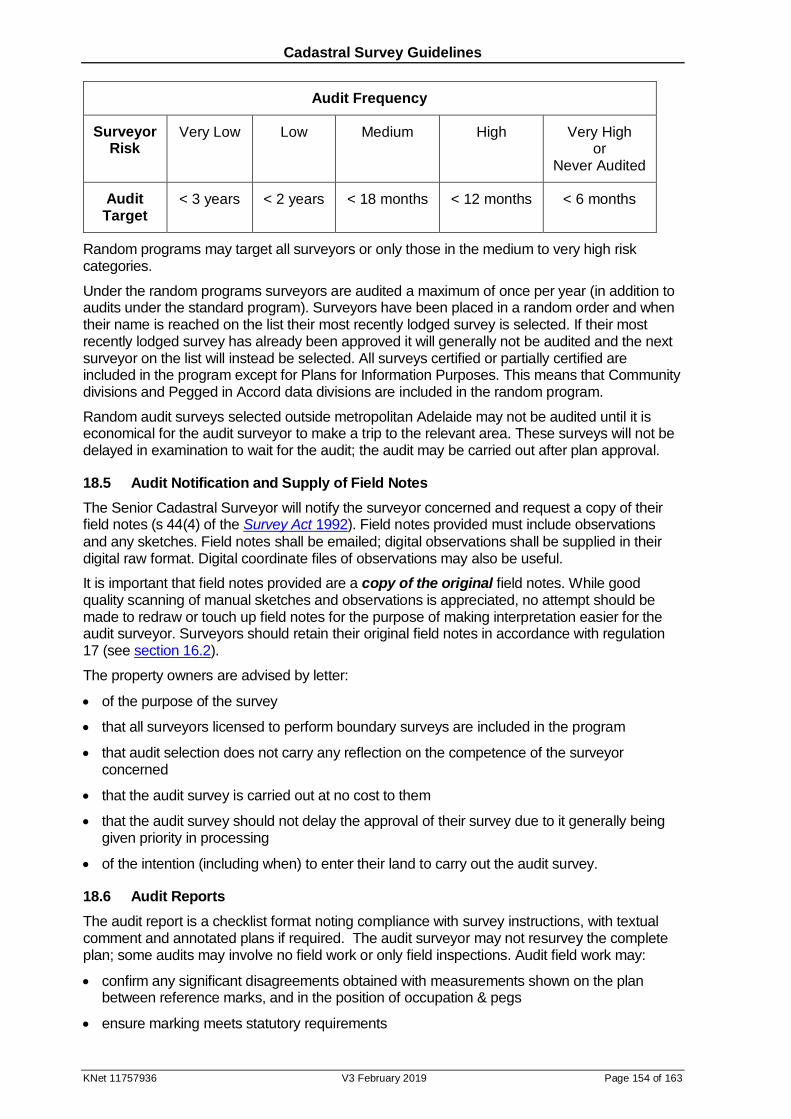
Cadastral Survey Guidelines
KNet 11757936 V3 February 2019 Page 154 of 163
Audit Frequency
Surveyor Risk
Very Low Low Medium High
Very High or
Never Audited
Audit Target
< 3 years < 2 years < 18 months < 12 months < 6 months
Random programs may target all surveyors or only those in the medium to very high risk categories.
Under the random programs surveyors are audited a maximum of once per year (in addition to audits under the standard program). Surveyors have been placed in a random order and when their name is reached on the list their most recently lodged survey is selected. If their most recently lodged survey has already been approved it will generally not be audited and the next surveyor on the list will instead be selected. All surveys certified or partially certified are included in the program except for Plans for Information Purposes. This means that Community divisions and Pegged in Accord data divisions are included in the random program.
Random audit surveys selected outside metropolitan Adelaide may not be audited until it is economical for the audit surveyor to make a trip to the relevant area. These surveys will not be delayed in examination to wait for the audit; the audit may be carried out after plan approval.
18.5 Audit Notification and Supply of Field Notes
The Senior Cadastral Surveyor will notify the surveyor concerned and request a copy of their field notes (s 44(4) of the Survey Act 1992). Field notes provided must include observations
and any sketches. Field notes shall be emailed; digital observations shall be supplied in their digital raw format. Digital coordinate files of observations may also be useful.
It is important that field notes provided are a copy of the original field notes. While good quality scanning of manual sketches and observations is appreciated, no attempt should be made to redraw or touch up field notes for the purpose of making interpretation easier for the audit surveyor. Surveyors should retain their original field notes in accordance with regulation 17 (see section 16.2).
The property owners are advised by letter:
of the purpose of the survey
that all surveyors licensed to perform boundary surveys are included in the program
that audit selection does not carry any reflection on the competence of the surveyor concerned
that the audit survey is carried out at no cost to them
that the audit survey should not delay the approval of their survey due to it generally being given priority in processing
of the intention (including when) to enter their land to carry out the audit survey.
18.6 Audit Reports
The audit report is a checklist format noting compliance with survey instructions, with textual comment and annotated plans if required. The audit surveyor may not resurvey the complete plan; some audits may involve no field work or only field inspections. Audit field work may:
confirm any significant disagreements obtained with measurements shown on the plan between reference marks, and in the position of occupation & pegs
ensure marking meets statutory requirements
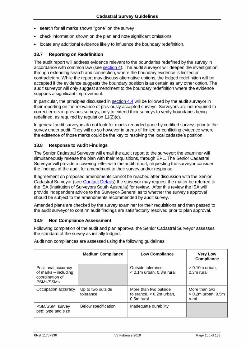
Cadastral Survey Guidelines
KNet 11757936 V3 February 2019 Page 155 of 163
search for all marks shown “gone” on the survey
check information shown on the plan and note significant omissions
locate any additional evidence likely to influence the boundary redefinition.
18.7 Reporting on Redefinition
The audit report will address evidence relevant to the boundaries redefined by the survey in accordance with common law (see section 4). The audit surveyor will deepen the investigation, through extending search and connection, where the boundary evidence is limited or contradictory. While the report may discuss alternative options, the lodged redefinition will be accepted if the evidence suggests the boundary position is as certain as any other option. The audit surveyor will only suggest amendment to the boundary redefinition where the evidence supports a significant improvement.
In particular, the principles discussed in section 4.4 will be followed by the audit surveyor in their reporting on the relevance of previously accepted surveys. Surveyors are not required to correct errors in previous surveys, only to extend their surveys to verify boundaries being redefined, as required by regulation 11(2)(c).
In general audit surveyors do not look for marks recorded gone by certified surveys prior to the survey under audit. They will do so however in areas of limited or conflicting evidence where the existence of those marks could be the key to resolving the local cadastre’s position.
18.8 Response to Audit Findings
The Senior Cadastral Surveyor will email the audit report to the surveyor; the examiner will simultaneously release the plan with their requisitions, through EPL. The Senior Cadastral Surveyor will provide a covering letter with the audit report, requesting the surveyor consider the findings of the audit for amendment to their survey and/or response.
If agreement on proposed amendments cannot be reached after discussion with the Senior Cadastral Surveyor (see Contact Details) the surveyor may request the matter be referred to the ISA (Institution of Surveyors South Australia) for review. After this review the ISA will provide independent advice to the Surveyor-General as to whether the survey’s approval should be subject to the amendments recommended by audit survey.
Amended plans are checked by the survey examiner for their requisitions and then passed to the audit surveyor to confirm audit findings are satisfactorily resolved prior to plan approval.
18.9 Non Compliance Assessment
Following completion of the audit and plan approval the Senior Cadastral Surveyor assesses the standard of the survey as initially lodged.
Audit non compliances are assessed using the following guidelines:
Medium Compliance Low Compliance Very Low Compliance
Positional accuracy of marks – including coordination of PSMs/SSMs
Outside tolerance, < 0.1m urban, 0.3m rural
> 0.10m urban, 0.3m rural
Occupation accuracy Up to two outside tolerance
More than two outside tolerance, < 0.2m urban, 0.5m rural
More than two > 0.2m urban, 0.5m rural
PSM/SSM, survey peg: type and size
Below specification
Inadequate durability
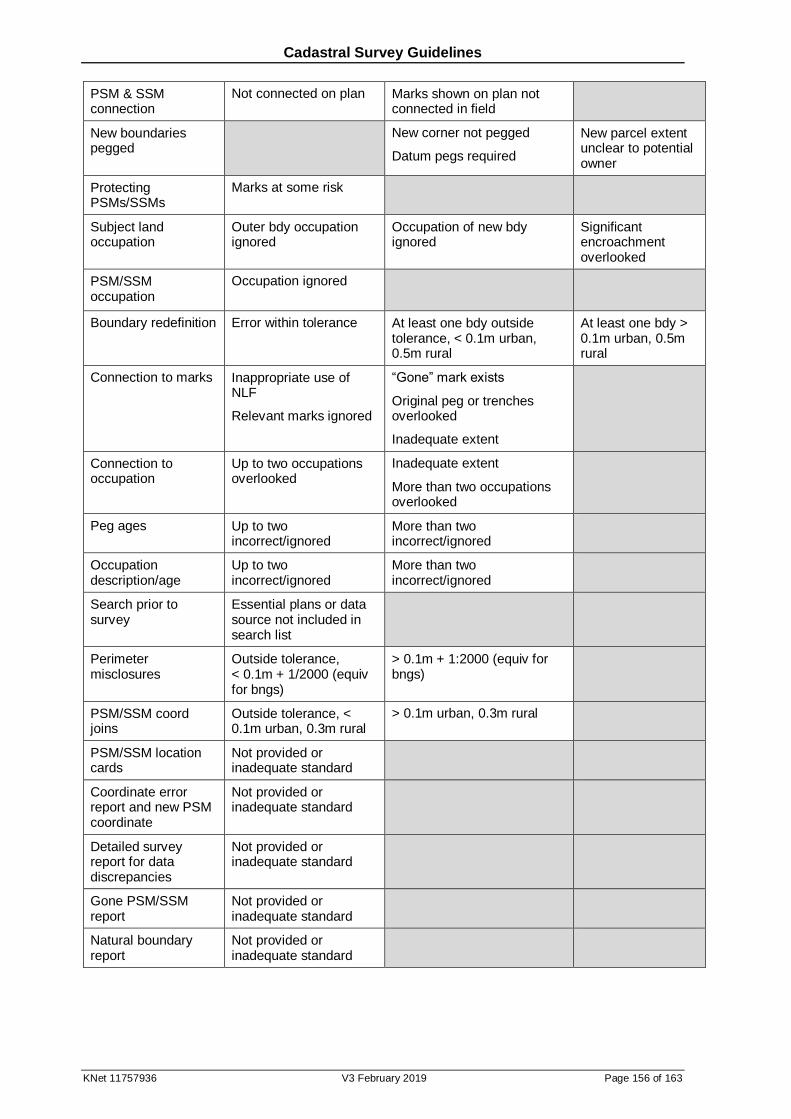
Cadastral Survey Guidelines
KNet 11757936 V3 February 2019 Page 156 of 163
PSM & SSM connection
Not connected on plan Marks shown on plan not connected in field
New boundaries pegged
New corner not pegged
Datum pegs required
New parcel extent unclear to potential owner
Protecting PSMs/SSMs
Marks at some risk
Subject land occupation
Outer bdy occupation ignored
Occupation of new bdy ignored
Significant encroachment overlooked
PSM/SSM occupation
Occupation ignored
Boundary redefinition Error within tolerance At least one bdy outside tolerance, < 0.1m urban, 0.5m rural
At least one bdy > 0.1m urban, 0.5m rural
Connection to marks Inappropriate use of NLF
Relevant marks ignored
“Gone” mark exists
Original peg or trenches overlooked
Inadequate extent
Connection to occupation
Up to two occupations overlooked
Inadequate extent
More than two occupations overlooked
Peg ages Up to two incorrect/ignored
More than two incorrect/ignored
Occupation description/age
Up to two incorrect/ignored
More than two incorrect/ignored
Search prior to survey
Essential plans or data source not included in search list
Perimeter misclosures
Outside tolerance, < 0.1m + 1/2000 (equiv for bngs)
> 0.1m + 1:2000 (equiv for bngs)
PSM/SSM coord joins
Outside tolerance, < 0.1m urban, 0.3m rural
> 0.1m urban, 0.3m rural
PSM/SSM location cards
Not provided or inadequate standard
Coordinate error report and new PSM coordinate
Not provided or inadequate standard
Detailed survey report for data discrepancies
Not provided or inadequate standard
Gone PSM/SSM report
Not provided or inadequate standard
Natural boundary report
Not provided or inadequate standard

Cadastral Survey Guidelines
KNet 11757936 V3 February 2019 Page 157 of 163
The size or complexity of the survey is not a primary factor in the above criteria however they are considered for:
‘borderline’ cases, or
medium compliances dependant on one or two occurrences of an error; greater allowance, that is more than two occurrences, will be made for larger surveys.
As well as the above tolerances and survey complexity criteria, redefinition error assessment will also consider the degree of certainty and impact on the cadastre. The low compliance for a new corner not pegged is applied if a surveyor marks a new corner with an offset mark only, despite it being practicable to place a survey peg on the corner.
These lists are not exhaustive; they only include the more common errors. Other errors of similar significance will be assessed accordingly, for example, there have been cases of occupation never measured shown on the boundary, or apparently non-existent pegs adopted. Flexibility will be applied to the above tables in mitigating circumstances.
18.10 Survey Assessment
Surveys are assessed overall on the basis of their worst non-compliance. Very low compliance errors are those considered serious enough that they shouldn’t occur no matter how large the survey. Low compliances are serious enough that only one (except occupation) disqualifies the survey from being considered high compliance. Surveys are assessed according to the following relationship:
Non Compliance/Survey Relationship
Worst Non Compliance
None Medium Compliance
Low Compliance
Very Low Compliance
Survey High Compliance Low Compliance
Very Low Compliance
Score 1 2 3
The Surveyors Board has an Audit Sub-committee, consisting of two of its members, for liaison with the Senior Cadastral Surveyor. The Senior Cadastral Surveyor will write to the surveyor advising of the survey assessment and, if a low or very low compliance survey, the date of review by the Audit Sub-committee. (High compliance audits are not reviewed.) The surveyor will be invited to respond or comment if they have any concerns about the assessments. All responses will be provided to the Audit Sub-committee.
18.11 Audit Review & Surveyor Risk Rating
The Audit Sub-committee meets with the Senior Cadastral Surveyor on a monthly basis to review low and very low compliance audits, and the audit history of the surveyor. The Sub-committee reports to the Surveyors Board as a means of ongoing monitoring of any serious issues arising from audits.
Surveyors are assigned a risk rating based on the results of their last three standard audits; their scores (see above table) being summed:
Score Total Very Low Risk
Low Risk Medium Risk
High Risk Very High Risk
Last 3 Audits 3 or 4 5 6 7 8 or 9
If only 2 Audits 2 3 4 5 6
If only 1 Audit 1 2 3
Cadastral Survey Guidelines
KNet 11757936 V3 February 2019 Page 158 of 163
A significant majority of lodged surveys are in low risk cadastres; it is anticipated that audits will show most surveys randomly selected demonstrate high compliance. Random audits will therefore not be used in the surveyor’s risk rating. However, the Surveyors Board will have discretion with this if a random audit reveals poor performance.
After confirmation or otherwise of the survey assessment by the Board the Surveyor-General will provide feedback to the surveyor with notification of their risk rating. (As high compliance audits are not reviewed the Senior Cadastral Surveyor will confirm the surveyor’s risk rating at the time of advising the survey’s assessment as high compliance.)
As well as being targeted for more frequent audits the performance of surveyors classified as high and very high risk is monitored by the Board. The Board has an intervention strategy for those surveyors who have a record of lodging very low compliance surveys and being assessed in the very high risk category. Surveyors who take real and lasting measures to implement improvement practices will be under less scrutiny.
Cadastral Survey Guidelines
KNet 11757936 V3 February 2019 Page 159 of 163
19 Miscellaneous
19.1 Trust Grants
A trust grant is a Land Grant, or its subsequent Certificate of Title, where the land has been alienated in fee simple from the Crown with a condition requiring the land to be used for a public purpose, examples being:
land granted in trust to a sporting club for clubroom purposes.
land granted in trust to the Minister of Marine for specific purposes under the Harbors Act.
land granted in trust to a district hospital as a Hospital Reserve.
In some cases the issue of a trust grant serves an additional purpose of providing a document for use as security for raising finance by way of a registered mortgage.
Land held in the form of a trust grant may be identified by wording on the Title such as:
In trust to permit and suffer the said piece of land to be used at all times...
There are a variety of statutes under which a trust grant may have been issued, for example, the Crown Lands Act, and the Libraries and Institutes Act; each Act may have its own particular requirements and therefore dealings with trust grants may be a complex process.
Trusts subsist and affect land until such times as they are resumed or are freed from trust by proclamation of the Governor in the Gazette. Such resumption or freeing from trust requires the approval of the Minister.
Where land in a plan of division is subject to a trust it must first be determined whether the trust is to be carried forward or is to be withdrawn. Divisions of trust grants can not be deposited without gazettal of the withdrawal over the appropriate land. It should be noted that some trust grants have erroneously been carried forward on Titles when in fact they have been withdrawn.
Because of the complexities, full details of a proposal involving trust land should be forwarded to the Crown Tenure Unit of the Department of Environment, Water & Natural Resources (DEWNR) prior to any commitments being entered into. This contact is necessary to determine appropriate approvals and the correct procedure necessary to implement the transaction.
19.2 Public Map
The Public Map has formed a record of the location, shape, size and description of all land parcels of the Crown and ‘Government’ roads for more than 150 years. Updating of the Public Map ceased in 1987.
The Public Map is the legal authority for the creation of some public roads, 150 link reserves, and for the enhancement of the description of land contained in Crown tenures such as leases and Land Grants. Amendments to legislation negated the need for the Public Map to continue as a dynamic record:
Section 301 (1) of the Local Government Act 1934 was amended so that transfer or
surrender of land to the Crown for road purposes, when endorsed on the Certificate of Title or Crown Lease, became the authority for the creation of these public roads.
In the case of a road created in a survey of Crown Land the authority is its dedication by a notice in the Government Gazette pursuant to s.5 (d) II of the Crown Lands Act 1929.
Amendments to the Irrigation Act 1930 and Crown Lands Act 1929 enabled leases and Land
Grants to refer to the relevant survey diagram rather than the Public Map.
The Property Location Browser (see section 9.3a) provides a dynamic index to land tenure information provided by the Public Map, as well as freehold land. Although the Public Map is a static record it remains as the legal protection for any action dependant on it, including roads already delineated. It is available for searching (see section 9.3b).
Cadastral Survey Guidelines
KNet 11757936 V3 February 2019 Page 160 of 163
19.3 Limited Examination of Diagram Book Pages
The purpose of this subsection is to provide Licensed Surveyors with details relating to the period when the method of survey examination in the office of the Surveyor-General was relaxed.
During the period of approximately February 1971 to April 1974 survey diagrams were accepted for deposit endorsed with the following note:
IMPORTANT
The data and boundary definition as disclosed on this plan have not been examined by the Surveyor-General.
These survey diagrams were generally examined for plan presentation only, and authorised accordingly in the appropriate space in the legend of the diagram.
Surveys conducted by surveyors employed by the Department of Lands during the period were authorised for both plan and boundaries; the above note was not used on these diagram pages. However, the examination was not done by the customary data comparison method.
Surveyors should be aware that there could have been inconsistencies in notation during the period of this procedure. The significance of this issue is that the level of examination was less than that prior to February 1971 and subsequent to April 1974.
In spite of any variation to survey examination practice, it is the responsibility of all surveyors to define boundaries according to approved cadastral boundary principles.
19.4 Surveys for Aquaculture Leases
Land underlying marine waters within the jurisdiction of the State is vested in fee simple to the Minister for Transport & Infrastructure pursuant to the Harbors and Navigation Act 1993. Aquaculture leases issued over such lands are to be registered under the Real Property Act by issuing Certificates of Title to the Minister for Transport over parcels of the seabed which have been the subject of successful aquaculture applications. By way of delegated authority from the Minister for Transport & Infrastructure, the Minister for Agriculture, Food & Fisheries will then issue leases over these Titles.
Throughout South Australia the relevant planning authority regarding marine aquaculture development is the Aquaculture Committee of the Development Assessment Commission (DAC). The only exception to this is the District Council of Franklin Harbor where the council is the relevant authority. The DAC is supported in its role by the Aquaculture Group of PIRSA (Department of Primary Industries & Regions SA).
Land division for the purpose of aquaculture necessitates some changes to normal land division procedures; these are highlighted below. In particular, it should be noted that some aquaculture sites have already been given planning approval on the basis of applications that were not vouched for by a licensed surveyor. As such, certified survey may reveal problems with the location of the approved site. Special criteria have been developed for these sites (see d. below).
a. Proposal Plan
In order for aquaculture applications to be assessed by the DAC it is necessary for the application to be accompanied by a proposal plan of the intended site. This plan must be prepared and vouched for by a licensed surveyor. Where such a plan is not submitted at the time of initial lodgement of the application with the DAC, applicants will be sent a letter requesting a proposal plan as described below.
During preparation of the proposal plan surveyors should assist applicants identify and mark the preferred site with buoys, mindful of the aquaculture siting guidelines and policies adopted by DAC, the relevant Aquaculture Management Plan, and any other relevant information provided by the Aquaculture Group. Surveyors are encouraged to contact the Aquaculture

Cadastral Survey Guidelines
KNet 11757936 V3 February 2019 Page 161 of 163
Group before undertaking a proposal plan. The Aquaculture Group can provide information about adjoining sites or applications, and other relevant local conditions.
Based on appropriate site measurements surveyors shall produce a proposal plan of division showing:
the dimensions of the site,
the area of the site in hectares,
approximate MGA2020 coordinates for the corners of the proposed site, scaled from the largest scale topographic map available,
measured distances between the most landward point of the site and any prominent adjacent features,
adjacent MHWM (derived graphically), and
allotment numbers.
In remote areas a smaller scale “site plan” must be included in the plan so as to assist in identifying the relevant area of the coast.
All sheets in the proposal plan must include the following certificate:
Vouched for
............................................................
Licensed Surveyor / /
Where the proposal plan is not lodged with the initial application it should be submitted direct to the Aquaculture Group for assessment by the DAC.
b. Certified Survey
Upon approval of the application by DAC applicants will be required to engage a licensed surveyor to complete a certified survey of the site. A certified survey will be necessary for the issuing of an Aquaculture lease.
1. Normal PSM and reference mark spacing requirements do not apply, however PSMs connected or placed must be adequate to control the survey (three local PSMs is considered the minimum to facilitate future surveys).
2. Surveys in areas where geodetic control is available (PSMs or other marks with PU 0.1m or better MGA2020 coordinates) must connect to that control. One of the local PSMs required in 1. above may be dispensed with if the geodetic control connected on the plan includes a beaconed trig visible from the coastline adjacent to the aquaculture site.
3. Normal requirements for PSMs placed or connected to, such as siting, construction, protection and witnessing, location sketches, occupation, and numbering, shall apply.
4. For intertidal sites, new corners are to be marked with star droppers driven full length into the seabed. Normal rural cadastral accuracy requirements shall apply.
5. For deep water sites new corners are to be marked with heavy objects placed on the sea bed (for example a concrete block). These should be large enough to remain in place under the influence of tides and storms. Due to the difficulty of accurately placing these marks, it is recognised that normal accuracy tolerances are inappropriate. However it is expected that horizontal marking will be within a positional tolerance defined as equal to the depth of the water.
6. Surveyors should ensure that the position of new parcels is in accord with the plotted position in the approved proposal plan. Where this conflicts with the approximate coordinates specified in the proposal plan, the plotted position shall prevail.
Cadastral Survey Guidelines
KNet 11757936 V3 February 2019 Page 162 of 163
c. Certified Survey Plan
1. The parcels will be created by Plan of Division and Application Under Section 115a of the Real Property Act (plan heading shown in italics). The plan must be prepared as a DP,
however there is no need to show the balance parcel.
2. Many aquaculture sites are in areas remote from readily identifiable cadastral corners and abuttals. In these instances a smaller scale “site plan” must be included in the plan so as to assist in identifying the relevant area of the coast. For the same reason, the plan must also provide connections from the PSMs to physical features, with notes on the witnessing provided for the PSMs.
3. Plans must show bearings and distances for all parcel boundaries.
4. Plans must show MGA2020 coordinates for all parcel corners and PSMs (and other geodetic control) connected, in a schedule.
5. Where geodetic control (MGA2020 coordinates with PU better than 0.1m) has not been connected an origin coordinate is to be scaled from the largest scale map available for the area. This should be highlighted by way of a note alongside the appropriate line of the coordinate schedule:
Origin coordinate scaled from map 6627-IV
6. Distant geodetic control (such as trig points) connected on the survey need not be plotted.
7. It is not necessary to show bearings and distances between PSMs, or from PSMs to parcel corners.
8. The plan must describe the parcel corner marking.
9. Prior to lodgement with the LTO three copies of the plan must be sent by the lodging party to:
Project Officer (Leasing/Licensing) Aquaculture Group PIRSA PO Box 1625 ADELAIDE 5001
The Aquaculture Group will return a copy of the plan to the surveyor with a stamp indicating their approval of the surveyed site, as a pre requisite for LTO plan approval. This stamped copy of the plan should be forwarded to the LTO together with the original.
d. Survey of Approved Sites with No Proposal Plan
In cases where applications have been approved on the basis of MGA2020 coordinates, not a proposal plan (as described in a) above), certified surveys should describe the site with MGA2020 coordinates that, as far as possible, match the coordinates approved by DAC (or DC Franklin Harbor). It is acknowledged, however, that under some circumstances this may be difficult or impossible.
Where coordinates of surveyed lease boundaries must of necessity be different from those approved, a new application to move the site to that location must be made. Note that where the move is considered of a minor nature there are provisions within the Development Act to exempt such applications from the public notification process, thereby streamlining the assessment process. The relevant planning authority is responsible for determining the cases in which this provision may be employed.
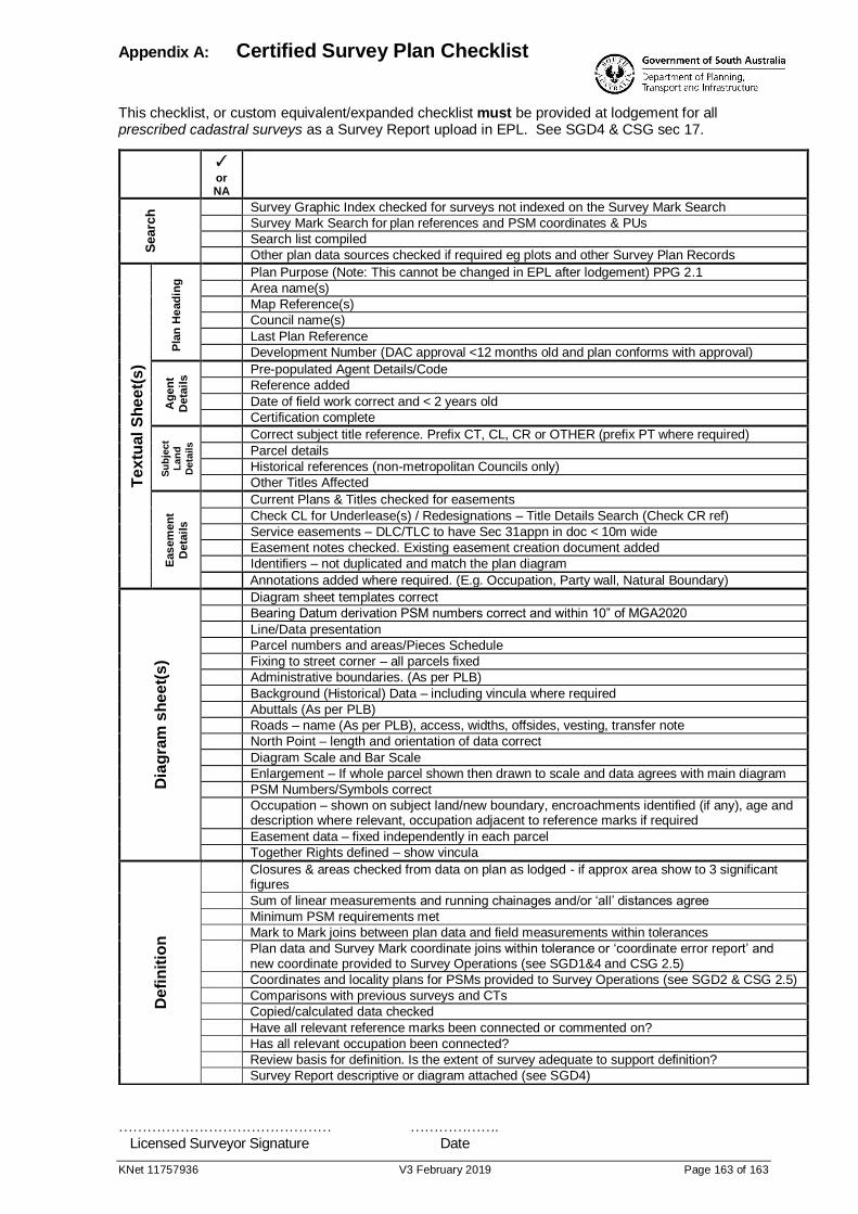
Appendix A: Certified Survey Plan Checklist
KNet 11757936 V3 February 2019 Page 163 of 163
This checklist, or custom equivalent/expanded checklist must be provided at lodgement for all prescribed cadastral surveys as a Survey Report upload in EPL. See SGD4 & CSG sec 17.
……………………………………… ……………….
Licensed Surveyor Signature Date
✓or NA
S
earc
h Survey Graphic Index checked for surveys not indexed on the Survey Mark Search
Survey Mark Search for plan references and PSM coordinates & PUs
Search list compiled
Other plan data sources checked if required eg plots and other Survey Plan Records
Te
xtu
al
Sh
ee
t(s
)
Pla
n H
ead
ing
Plan Purpose (Note: This cannot be changed in EPL after lodgement) PPG 2.1
Area name(s)
Map Reference(s)
Council name(s)
Last Plan Reference
Development Number (DAC approval <12 months old and plan conforms with approval)
Ag
en
t
Deta
ils
Pre-populated Agent Details/Code
Reference added
Date of field work correct and < 2 years old
Certification complete
Su
bje
ct
Lan
d
Deta
ils
Correct subject title reference. Prefix CT, CL, CR or OTHER (prefix PT where required)
Parcel details
Historical references (non-metropolitan Councils only)
Other Titles Affected
Eas
em
en
t
Deta
ils
Current Plans & Titles checked for easements
Check CL for Underlease(s) / Redesignations – Title Details Search (Check CR ref)
Service easements – DLC/TLC to have Sec 31appn in doc < 10m wide
Easement notes checked. Existing easement creation document added
Identifiers – not duplicated and match the plan diagram
Annotations added where required. (E.g. Occupation, Party wall, Natural Boundary)
Dia
gra
m s
he
et(
s)
Diagram sheet templates correct
Bearing Datum derivation PSM numbers correct and within 10” of MGA2020
Line/Data presentation
Parcel numbers and areas/Pieces Schedule
Fixing to street corner – all parcels fixed
Administrative boundaries. (As per PLB)
Background (Historical) Data – including vincula where required
Abuttals (As per PLB)
Roads – name (As per PLB), access, widths, offsides, vesting, transfer note
North Point – length and orientation of data correct
Diagram Scale and Bar Scale
Enlargement – If whole parcel shown then drawn to scale and data agrees with main diagram
PSM Numbers/Symbols correct
Occupation – shown on subject land/new boundary, encroachments identified (if any), age and description where relevant, occupation adjacent to reference marks if required
Easement data – fixed independently in each parcel
Together Rights defined – show vincula
De
fin
itio
n
Closures & areas checked from data on plan as lodged - if approx area show to 3 significant figures
Sum of linear measurements and running chainages and/or ‘all’ distances agree
Minimum PSM requirements met
Mark to Mark joins between plan data and field measurements within tolerances
Plan data and Survey Mark coordinate joins within tolerance or ‘coordinate error report’ and new coordinate provided to Survey Operations (see SGD1&4 and CSG 2.5)
Coordinates and locality plans for PSMs provided to Survey Operations (see SGD2 & CSG 2.5)
Comparisons with previous surveys and CTs
Copied/calculated data checked
Have all relevant reference marks been connected or commented on?
Has all relevant occupation been connected?
Review basis for definition. Is the extent of survey adequate to support definition?
Survey Report descriptive or diagram attached (see SGD4)