cadence verilog -ams language referencebibyk/ece822/verilogamsref.pdf · cadence verilog-ams...
TRANSCRIPT

Cadence® Verilog®-AMS LanguageReference
Product Version 5.5June 2005

2000-2005 Cadence Design Systems, Inc. All rights reserved.Printed in the United States of America.
Cadence Design Systems, Inc., 555 River Oaks Parkway, San Jose, CA 95134, USA
Trademarks: Trademarks and service marks of Cadence Design Systems, Inc. (Cadence) contained inthis document are attributed to Cadence with the appropriate symbol. For queries regarding Cadence’strademarks, contact the corporate legal department at the address shown above or call 800.862.4522.
Open SystemC, Open SystemC Initiative, OSCI, SystemC, and SystemC Initiative are trademarks orregistered trademarks of Open SystemC Initiative, Inc. in the United States and other countries and areused with permission.
All other trademarks are the property of their respective holders.
Restricted Print Permission: This publication is protected by copyright and any unauthorized use of thispublication may violate copyright, trademark, and other laws. Except as specified in this permissionstatement, this publication may not be copied, reproduced, modified, published, uploaded, posted,transmitted, or distributed in any way, without prior written permission from Cadence. This statement grantsyou permission to print one (1) hard copy of this publication subject to the following conditions:
1. The publication may be used solely for personal, informational, and noncommercial purposes;2. The publication may not be modified in any way;3. Any copy of the publication or portion thereof must include all original copyright, trademark, and other
proprietary notices and this permission statement; and4. Cadence reserves the right to revoke this authorization at any time, and any such use shall be
discontinued immediately upon written notice from Cadence.
Disclaimer: Information in this publication is subject to change without notice and does not represent acommitment on the part of Cadence. The information contained herein is the proprietary and confidentialinformation of Cadence or its licensors, and is supplied subject to, and may be used only by Cadence’scustomer in accordance with, a written agreement between Cadence and its customer. Except as may beexplicitly set forth in such agreement, Cadence does not make, and expressly disclaims, anyrepresentations or warranties as to the completeness, accuracy or usefulness of the information containedin this document. Cadence does not warrant that use of such information will not infringe any third partyrights, nor does Cadence assume any liability for damages or costs of any kind that may result from use ofsuch information.
Restricted Rights: Use, duplication, or disclosure by the Government is subject to restrictions as set forthin FAR52.227-14 and DFAR252.227-7013 et seq. or its successor.

Cadence Verilog-AMS Language Reference
Contents
Preface . . . . . . . . . . . . . . . . . . . . . . . . . . . . . . . . . . . . . . . . . . . . . . . . . . . . . . . . . . . . . 17
Related Documents . . . . . . . . . . . . . . . . . . . . . . . . . . . . . . . . . . . . . . . . . . . . . . . . . . . . . 18Internet Mail Address . . . . . . . . . . . . . . . . . . . . . . . . . . . . . . . . . . . . . . . . . . . . . . . . . . . . 19Typographic and Syntax Conventions . . . . . . . . . . . . . . . . . . . . . . . . . . . . . . . . . . . . . . . 19
1Modeling Concepts . . . . . . . . . . . . . . . . . . . . . . . . . . . . . . . . . . . . . . . . . . . . . . . 21
Verilog-A Language Overview . . . . . . . . . . . . . . . . . . . . . . . . . . . . . . . . . . . . . . . . . . . . . 22Describing a System . . . . . . . . . . . . . . . . . . . . . . . . . . . . . . . . . . . . . . . . . . . . . . . . . . . . 22Analog Systems . . . . . . . . . . . . . . . . . . . . . . . . . . . . . . . . . . . . . . . . . . . . . . . . . . . . . . . . 23
Nodes . . . . . . . . . . . . . . . . . . . . . . . . . . . . . . . . . . . . . . . . . . . . . . . . . . . . . . . . . . . . . 23Conservative Systems . . . . . . . . . . . . . . . . . . . . . . . . . . . . . . . . . . . . . . . . . . . . . . . . 24Signal-Flow Systems . . . . . . . . . . . . . . . . . . . . . . . . . . . . . . . . . . . . . . . . . . . . . . . . . 24Mixed Conservative and Signal-Flow Systems . . . . . . . . . . . . . . . . . . . . . . . . . . . . . 25Simulator Flow for Analog Systems . . . . . . . . . . . . . . . . . . . . . . . . . . . . . . . . . . . . . . 25
2Creating Modules . . . . . . . . . . . . . . . . . . . . . . . . . . . . . . . . . . . . . . . . . . . . . . . . . 27
Overview . . . . . . . . . . . . . . . . . . . . . . . . . . . . . . . . . . . . . . . . . . . . . . . . . . . . . . . . . . . . . 28Declaring Modules . . . . . . . . . . . . . . . . . . . . . . . . . . . . . . . . . . . . . . . . . . . . . . . . . . . . . . 28Declaring the Module Interface . . . . . . . . . . . . . . . . . . . . . . . . . . . . . . . . . . . . . . . . . . . . 31
Module Name . . . . . . . . . . . . . . . . . . . . . . . . . . . . . . . . . . . . . . . . . . . . . . . . . . . . . . . 31Ports . . . . . . . . . . . . . . . . . . . . . . . . . . . . . . . . . . . . . . . . . . . . . . . . . . . . . . . . . . . . . . 31Parameters . . . . . . . . . . . . . . . . . . . . . . . . . . . . . . . . . . . . . . . . . . . . . . . . . . . . . . . . . 34
Defining Module Analog Behavior . . . . . . . . . . . . . . . . . . . . . . . . . . . . . . . . . . . . . . . . . . 34Defining Analog Behavior with Control Flow . . . . . . . . . . . . . . . . . . . . . . . . . . . . . . . 36Using Integration and Differentiation with Analog Signals . . . . . . . . . . . . . . . . . . . . . 38
Using Internal Nodes in Modules . . . . . . . . . . . . . . . . . . . . . . . . . . . . . . . . . . . . . . . . . . . 39Using Internal Nodes in Behavioral Definitions . . . . . . . . . . . . . . . . . . . . . . . . . . . . . 39Using Internal Nodes in Higher Order Systems . . . . . . . . . . . . . . . . . . . . . . . . . . . . . 40
June 2005 3 Product Version 5.5

Cadence Verilog-AMS Language Reference
3Lexical Conventions . . . . . . . . . . . . . . . . . . . . . . . . . . . . . . . . . . . . . . . . . . . . . . 43
White Space . . . . . . . . . . . . . . . . . . . . . . . . . . . . . . . . . . . . . . . . . . . . . . . . . . . . . . . . . . 44Comments . . . . . . . . . . . . . . . . . . . . . . . . . . . . . . . . . . . . . . . . . . . . . . . . . . . . . . . . . . . . 44Identifiers . . . . . . . . . . . . . . . . . . . . . . . . . . . . . . . . . . . . . . . . . . . . . . . . . . . . . . . . . . . . . 44
Ordinary Identifiers . . . . . . . . . . . . . . . . . . . . . . . . . . . . . . . . . . . . . . . . . . . . . . . . . . . 45Escaped Names . . . . . . . . . . . . . . . . . . . . . . . . . . . . . . . . . . . . . . . . . . . . . . . . . . . . . 45Scope Rules . . . . . . . . . . . . . . . . . . . . . . . . . . . . . . . . . . . . . . . . . . . . . . . . . . . . . . . . 45
Numbers . . . . . . . . . . . . . . . . . . . . . . . . . . . . . . . . . . . . . . . . . . . . . . . . . . . . . . . . . . . . . 46Integer Numbers . . . . . . . . . . . . . . . . . . . . . . . . . . . . . . . . . . . . . . . . . . . . . . . . . . . . . 46Real Numbers . . . . . . . . . . . . . . . . . . . . . . . . . . . . . . . . . . . . . . . . . . . . . . . . . . . . . . 46
Strings . . . . . . . . . . . . . . . . . . . . . . . . . . . . . . . . . . . . . . . . . . . . . . . . . . . . . . . . . . . . . . . 47
4Data Types and Objects . . . . . . . . . . . . . . . . . . . . . . . . . . . . . . . . . . . . . . . . . 49
Integer Numbers . . . . . . . . . . . . . . . . . . . . . . . . . . . . . . . . . . . . . . . . . . . . . . . . . . . . . . . 50Real Numbers . . . . . . . . . . . . . . . . . . . . . . . . . . . . . . . . . . . . . . . . . . . . . . . . . . . . . . . . . 50
Converting Real Numbers to Integer Numbers . . . . . . . . . . . . . . . . . . . . . . . . . . . . . 51Parameters . . . . . . . . . . . . . . . . . . . . . . . . . . . . . . . . . . . . . . . . . . . . . . . . . . . . . . . . . . . 51
Specifying a Parameter Type . . . . . . . . . . . . . . . . . . . . . . . . . . . . . . . . . . . . . . . . . . . 52Specifying Permissible Values . . . . . . . . . . . . . . . . . . . . . . . . . . . . . . . . . . . . . . . . . . 53
Natures . . . . . . . . . . . . . . . . . . . . . . . . . . . . . . . . . . . . . . . . . . . . . . . . . . . . . . . . . . . . . . 54Declaring a Base Nature . . . . . . . . . . . . . . . . . . . . . . . . . . . . . . . . . . . . . . . . . . . . . . 55
Disciplines . . . . . . . . . . . . . . . . . . . . . . . . . . . . . . . . . . . . . . . . . . . . . . . . . . . . . . . . . . . . 57Binding Natures with Potential and Flow . . . . . . . . . . . . . . . . . . . . . . . . . . . . . . . . . . 58Binding Domains with Disciplines . . . . . . . . . . . . . . . . . . . . . . . . . . . . . . . . . . . . . . . . 59Disciplines and Domains of Wires and Undeclared Nets . . . . . . . . . . . . . . . . . . . . . . 60Discipline Precedence . . . . . . . . . . . . . . . . . . . . . . . . . . . . . . . . . . . . . . . . . . . . . . . . 60Compatibility of Disciplines . . . . . . . . . . . . . . . . . . . . . . . . . . . . . . . . . . . . . . . . . . . . . 60
Net Disciplines . . . . . . . . . . . . . . . . . . . . . . . . . . . . . . . . . . . . . . . . . . . . . . . . . . . . . . . . . 63Ground Nodes . . . . . . . . . . . . . . . . . . . . . . . . . . . . . . . . . . . . . . . . . . . . . . . . . . . . . . . . . 65Real Nets . . . . . . . . . . . . . . . . . . . . . . . . . . . . . . . . . . . . . . . . . . . . . . . . . . . . . . . . . . . . . 65Named Branches . . . . . . . . . . . . . . . . . . . . . . . . . . . . . . . . . . . . . . . . . . . . . . . . . . . . . . . 66Implicit Branches . . . . . . . . . . . . . . . . . . . . . . . . . . . . . . . . . . . . . . . . . . . . . . . . . . . . . . . 67
June 2005 4 Product Version 5.5

Cadence Verilog-AMS Language Reference
5Statements for the Analog Block. . . . . . . . . . . . . . . . . . . . . . . . . . . . . . . . 69
Assignment Statements . . . . . . . . . . . . . . . . . . . . . . . . . . . . . . . . . . . . . . . . . . . . . . . . . . 69Procedural Assignment Statements in the Analog Block . . . . . . . . . . . . . . . . . . . . . . 70Branch Contribution Statement . . . . . . . . . . . . . . . . . . . . . . . . . . . . . . . . . . . . . . . . . 70Indirect Branch Assignment Statement . . . . . . . . . . . . . . . . . . . . . . . . . . . . . . . . . . . 72
Sequential Block Statement . . . . . . . . . . . . . . . . . . . . . . . . . . . . . . . . . . . . . . . . . . . . . . . 73Conditional Statement . . . . . . . . . . . . . . . . . . . . . . . . . . . . . . . . . . . . . . . . . . . . . . . . . . . 74Case Statement . . . . . . . . . . . . . . . . . . . . . . . . . . . . . . . . . . . . . . . . . . . . . . . . . . . . . . . . 74Repeat Statement . . . . . . . . . . . . . . . . . . . . . . . . . . . . . . . . . . . . . . . . . . . . . . . . . . . . . . 75While Statement . . . . . . . . . . . . . . . . . . . . . . . . . . . . . . . . . . . . . . . . . . . . . . . . . . . . . . . 76For Statement . . . . . . . . . . . . . . . . . . . . . . . . . . . . . . . . . . . . . . . . . . . . . . . . . . . . . . . . . 76Generate Statement . . . . . . . . . . . . . . . . . . . . . . . . . . . . . . . . . . . . . . . . . . . . . . . . . . . . 77
6Operators for Analog Blocks . . . . . . . . . . . . . . . . . . . . . . . . . . . . . . . . . . . . 81
Overview of Operators . . . . . . . . . . . . . . . . . . . . . . . . . . . . . . . . . . . . . . . . . . . . . . . . . . . 82Unary Operators . . . . . . . . . . . . . . . . . . . . . . . . . . . . . . . . . . . . . . . . . . . . . . . . . . . . . . . 83
Unary Reduction Operators . . . . . . . . . . . . . . . . . . . . . . . . . . . . . . . . . . . . . . . . . . . . 83Binary Operators . . . . . . . . . . . . . . . . . . . . . . . . . . . . . . . . . . . . . . . . . . . . . . . . . . . . . . . 85
Bitwise Operators . . . . . . . . . . . . . . . . . . . . . . . . . . . . . . . . . . . . . . . . . . . . . . . . . . . . 88Ternary Operator . . . . . . . . . . . . . . . . . . . . . . . . . . . . . . . . . . . . . . . . . . . . . . . . . . . . . . . 89Operator Precedence . . . . . . . . . . . . . . . . . . . . . . . . . . . . . . . . . . . . . . . . . . . . . . . . . . . 90Expression Short-Circuiting . . . . . . . . . . . . . . . . . . . . . . . . . . . . . . . . . . . . . . . . . . . . . . . 90
7Built-In Mathematical Functions . . . . . . . . . . . . . . . . . . . . . . . . . . . . . . . . 91
Standard Mathematical Functions . . . . . . . . . . . . . . . . . . . . . . . . . . . . . . . . . . . . . . . . . . 92Trigonometric and Hyperbolic Functions . . . . . . . . . . . . . . . . . . . . . . . . . . . . . . . . . . . . . 92Controlling How Math Domain Errors Are Handled . . . . . . . . . . . . . . . . . . . . . . . . . . . . . 93
June 2005 5 Product Version 5.5

Cadence Verilog-AMS Language Reference
8Detecting and Using Events . . . . . . . . . . . . . . . . . . . . . . . . . . . . . . . . . . . . . 95
Detecting and Using Events . . . . . . . . . . . . . . . . . . . . . . . . . . . . . . . . . . . . . . . . . . . . . . . 96Initial_step Event . . . . . . . . . . . . . . . . . . . . . . . . . . . . . . . . . . . . . . . . . . . . . . . . . . . . 97Final_step Event . . . . . . . . . . . . . . . . . . . . . . . . . . . . . . . . . . . . . . . . . . . . . . . . . . . . . 98Cross Event . . . . . . . . . . . . . . . . . . . . . . . . . . . . . . . . . . . . . . . . . . . . . . . . . . . . . . . . 99Above Event . . . . . . . . . . . . . . . . . . . . . . . . . . . . . . . . . . . . . . . . . . . . . . . . . . . . . . . 100Timer Event . . . . . . . . . . . . . . . . . . . . . . . . . . . . . . . . . . . . . . . . . . . . . . . . . . . . . . . 102
9Simulator Functions . . . . . . . . . . . . . . . . . . . . . . . . . . . . . . . . . . . . . . . . . . . . . 103
Announcing Discontinuity . . . . . . . . . . . . . . . . . . . . . . . . . . . . . . . . . . . . . . . . . . . . . . . 105Bounding the Time Step . . . . . . . . . . . . . . . . . . . . . . . . . . . . . . . . . . . . . . . . . . . . . . . . 107Finding When a Signal Is Zero . . . . . . . . . . . . . . . . . . . . . . . . . . . . . . . . . . . . . . . . . . . 107Querying the Simulation Environment . . . . . . . . . . . . . . . . . . . . . . . . . . . . . . . . . . . . . . 108
Obtaining the Current Simulation Time . . . . . . . . . . . . . . . . . . . . . . . . . . . . . . . . . . 109Obtaining the Current Ambient Temperature . . . . . . . . . . . . . . . . . . . . . . . . . . . . . . 109Obtaining the Thermal Voltage . . . . . . . . . . . . . . . . . . . . . . . . . . . . . . . . . . . . . . . . . 110
Obtaining and Setting Signal Values . . . . . . . . . . . . . . . . . . . . . . . . . . . . . . . . . . . . . . . 110Obtaining Currents Using Out-of-Module References . . . . . . . . . . . . . . . . . . . . . . . 112
Accessing Attributes . . . . . . . . . . . . . . . . . . . . . . . . . . . . . . . . . . . . . . . . . . . . . . . . . . . 113Examining Drivers . . . . . . . . . . . . . . . . . . . . . . . . . . . . . . . . . . . . . . . . . . . . . . . . . . . . . 114
Counting the Number of Drivers . . . . . . . . . . . . . . . . . . . . . . . . . . . . . . . . . . . . . . . . 114Determining the Value Contribution of a Driver . . . . . . . . . . . . . . . . . . . . . . . . . . . . 115Determining the Strength of a Driver . . . . . . . . . . . . . . . . . . . . . . . . . . . . . . . . . . . . 115Detecting Updates to Drivers . . . . . . . . . . . . . . . . . . . . . . . . . . . . . . . . . . . . . . . . . . 116
Analysis-Dependent Functions . . . . . . . . . . . . . . . . . . . . . . . . . . . . . . . . . . . . . . . . . . . 116Determining the Current Analysis Type . . . . . . . . . . . . . . . . . . . . . . . . . . . . . . . . . . 116Implementing Small-Signal AC Sources . . . . . . . . . . . . . . . . . . . . . . . . . . . . . . . . . . 118Implementing Small-Signal Noise Sources . . . . . . . . . . . . . . . . . . . . . . . . . . . . . . . 118
Generating Random Numbers . . . . . . . . . . . . . . . . . . . . . . . . . . . . . . . . . . . . . . . . . . . . 120Generating Random Numbers in Specified Distributions . . . . . . . . . . . . . . . . . . . . . . . . 121
Uniform Distribution . . . . . . . . . . . . . . . . . . . . . . . . . . . . . . . . . . . . . . . . . . . . . . . . . 121Normal (Gaussian) Distribution . . . . . . . . . . . . . . . . . . . . . . . . . . . . . . . . . . . . . . . . 122
June 2005 6 Product Version 5.5

Cadence Verilog-AMS Language Reference
Exponential Distribution . . . . . . . . . . . . . . . . . . . . . . . . . . . . . . . . . . . . . . . . . . . . . . 123Poisson Distribution . . . . . . . . . . . . . . . . . . . . . . . . . . . . . . . . . . . . . . . . . . . . . . . . . 123Chi-Square Distribution . . . . . . . . . . . . . . . . . . . . . . . . . . . . . . . . . . . . . . . . . . . . . . 124Student’s T Distribution . . . . . . . . . . . . . . . . . . . . . . . . . . . . . . . . . . . . . . . . . . . . . . 125Erlang Distribution . . . . . . . . . . . . . . . . . . . . . . . . . . . . . . . . . . . . . . . . . . . . . . . . . . 126
Determining Whether a Parameter Value is Overridden . . . . . . . . . . . . . . . . . . . . . . . . 126Interpolating with Table Models . . . . . . . . . . . . . . . . . . . . . . . . . . . . . . . . . . . . . . . . . . . 127
Table Model File Format . . . . . . . . . . . . . . . . . . . . . . . . . . . . . . . . . . . . . . . . . . . . . . 128Example . . . . . . . . . . . . . . . . . . . . . . . . . . . . . . . . . . . . . . . . . . . . . . . . . . . . . . . . . . 130
Analog Operators . . . . . . . . . . . . . . . . . . . . . . . . . . . . . . . . . . . . . . . . . . . . . . . . . . . . . . 130Restrictions on Using Analog Operators . . . . . . . . . . . . . . . . . . . . . . . . . . . . . . . . . 131Limited Exponential Function . . . . . . . . . . . . . . . . . . . . . . . . . . . . . . . . . . . . . . . . . . 131Time Derivative Operator . . . . . . . . . . . . . . . . . . . . . . . . . . . . . . . . . . . . . . . . . . . . . 131Time Integral Operator . . . . . . . . . . . . . . . . . . . . . . . . . . . . . . . . . . . . . . . . . . . . . . . 132Circular Integrator Operator . . . . . . . . . . . . . . . . . . . . . . . . . . . . . . . . . . . . . . . . . . . 133Delay Operator . . . . . . . . . . . . . . . . . . . . . . . . . . . . . . . . . . . . . . . . . . . . . . . . . . . . . 135Transition Filter . . . . . . . . . . . . . . . . . . . . . . . . . . . . . . . . . . . . . . . . . . . . . . . . . . . . . 136Slew Filter . . . . . . . . . . . . . . . . . . . . . . . . . . . . . . . . . . . . . . . . . . . . . . . . . . . . . . . . . 140Implementing Laplace Transform S-Domain Filters . . . . . . . . . . . . . . . . . . . . . . . . . 141Implementing Z-Transform Filters . . . . . . . . . . . . . . . . . . . . . . . . . . . . . . . . . . . . . . . 147
Displaying Results . . . . . . . . . . . . . . . . . . . . . . . . . . . . . . . . . . . . . . . . . . . . . . . . . . . . . 151$strobe . . . . . . . . . . . . . . . . . . . . . . . . . . . . . . . . . . . . . . . . . . . . . . . . . . . . . . . . . . . 151$display . . . . . . . . . . . . . . . . . . . . . . . . . . . . . . . . . . . . . . . . . . . . . . . . . . . . . . . . . . 154$write . . . . . . . . . . . . . . . . . . . . . . . . . . . . . . . . . . . . . . . . . . . . . . . . . . . . . . . . . . . . 155$monitor . . . . . . . . . . . . . . . . . . . . . . . . . . . . . . . . . . . . . . . . . . . . . . . . . . . . . . . . . . 155
Specifying Power Consumption . . . . . . . . . . . . . . . . . . . . . . . . . . . . . . . . . . . . . . . . . . . 155Working with Files . . . . . . . . . . . . . . . . . . . . . . . . . . . . . . . . . . . . . . . . . . . . . . . . . . . . . 156
Opening a File . . . . . . . . . . . . . . . . . . . . . . . . . . . . . . . . . . . . . . . . . . . . . . . . . . . . . 156Reading from a File . . . . . . . . . . . . . . . . . . . . . . . . . . . . . . . . . . . . . . . . . . . . . . . . . 159Writing to a File . . . . . . . . . . . . . . . . . . . . . . . . . . . . . . . . . . . . . . . . . . . . . . . . . . . . 160Closing a File . . . . . . . . . . . . . . . . . . . . . . . . . . . . . . . . . . . . . . . . . . . . . . . . . . . . . . 161
Exiting to the Operating System . . . . . . . . . . . . . . . . . . . . . . . . . . . . . . . . . . . . . . . . . . 162Entering Interactive Tcl Mode . . . . . . . . . . . . . . . . . . . . . . . . . . . . . . . . . . . . . . . . . . . . 162User-Defined Functions . . . . . . . . . . . . . . . . . . . . . . . . . . . . . . . . . . . . . . . . . . . . . . . . . 163
Declaring an Analog User-Defined Function . . . . . . . . . . . . . . . . . . . . . . . . . . . . . . 163Calling a User-Defined Analog Function . . . . . . . . . . . . . . . . . . . . . . . . . . . . . . . . . 165
June 2005 7 Product Version 5.5

Cadence Verilog-AMS Language Reference
10Instantiating Modules and Primitives . . . . . . . . . . . . . . . . . . . . . . . . . . 167
Instantiating Verilog-A Modules . . . . . . . . . . . . . . . . . . . . . . . . . . . . . . . . . . . . . . . . . . . 168Creating and Naming Instances . . . . . . . . . . . . . . . . . . . . . . . . . . . . . . . . . . . . . . . . 168Creating Arrays of Instances . . . . . . . . . . . . . . . . . . . . . . . . . . . . . . . . . . . . . . . . . . 169Mapping Instance Ports to Module Ports . . . . . . . . . . . . . . . . . . . . . . . . . . . . . . . . . 170
Connecting the Ports of Module Instances . . . . . . . . . . . . . . . . . . . . . . . . . . . . . . . . . . 171Port Connection Rules . . . . . . . . . . . . . . . . . . . . . . . . . . . . . . . . . . . . . . . . . . . . . . . 173
Overriding Parameter Values in Instances . . . . . . . . . . . . . . . . . . . . . . . . . . . . . . . . . . . 173Overriding Parameter Values from the Instantiation Statement . . . . . . . . . . . . . . . . 173Overriding Parameter Values Using defparam . . . . . . . . . . . . . . . . . . . . . . . . . . . . . 175Precedence Rules for Overriding Parameter Values . . . . . . . . . . . . . . . . . . . . . . . . 176
Instantiating Analog Primitives . . . . . . . . . . . . . . . . . . . . . . . . . . . . . . . . . . . . . . . . . . . . 176Instantiating Analog Primitives that Use Array Valued Parameters . . . . . . . . . . . . . 176Instantiating Modules that Use Unsupported Parameter Types . . . . . . . . . . . . . . . . 177
Using an m-factor (Multiplicity Factor) . . . . . . . . . . . . . . . . . . . . . . . . . . . . . . . . . . . . . . 177Passing an m-factor Down the Hierarchy . . . . . . . . . . . . . . . . . . . . . . . . . . . . . . . . . 178Accessing an Inherited m-factor . . . . . . . . . . . . . . . . . . . . . . . . . . . . . . . . . . . . . . . . 178Example: Using an m-factor . . . . . . . . . . . . . . . . . . . . . . . . . . . . . . . . . . . . . . . . . . . 178
Including Verilog-A Modules in Spectre Subcircuits . . . . . . . . . . . . . . . . . . . . . . . . . . . 179
11Mixed-Signal Aspects of Verilog-AMS . . . . . . . . . . . . . . . . . . . . . . . . 181
Fundamental Mixed-Signal Concepts . . . . . . . . . . . . . . . . . . . . . . . . . . . . . . . . . . . . . . 181Domains . . . . . . . . . . . . . . . . . . . . . . . . . . . . . . . . . . . . . . . . . . . . . . . . . . . . . . . . . . 181Contexts . . . . . . . . . . . . . . . . . . . . . . . . . . . . . . . . . . . . . . . . . . . . . . . . . . . . . . . . . . 181Nets, Nodes, Ports, and Signals . . . . . . . . . . . . . . . . . . . . . . . . . . . . . . . . . . . . . . . . 182Mixed-signal and Net Disciplines . . . . . . . . . . . . . . . . . . . . . . . . . . . . . . . . . . . . . . . 182
Behavioral Interaction . . . . . . . . . . . . . . . . . . . . . . . . . . . . . . . . . . . . . . . . . . . . . . . . . . 183Accessing Discrete Nets and Variables from a Continuous Context . . . . . . . . . . . . 184Accessing Continuous Nets and Variables from a Discrete Context . . . . . . . . . . . . 185Detecting Discrete Events from a Continuous Context . . . . . . . . . . . . . . . . . . . . . . 186Detecting Continuous Events from a Discrete Context . . . . . . . . . . . . . . . . . . . . . . 186
Connect Modules . . . . . . . . . . . . . . . . . . . . . . . . . . . . . . . . . . . . . . . . . . . . . . . . . . . . . . 186
June 2005 8 Product Version 5.5
Cadence Verilog-AMS Language Reference
Coding Connect Modules . . . . . . . . . . . . . . . . . . . . . . . . . . . . . . . . . . . . . . . . . . . . . 187Using Automatically-Inserted Connect Modules . . . . . . . . . . . . . . . . . . . . . . . . . . . . 191Understanding the Factors Affecting Connect Module Placement . . . . . . . . . . . . . . 196Understanding How Connect Modules Operate . . . . . . . . . . . . . . . . . . . . . . . . . . . . 202
12Controlling the Compiler . . . . . . . . . . . . . . . . . . . . . . . . . . . . . . . . . . . . . . . . 209
Using Compiler Directives . . . . . . . . . . . . . . . . . . . . . . . . . . . . . . . . . . . . . . . . . . . . . . . 210Implementing Text Macros . . . . . . . . . . . . . . . . . . . . . . . . . . . . . . . . . . . . . . . . . . . . . . . 210
`define Compiler Directive . . . . . . . . . . . . . . . . . . . . . . . . . . . . . . . . . . . . . . . . . . . . 210`undef Compiler Directive . . . . . . . . . . . . . . . . . . . . . . . . . . . . . . . . . . . . . . . . . . . . . 212
Compiling Code Conditionally . . . . . . . . . . . . . . . . . . . . . . . . . . . . . . . . . . . . . . . . . . . . 212Including Files at Compilation Time . . . . . . . . . . . . . . . . . . . . . . . . . . . . . . . . . . . . . . . . 213Adjusting the Time Scale . . . . . . . . . . . . . . . . . . . . . . . . . . . . . . . . . . . . . . . . . . . . . . . . 213Setting Default Rise and Fall Times . . . . . . . . . . . . . . . . . . . . . . . . . . . . . . . . . . . . . . . . 214Resetting Directives to Default Values . . . . . . . . . . . . . . . . . . . . . . . . . . . . . . . . . . . . . . 215Setting a Default Discrete Discipline for Signals . . . . . . . . . . . . . . . . . . . . . . . . . . . . . . 215Checking the Simulator Version . . . . . . . . . . . . . . . . . . . . . . . . . . . . . . . . . . . . . . . . . . . 216
ANodal Analysis . . . . . . . . . . . . . . . . . . . . . . . . . . . . . . . . . . . . . . . . . . . . . . . . . . . 217
Kirchhoff’s Laws . . . . . . . . . . . . . . . . . . . . . . . . . . . . . . . . . . . . . . . . . . . . . . . . . . . . . . . 218Simulating an Analog System . . . . . . . . . . . . . . . . . . . . . . . . . . . . . . . . . . . . . . . . . . . . 219
Transient Analysis . . . . . . . . . . . . . . . . . . . . . . . . . . . . . . . . . . . . . . . . . . . . . . . . . . . 219Convergence . . . . . . . . . . . . . . . . . . . . . . . . . . . . . . . . . . . . . . . . . . . . . . . . . . . . . . 219
BAnalog Probes and Sources . . . . . . . . . . . . . . . . . . . . . . . . . . . . . . . . . . . 221
Overview of Probes and Sources . . . . . . . . . . . . . . . . . . . . . . . . . . . . . . . . . . . . . . . . . 222Probes . . . . . . . . . . . . . . . . . . . . . . . . . . . . . . . . . . . . . . . . . . . . . . . . . . . . . . . . . . . . . . 222Port Branches . . . . . . . . . . . . . . . . . . . . . . . . . . . . . . . . . . . . . . . . . . . . . . . . . . . . . . . . 222Sources . . . . . . . . . . . . . . . . . . . . . . . . . . . . . . . . . . . . . . . . . . . . . . . . . . . . . . . . . . . . . 223
Unassigned Sources . . . . . . . . . . . . . . . . . . . . . . . . . . . . . . . . . . . . . . . . . . . . . . . . 225Switch Branches . . . . . . . . . . . . . . . . . . . . . . . . . . . . . . . . . . . . . . . . . . . . . . . . . . . . 225
June 2005 9 Product Version 5.5

Cadence Verilog-AMS Language Reference
Examples of Sources and Probes . . . . . . . . . . . . . . . . . . . . . . . . . . . . . . . . . . . . . . . . . 226Linear Conductor . . . . . . . . . . . . . . . . . . . . . . . . . . . . . . . . . . . . . . . . . . . . . . . . . . . 227Linear Resistor . . . . . . . . . . . . . . . . . . . . . . . . . . . . . . . . . . . . . . . . . . . . . . . . . . . . . 227RLC Circuit . . . . . . . . . . . . . . . . . . . . . . . . . . . . . . . . . . . . . . . . . . . . . . . . . . . . . . . . 227Simple Implicit Diode . . . . . . . . . . . . . . . . . . . . . . . . . . . . . . . . . . . . . . . . . . . . . . . . 228
CStandard Definitions. . . . . . . . . . . . . . . . . . . . . . . . . . . . . . . . . . . . . . . . . . . . . 229
disciplines.vams File . . . . . . . . . . . . . . . . . . . . . . . . . . . . . . . . . . . . . . . . . . . . . . . . . . . 230constants.vams File . . . . . . . . . . . . . . . . . . . . . . . . . . . . . . . . . . . . . . . . . . . . . . . . . . . . 234
DSample Model Library . . . . . . . . . . . . . . . . . . . . . . . . . . . . . . . . . . . . . . . . . . . 235
Analog Components . . . . . . . . . . . . . . . . . . . . . . . . . . . . . . . . . . . . . . . . . . . . . . . . . . . 237Analog Multiplexer . . . . . . . . . . . . . . . . . . . . . . . . . . . . . . . . . . . . . . . . . . . . . . . . . . 237Current Deadband Amplifier . . . . . . . . . . . . . . . . . . . . . . . . . . . . . . . . . . . . . . . . . . . 238Hard Current Clamp . . . . . . . . . . . . . . . . . . . . . . . . . . . . . . . . . . . . . . . . . . . . . . . . . 239Hard Voltage Clamp . . . . . . . . . . . . . . . . . . . . . . . . . . . . . . . . . . . . . . . . . . . . . . . . . 240Open Circuit Fault . . . . . . . . . . . . . . . . . . . . . . . . . . . . . . . . . . . . . . . . . . . . . . . . . . . 241Operational Amplifier . . . . . . . . . . . . . . . . . . . . . . . . . . . . . . . . . . . . . . . . . . . . . . . . 242Constant Power Sink . . . . . . . . . . . . . . . . . . . . . . . . . . . . . . . . . . . . . . . . . . . . . . . . 243Short Circuit Fault . . . . . . . . . . . . . . . . . . . . . . . . . . . . . . . . . . . . . . . . . . . . . . . . . . . 244Soft Current Clamp . . . . . . . . . . . . . . . . . . . . . . . . . . . . . . . . . . . . . . . . . . . . . . . . . . 245Soft Voltage Clamp . . . . . . . . . . . . . . . . . . . . . . . . . . . . . . . . . . . . . . . . . . . . . . . . . . 246Self-Tuning Resistor . . . . . . . . . . . . . . . . . . . . . . . . . . . . . . . . . . . . . . . . . . . . . . . . . 247Untrimmed Capacitor . . . . . . . . . . . . . . . . . . . . . . . . . . . . . . . . . . . . . . . . . . . . . . . . 249Untrimmed Inductor . . . . . . . . . . . . . . . . . . . . . . . . . . . . . . . . . . . . . . . . . . . . . . . . . 250Untrimmed Resistor . . . . . . . . . . . . . . . . . . . . . . . . . . . . . . . . . . . . . . . . . . . . . . . . . 251Voltage Deadband Amplifier . . . . . . . . . . . . . . . . . . . . . . . . . . . . . . . . . . . . . . . . . . . 252Voltage-Controlled Variable-Gain Amplifier . . . . . . . . . . . . . . . . . . . . . . . . . . . . . . . 253
Basic Components . . . . . . . . . . . . . . . . . . . . . . . . . . . . . . . . . . . . . . . . . . . . . . . . . . . . . 254Resistor . . . . . . . . . . . . . . . . . . . . . . . . . . . . . . . . . . . . . . . . . . . . . . . . . . . . . . . . . . 254Capacitor . . . . . . . . . . . . . . . . . . . . . . . . . . . . . . . . . . . . . . . . . . . . . . . . . . . . . . . . . 255Inductor . . . . . . . . . . . . . . . . . . . . . . . . . . . . . . . . . . . . . . . . . . . . . . . . . . . . . . . . . . 256Voltage-Controlled Voltage Source . . . . . . . . . . . . . . . . . . . . . . . . . . . . . . . . . . . . . . 257
June 2005 10 Product Version 5.5

Cadence Verilog-AMS Language Reference
Current-Controlled Voltage Source . . . . . . . . . . . . . . . . . . . . . . . . . . . . . . . . . . . . . . 258Voltage-Controlled Current Source . . . . . . . . . . . . . . . . . . . . . . . . . . . . . . . . . . . . . . 259Current-Controlled Current Source . . . . . . . . . . . . . . . . . . . . . . . . . . . . . . . . . . . . . 260Switch . . . . . . . . . . . . . . . . . . . . . . . . . . . . . . . . . . . . . . . . . . . . . . . . . . . . . . . . . . . . 261
Control Components . . . . . . . . . . . . . . . . . . . . . . . . . . . . . . . . . . . . . . . . . . . . . . . . . . . 262Error Calculation Block . . . . . . . . . . . . . . . . . . . . . . . . . . . . . . . . . . . . . . . . . . . . . . . 262Lag Compensator . . . . . . . . . . . . . . . . . . . . . . . . . . . . . . . . . . . . . . . . . . . . . . . . . . . 263Lead Compensator . . . . . . . . . . . . . . . . . . . . . . . . . . . . . . . . . . . . . . . . . . . . . . . . . . 264Lead-Lag Compensator . . . . . . . . . . . . . . . . . . . . . . . . . . . . . . . . . . . . . . . . . . . . . . 265Proportional Controller . . . . . . . . . . . . . . . . . . . . . . . . . . . . . . . . . . . . . . . . . . . . . . . 266Proportional Derivative Controller . . . . . . . . . . . . . . . . . . . . . . . . . . . . . . . . . . . . . . 267Proportional Integral Controller . . . . . . . . . . . . . . . . . . . . . . . . . . . . . . . . . . . . . . . . 268Proportional Integral Derivative Controller . . . . . . . . . . . . . . . . . . . . . . . . . . . . . . . . 269
Logic Components . . . . . . . . . . . . . . . . . . . . . . . . . . . . . . . . . . . . . . . . . . . . . . . . . . . . . 270AND Gate . . . . . . . . . . . . . . . . . . . . . . . . . . . . . . . . . . . . . . . . . . . . . . . . . . . . . . . . . 270NAND Gate . . . . . . . . . . . . . . . . . . . . . . . . . . . . . . . . . . . . . . . . . . . . . . . . . . . . . . . 271OR Gate . . . . . . . . . . . . . . . . . . . . . . . . . . . . . . . . . . . . . . . . . . . . . . . . . . . . . . . . . . 272NOT Gate . . . . . . . . . . . . . . . . . . . . . . . . . . . . . . . . . . . . . . . . . . . . . . . . . . . . . . . . . 273NOR Gate . . . . . . . . . . . . . . . . . . . . . . . . . . . . . . . . . . . . . . . . . . . . . . . . . . . . . . . . . 274XOR Gate . . . . . . . . . . . . . . . . . . . . . . . . . . . . . . . . . . . . . . . . . . . . . . . . . . . . . . . . . 275XNOR Gate . . . . . . . . . . . . . . . . . . . . . . . . . . . . . . . . . . . . . . . . . . . . . . . . . . . . . . . 276D-Type Flip-Flop . . . . . . . . . . . . . . . . . . . . . . . . . . . . . . . . . . . . . . . . . . . . . . . . . . . . 277Clocked JK Flip-Flop . . . . . . . . . . . . . . . . . . . . . . . . . . . . . . . . . . . . . . . . . . . . . . . . 278JK-Type Flip-Flop . . . . . . . . . . . . . . . . . . . . . . . . . . . . . . . . . . . . . . . . . . . . . . . . . . . 280Level Shifter . . . . . . . . . . . . . . . . . . . . . . . . . . . . . . . . . . . . . . . . . . . . . . . . . . . . . . . 281RS-Type Flip-Flop . . . . . . . . . . . . . . . . . . . . . . . . . . . . . . . . . . . . . . . . . . . . . . . . . . . 282Trigger-Type (Toggle-Type) Flip-Flop . . . . . . . . . . . . . . . . . . . . . . . . . . . . . . . . . . . . 283Half Adder . . . . . . . . . . . . . . . . . . . . . . . . . . . . . . . . . . . . . . . . . . . . . . . . . . . . . . . . 284Full Adder . . . . . . . . . . . . . . . . . . . . . . . . . . . . . . . . . . . . . . . . . . . . . . . . . . . . . . . . . 285Half Subtractor . . . . . . . . . . . . . . . . . . . . . . . . . . . . . . . . . . . . . . . . . . . . . . . . . . . . . 286Full Subtractor . . . . . . . . . . . . . . . . . . . . . . . . . . . . . . . . . . . . . . . . . . . . . . . . . . . . . 287Parallel Register, 8-Bit . . . . . . . . . . . . . . . . . . . . . . . . . . . . . . . . . . . . . . . . . . . . . . . 288Serial Register, 8-Bit . . . . . . . . . . . . . . . . . . . . . . . . . . . . . . . . . . . . . . . . . . . . . . . . . 289
Electromagnetic Components . . . . . . . . . . . . . . . . . . . . . . . . . . . . . . . . . . . . . . . . . . . . 290DC Motor . . . . . . . . . . . . . . . . . . . . . . . . . . . . . . . . . . . . . . . . . . . . . . . . . . . . . . . . . 290Electromagnetic Relay . . . . . . . . . . . . . . . . . . . . . . . . . . . . . . . . . . . . . . . . . . . . . . . 291
June 2005 11 Product Version 5.5

Cadence Verilog-AMS Language Reference
Three-Phase Motor . . . . . . . . . . . . . . . . . . . . . . . . . . . . . . . . . . . . . . . . . . . . . . . . . 292Functional Blocks . . . . . . . . . . . . . . . . . . . . . . . . . . . . . . . . . . . . . . . . . . . . . . . . . . . . . . 293
Amplifier . . . . . . . . . . . . . . . . . . . . . . . . . . . . . . . . . . . . . . . . . . . . . . . . . . . . . . . . . . 293Comparator . . . . . . . . . . . . . . . . . . . . . . . . . . . . . . . . . . . . . . . . . . . . . . . . . . . . . . . 294Controlled Integrator . . . . . . . . . . . . . . . . . . . . . . . . . . . . . . . . . . . . . . . . . . . . . . . . . 295Deadband . . . . . . . . . . . . . . . . . . . . . . . . . . . . . . . . . . . . . . . . . . . . . . . . . . . . . . . . . 296Deadband Differential Amplifier . . . . . . . . . . . . . . . . . . . . . . . . . . . . . . . . . . . . . . . . 297Differential Amplifier (Opamp) . . . . . . . . . . . . . . . . . . . . . . . . . . . . . . . . . . . . . . . . . 298Differential Signal Driver . . . . . . . . . . . . . . . . . . . . . . . . . . . . . . . . . . . . . . . . . . . . . . 299Differentiator . . . . . . . . . . . . . . . . . . . . . . . . . . . . . . . . . . . . . . . . . . . . . . . . . . . . . . . 300Flow-to-Value Converter . . . . . . . . . . . . . . . . . . . . . . . . . . . . . . . . . . . . . . . . . . . . . . 301Rectangular Hysteresis . . . . . . . . . . . . . . . . . . . . . . . . . . . . . . . . . . . . . . . . . . . . . . 302Integrator . . . . . . . . . . . . . . . . . . . . . . . . . . . . . . . . . . . . . . . . . . . . . . . . . . . . . . . . . 303Level Shifter . . . . . . . . . . . . . . . . . . . . . . . . . . . . . . . . . . . . . . . . . . . . . . . . . . . . . . . 304Limiting Differential Amplifier . . . . . . . . . . . . . . . . . . . . . . . . . . . . . . . . . . . . . . . . . . 305Logarithmic Amplifier . . . . . . . . . . . . . . . . . . . . . . . . . . . . . . . . . . . . . . . . . . . . . . . . 306Multiplexer . . . . . . . . . . . . . . . . . . . . . . . . . . . . . . . . . . . . . . . . . . . . . . . . . . . . . . . . 307Quantizer . . . . . . . . . . . . . . . . . . . . . . . . . . . . . . . . . . . . . . . . . . . . . . . . . . . . . . . . . 308Repeater . . . . . . . . . . . . . . . . . . . . . . . . . . . . . . . . . . . . . . . . . . . . . . . . . . . . . . . . . . 309Saturating Integrator . . . . . . . . . . . . . . . . . . . . . . . . . . . . . . . . . . . . . . . . . . . . . . . . . 310Swept Sinusoidal Source . . . . . . . . . . . . . . . . . . . . . . . . . . . . . . . . . . . . . . . . . . . . . 311Three-Phase Source . . . . . . . . . . . . . . . . . . . . . . . . . . . . . . . . . . . . . . . . . . . . . . . . 312Value-to-Flow Converter . . . . . . . . . . . . . . . . . . . . . . . . . . . . . . . . . . . . . . . . . . . . . . 313Variable Frequency Sinusoidal Source . . . . . . . . . . . . . . . . . . . . . . . . . . . . . . . . . . . 314Variable-Gain Differential Amplifier . . . . . . . . . . . . . . . . . . . . . . . . . . . . . . . . . . . . . . 315
Magnetic Components . . . . . . . . . . . . . . . . . . . . . . . . . . . . . . . . . . . . . . . . . . . . . . . . . . 316Magnetic Core . . . . . . . . . . . . . . . . . . . . . . . . . . . . . . . . . . . . . . . . . . . . . . . . . . . . . 316Magnetic Gap . . . . . . . . . . . . . . . . . . . . . . . . . . . . . . . . . . . . . . . . . . . . . . . . . . . . . . 317Magnetic Winding . . . . . . . . . . . . . . . . . . . . . . . . . . . . . . . . . . . . . . . . . . . . . . . . . . . 318Two-Phase Transformer . . . . . . . . . . . . . . . . . . . . . . . . . . . . . . . . . . . . . . . . . . . . . . 319
Mathematical Components . . . . . . . . . . . . . . . . . . . . . . . . . . . . . . . . . . . . . . . . . . . . . . 320Absolute Value . . . . . . . . . . . . . . . . . . . . . . . . . . . . . . . . . . . . . . . . . . . . . . . . . . . . . 320Adder . . . . . . . . . . . . . . . . . . . . . . . . . . . . . . . . . . . . . . . . . . . . . . . . . . . . . . . . . . . . 321Adder, 4 Numbers . . . . . . . . . . . . . . . . . . . . . . . . . . . . . . . . . . . . . . . . . . . . . . . . . . 322Cube . . . . . . . . . . . . . . . . . . . . . . . . . . . . . . . . . . . . . . . . . . . . . . . . . . . . . . . . . . . . . 323Cubic Root . . . . . . . . . . . . . . . . . . . . . . . . . . . . . . . . . . . . . . . . . . . . . . . . . . . . . . . . 324
June 2005 12 Product Version 5.5

Cadence Verilog-AMS Language Reference
Divider . . . . . . . . . . . . . . . . . . . . . . . . . . . . . . . . . . . . . . . . . . . . . . . . . . . . . . . . . . . 325Exponential Function . . . . . . . . . . . . . . . . . . . . . . . . . . . . . . . . . . . . . . . . . . . . . . . . 326Multiplier . . . . . . . . . . . . . . . . . . . . . . . . . . . . . . . . . . . . . . . . . . . . . . . . . . . . . . . . . . 327Natural Log Function . . . . . . . . . . . . . . . . . . . . . . . . . . . . . . . . . . . . . . . . . . . . . . . . 328Polynomial . . . . . . . . . . . . . . . . . . . . . . . . . . . . . . . . . . . . . . . . . . . . . . . . . . . . . . . . 329Power Function . . . . . . . . . . . . . . . . . . . . . . . . . . . . . . . . . . . . . . . . . . . . . . . . . . . . . 330Reciprocal . . . . . . . . . . . . . . . . . . . . . . . . . . . . . . . . . . . . . . . . . . . . . . . . . . . . . . . . 331Signed Number . . . . . . . . . . . . . . . . . . . . . . . . . . . . . . . . . . . . . . . . . . . . . . . . . . . . 332Square . . . . . . . . . . . . . . . . . . . . . . . . . . . . . . . . . . . . . . . . . . . . . . . . . . . . . . . . . . . 333Square Root . . . . . . . . . . . . . . . . . . . . . . . . . . . . . . . . . . . . . . . . . . . . . . . . . . . . . . . 334Subtractor . . . . . . . . . . . . . . . . . . . . . . . . . . . . . . . . . . . . . . . . . . . . . . . . . . . . . . . . . 335Subtractor, 4 Numbers . . . . . . . . . . . . . . . . . . . . . . . . . . . . . . . . . . . . . . . . . . . . . . . 336
Measure Components . . . . . . . . . . . . . . . . . . . . . . . . . . . . . . . . . . . . . . . . . . . . . . . . . . 337ADC, 8-Bit Differential Nonlinearity Measurement . . . . . . . . . . . . . . . . . . . . . . . . . . 337ADC, 8-Bit Integral Nonlinearity Measurement . . . . . . . . . . . . . . . . . . . . . . . . . . . . . 338Ammeter (Current Meter) . . . . . . . . . . . . . . . . . . . . . . . . . . . . . . . . . . . . . . . . . . . . . 339DAC, 8-Bit Differential Nonlinearity Measurement . . . . . . . . . . . . . . . . . . . . . . . . . . 340DAC, 8-Bit Integral Nonlinearity Measurement . . . . . . . . . . . . . . . . . . . . . . . . . . . . . 341Delta Probe . . . . . . . . . . . . . . . . . . . . . . . . . . . . . . . . . . . . . . . . . . . . . . . . . . . . . . . 342Find Event Probe . . . . . . . . . . . . . . . . . . . . . . . . . . . . . . . . . . . . . . . . . . . . . . . . . . . 343Find Slope . . . . . . . . . . . . . . . . . . . . . . . . . . . . . . . . . . . . . . . . . . . . . . . . . . . . . . . . 345Frequency Meter . . . . . . . . . . . . . . . . . . . . . . . . . . . . . . . . . . . . . . . . . . . . . . . . . . . 346Offset Measurement . . . . . . . . . . . . . . . . . . . . . . . . . . . . . . . . . . . . . . . . . . . . . . . . . 347Power Meter . . . . . . . . . . . . . . . . . . . . . . . . . . . . . . . . . . . . . . . . . . . . . . . . . . . . . . . 348Q (Charge) Meter . . . . . . . . . . . . . . . . . . . . . . . . . . . . . . . . . . . . . . . . . . . . . . . . . . . 350Sampler . . . . . . . . . . . . . . . . . . . . . . . . . . . . . . . . . . . . . . . . . . . . . . . . . . . . . . . . . . 351Slew Rate Measurement . . . . . . . . . . . . . . . . . . . . . . . . . . . . . . . . . . . . . . . . . . . . . 352Signal Statistics Probe . . . . . . . . . . . . . . . . . . . . . . . . . . . . . . . . . . . . . . . . . . . . . . . 353Voltage Meter . . . . . . . . . . . . . . . . . . . . . . . . . . . . . . . . . . . . . . . . . . . . . . . . . . . . . . 355Z (Impedance) Meter . . . . . . . . . . . . . . . . . . . . . . . . . . . . . . . . . . . . . . . . . . . . . . . . 356
Mechanical Systems . . . . . . . . . . . . . . . . . . . . . . . . . . . . . . . . . . . . . . . . . . . . . . . . . . . 357Gearbox . . . . . . . . . . . . . . . . . . . . . . . . . . . . . . . . . . . . . . . . . . . . . . . . . . . . . . . . . . 357Mechanical Damper . . . . . . . . . . . . . . . . . . . . . . . . . . . . . . . . . . . . . . . . . . . . . . . . . 358Mechanical Mass . . . . . . . . . . . . . . . . . . . . . . . . . . . . . . . . . . . . . . . . . . . . . . . . . . . 359Mechanical Restrainer . . . . . . . . . . . . . . . . . . . . . . . . . . . . . . . . . . . . . . . . . . . . . . . 360Road . . . . . . . . . . . . . . . . . . . . . . . . . . . . . . . . . . . . . . . . . . . . . . . . . . . . . . . . . . . . . 361
June 2005 13 Product Version 5.5

Cadence Verilog-AMS Language Reference
Mechanical Spring . . . . . . . . . . . . . . . . . . . . . . . . . . . . . . . . . . . . . . . . . . . . . . . . . . 362Wheel . . . . . . . . . . . . . . . . . . . . . . . . . . . . . . . . . . . . . . . . . . . . . . . . . . . . . . . . . . . . 363
Mixed-Signal Components . . . . . . . . . . . . . . . . . . . . . . . . . . . . . . . . . . . . . . . . . . . . . . . 364Analog-to-Digital Converter, 8-Bit . . . . . . . . . . . . . . . . . . . . . . . . . . . . . . . . . . . . . . . 364Analog-to-Digital Converter, 8-Bit (Ideal) . . . . . . . . . . . . . . . . . . . . . . . . . . . . . . . . . 365Decimator . . . . . . . . . . . . . . . . . . . . . . . . . . . . . . . . . . . . . . . . . . . . . . . . . . . . . . . . . 366Digital-to-Analog Converter, 8-Bit . . . . . . . . . . . . . . . . . . . . . . . . . . . . . . . . . . . . . . . 367Digital-to-Analog Converter, 8-Bit (Ideal) . . . . . . . . . . . . . . . . . . . . . . . . . . . . . . . . . 368Sigma-Delta Converter (first-order) . . . . . . . . . . . . . . . . . . . . . . . . . . . . . . . . . . . . . 369Sample-and-Hold Amplifier (Ideal) . . . . . . . . . . . . . . . . . . . . . . . . . . . . . . . . . . . . . . 370Single Shot . . . . . . . . . . . . . . . . . . . . . . . . . . . . . . . . . . . . . . . . . . . . . . . . . . . . . . . . 371Switched Capacitor Integrator . . . . . . . . . . . . . . . . . . . . . . . . . . . . . . . . . . . . . . . . . 372
Power Electronics Components . . . . . . . . . . . . . . . . . . . . . . . . . . . . . . . . . . . . . . . . . . . 373Full Wave Rectifier, Two Phase . . . . . . . . . . . . . . . . . . . . . . . . . . . . . . . . . . . . . . . . 373Half Wave Rectifier, Two Phase . . . . . . . . . . . . . . . . . . . . . . . . . . . . . . . . . . . . . . . . 374Thyristor . . . . . . . . . . . . . . . . . . . . . . . . . . . . . . . . . . . . . . . . . . . . . . . . . . . . . . . . . . 375
Semiconductor Components . . . . . . . . . . . . . . . . . . . . . . . . . . . . . . . . . . . . . . . . . . . . . 376Diode . . . . . . . . . . . . . . . . . . . . . . . . . . . . . . . . . . . . . . . . . . . . . . . . . . . . . . . . . . . . 376MOS Transistor (Level 1) . . . . . . . . . . . . . . . . . . . . . . . . . . . . . . . . . . . . . . . . . . . . . 377MOS Thin-Film Transistor . . . . . . . . . . . . . . . . . . . . . . . . . . . . . . . . . . . . . . . . . . . . . 379N JFET Transistor . . . . . . . . . . . . . . . . . . . . . . . . . . . . . . . . . . . . . . . . . . . . . . . . . . . 380NPN Bipolar Junction Transistor . . . . . . . . . . . . . . . . . . . . . . . . . . . . . . . . . . . . . . . . 381Schottky Diode . . . . . . . . . . . . . . . . . . . . . . . . . . . . . . . . . . . . . . . . . . . . . . . . . . . . . 383
Telecommunications Components . . . . . . . . . . . . . . . . . . . . . . . . . . . . . . . . . . . . . . . . . 384AM Demodulator . . . . . . . . . . . . . . . . . . . . . . . . . . . . . . . . . . . . . . . . . . . . . . . . . . . 384AM Modulator . . . . . . . . . . . . . . . . . . . . . . . . . . . . . . . . . . . . . . . . . . . . . . . . . . . . . . 385Attenuator . . . . . . . . . . . . . . . . . . . . . . . . . . . . . . . . . . . . . . . . . . . . . . . . . . . . . . . . . 386Audio Source . . . . . . . . . . . . . . . . . . . . . . . . . . . . . . . . . . . . . . . . . . . . . . . . . . . . . . 387Bit Error Rate Calculator . . . . . . . . . . . . . . . . . . . . . . . . . . . . . . . . . . . . . . . . . . . . . 388Charge Pump . . . . . . . . . . . . . . . . . . . . . . . . . . . . . . . . . . . . . . . . . . . . . . . . . . . . . . 389Code Generator, 2-Bit . . . . . . . . . . . . . . . . . . . . . . . . . . . . . . . . . . . . . . . . . . . . . . . 390Code Generator, 4-Bit . . . . . . . . . . . . . . . . . . . . . . . . . . . . . . . . . . . . . . . . . . . . . . . 391Decider . . . . . . . . . . . . . . . . . . . . . . . . . . . . . . . . . . . . . . . . . . . . . . . . . . . . . . . . . . . 392Digital Phase Locked Loop (PLL) . . . . . . . . . . . . . . . . . . . . . . . . . . . . . . . . . . . . . . . 393Digital Voltage-Controlled Oscillator . . . . . . . . . . . . . . . . . . . . . . . . . . . . . . . . . . . . . 394FM Demodulator . . . . . . . . . . . . . . . . . . . . . . . . . . . . . . . . . . . . . . . . . . . . . . . . . . . . 395
June 2005 14 Product Version 5.5

Cadence Verilog-AMS Language Reference
FM Modulator . . . . . . . . . . . . . . . . . . . . . . . . . . . . . . . . . . . . . . . . . . . . . . . . . . . . . . 396Frequency-Phase Detector . . . . . . . . . . . . . . . . . . . . . . . . . . . . . . . . . . . . . . . . . . . . 397Mixer . . . . . . . . . . . . . . . . . . . . . . . . . . . . . . . . . . . . . . . . . . . . . . . . . . . . . . . . . . . . . 398Noise Source . . . . . . . . . . . . . . . . . . . . . . . . . . . . . . . . . . . . . . . . . . . . . . . . . . . . . . 399PCM Demodulator, 8-Bit . . . . . . . . . . . . . . . . . . . . . . . . . . . . . . . . . . . . . . . . . . . . . . 400PCM Modulator, 8-Bit . . . . . . . . . . . . . . . . . . . . . . . . . . . . . . . . . . . . . . . . . . . . . . . . 401Phase Detector . . . . . . . . . . . . . . . . . . . . . . . . . . . . . . . . . . . . . . . . . . . . . . . . . . . . . 402Phase Locked Loop . . . . . . . . . . . . . . . . . . . . . . . . . . . . . . . . . . . . . . . . . . . . . . . . . 403PM Demodulator . . . . . . . . . . . . . . . . . . . . . . . . . . . . . . . . . . . . . . . . . . . . . . . . . . . 404PM Modulator . . . . . . . . . . . . . . . . . . . . . . . . . . . . . . . . . . . . . . . . . . . . . . . . . . . . . . 405QAM 16-ary Demodulator . . . . . . . . . . . . . . . . . . . . . . . . . . . . . . . . . . . . . . . . . . . . 406Quadrature Amplitude 16-ary Modulator . . . . . . . . . . . . . . . . . . . . . . . . . . . . . . . . . 408QPSK Demodulator . . . . . . . . . . . . . . . . . . . . . . . . . . . . . . . . . . . . . . . . . . . . . . . . . 409QPSK Modulator . . . . . . . . . . . . . . . . . . . . . . . . . . . . . . . . . . . . . . . . . . . . . . . . . . . 410Random Bit Stream Generator . . . . . . . . . . . . . . . . . . . . . . . . . . . . . . . . . . . . . . . . . 411Transmission Channel . . . . . . . . . . . . . . . . . . . . . . . . . . . . . . . . . . . . . . . . . . . . . . . 412Voltage-Controlled Oscillator . . . . . . . . . . . . . . . . . . . . . . . . . . . . . . . . . . . . . . . . . . 413
EVerilog-A Keywords. . . . . . . . . . . . . . . . . . . . . . . . . . . . . . . . . . . . . . . . . . . . . . 415
Keywords to Support Backward Compatibility . . . . . . . . . . . . . . . . . . . . . . . . . . . . . . . . 418Discipline and Nature Keywords . . . . . . . . . . . . . . . . . . . . . . . . . . . . . . . . . . . . . . . . . . 418Connect Rules Keywords . . . . . . . . . . . . . . . . . . . . . . . . . . . . . . . . . . . . . . . . . . . . . . . . 418
FUnsupported Elements of Verilog-AMS. . . . . . . . . . . . . . . . . . . . . . . 419
GUpdating Verilog-A Modules. . . . . . . . . . . . . . . . . . . . . . . . . . . . . . . . . . . . 425
Suggestions for Updating Models . . . . . . . . . . . . . . . . . . . . . . . . . . . . . . . . . . . . . . . . . 426Current Probes . . . . . . . . . . . . . . . . . . . . . . . . . . . . . . . . . . . . . . . . . . . . . . . . . . . . . 427Analog Functions . . . . . . . . . . . . . . . . . . . . . . . . . . . . . . . . . . . . . . . . . . . . . . . . . . . 427NULL Statements . . . . . . . . . . . . . . . . . . . . . . . . . . . . . . . . . . . . . . . . . . . . . . . . . . . 427inf Used as a Number . . . . . . . . . . . . . . . . . . . . . . . . . . . . . . . . . . . . . . . . . . . . . . . . 428
June 2005 15 Product Version 5.5

Cadence Verilog-AMS Language Reference
Changing Delay to Absdelay . . . . . . . . . . . . . . . . . . . . . . . . . . . . . . . . . . . . . . . . . . 428Changing $realtime to $abstime . . . . . . . . . . . . . . . . . . . . . . . . . . . . . . . . . . . . . . . . 428Changing bound_step to $bound_step . . . . . . . . . . . . . . . . . . . . . . . . . . . . . . . . . . 429Changing Array Specifications . . . . . . . . . . . . . . . . . . . . . . . . . . . . . . . . . . . . . . . . . 429Chained Assignments Made Illegal . . . . . . . . . . . . . . . . . . . . . . . . . . . . . . . . . . . . . 429Real Argument Not Supported as Direction Argument . . . . . . . . . . . . . . . . . . . . . . . 429$limexp Changed to limexp . . . . . . . . . . . . . . . . . . . . . . . . . . . . . . . . . . . . . . . . . . . 430'if 'MACRO is Not Allowed . . . . . . . . . . . . . . . . . . . . . . . . . . . . . . . . . . . . . . . . . . . . 430$warning is Not Allowed . . . . . . . . . . . . . . . . . . . . . . . . . . . . . . . . . . . . . . . . . . . . . . 430discontinuity Changed to $discontinuity . . . . . . . . . . . . . . . . . . . . . . . . . . . . . . . . . . 431
Glossary . . . . . . . . . . . . . . . . . . . . . . . . . . . . . . . . . . . . . . . . . . . . . . . . . . . . . . . . . . 433
June 2005 16 Product Version 5.5

Cadence Verilog-AMS Language Reference
Preface
This manual describes the analog and mixed-signal aspects of the Cadence® Verilog®-AMSlanguage. With Verilog-AMS, you can create and use modules that describe the high-levelbehavior and structure of analog, digital, and mixed-signal components and systems. Theguidance given here is designed for users who are familiar with the development, design, andsimulation of circuits and with high-level programming languages, such as C.
For information about the digital aspects of Verilog-AMS, the definitive source is IEEEStandard Hardware Description Language Based on the Verilog HardwareDescription Language (IEEE Std 1364-1995), published by the IEEE. Cadencedocuments that describe digital Verilog include the NC Verilog Simulator Help and theVerilog-XL Reference.
The preface discusses the following:
■ Related Documents on page 18
■ Internet Mail Address on page 19
■ Typographic and Syntax Conventions on page 19
June 2005 17 Product Version 5.5

Cadence Verilog-AMS Language ReferencePreface
Related Documents
For more information about Verilog-AMS and related products, consult the sources listedbelow.
■ Virtuoso AMS Environment User Guide
■ Virtuoso AMS Simulator User Guide
■ Virtuoso Analog Design Environment User Guide
■ Virtuoso Mixed-Signal Circuit Design Environment User Guide
■ NC-Verilog Simulator Help
■ NC-VHDL Simulator Help
■ SimVision Analysis Environment User Guide
■ Virtuoso Spectre Circuit Simulator Reference
■ Virtuoso Spectre Circuit Simulator User Guide
■ Verilog-A Debugging Tool User Guide
■ Cadence Verilog-A Language Reference
■ Cadence Hierarchy Editor User Guide
■ Component Description Format User Guide
■ IEEE Standard VHDL Language Reference Manual (Integrated with VHDL-AMSChanges), IEEE Std 1076.1. Available from IEEE.
■ Instance-Based View Switching Application Note
■ Cadence Library Manager User Guide
■ Signalscan Waves User Guide
■ Virtuoso Schematic Editor User Guide
■ Verilog-AMS Language Reference Manual. Available from Open VerilogInternational.
■ Verilog-XL Reference
June 2005 18 Product Version 5.5

Cadence Verilog-AMS Language ReferencePreface
Internet Mail Address
You can send product enhancement requests and report obscure problems to CustomerSupport. For current phone numbers and e-mail addresses, see
sourcelink.cadence.com/supportcontacts.html
For help with obscure problems, please include the following in your e-mail:
■ The license server host ID
To determine what your server’s host ID is, use the SourceLink® Subscription Service(http://Sourcelink.cadence.com/hostid/) for assistance.
■ A description of the problem
■ The version of the Verilog-AMS product that you are using
The version of the Verilog-AMS product described here is 1.0.
■ Analog simulation control files, top-level modules and all included files includinghardware design language (HDL) modules so that Customer Support can reproduce theproblem
■ Output logs and error messages
Typographic and Syntax Conventions
Special typographical conventions are used to distinguish certain kinds of text in thisdocument. The formal syntax used in this reference uses the definition operator, ::= , todefine the more complex elements of the Verilog-AMS language in terms of less complexelements.
■ Lowercase words represent syntactic categories. For example,
module_declaration
Some names begin with a part that indicates how the name is used. For example,
node_identifier
represents an identifier that is used to declare or reference a node.
■ Boldface words represent elements of the syntax that must be used exactly aspresented. Such items include keywords, operators, and punctuation marks. Forexample,
endmodule
June 2005 19 Product Version 5.5

Cadence Verilog-AMS Language ReferencePreface
■ Vertical bars indicate alternatives. You can choose to use any one of the items separatedby the bars. For example,
attribute ::=abstol
| access| ddt_nature| idt_nature| units| huge| blowup| identifier
■ Square brackets enclose optional items. For example,
input declaration ::=input [ range ] list_of_port_identifiers ;
■ Braces enclose an item that can be repeated zero or more times. For example,
list_of_ports ::=( port { , port } )
Code examples are displayed in constant-width font.
/* This is an example of the font used for code.*/
Within the text, variables are in italic font, like this: allowed_errors.
Within the text, keywords, filenames, names of natures, and names of disciplines are set inconstant-width font, like this: keyword, file_name, name_of_nature,name_of_discipline.
If a statement is too long to fit on one line, the remainder of the statement is indented on thenext line, like this:
qgf = width*length*cfbb*(vgfs - wkf - qb/(2*cbb) -(vgbs - vfbb + qb/(2*cob))) + qgf_par ;
To distinguish Verilog-AMS modules from the contents of analog simulation control files, thelatter are enclosed in boxes and include a comment line at the beginning identifying them asanalog simulation control files.
// sample analog simulation control filesimulator lang=spectresave top.src1:freqsave top.src1:ampsave top.src1:phasesave top.src1:voltageAsRealNumbertimeDom tran stop=1000u
June 2005 20 Product Version 5.5

Cadence Verilog-AMS Language Reference
1Modeling Concepts
This chapter introduces some important concepts basic to using the Cadence® Verilog®-Alanguage, including
■ Verilog-A Language Overview on page 22
■ Describing a System on page 22
■ Analog Systems on page 23
June 2005 21 Product Version 5.5

Cadence Verilog-AMS Language ReferenceModeling Concepts
Verilog-A Language Overview
The Verilog®-A language lets you create and use modules that describe both the high-levelbehavior and the structure of analog and mixed-signal systems and components. Youdescribe the behavior of a component mathematically in terms of its ports and externalparameters. You describe the structure of a component in terms of interconnectedsubcomponents. With the statements of Verilog-A, you can describe a wide range of systems,such as electrical, mechanical, fluid dynamic, and thermodynamic systems.
To simulate systems that contain Verilog-A components, you must have the Cadence AMSsimulator installed on your system. For more information, refer to the Cadence AMSSimulator User Guide.
For analog aspects of the design, the simulator uses Kirchhoff’s Potential and Flow laws todevelop a set of descriptive equations and then solves the equations with the Newton-Raphson method. See Appendix A, “Nodal Analysis,” for additional information.
For information about the digital capabilities of Verilog-AMS, see the NC Verilog SimulatorHelp, the Verilog-XL Reference, and the IEEE Standard Hardware DescriptionLanguage Based on the Verilog Hardware Description Language.
To introduce the algorithms underlying system simulation, the following sections describe
■ What a system is
■ How you specify the structure and behavior of a system
■ How the simulator develops a set of equations and solves them to simulate a system
Describing a System
A system is a collection of interconnected components that produces a response when actedupon by a stimulus. A hierarchical system is a system in which the components are alsosystems. A leaf component is a component that has no subcomponents. Each leafcomponent connects to zero or more nets. Each net connects to a signal which can traversemultiple levels of the hierarchy. The behavior of each component is defined in terms of thevalues of the nets to which it connects.
A signal is a hierarchical collection of nets which, because of port connections, arecontiguous. If all the nets that make up a signal are in the discrete domain, the signal is adigital signal. If all the nets that make up a signal are in the continuous domain, the signalis an analog signal. A signal that consists of nets from both domains is called a mixedsignal.
June 2005 22 Product Version 5.5

Cadence Verilog-AMS Language ReferenceModeling Concepts
Similarly, a port whose connections are both analog is an analog port, a port whoseconnections are both digital is a digital port, and a port with one analog connection and onedigital connection is a mixed port. The components interconnect through ports and nets tobuild a hierarchy, as illustrated in the following figure.
Analog Systems
The information in the following sections applies to analog systems.
Nodes
A node is a point of physical connection between nets of continuous-time descriptions. Nodesobey conservation-law semantics.
o1
o2
o3
i1
i2
X1
X2
Y1
Y2
Z1
Component
NetPort
System Terminology
June 2005 23 Product Version 5.5

Cadence Verilog-AMS Language ReferenceModeling Concepts
Conservative Systems
A conservative system is one that obeys the laws of conservation described by Kirchhoff’sPotential and Flow laws. For additional information about these laws, see “Kirchhoff’s Laws”on page 218.
In a conservative system, each node has two values associated with it: the potential of thenode and the flow out of the node. Each branch in a conservative system also has twoassociated values: the potential across the branch and the flow through the branch.
Reference Nodes
The potential of a single node is defined with respect to a reference node. The referencenode, called ground in electrical systems, has a potential of zero. Any net of continuousdiscipline can be declared to be ground, and in this case, the node associated with the net isthe global reference node in the circuit. For information about declaring a ground, see“Ground Nodes” on page 65.
Reference Directions
Each branch has a reference direction for the potential and flow. For example, consider thefollowing schematic. With the reference direction shown, the potential in this schematic ispositive whenever the potential of the terminal marked with a plus sign is larger than thepotential of the terminal marked with a minus sign.
Verilog-A uses associated reference directions. Consequently, a positive flow is defined asone that enters the branch through the terminal marked with the plus sign and exits throughthe terminal marked with the minus sign.
Signal-Flow Systems
Unlike conservative systems, signal-flow systems associate only a single value with eachnode. Verilog-A supports signal-flow modeling.
+ -flowpotential
June 2005 24 Product Version 5.5

Cadence Verilog-AMS Language ReferenceModeling Concepts
Mixed Conservative and Signal-Flow Systems
With Verilog-A, you can model systems that contain a mixture of conservative nodes andsignal-flow nodes. Verilog-A accommodates this mixing with semantics that can be used forboth kinds of nodes. With Verilog-AMS you can model systems containing digital domaininformation too, so you can mix conservative analog, signal flow analog, and digital modelingin one mixed-signal system.
Simulator Flow for Analog Systems
After you specify the structure and behavior of a system, you submit the description to thesimulator. For analog systems, the simulator then uses Kirchhoff’s laws to develop equationsthat define the values and flows in the system. Because the equations are differential andnonlinear, the simulator does not solve them directly. Instead, the simulator uses anapproximation and solves the equations iteratively at individual time points. The simulatorcontrols the interval between the time points to ensure the accuracy of the approximation.
At each time point, iteration continues until two convergence criteria are satisfied. The firstcriterion requires that the approximate solution on this iteration be close to the acceptedsolution on the previous iteration. The second criterion requires that Kirchhoff’s Flow Law beadequately satisfied. To indicate the required accuracy for these criteria, you specifytolerances. For a graphical representation of the analog iteration process, see the SimulatorFlow for Analog Systems figure on page 26. For more details about how the simulator usesKirchhoff’s laws, see “Simulating an Analog System” on page 219.
June 2005 25 Product Version 5.5

Cadence Verilog-AMS Language ReferenceModeling Concepts
Simulator Flow for Analog Systems
Yes
No
Yes
No
End
Start analysist = 0
v(0) = v0
Update timet = t + ∆t
Update valuesv = v + ∆v
Evaluate equationsf(v,t) = residue
Converged?residue < e
∆v < ∆
Done?T == t
Yes
Notime step?Accept the
June 2005 26 Product Version 5.5

Cadence Verilog-AMS Language Reference
2Creating Modules
This chapter describes how to use modules. The tasks involved in using modules are basicto modeling in Cadence® Verilog®-A.
■ Declaring Modules on page 28
■ Declaring the Module Interface on page 31
■ Defining Module Analog Behavior on page 34
■ Using Internal Nodes in Modules on page 39
June 2005 27 Product Version 5.5

Cadence Verilog-AMS Language ReferenceCreating Modules
Overview
This chapter introduces the concept of modules. Additional information about modules islocated in Chapter 10, “Instantiating Modules and Primitives,” including detailed discussionsabout declaring and connecting ports and about instantiating modules.
The following definition for a digital to analog converter illustrates the form of a moduledefinition. The entire module is enclosed between the keywords module and endmodule ormacromodule and endmodule.
Declaring Modules
To declare a module, use this syntax.
module_declaration ::=module_keyword module_identifier [ ( list_of_ports ) ] ;[ module_items ]endmodule
module_keyword ::=module
| macromodule
module_items ::={ module_item }
| analog_block
module_item ::=module_item_declaration
| parameter_override| module_instantiation| digital_continuous_assignment| digital_gate_instantiation| digital_udp_instantiation
Interface declarations
module daconv(b0, b1, b2, b3, b4, b5, b6, b7, compSig);input b0, b1, b2, b3, b4, b5, b6, b7;output compSig;
logic b0, b1, b2, b3, b4, b5, b6, b7;electrical compSig;
parameter real refVolt = 12.0;
analogbegin
V(compSig) <+ (refVolt/256) *(b0 + 2*(b1 + 2*(b2 + 2*(b3 +2*(b4 +2*(b5 +2*(b6 +2*b7)))))));
endendmodule
Behavioral description
June 2005 28 Product Version 5.5

Cadence Verilog-AMS Language ReferenceCreating Modules
| digital_specify_block| digital_initial_construct| digital_always_construct
module_item_declaration ::=parameter_declaration
| aliasparam_declaration| input_declaration| output_declaration| inout_declaration| ground_declaration| integer_declaration| net_discipline_declaration| real_declaration| genvar_declaration| branch_declaration| analog_function_declaration| digital_function_declaration| digital_net_declaration| digital_reg_declaration| digital_time_declaration| digital_realtime_declaration| digital_event_declaration| digital_task_declaration
parameter_override ::=defparam list_of_param_assignments ;
module_identifier The name of the module being declared.
list_of_ports An ordered list of the module’s ports. For details, see “Ports” onpage 31.
module_items The different types of declarations and definitions. Note that youcan have no more than one analog block in each module.
For information about Read
Analog blocks “Defining Module Analog Behavior” onpage 34
Parameter overrides “Overriding Parameter Values in Instances”on page 173
Module instantiation “Instantiating Verilog-A Modules” onpage 168
Digital continuous assignments “Continuous Assignments” in Chapter 5 ofVerilog-XL Reference
Digital gate instantiations “Gate and Switch Declaration Syntax” inChapter 6 of Verilog-XL Reference
June 2005 29 Product Version 5.5

Cadence Verilog-AMS Language ReferenceCreating Modules
Digital udp instantiations “UDP Instances” in Chapter 7 of Verilog-XLReference
Digital specify blocks “Understanding Specify Blocks” in Chapter12 of Verilog-XL Reference
Digital initial constructs “initial Statement” in Chapter 8 ofVerilog-XL Reference
Digital always constructs “always Statement” in Chapter 8 ofVerilog-XL Reference
Parameter declarations “Parameters” on page 51
Input, output, and inout declarations “Port Direction” on page 32
Ground declarations “Ground Nodes” on page 65
Integer declarations “Integer Numbers” on page 50
Net discipline declarations “Net Disciplines” on page 63
Real declarations “Real Numbers” on page 50
Branch declarations “Named Branches” on page 66
Analog function declarations “User-Defined Functions” on page 163
Digital function declarations “Functions and Function Calling” in Chapter9 of Verilog-XL Reference
Digital net declarations “Net and Register Declaration Syntax” inChapter 3 of Verilog-XL Reference
Digital reg declarations “Net and Register Declaration Syntax” inChapter 3 of Verilog-XL Reference
Digital time declarations “Integers and Times” in Chapter 3 ofVerilog-XL Reference
Digital realtime declarations “Real Numbers” in Chapter 3 of Verilog-XLReference. (The simulator evaluatesrealtime and real declarations identically.)
Digital event declarations “Event Control” in Chapter 8 of Verilog-XLReference
Digital task declarations “Tasks and Task Enabling” in Chapter 9 ofVerilog-XL Reference
For information about Read
June 2005 30 Product Version 5.5

Cadence Verilog-AMS Language ReferenceCreating Modules
Declaring the Module Interface
Use the module interface declarations to define
■ Name of the module
■ Ports of the module
■ Parameters of the module
For example, the module interface declaration
module res(p, n) ;inout p, n ;electrical p, n ;parameter real r = 0 ;
declares a module named res, ports named p and n, and a parameter named r.
Module Name
To define the name for a module, put an identifier after the keyword module ormacromodule. Ensure that the new module name is unique among other module,schematic, subcircuit, and model names, and any built-in Spectre® circuit simulatorprimitives. If your module has any ports, list them in parentheses following the identifier.
Ports
To declare the ports used in a module, use port declarations. To specify the type and directionof a port, use the related declarations described in this section.
list_of_ports ::=port { , port }
port ::=port_expression
| .port identifier( [port_expression ])
port_expression ::=port_identifier
| port_identifier [ constant_expression ]| port_identifier [ constant_range ]
constant_range ::=msb_constant_expression : lsb_constant_expression
For example, these code fragments illustrate possible port declarations.
module exam1 ; // Defines no ports
module exam2 (p, n) ; // Defines 2 simple ports
June 2005 31 Product Version 5.5

Cadence Verilog-AMS Language ReferenceCreating Modules
Normally, you cannot use Q as the name of a port. However, if you need to use Q as a portname, you can use the special text macro identifier, VAMS_ELEC_DIS_ONLY, as follows.
`define VAMS_ELEC_DIS_ONLY`include "disciplines.vams"
(module 1, which uses a port called Q)(module 2, which use a port called Q)...
`include "disciplines.vams"
(module 3, which uses an access function called Q)(module 4, which uses an access function called Q)...
This macro undefines the sections in the disciplines.vams file that use Q, making itavailable for you to use as a port name. Consequently, when you need to use Q as an accessfunction again, you need to include the disciplines.vams file again.
module exam5 (.b(p), .d(n)) // Defines the ports b and d, which are// connected to the signals p and n,// respectively
Port Type
To declare the type of a port, use a net discipline declaration in the body of the module. If youdo not declare the type of a port, you can use the port only in a structural description. In otherwords, you can pass the port to module instances, but you cannot access the port in abehavioral description. Net discipline declarations are described in “Net Disciplines” onpage 63.
Ports declared as vectors must use identical ranges for the port type and port directiondeclarations.
Port Direction
You must declare the port direction for every port in the list of ports section of the moduledeclaration. To declare the direction of a port, use one of the following three syntaxes.
input_declaration ::=input [ range ] list_of_port_identifiers ;
output_declaration ::=output [ range ] list_of_port_identifiers ;
inout_declaration ::=inout [ range ] list_of_port_identifiers ;
range ::=[ constant_expression : constant_expression ]
June 2005 32 Product Version 5.5

Cadence Verilog-AMS Language ReferenceCreating Modules
input Declares that the signals on the port cannot be set, although theycan be used in expressions.
output Declares that the signals on the port can be set, but they cannotbe used in expressions.
inout Declares that the port is bidirectional. The signals on the port canbe both set and used in expressions. inout is the default portdirection.
Ports declared as vectors must use identical ranges for the port type and port directiondeclarations.
In this release of Verilog-A,
■ The compiler does not enforce correct application of input, output, and inout.
■ You cannot use parameters to define constant_expression.
Port Declaration Example
Module daconv, described below, has nine ports. The compSig port is declared with a portdirection of output, so that its value can be set. The other ports are declared with a portdirection of input, so that their values can be read. The compSig port is declared as ananalog port of the electrical discipline.
module daconv(b0, b1, b2, b3, b4, b5, b6, b7, compSig); // Declares nine portsinput b0, b1, b2, b3, b4, b5, b6, b7; // Declares ports as inputoutput compSig; // Declares port as output
logic b0, b1, b2, b3, b4, b5, b6, b7; // Declares type of digital portselectrical compSig; // Declares type of analog port
parameter real refVolt = 12.0;
analogbegin
V(compSig) <+ (refVolt/256) *(b0 + 2*(b1 + 2*(b2 + 2*(b3 +2*(b4 +2*(b5 +2*(b6 +2*b7)))))));
endendmodule
June 2005 33 Product Version 5.5

Cadence Verilog-AMS Language ReferenceCreating Modules
Parameters
With parameter (and dynamicparam) declarations, you specify parameters that can bechanged when a module is used as an instance in a design. Using parameters lets youcustomize each instance.
For each parameter, you must specify a default value. You can also specify an optional typeand an optional valid range. The following example illustrates how to declare parameters andvariables in a module.
Module sdiode has a parameter, area, that defaults to 1. If area is not specified for aninstance, it receives a value of 1. Similarly, the other parameters, is, n, cjo, m, phi, and tt,have specified default values too.
Module sdiode also defines three local variables: vd, id, and qd.
For more information about parameter declarations, see “Parameters” on page 51.
Defining Module Analog Behavior
To define the analog (continuous time) behavioral characteristics of a module, you create ananalog block. The simulator evaluates all the analog blocks in the various modules of a designas though the blocks are executing concurrently.
analog_block ::=analog analog_statement
Global module scopedeclarations andbehavioral description
Module interfacedeclarations
module sdiode(np, nn);inout np, nn;electrical np, nn;parameter real area=1;parameter real is=1e-14;parameter real n=2;parameter real cjo=0;parameter real m=0.5;parameter real phi=0.7;parameter real tt=1p;
real vd, id, qd;
analog beginvd = V(np, nn);id = area*is*(exp(vd/(n*$vt)) - 1);qd = tt*id + area*vd
*cjo/pow((1 - vd/phi), m);I(np, nn) <+ id + ddt(qd);
end
endmodule
Parameters
Local variables
June 2005 34 Product Version 5.5

Cadence Verilog-AMS Language ReferenceCreating Modules
analog_statement ::=analog_seq_block
| analog_branch_contribution| analog_indirect_branch_assignment| analog_procedural_assignment| analog_conditional_statement| analog_for_statement| analog_case_statement| analog_event_controlled_statement| system_task_enable| statement
statement ::=seq_block
| procedural_assignment| conditional_statement| loop_statement| case_statement
analog_statement can appear only within the analog block.
statement can appear anywhere within the module, including within the analog block.
analog_seq_block and seq_block are discussed in “Sequential Block Statement” onpage 73.
In the analog block, you can code contribution statements that define relationships amonganalog signals in the module. For example, consider the following contribution statements:
V(n1, n2) <+ expression;I(n1, n2) <+ expression;
where V(n1,n2) and I(n1,n2) represent potential and flow sources, respectively. You candefine expression to be any combination of linear, nonlinear, algebraic, or differentialexpressions involving module signals, constants, and parameters.
The modules you write can contain at most a single analog block. When you use an analogblock, you must place it after the interface declarations and local declarations.
Because the description in the analog block is a continuous-time behavioral description, youmust not use blocking event control statements, such as blocking delays, events, or waits,within the block.
The following module includes an analog block and initial and always blocks. These blockswork together within a single module to define an analog to digital converter.
module adc;electrical vin;parameter real a_amp = 5; // This parameter is used by analog.parameter real d_volt_range = 5; // This parameter is used by digital.real a_freq, a_phase;real d_half_range;real d_vin;
June 2005 35 Product Version 5.5

Cadence Verilog-AMS Language ReferenceCreating Modules
real a_vinreal d_vin_save;
reg [7:0] b;
integer ii;integer d_fd;
initial begin b = 0; d_half_range = d_volt_range / 2; d_fd = $fopen("ms6.dat"); $fstrobe(d_fd,"time\tb\td_vin\ta_vin\n"); d_vin = 0;end
always begin #1; d_vin = V(vin); // Probes the voltage. d_vin_save = d_vin;
for (ii=0; ii < 8; ii = ii + 1) begin // Converts the voltage into// an 8-bit register.
if (d_vin > d_half_range) begin b[ii] = 1; d_vin = d_vin - d_half_range; end else b[ii] = 0; d_vin = d_vin * 2; end
// Writes the digital output to a file. $fstrobe(d_fd,"%g\t%b\t%g\t%g",$abstime, b, d_vin_save, a_vin);end
analog begin @(initial_step) begin a_freq = 10K; end
// input a_phase = 2*‘M_PI*a_freq*$abstime; a_vin = a_amp*sin(a_phase); V(vin) <+ a_amp*sin(a_phase); // Creates a sinusoidal voltage source.end
endmodule
Defining Analog Behavior with Control Flow
You can also incorporate conditional control flow into a module. With control flow, you candefine the behavior of a module in regions.
The following module, for example, describes a voltage deadband amplifier vdba. If the inputvoltage is greater than vin_high or less than vin_low, the amplifier is active. When theamplifier is active, the output is gain times the differential voltage between the input voltage
June 2005 36 Product Version 5.5

Cadence Verilog-AMS Language ReferenceCreating Modules
and the edge of the deadband. When the input is in the deadband between vin_low andvin_high, the amplifier is quiescent and the output voltage is zero.
module vdba(in, out);input in ;output out ;electrical in, out ;parameter real vin_low = -2.0 ;parameter real vin_high = 2.0 ;parameter real gain = 1 from (0:inf) ;
analog beginif (V(in) >= vin_high) begin
V(out) <+ gain*(V(in) - vin_high) ;end else if (V(in) <= vin_low) begin
V(out) <+ gain*(V(in) - vin_low) ;end else begin
V(out) <+ 0 ;end
end
endmodule
slope = gain
voltage in
voltage out
vin_high
vin_low
dead band
June 2005 37 Product Version 5.5

Cadence Verilog-AMS Language ReferenceCreating Modules
The following graph shows the response of the vdba module to a sinusoidal source.
Using Integration and Differentiation with Analog Signals
The relationships that you define among analog signals can include time domaindifferentiation and integration. Verilog-A provides a time derivative function, ddt, and twotime integral functions, idt and idtmod, that you can use to define such relationships. Forexample, you might write a behavioral description for an inductor as follows.
module induc(p, n);inout p, n;electrical p, n;parameter real L = 0;
analogV(p, n) <+ ddt(L * I(p, n)) ;
endmodule
In module induc, the voltage across the external ports of the component is defined as equalto the time derivative of L times the current flowing between the ports.
To define a higher order derivative, you must use an internal node or signal. For example,module diff_2 defines internal node diff, and sets V(diff) equal to the derivative ofV(in). Then the module sets V(out) equal to the derivative of V(diff), in effect taking thesecond order derivative of V(in).
module diff_2(in, out) ;input in ;output out ;electrical in, out ;electrical diff ; // Defines an internal node.
analog beginV(diff) <+ ddt(V(in)) ;
0.0e+00 5.0e-06 1.0e-05 1.5e-05 2.0e-05
Time
-8.0
-6.0
-4.0
-2.0
0.0
2.0
4.0
6.0
8.0
Voltage
Voltage inVoltage out
June 2005 38 Product Version 5.5

Cadence Verilog-AMS Language ReferenceCreating Modules
V(out) <+ ddt(V(diff)) ;end
endmodule
For time domain integration, use the idt or idtmod functions, as illustrated in moduleintegrator.
module integrator(in, out) ;input in ;output out ;electrical in, out ;
analog beginV(out) <+ idt(V(in), 0) ;
end
endmodule
Module integrator sets the output voltage to the integral of the input voltage. The secondterm in the idt function is the initial condition. For more information on ddt, idtmod, andidt, refer to “Time Derivative Operator” on page 131, “Circular Integrator Operator” onpage 133, and “Time Integral Operator” on page 132.
Using Internal Nodes in Modules
Using Verilog-A, you can implement complex designs in a variety of different ways. Forexample, you can define behavior in modules at the leaf level and use the top-level moduleto define the structure of the system. You can also define structure within modules by defininginternal nodes. With internal nodes, you can directly define behavior in the module, or youcan introduce internal nodes as a means of solving higher order differential equations thatdefine the network.
Using Internal Nodes in Behavioral Definitions
Consider the following RLC circuit.
in out
R L
C
ref
n1
June 2005 39 Product Version 5.5

Cadence Verilog-AMS Language ReferenceCreating Modules
Module rlc_behav uses an internal node n1 and the ports in, ref, and out, to definedirectly the behavioral characteristics of the RLC circuit. Notice how n1 does not appear inthe list of ports for the module.
module rlc_behav(in, out, ref) ;inout in, out, ref ;electrical in, out, ref ;parameter real R=1, L=1, C=1 ;
electrical n1 ;
analog beginV(in, n1) <+ R*I(in, n1) ;V(n1, out) <+ L*ddt(I(n1, out)) ;I(out, ref) <+ C*ddt(V(out, ref)) ;
end
endmodule
Using Internal Nodes in Higher Order Systems
You can also represent the RLC circuit by its governing differential equations. The transferfunction is given by
In the time domain, this becomes
If you set
you can write
Module rlc_high_order implements these descriptions.
module rlc_high_order(in, out, ref) ;inout in, out, ref ;electrical in, out, ref ;parameter real R=1, L=1, C=1 ;
H s( ) 1
LCs2 RCs 1+ +----------------------------------------
VoutVin
------------= =
Vout Vin R C V̇out L C V̇̇out⋅ ⋅–⋅ ⋅–=
Vn1 V̇out=
Vout Vin R C Vn1⋅ ⋅– L C V̇n1⋅ ⋅–=
June 2005 40 Product Version 5.5

Cadence Verilog-AMS Language ReferenceCreating Modules
electrical n1 ;
analog beginV(n1, ref) <+ ddt(V(out, ref)) ;V(out, ref) <+ V(in) - (R*C*V(n1) - L*ddt(V(n1))*C ;
end
endmodule
June 2005 41 Product Version 5.5

Cadence Verilog-AMS Language ReferenceCreating Modules
June 2005 42 Product Version 5.5

Cadence Verilog-AMS Language Reference
3Lexical Conventions
A Cadence® Verilog®-A source text file is a stream of lexical tokens arranged in free format.For information, see, in this chapter,
■ White Space on page 44
■ Comments on page 44
■ Identifiers on page 44
■ Numbers on page 46
■ Strings on page 47
See also
■ Operators for Analog Blocks on page 81
■ The information about strings in Displaying Results on page 151
■ Verilog-A Keywords on page 415
June 2005 43 Product Version 5.5

Cadence Verilog-AMS Language ReferenceLexical Conventions
White Space
White space consists of blanks, tabs, new-line characters, and form feeds. Verilog-A ignoresthese characters except in strings or when they separate other tokens. For example, this codefragment
$strobe("bit error rate = %f%%",100.0 * errors / bits ) ;
is syntactically identical to:
$strobe("bit error rate = %f%%",100.0*errors/bits);
Comments
In Verilog-A, you can designate a comment in either of two ways.
■ A one-line comment starts with the two characters // (provided they are not part of astring) and ends with a new-line character. Within a one-line comment, the characters //, /*, and */ have no special meaning. A one-line comment can begin anywhere in theline.
//// This code fragment contains four one-line comments.parameter real vos ; // vos is the offset voltage//
■ A block comment starts with the two characters /* (provided they are not part of a string)and ends with the two characters */. Within a block comment, the characters /* and // have no special meaning.
/** This is an example of a block comment. A blockcomment can continue over several lines, making iteasy to add extended comments to your code.*/
Identifiers
You use an identifier to give a unique name to an object, such as a variable declaration or amodule, so that the object can be referenced from other places. There are two kinds ofidentifiers: ordinary identifiers and escaped names. Both kinds are case sensitive.
June 2005 44 Product Version 5.5

Cadence Verilog-AMS Language ReferenceLexical Conventions
Ordinary Identifiers
The first character of an ordinary identifier must be a letter or an underscore character (_),but the remaining characters can be any sequence of letters, digits, dollar signs ($), and theunderscore. Examples include
unity_gain_bandwidthholdValueHoldTime_bus$2
Escaped Names
Escaped names start with the backslash character (\) and end with white space. Neither thebackslash character nor the terminating white space is part of the identifier. Therefore, theescaped name \pin2 is the same as the ordinary identifier pin2.
An escaped name can include any of the printable ASCII characters (the decimal values 33through 126 or the hexadecimal values 21 through 7E). Examples of escaped names include
\busa+index\-clock\!!!error-condition!!!\net1\\net2\{a,b}\a*(b+c)
Scope Rules
In Verilog-A, each module, task, function, analog function, and named block that you definecreates a new scope. Within a scope, an identifier can declare only one item. This rule meansthat within a scope you cannot declare two variables with the same name, nor can you givean instance the same name as a node connecting that instance.
Any object referenced from a named block must be declared in one of the following places.
■ Within the named block
■ Within a named block or module that is higher in the branch of the name tree
To find a referenced object, the simulator first searches the local scope. If the referencedobject is not found in the local scope, the simulator moves up the name tree, searchingthrough containing named blocks until the object is found or the module boundary is reached.If the module boundary is reached before the object is found, the simulator issues an error.
June 2005 45 Product Version 5.5

Cadence Verilog-AMS Language ReferenceLexical Conventions
Numbers
Verilog-A supports two basic literal data types for arithmetic operations: integer numbersand real numbers.
Integer Numbers
The syntax for an integer constant is
integer_number ::=[ sign ] unsign_num
| digital_octal_number| digital_binary_number| digital_hex_number
sign ::=+ | -
unsign_num ::=decimal_digit { _ | decimal_digit }
decimal_digit ::=0 | 1 | 2 | 3 | 4 | 5 | 6 | 7 | 8 | 9
For information about digital_octal_number, digital_binary_number, anddigital_hex_number, see the “Numbers” section in the “Lexical Conventions” chapter, ofthe Verilog-XL Reference
The simulator ignores the underscore character ( _ ), so you can use it anywhere in a decimalnumber except as the first character. Using the underscore character can make long numbersmore legible.
Examples of integer constants include
277195000277_195_000 //Same as the previous number-634 //A negative number0005’b100x11z0 //A binary number with unknowns
Real Numbers
The syntax for a real constant is
real_number ::=[ sign ] unsign_num .unsign_num
| [ sign ] unsign_num [.unsign_num] e [ sign ] unsign_num| [ sign ] unsign_num [.unsign_num] E [ sign ] unsign_num| [ sign ] unsign_num [.unsign_num ] unit_letter
sign ::=+ | -
June 2005 46 Product Version 5.5

Cadence Verilog-AMS Language ReferenceLexical Conventions
unsign_num ::=decimal_digit { _ | decimal_digit }
decimal_digit ::=0 | 1 | 2 | 3 | 4 | 5 | 6 | 7 | 8 | 9
unit_letter ::=T | G | M | K | k | m | u | n | p | f | a
unit_letter represents one of the scale factors listed in the following table. If you useunit_letter, you must not have any white space between the number and the letter. Becertain that you use the correct case for the unit_letter.
The simulator ignores the underscore character ( _ ), so you can use it anywhere in a realnumber except as the first character. Using the underscore character can make long numbersmore legible.
Examples of real constants include
2.5K // 25001e-6 // 0.000001-9.6e9-1e-40.1u50p // 50 * 10e-121.2G // 1.2 * 10e9213_116.223_642
For information on converting real numbers to integer numbers, see “Converting RealNumbers to Integer Numbers” on page 51.
Strings
A string is a sequence of characters enclosed by quotation marks and contained on a singleline. Strings used as operands in expressions and assignments are treated as unsigned
unit_letter Scale factor unit_letter Scale factor
T = 1012 k = 103
G = 109 m = 10-3
M = 106 u = 10-6
K = 103 n = 10-9
p = 10-12
f = 10-15
a = 10-18
June 2005 47 Product Version 5.5

Cadence Verilog-AMS Language ReferenceLexical Conventions
integer constants represented by a sequence of 8-bit ASCII values, with one 8-bit ASCII valuerepresenting one character.
String variables, which are not supported in analog contexts, are variables of reg type withwidth equal to the number of characters in the string multiplied by 8.
For example, to store the 12 characters of the string “Hello world!” requires a reg 8 * 12, or96 bits wide.
reg [8*12:1] stringvar ;initial begin
stringvar = “Hello world!” ;end
When a variable is larger than required to hold a value being assigned, the contents on theleft are padded with zeros after the assignment. This is consistent with the padding thatoccurs during the assignment of nonstring values. If a string is larger than the destinationstring variable, the string is truncated to the left, and the leftmost characters are lost.
Strings can be manipulated using the Verilog HDL operators. The value being manipulatedby the operator is the sequence of 8-bit ASCII values. For example,
module string_test;reg [8*14:1] stringvar;initial beginstringvar = "Hello world";$display("%s is stored as %h", stringvar,stringvar);stringvar = {stringvar,"!!!"};$display("%s is stored as %h", stringvar,stringvar);endendmodule
The output is
Hello world is stored as 00000048656c6c6f20776f726c64Hello world!!! is stored as 48656c6c6f20776f726c64212121
June 2005 48 Product Version 5.5

Cadence Verilog-AMS Language Reference
4Data Types and Objects
The Cadence® Verilog®-A language defines these data types and objects. For informationabout how to use them, see the indicated locations.
■ Integer Numbers on page 50
■ Real Numbers on page 50
■ Parameters on page 51
■ Natures on page 54
■ Disciplines on page 57
■ Net Disciplines on page 63
■ Ground Nodes on page 65
■ Real Nets on page 65
■ Named Branches on page 66
■ Implicit Branches on page 67
■ Digital Nets and Registers
For information about digital nets and registers, see the “Registers and Nets” section, inthe “Data Types” chapter of the Verilog-XL Reference.
June 2005 49 Product Version 5.5

Cadence Verilog-AMS Language ReferenceData Types and Objects
Integer Numbers
Use the integer declaration to declare variables of type integer.
integer_declaration ::=integer list_of_identifiers ;
list_of_identifiers ::=var_name { , var_name}
var_name ::=variable_identifier
| array_identifier [ range ]
range ::=upper_limit_const_exp : lower_limit_const_exp
In Verilog-A, you can declare an integer number in a range at least as great as -231
(-2,147,483,648) to 231-1 (2,147,483,647).
To declare an array, specify the upper and lower indexes of the range. Be sure that each indexis a constant expression that evaluates to an integer value.
integer a[1:64] ; // Declares array of 64 integersinteger b, c, d[-20:0] ; // Declares 2 integers and an array
parameter integer max_size = 15 from [1:50] ;integer cur_vector[1:max_size] ;/* If the max_size parameter is not overridden, theprevious two statements declare an array of 15 integers. */
Important
Integers have different default initial values depending on how they are used. Integervariables whose values are assigned in an analog context default to an initial valueof zero. Integer variables whose values are assigned in a digital context default toan initial value of x.
Real Numbers
Use the real declaration to declare variables of type real.
real_declaration ::=real list_of_identifiers ;
list_of_identifiers ::=var_name { , var_name }
var_name ::=variable_identifier
| array_identifier [ range ]
range ::=upper_limit_const_exp : lower_limit_const_exp
June 2005 50 Product Version 5.5

Cadence Verilog-AMS Language ReferenceData Types and Objects
In Verilog-A, you can declare real numbers in a range at least as great as 10-37 to 10+37. Todeclare an array of real numbers, specify the upper and lower indexes of the range. Be surethat each index is a constant expression that evaluates to an integer value.
real a[1:64] ; // Declares array of 64 realsreal b, c, d[-20:0] ; // Declares 2 reals and an array of reals
parameter integer min_size = 1, max_size = 30 ;real cur_vector[min_size:max_size] ;/* If the two parameters are not overridden, theprevious two statements declare an array of 30 reals. */
Real variables have default initial values of zero.
Converting Real Numbers to Integer Numbers
Verilog-A converts a real number to an integer number by rounding the real number to thenearest integer. If the real number is equally distant from the two nearest integers, Verilog-Aconverts the real number to the integer farthest from zero. The following code fragmentillustrates what happens when real numbers are assigned to integer numbers.
integer intvalA, intvalB, intvalC ;real realvalA, realvalB, realvalC ;
realvalA = -1.7 ;intvalA = realvalA ; // intvalA is -2
realvalB = 1.5 ;intvalB = realvalB ; // intvalB is 2
realvalC = -1.5 ;intvalC = realvalC ; // intvalC is -2
If either operand in an expression is real, Verilog-A converts the other operand to real beforeapplying the operator. This conversion process can result in a loss of information.
real realvar ;realvar = 9.0 ;realvar = 2/3 * realvar ; // realvar is 9.0, not 6.0
In this example, both 2 and 3 are integers, so 1 is the result of the division. Verilog-A converts1 to 1.0 before multiplying the converted number by 9.0.
Parameters
Use the parameter declaration to specify a module’s parameters.
parameter_declaration ::=parameter [opt_type] list_of_param_assignments ;
opt_type ::=real
| integer
June 2005 51 Product Version 5.5

Cadence Verilog-AMS Language ReferenceData Types and Objects
list_of_param_assignments ::=declarator_init {, declarator_init }
declarator_init ::=parameter_identifier = constant_exp { opt_range }
opt_type is described in “Specifying a Parameter Type” on page 52.
opt_range is described in “Specifying Permissible Values” on page 53.
parameter_identifier is the name of a parameter being declared.
As specified in the syntax, the right-hand side of each declarator_init assignmentmust be a constant expression. You can include in the constant expression only constantnumbers and previously defined parameters or dynamic parameters.
Parameters are constants, so you cannot change the value of a parameter at runtime.However, you can customize module instances by changing parameter values duringcompilation. See “Overriding Parameter Values in Instances” on page 173 for moreinformation.
Consider the following code fragment. The parameter superior is defined by a constantexpression that includes the parameter subord.
parameter integer subord = 8 ;parameter integer superior = 3 * subord ;
In this example, changing the value of subord changes the value of superior too becausethe value of superior depends on the value of subord.
Specifying a Parameter Type
You must specify a default for each parameter you define, but the parameter type specifier isoptional. If you omit the parameter type specifier, Verilog-A determines the parameter typefrom the constant expression. If you do specify a type, and it conflicts with the type of theconstant expression, your specified type takes precedence.
Implicitly declared types and explicitly declared types can make parameter values lookdifferent when you examine their values. For example, you create a module testtype.
module testtype;parameter c= {3’b000, 3’b111}, f= 3.4;parameter integer c1 = {3’b000, 3’b111}, f1 = 3.4;endmodule
You then use Tcl commands to examine the values:
ncsim> describe cc..........parameter [5:0] = 6’h07ncsim> describe c1
June 2005 52 Product Version 5.5

Cadence Verilog-AMS Language ReferenceData Types and Objects
c1.........parameter (integer) = 7ncsim> describe ff..........parameter (real) = 3.4ncsim> describe f1f1.........parameter (integer) = 3
These results occur because c is a 6-bit value but c1 is a 32-bit value (because it is explicitlydeclared as an integer).
The three parameter declarations in the following examples all have the same effect. The firstexample illustrates a case where the type of the expression agrees with the type specified forthe parameter.
parameter integer rate = 13 ;
The second example omits the parameter type, so Verilog-A derives it from the integer typeof the expression.
parameter rate = 13 ;
In the third example, the expression type is real, which conflicts with the specified parametertype. The specified type, integer, takes precedence.
parameter integer rate = 13.0
In all three cases, rate is declared as an integer parameter with the value 13.
Specifying Permissible Values
Use the optional range specification to designate permissible values for a parameter. If youneed to, you can specify more than one range.
opt_range ::=from value_range_specifier
| exclude value_range_specifier| exclude value_constant_expression
value_range_specifier ::=start_paren expression1 : expression2 end_paren
start_paren ::=[
| (
end_paren ::=]
| )
expression1 ::=constant_expression
| -inf
expression2 ::=constant_expression
| inf
June 2005 53 Product Version 5.5

Cadence Verilog-AMS Language ReferenceData Types and Objects
Ensure that the first expression in each range specifier is smaller than the second expression.Use a bracket, either “[” for the lower bound or “]” for the upper, to include an end point in therange. Use a parenthesis, either “(” for the lower bound or “)” for the upper, to exclude an endpoint from the range. To indicate the value infinity in a range, use the keyword inf. To indicatenegative infinity, use -inf.
For example, the following declaration gives the parameter cur_val the default of -15.0. Therange specification allows cur_val to acquire values in the range -∞ < cur_val < 0.
parameter real maxval = 0.0 ;parameter real cur_val = -15.0 from (-inf:maxval) ;
The following declaration
parameter integer pos_val = 30 from (0:40] ;
gives the parameter pos_val the default of 30. The range specification for pos_val allowsit to acquire values in the range 0 < pos_val <= 40.
In addition to defining a range of permissible values for a parameter, you can use the keywordexclude to define certain values as illegal.
parameter low = 10 ;parameter high = 20 ;parameter integer intval = 0 from [0:inf) exclude (low:high] exclude 5 ;
In this example, both a range of values, 10 < value <= 20, and the single value 5 are definedas illegal for the parameter intval.
Natures
Use the nature declaration to define a collection of attributes as a nature. The attributes of anature characterize the analog quantities that are solved for during a simulation. Attributesdefine the units (such as meter, gram, and newton), access symbols and tolerancesassociated with an analog quantity, and can define other characteristics as well. After youdefine a nature, you can use it as part of the definition of disciplines and other natures.
nature_declaration ::=nature nature_name[ nature_descriptions ]endnature
nature_name ::=nature_identifier
nature_descriptions ::=nature_description
| nature_description nature_descriptions
nature_description ::=attribute = constant_expression ;
June 2005 54 Product Version 5.5

Cadence Verilog-AMS Language ReferenceData Types and Objects
attribute ::=abstol
| access| ddt_nature| idt_nature| units| identifier| Cadence_specific_attribute
Cadence_specific_attribute ::=huge
| blowup| maxdelta
Each of your nature declarations must
■ Be named with a unique identifier
■ Include all the required attributes listed in Table 4-3 on page 57.
■ Be declared at the top level
This requirement means that you cannot nest nature declarations inside other nature,discipline, or module declarations.
The Verilog-A language specification allows you to define a nature in two ways. One way isto define the nature directly by describing its attributes. A nature defined in this way is a basenature, one that is not derived from another already declared nature or discipline.
The other way you can define a nature is to derive it from another nature or a discipline. Inthis case, the new nature is called a derived nature.
Note: This release of Verilog-A does not support derived natures.
Declaring a Base Nature
To declare a base nature, you define the attributes of the nature. For example, the followingcode declares the nature current by specifying five attributes. As required by the syntax,the expression associated with each attribute must be a constant expression.
nature Mycurrentunits = "A" ;access = I ;idt_nature = charge ;abstol = 1e-12 ;huge = 1e6 ;
endnature
Verilog-A provides the predefined attributes described in the “Predefined Attributes” table.Cadence provides the additional attributes described in Table 4-2 on page 56. You can alsodeclare user-defined attributes by declaring them just as you declare the predefinedattributes. The Cadence AMS simulator ignores user-defined attributes, but other simulators
June 2005 55 Product Version 5.5

Cadence Verilog-AMS Language ReferenceData Types and Objects
might recognize them. When you code user-defined attributes, be certain that the name ofeach attribute is unique in the nature you are defining.
The following table describes the predefined attributes.
The next table describes the Cadence-specific attributes.
Table 4-1 Predefined Attributes
Attribute Description
abstol Specifies a tolerance measure used by the simulator to determine whenpotential or flow calculations have converged. abstol specifies themaximum negligible value for signals associated with the nature. Formore information, see “Convergence” on page 219.
access Identifies the name of the access function for this nature. When thisnature is bound to a potential value, access is the access function forthe potential. Similarly, when this nature is bound to a flow value,access is the access function for the flow. Each access function musthave a unique name.
units Specifies the units to be used for the value accessed by the accessfunction.
idt_nature Specifies a nature to apply when the idt or idtmod operators are used.
Note: This release of Verilog-A ignores this attribute.
ddt_nature Specifies a nature to apply when the ddt operator is used.
Note: This release of Verilog-A ignores this attribute.
Table 4-2 Cadence-Specific Attributes
Attribute Description
huge Specifies the maximum change in signal value allowed during a singleiteration. The simulator uses huge to facilitate convergence when signalvalues are very large. Default: 45.036e06
blowup Specifies the maximum allowed value for signals associated with thenature. If the signal exceeds this value, the simulator reports an errorand stops running. Default: 1.0e09
maxdelta Specifies the maximum change allowed on a Newton-Raphson iteration.Default: 0.3
June 2005 56 Product Version 5.5
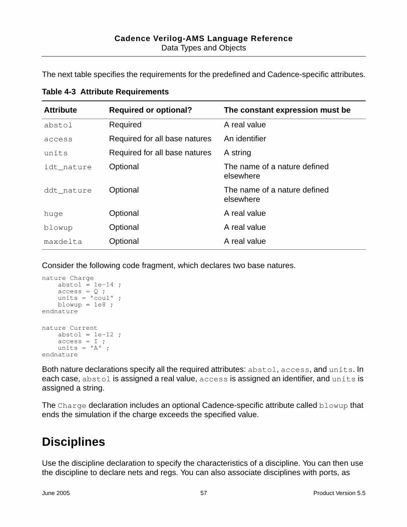
Cadence Verilog-AMS Language ReferenceData Types and Objects
The next table specifies the requirements for the predefined and Cadence-specific attributes.
Consider the following code fragment, which declares two base natures.
nature Chargeabstol = 1e-14 ;access = Q ;units = "coul" ;blowup = 1e8 ;
endnature
nature Currentabstol = 1e-12 ;access = I ;units = "A" ;
endnature
Both nature declarations specify all the required attributes: abstol, access, and units. Ineach case, abstol is assigned a real value, access is assigned an identifier, and units isassigned a string.
The Charge declaration includes an optional Cadence-specific attribute called blowup thatends the simulation if the charge exceeds the specified value.
Disciplines
Use the discipline declaration to specify the characteristics of a discipline. You can then usethe discipline to declare nets and regs. You can also associate disciplines with ports, as
Table 4-3 Attribute Requirements
Attribute Required or optional? The constant expression must be
abstol Required A real value
access Required for all base natures An identifier
units Required for all base natures A string
idt_nature Optional The name of a nature definedelsewhere
ddt_nature Optional The name of a nature definedelsewhere
huge Optional A real value
blowup Optional A real value
maxdelta Optional A real value
June 2005 57 Product Version 5.5

Cadence Verilog-AMS Language ReferenceData Types and Objects
discussed in Chapter 11, “Mixed-Signal Aspects of Verilog-AMS.” Cadence providesdefinitions of many commonly used disciplines in the disciplines.vams file. Forinformation, see Appendix C, “Standard Definitions.”
discipline_declaration ::=discipline discipline_identifier
[ discipline_description { discipline_description } ]enddiscipline
discipline_description ::=nature_binding
| domain_binding
nature_binding ::=potential nature_identifier ;
| flow nature_identifier ;
domain_binding ::=domain continuous ;
| domain discrete ;
You must declare a discipline at the top level. In other words, you cannot nest a disciplinedeclaration inside other discipline, nature, or module declarations. Discipline identifiers haveglobal scope, so you can use discipline identifiers to associate nets with disciplines (declarenets) inside any module.
Binding Natures with Potential and Flow
The disciplines that you declare can bind
■ One nature with potential
■ One nature with potential and a different nature with flow
■ Nothing with either potential or flow
A declaration of this latter form defines an empty discipline.
The following examples illustrate each of these forms.
The first example defines a single binding, one between potential and the nature Voltage.A discipline with a single binding is called a signal-flow discipline.
discipline voltagepotential Voltage ; // A signal-flow discipline must be bound to potential.
enddiscipline
The next declaration, for the electrical discipline, defines two bindings. Such adeclaration is called a conservative discipline.
discipline electricalpotential Voltage ;flow Current ;
enddiscipline
June 2005 58 Product Version 5.5

Cadence Verilog-AMS Language ReferenceData Types and Objects
When you define a conservative discipline, you must be sure that the nature bound topotential is different from the nature bound to flow.
The third declaration defines an empty discipline. If you do not explicitly specify a domain foran empty discipline, the domain is determined by the connectivity of the net.
discipline neutralenddiscipline
discipline interconnectdomain continuous
enddiscipline
In addition to declaring empty disciplines, you can also use a Verilog-A predefined emptydiscipline called wire.
Important
A wire in Verilog-A has no specified domain, so do not assume that it is digital.
Use an empty discipline when you want to let the components connected to a net determinewhich potential and flow natures are used for the net.
Binding Domains with Disciplines
The domain binding of a discipline indicates whether the signal value is an analog signal tobe represented in continuous time or a digital signal to be represented in discrete time. Thedefault domain is continuous for disciplines that are not empty. Signals in the continuousdomain always have real values. Signals in the discrete domain can have real, integer, orbinary (0, 1, x, or z) values.
The following example illustrates how to define a discipline for an analog signal. Because thedefault value for domain is continuous, the domain line in this example could be omitted.
discipline electricaldomain continuous ;potential Voltage ;flow Current ;
enddiscipline
The next example defines a discipline for a digital signal.
discipline logicdomain discrete ;
enddiscipline
June 2005 59 Product Version 5.5

Cadence Verilog-AMS Language ReferenceData Types and Objects
Disciplines and Domains of Wires and Undeclared Nets
Nets that do not have declared disciplines are evaluated as though they have emptydisciplines. The effective domain of such nets is determined by how the nets are used.
■ If the net is referenced in the digital context behavioral code or if its net type is other thanwire, then the domain of the net is assumed to be discrete.
■ If the net is bound only to ports and either has no declared net type or has a net type ofwire, then the net has no domain binding.
Discipline Precedence
Disciplines can be declared in several ways and if more than one of these ways applies to asingle net, discipline conflicts can arise. Verilog-A resolves conflicts with the followingprecedence.
Compatibility of Disciplines
Certain operations in Verilog-A, such as declaring branches, are allowed only if the disciplinesinvolved are compatible. Apply the following rules to determine whether any two disciplinesare compatible.
■ Any discipline is compatible with itself.
Kind of Discipline Declaration Precedence
A declaration from a module other than the module to which the netbelongs using an out-of-module reference. For example,
module example1 ;electrical example2.net ;
endmodule
Highestprecedence
A local declaration of a net in the module to which it belongs. For example,
module example2 ;electrical net ;
endmodule
`default_discipline used with qualifier only.
`default_discipline logic trireg ;
`default_discipline without qualifier or scope.
`default_discipline logic ;
Lowestprecedence
June 2005 60 Product Version 5.5

Cadence Verilog-AMS Language ReferenceData Types and Objects
■ An empty discipline is compatible with all disciplines.
■ Disciplines with the discrete domain attribute and the same signal value type, such asbit, real, or integer, are compatible.
■ Disciplines with different domain attributes are incompatible.
■ Other kinds of continuous disciplines are compatible or not compatible, as determinedby following paths through Figure 4-1 on page 61.
Figure 4-1 Analog Discipline Compatibility
Start
Potential
Potential
Flow
Flow
Disciplines arecompatible
Disciplines notcompatible
Yes
Yes
Yes
Yes
No
No
No
No
natures the same?
natures exist for bothdisciplines
natures exist for bothdisciplines
natures the same?
June 2005 61 Product Version 5.5

Cadence Verilog-AMS Language ReferenceData Types and Objects
Consider the following declarations.
nature Voltageaccess = V ;units = "V" ;abstol = 1u ;
endnature
nature Currentaccess = I ;units = "A" ;abstol = 1p ;
endnature
discipline emptydisenddiscipline
discipline electricalpotential Voltage ;flow Current ;
enddiscipline
discipline sig_flow_vpotential Voltage ;
enddiscipline
To determine whether the electrical and sig_flow_v disciplines are compatible, followthrough the discipline compatibility chart:
1. Both electrical and sig_flow_v have defined natures for potential. Take the Yesbranch.
2. In fact, electrical and sig_flow_v have the same nature for potential. Take theYes branch.
3. electrical has a defined nature for flow, but sig_flow_v does not. Take the Nobranch to the Disciplines are compatible end point.
Now add these declarations to the previous lists.
nature Positionaccess = x ;units = "m" ;abstol = 1u ;
endnature
nature Forceaccess = F ;units = "N" ;abstol = 1n ;
endnature
discipline mechanicalpotential Position ;flow force ;
enddiscipline
The electrical and mechanical disciplines are not compatible.
1. Both disciplines have defined natures for potential. Take the Yes branch.
June 2005 62 Product Version 5.5

Cadence Verilog-AMS Language ReferenceData Types and Objects
2. The Position nature is not the same as the Voltage nature. Take the No branch tothe Disciplines not compatible end point.
Net Disciplines
Use the net discipline declaration to associate nets and regs with previously defineddisciplines.
net_discipline_declaration ::=discipline_identifier [range] list_of_nets ;
| wire [range] list_of_nets ;
range ::=[ msb_expr : lsb_expr ]
list_of_nets ::=net_type
| net_type , list_of_nets
msb_expr ::=constant_expr
lsb_expression ::=constant_expr
net_type ::=net_identifier [range] [= constant_expr | constant_array_expr]
The initializers specified with the equals sign in the net_type can be used only when thediscipline_identifier is a continuous discipline. The solver uses the initializer, ifprovided, as a nodeset value for the potential of the net. A null value in theconstant_array_expr means that no nodeset value is being specified for that elementof the bus. The initializers cannot include out-of-module references.
A net declared without a range is called a scalar net. A net declared with a range is called avector net. In this release of Verilog-A, you cannot use parameters to define range limits.
magnetic inductor1, inductor2 ; //Declares two scalar netselectrical [1:10] node1 ; //Declares a vector netwire [3:0] connect1, connect2 ; //Declares two vector netselectrical [0:4] bus = {2.3,4.5,,6.0} ; //Declares vector net with nodeset values
The following example is illegal because a range, if defined, must be the first item after thediscipline identifier and then applies to all of the listed net identifiers.
electrical AVDD, AVSS, BGAVSS, PD, SUB, [6:1] TRIM ; // Illegal
Note: Cadence recommends that you specify the direction of a port before you specify thediscipline. For example, in the following example the directions for out and in are specifiedbefore the electrical discipline declaration.
Consider the following declarations.
discipline emptydisenddiscipline
June 2005 63 Product Version 5.5
Cadence Verilog-AMS Language ReferenceData Types and Objects
module comp1 (out, in, unknown1, unknown2) ;output out ;input in ;electrical out, in ;emptydis unknown1 ; // Declared with an empty disciplineanalog
V(out) <+ 2 * V(in)endmodule
Module comp1 has four ports: out, in, unknown1, and unknown2. The module declaresout and in as electrical ports and uses them in the analog block. The port unknown1is declared with an empty discipline and cannot be used in the analog block because thereis no way to access its signals. However, unknown1 can be used in the list of ports, where itinherits natures from the ports of module instances that connect to it.
Because unknown2 appears in the list of ports without being declared in the body of themodule, Verilog-A implicitly declares unknown2 as a scalar port with the default discipline.The default discipline type is wire, unless you use the `default_discipline compilerdirective to specify a different discipline. (For more information, see “Setting a DefaultDiscrete Discipline for Signals” on page 215.)
Now consider a different example.
module five_inputs( portbus );input [0:5] portbus;electrical [0:5] portbus;real x;analog begin
generate i ( 0,4 )V(portbus[i]) <+ 0.0;
endendmodule
The five_inputs module uses a port bus. Only one port name, portbus, appears in thelist of ports but inside the module portbus is defined with a range.
Modules comp1 and five_inputs illustrate the two ways you can use nets in a module.
■ You can define the ports of a module by giving a list of nets on the module statement.
■ You can describe the behavior of a module by declaring and using nets within the bodyof the module construct.
As you might expect, if you want to describe a conservative system, you must useconservative disciplines to define nets. If you want to describe a signal-flow or mixed signal-flow and conservative system, you can define nets with signal-flow disciplines.
As a result of port connections of analog nets, a single node can be bound to a number ofnets of different disciplines.
June 2005 64 Product Version 5.5

Cadence Verilog-AMS Language ReferenceData Types and Objects
Current contributions to a node that is bound only to disciplines that have only potentialnatures, are illegal. The potential of such a node is the sum of all potential contributions, butflow for such a node is not defined.
Nets of signal flow disciplines in modules must not be bound to inout ports and you must notcontribute potential to input ports.
To access the abstol associated with a nets’s potential or flow natures, use the form
net.potential.abstol
or
net.flow.abstol
For an example, see “Cross Event” on page 99.
Ground Nodes
Use the ground declaration to declare global reference nodes.
ground_declaration ::=ground list_of_nets ;
You use the ground declaration to specify an already declared net of continuous discipline.The node associated with that net then becomes the global reference node in the circuit. Ifused in behavioral code, the net must be used in only the differential source and probe forms.This requirement means that a form like V(gnd) is illegal but a form like V(in, gnd) islegal.
For example,
module loadedsrc(out);output out;electrical out;electrical gnd; // Declare a net of continuous discipline.ground gnd; // Declare the ground.parameter real srcval = 5.0;resistor #(.r(10K)) r1(out,gnd);analog begin
V(out) <+ V(in,gnd)*2; // Probe the voltage difference// between in and gnd.
endendmodule
Real Nets
Use the real net declaration to declare a data type that represents a real-valued physicalconnection between structural entities.
June 2005 65 Product Version 5.5
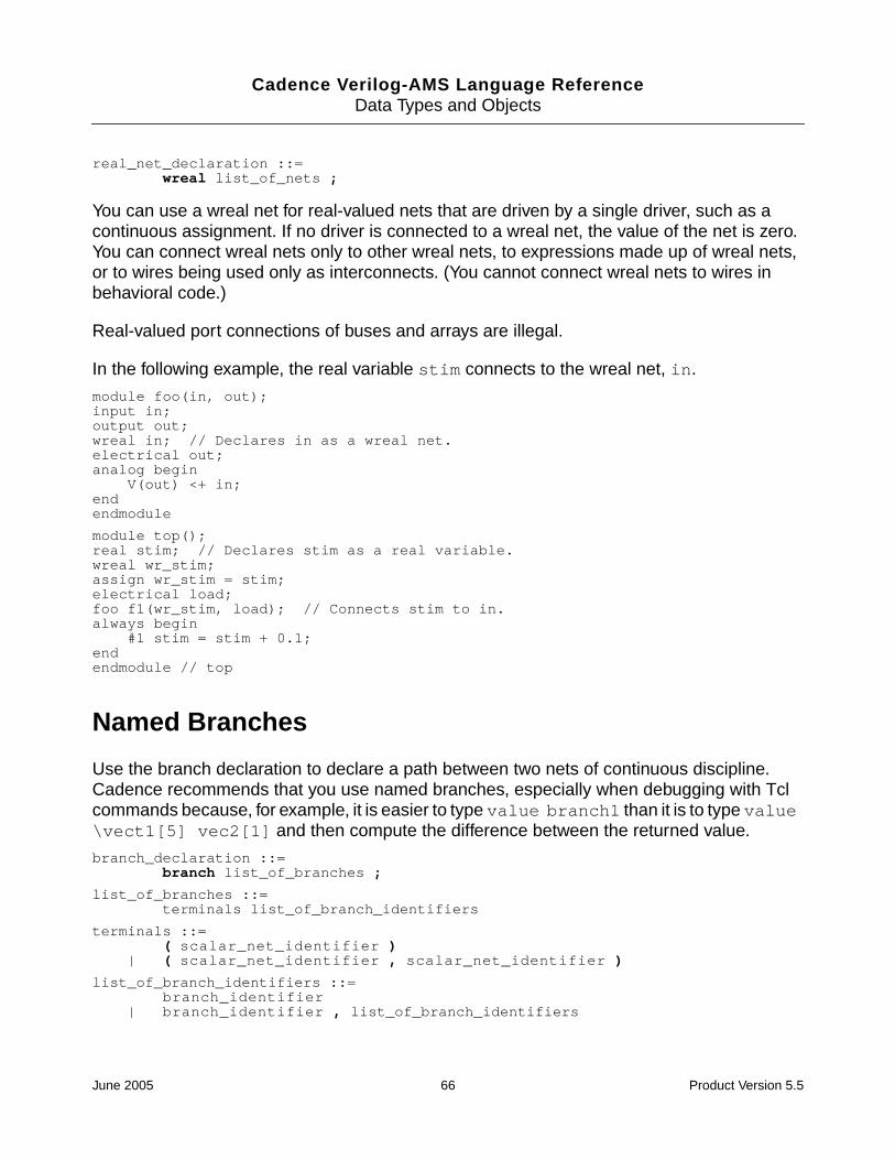
Cadence Verilog-AMS Language ReferenceData Types and Objects
real_net_declaration ::=wreal list_of_nets ;
You can use a wreal net for real-valued nets that are driven by a single driver, such as acontinuous assignment. If no driver is connected to a wreal net, the value of the net is zero.You can connect wreal nets only to other wreal nets, to expressions made up of wreal nets,or to wires being used only as interconnects. (You cannot connect wreal nets to wires inbehavioral code.)
Real-valued port connections of buses and arrays are illegal.
In the following example, the real variable stim connects to the wreal net, in.
module foo(in, out);input in;output out;wreal in; // Declares in as a wreal net.electrical out;analog begin
V(out) <+ in;endendmodule
module top();real stim; // Declares stim as a real variable.wreal wr_stim;assign wr_stim = stim;electrical load;foo f1(wr_stim, load); // Connects stim to in.always begin
#1 stim = stim + 0.1;endendmodule // top
Named Branches
Use the branch declaration to declare a path between two nets of continuous discipline.Cadence recommends that you use named branches, especially when debugging with Tclcommands because, for example, it is easier to type value branch1 than it is to type value\vect1[5] vec2[1] and then compute the difference between the returned value.
branch_declaration ::=branch list_of_branches ;
list_of_branches ::=terminals list_of_branch_identifiers
terminals ::=( scalar_net_identifier )
| ( scalar_net_identifier , scalar_net_identifier )
list_of_branch_identifiers ::=branch_identifier
| branch_identifier , list_of_branch_identifiers
June 2005 66 Product Version 5.5

Cadence Verilog-AMS Language ReferenceData Types and Objects
scalar_net_identifier must be either a scalar net or a single element of a vector net.
You can declare branches only in a module. You must not combine explicit and implicit branchdeclarations for a single branch. For more information, see “Implicit Branches” on page 67.
The scalar nets that the branch declaration associates with a branch are called the branchterminals. If you specify only one net, Verilog-A assumes that the other is ground. Thebranch terminals must have compatible disciplines. For more information, see “Compatibilityof Disciplines” on page 60.
Consider the following declarations.
voltage [5:0] vec1 ; // Declares a vector netvoltage [1:6] vec2 ; // Declares a vector netvoltage sca1 ; // Declares a scalar netvoltage sca2 ; // Declares a scalar netbranch (vec1[5],vec2[1]) branch1, (sca1,sca2) branch2 ;
branch1 is legally declared because each branch terminal is a single element of a vectornet. The second branch, branch2, is also legally declared because nodes sca1 and sca2are both scalar nets.
Implicit Branches
As Cadence recommends, you can refer to a named branch with only a single identifier.Alternatively, you might find it more convenient or clearer to refer to branches by their branchterminals. Most of the examples in this reference, including the following example, use thisform of implicit branch declaration. You must not, however, combine named and implicitbranch declarations for a single branch.
module diode (a, c) ;inout a, c ;electrical a, c ;parameter real rs=0, is=1e-14, tf=0, cjo=0, phi=0.7 ;parameter real kf=0, af=1, ef=1 ;
analog beginI(a, c) <+ is*(limexp((V(a, c)-rs*I(a, a))/$vt) - 1);I(a, c) <+ white_noise(2* `P_Q * I(a, c)) ;I(a, c) <+ flicker_noise(kf*pow(abs(I(a, c)),af),ef);
endendmodule
The previous example using implicit branches is equivalent to the following example usingnamed branches.
module diode (a, c) ;inout a, c ;electrical a, c ;branch (a,c) diode, (a,a) anode ; // Declare named branchesparameter real rs=0, is=1e-14, tf=0, cjo=0, phi=0.7 ;parameter real kf=0, af=1, ef=1 ;
June 2005 67 Product Version 5.5

Cadence Verilog-AMS Language ReferenceData Types and Objects
analog beginI(diode) <+ is*(limexp((V(diode)-rs*I(anode))/$vt) - 1);I(diode) <+ white_noise(2* `P_Q * I(diode)) ;I(diode) <+ flicker_noise(kf*pow(abs(I(diode)),af),ef);
endendmodule
June 2005 68 Product Version 5.5

Cadence Verilog-AMS Language Reference
5Statements for the Analog Block
This chapter describes the assignment statements and the procedural control constructs andstatements that the Cadence® Verilog®-A language supports within the analog block. Forinformation, see the indicated locations. The constructs and statements discussed include
■ Procedural Assignment Statements in the Analog Block on page 70
■ Branch Contribution Statement on page 70
■ Indirect Branch Assignment Statement on page 72
■ Sequential Block Statement on page 73
■ Conditional Statement on page 74
■ Case Statement on page 74
■ Loop statements, including
❑ Repeat Statement on page 75
❑ While Statement on page 76
❑ For Statement on page 76
■ Generate Statement on page 77
Verilog-A also supports statements for use in digital contexts. For more information, see the“Assignments” and “Behavioral Modeling” chapters, in the Verilog-XL Reference.
Assignment Statements
There are several kinds of assignment statements in Verilog-A: the procedural assignmentstatement, the branch contribution statement, and the indirect branch assignment statementare available for analog modeling. You use the procedural assignment statement to modifyinteger and real variables and you use the branch contribution and indirect branchassignment statements to modify branch values such as potential and flow.
June 2005 69 Product Version 5.5

Cadence Verilog-AMS Language ReferenceStatements for the Analog Block
In addition, Verilog-A supports the continuous assignment statement and the proceduralassignment statement for digital modeling. Continuous assignment statements can be usedonly outside of the initial, always, and analog blocks. For more information on thesestatements, see the “Assignments” chapter, in the Verilog-XL Reference.
Procedural Assignment Statements in the Analog Block
Use the procedural assignment statement to modify integer and real variables.
procedural_assignment ::=lexpr = expression ;
lexpr ::=integer_identifier
| real_identifier| array_element
array_element ::=integer_identifier [ constant_expression ]
| real_identifier [ constant_expression ]
The left-hand operand of the procedural assignment used in analog blocks must be amodifiable integer or real variable or an element of an integer or real array. The type of theleft-hand operand determines the type of the assignment.
The right-hand operand can be any arbitrary scalar expression constituted from legaloperands and operators.
In the following code fragment, the variable phase is assigned a real value. The value mustbe real because phase is defined as a real variable.
real phase ;analog begin
phase = idt( gain*V(in) ) ;
You can also use procedural assignment statements to modify array values. For example, ifr is declared as
real r[0:3], sum ;
you can make assignments such as
r[0] = 10.1 ;r[1] = 11.1 ;r[2] = 12.1 ;r[3] = 13.1 ;sum = r[0] + r[1] + r[2] + r[3] ;
Branch Contribution Statement
Use the branch contribution statement to modify signal values.
June 2005 70 Product Version 5.5
Cadence Verilog-AMS Language ReferenceStatements for the Analog Block
branch_contribution ::=bvalue <+ expression ;
bvalue ::=access_identifier ( analog_signal_list )
analog_signal_list ::=branch_identifier
| node_or_port_identifier| node_or_port_identifier , node_or_port_identifier
bvalue specifies a source branch signal. bvalue must consist of an access functionapplied to a branch. expression can be linear, nonlinear, or dynamic.
Branch contribution statements must be placed within the analog block.
As discussed in the following list, the branch contribution statement differs in important waysfrom the procedural assignment statement.
■ You can use the procedural assignment statement only for variables, whereas you canuse the branch contribution statement only for access functions.
■ Using the procedural assignment statement to assign a number to a variable overridesthe number previously contained in that variable. Using the branch contributionstatement, however, adds to any previous contribution. (Contributions to flow can beviewed as adding new flow sources in parallel with previous flow sources. Contributionsto value can be viewed as adding new value sources in series with previous valuesources.)
Evaluation of a Branch Contribution Statement
For source branch contributions, the simulator evaluates the branch contribution statementas follows:
1. The simulator evaluates the right-hand operand.
2. The simulator adds the value of the right-hand operand to any previously retained valuefor the branch.
3. At the end of the evaluation of the analog block, the simulator assigns the summed valueto the source branch.
For example, given a pair of nodes declared with the electrical discipline, the codefragment
V(n1, n2) <+ expr1 ;V(n1, n2) <+ expr2 ;
is equivalent to
V(n1, n2) <+ expr1 + expr2 ;
June 2005 71 Product Version 5.5

Cadence Verilog-AMS Language ReferenceStatements for the Analog Block
Creating a Switch Branch
Important
When you contribute a flow to a branch that already has a value retained forpotential, the simulator discards the value for potential and converts the branch to aflow source. Conversely, when you contribute a potential to a branch that alreadyhas a value retained for flow, the simulator discards the value for flow and convertsthe branch to a potential source. Branches converted from flow sources to potentialsources, and vice versa, are known as switch branches. For additional information,see “Switch Branches” on page 225.
Indirect Branch Assignment Statement
Use the indirect branch assignment statement when it is difficult to separate the target fromthe equation.
indirect_branch_assignment ::=target : equation ;
target ::=bvalue
equation ::=nexpr == expression
nexpr ::=bvalue
| ddt ( bvalue )| idt ( bvalue )| idtmod ( bvalue )
An indirect branch assignment has this format:
V(out) : V(in) == 0 ;
Read this as “find V(out) such that V(in) is zero.” This example says that out should bedriven with a voltage source and the voltage should be such that the given equation issatisfied. Any branches referenced in the equation are only probed and not driven, so in thisexample, V(in) acts as a voltage probe.
Indirect branch assignments can be used only within the analog block.
The next example models an ideal operational amplifier with infinite gain. The indirectassignment statement says “find V(out) such that V(pin, nin) is zero.”
module opamp (out, pin, nin) ;output out ;input pin, nin ;voltage out, pin, nin ;analog
June 2005 72 Product Version 5.5
Cadence Verilog-AMS Language ReferenceStatements for the Analog Block
V(out) : V(pin, nin) == 0 ; // Indirect assignmentendmodule
Indirect assignments are incompatible with assignments made with the branch contributionstatement. If you indirectly assign a value to a branch, you cannot then contribute to thebranch by using the branch contribution statement.
Sequential Block Statement
Use a sequential block when you want to group two or more statements together so that theyact like a single statement.
seq_block ::=begin [ : block_identifier { block_item_declaration } ]
{ statement }end
block_item_declaration ::=parameter_declarationinteger_declaration
| real_declaration
For information on statement, see “Defining Module Analog Behavior” on page 34.
The statements included in a sequential block run sequentially.
If you add a block identifier, you can also declare local variables for use within the block. Allthe local variables you declare are static. In other words, a unique location exists for eachlocal variable, and entering or leaving the block does not affect the value of a local variable.
The following code fragment uses two named blocks, declaring a local variable in each ofthem. Although the variables have the same name, the simulator handles them separatelybecause each variable is local to its own block.
integer j ;...
for ( j = 0 ; j < 10 ; j=j+1 ) beginif ( j%2 ) begin : odd
integer j ; // Declares a local variablej = j+1 ;$display ("Odd numbers counted so far = %d" , j ) ;
end else begin : eveninteger j ; // Declares a local variablej = j+1 ;$display ("Even numbers counted so far = %d" , j ) ;
endend
Each named block defines a new scope. For additional information, see “Scope Rules” onpage 45.
June 2005 73 Product Version 5.5

Cadence Verilog-AMS Language ReferenceStatements for the Analog Block
Conditional Statement
Use the conditional statement to run a statement under the control of specified conditions.
conditional_statement ::=if ( expression ) statement1[ else statement2 ]
If expression evaluates to a nonzero number (true), the simulator executesstatement1. If expression evaluates to zero (false) and the else statement is present,the simulator skips statement1 and executes statement2.
If expression consists entirely of genvar expressions, literal numerical constants,parameters, or the analysis function, statement1 and statement2 can include analogoperators.
The simulator always matches an else statement with the closest previous if that lacks anelse. In the following code fragment, for example, the first else goes with the inner if, asshown by the indentation.
if (index > 0)if (i > j) // The next else belongs to this if
result = i ;else // This else belongs to the previous if
result = j ;else $strobe ("Index < 0"); // This else belongs to the first if
The following code fragment illustrates a particularly useful form of the if-else construct.
if ((value > 0)&&(value <= 1)) $strobe("Category A");else if ((value > 1)&&(value <= 2)) $strobe("Category B");else if ((value > 2)&&(value <= 3)) $strobe("Category C");else if ((value > 3)&&(value <= 4)) $strobe("Category D");else $strobe("Illegal value");
The simulator evaluates the expressions in order. If any one of them is true, the simulator runsthe associated statement and ends the whole chain. The last else statement handles thedefault case, running if none of the other expressions is true.
Case Statement
Use the case construct to control which one of a series of statements runs.
case_statement ::=case ( expression ) case_item { case_item } endcase
case_item ::=test_expression { , test_expression } : statement
| default [ : ] statement
June 2005 74 Product Version 5.5
Cadence Verilog-AMS Language ReferenceStatements for the Analog Block
The default statement is optional. Using more than one default statement in a caseconstruct is illegal.
The simulator evaluates each test_expression in turn and compares it withexpression. If there is a match, the statement associated with the matchingtest_expression runs. If none of the expressions in text_expression matchesexpression and if you coded a default case_item, the default statement runs. If allcomparisons fail and you did not code a default case_item, none of the associatedstatements runs.
If expression and text_expression are genvar expressions, parameters, or theanalysis function, statement can include analog operators; otherwise, statementcannot include analog operators.
The following code fragment determines what range value is in. For example, if value is1.5 the first comparison fails. The second test_expression evaluates to 1 (true), whichmatches the case expression, so the $strobe("Category B") statement runs.
real value ;...
case (1)((value > 0)&&(value <= 1)) : $strobe("Category A");((value > 1)&&(value <= 2)) : $strobe("Category B");((value > 2)&&(value <= 3)) : $strobe("Category C");((value > 3)&&(value <= 4)) : $strobe("Category D");value <= 0 , value >= 4 : $strobe("Out of range");default $strobe("Error. Should never get here.");
endcase
Repeat Statement
Use the repeat statement when you want a statement to run a fixed number of times.
repeat_statement ::=repeat ( constant_expression ) statement
statement must not include any analog operators. For additional information, see “AnalogOperators” on page 130.
The following example code repeats the loop exactly 10 times while summing the first 10digits.
integer i, total ;...
i = 0 ;total = 0 ;repeat (10) begin
i = i + 1 ;total = total + i ;
end
June 2005 75 Product Version 5.5
Cadence Verilog-AMS Language ReferenceStatements for the Analog Block
While Statement
Use the while statement when you want to be able to leave a loop when an expression isno longer valid.
while_statement ::=while ( expression ) statement
The while loop evaluates expression at each entry into the loop. If expression isnonzero (true), statement runs. If expression starts out as zero (false), statementnever runs.
statement must not include any analog operators. For additional information, see “AnalogOperators” on page 130.
The following code fragment counts the number of random numbers generated before randbecomes zero.
integer rand, count ;...
rand = abs($random % 10) ;count = 0 ;while (rand) begin
count = count + 1 ;rand = abs($random % 10) ;
end ;$strobe ("Count is %d", count) ;
For Statement
Use the for statement when you want a statement to run a fixed number of times.
for_statement ::=for ( initial_assignment ; expression ;
step_assignment ) statement
If initial_assignment, expression, and step_assignment are genvarexpressions, the statement can include analog operators; otherwise, the statement mustnot include any analog operators. For additional information, see “Analog Operators” onpage 130.
Use initial_assignment to initialize an integer loop control variable that controls thenumber of times the loop executes. The simulator evaluates expression at each entry intothe loop. If expression evaluates to zero, the loop terminates. If expression evaluatesto a nonzero value, the simulator first runs statement and then runsstep_assignment. step_assignment is usually defined so that it modifies the loopcontrol variable before the simulator evaluates expression again.
June 2005 76 Product Version 5.5

Cadence Verilog-AMS Language ReferenceStatements for the Analog Block
For example, to sum the first 10 even numbers, the repeat loop given earlier could berewritten as a for loop.
integer j, total ;...
total = 0 ;for ( j = 2; j < 22; j = j + 2 )
total = total + j ;
Generate Statement
The generate statement is a looping construct that is unrolled at compile time. Use thegenerate statement to simplify your code or when you have a looping construct thatcontains analog operators. The generate statement can be used only within the analogblock. The generate statement is supported only for backward compatibility.
generate_statement ::=generate index_identifier ( start_expr ,end_expr [ , incr_expr ] ) statement
start_expr ::=constant_expression
end_expr ::=constant_expression
incr_expr ::=constant_expression
index_identifier is an identifier used in statement. When statement is unrolled,each occurrence of index_identifier found in statement is replaced by a constant.You must be certain that nothing inside statement modifies the index.
In the first unrolled instance of statement, the compiler replaces each occurrence ofindex_identifier by the value start_expr. In the second instance, the compilerreplaces each index_identifier by the value start_expr plus incr_expr. In thethird instance, the compiler replaces each index_identifier by the valuestart_expr plus twice the incr_expr. This process continues until the replacementvalue is greater than the value of end_expr.
If you do not specify incr_expr, it takes the value +1 if end_expr is greater thanstart_expr. If end_expr is less than start_expr, incr_expr takes the value -1 bydefault.
June 2005 77 Product Version 5.5

Cadence Verilog-AMS Language ReferenceStatements for the Analog Block
The values of the start_expr, end_expr, and incr_expr determine how thegenerate statement behaves.
As an example of using the generate statement, consider the following module, whichimplements an analog-to-digital converter.
`define BITS 4
module adc (in, out) ;input in ;output [0:`BITS - 1] out ;electrical in ;electrical [0:`BITS - 1] out ;parameter fullscale = 1.0, tdelay = 0.0, trantime = 10n ;real samp, half ;
analog beginhalf = fullscale/2.0 ;samp = V(in) ;generate i (`BITS - 1,0) begin // default increment = -1
V(out[i]) <+ transition(samp > half, tdelay, trantime);if (samp > half) samp = samp - half ;samp = 2.0 * samp ;
endendendmodule
Module adc is equivalent to the following module coded without using the generatestatement.
`define BITS 4module adc_unrolled (in, out) ;input in ;output [0:`BITS - 1] out ;electrical in;electrical [0:`BITS - 1] out ;parameter fullscale = 1.0, tdelay = 0.0, trantime = 10n ;real samp, half ;
analog beginhalf = fullscale/2.0 ;samp = V(in) ;V(out[3]) <+ transition(samp > half, tdelay, trantime);if (samp > half) samp = samp - half ;samp = 2.0 * samp ;V(out[2]) <+ transition(samp > half, tdelay, trantime);if (samp > half) samp = samp - half ;samp = 2.0 * samp ;
If And Then the generatestatement
start_expr > end_expr incr_expr > 0 does not execute
start_expr < end_expr incr_expr < 0 does not execute
start_expr = end_expr executes once
June 2005 78 Product Version 5.5

Cadence Verilog-AMS Language ReferenceStatements for the Analog Block
V(out[1]) <+ transition(samp > half, tdelay, trantime);if (samp > half) samp = samp - half ;samp = 2.0 * samp ;V(out[0]) <+ transition(samp > half, tdelay, trantime);if (samp > half) samp = samp - half ;samp = 2.0 * samp ;
endendmodule
Note: Because the generate statement is unrolled at compile time, you cannot use theSimVision debugging tool to examine the value of index_identifier or to evaluateexpressions that contain index_identifier. For example, if index_identifier isi, you cannot use a debugging command like print i nor can you use a command likeprint{a[i]}.
June 2005 79 Product Version 5.5

Cadence Verilog-AMS Language ReferenceStatements for the Analog Block
June 2005 80 Product Version 5.5

Cadence Verilog-AMS Language Reference
6Operators for Analog Blocks
This chapter describes the operators that you can use in analog blocks and explains how touse them to form expressions. For basic definitions, see
■ Unary Operators on page 83
■ Binary Operators on page 85
■ Bitwise Operators on page 88
■ Ternary Operator on page 89
For information about precedence and short-circuiting, see
■ Operator Precedence on page 90
■ Expression Short-Circuiting on page 90
Verilog-A also supports additional operators for use in digital contexts. For more information,see the “Expressions” chapter, in the Verilog-XL Reference.
June 2005 81 Product Version 5.5

Cadence Verilog-AMS Language ReferenceOperators for Analog Blocks
Overview of Operators
An expression is a construct that combines operands with operators to produce a result thatis a function of the values of the operands and the semantic meaning of the operators. Anylegal operand is also an expression. You can use an expression anywhere Verilog-A requiresa value.
A constant expression is an expression whose operands are constant numbers andpreviously defined parameters and whose operators all come from among the unary, binary,and ternary operators described in this chapter.
All of the operators (except ==, !=, ===, and !==), functions, and statements used incontinuous contexts report an error if the expressions they operate on contain x or z bits.
The operators listed below, with the single exception of the conditional operator, associatefrom left to right. That means that when operators have the same precedence, the onefarthest to the left is evaluated first. In this example
A + B - C
the simulator does the addition before it does the subtraction.
When operators have different precedence, the operator with the highest precedence (thesmallest precedence number) is evaluated first. In this example
A + B / C
the division (which has a precedence of 2) is evaluated before the addition (which has aprecedence of 3). For information on precedence, see “Operator Precedence” on page 90.
You can change the order of evaluation with parentheses. If you code
(A + B) / C
the addition is evaluated before the division.
The operators divide into three groups, according to the number of operands the operatorrequires. The groups are the unary operators, the binary operators, and the ternary operator.
June 2005 82 Product Version 5.5
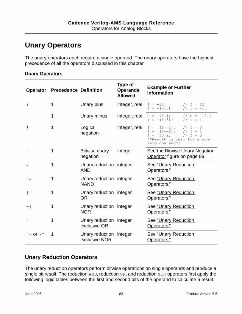
Cadence Verilog-AMS Language ReferenceOperators for Analog Blocks
Unary Operators
The unary operators each require a single operand. The unary operators have the highestprecedence of all the operators discussed in this chapter.
Unary Reduction Operators
The unary reduction operators perform bitwise operations on single operands and produce asingle bit result. The reduction AND, reduction OR, and reduction XOR operators first apply thefollowing logic tables between the first and second bits of the operand to calculate a result.
Unary Operators
Operator Precedence DefinitionType ofOperandsAllowed
Example or FurtherInformation
+ 1 Unary plus Integer, real I = +13; // I = 13I = +(-13); // I = -13
- 1 Unary minus Integer, real R = -13.1; // R = -13.1I = -(4-5); // I = 1
! 1 Logicalnegation
Integer, real I = !(1==1); // I = 0I = !(1==2); // I = 1I = !13.2; // I = 0/*Result is zero for a non-zero operand*/
~ 1 Bitwise unarynegation
Integer See the Bitwise Unary NegationOperator figure on page 89.
& 1 Unary reductionAND
integer See “Unary ReductionOperators.”
~& 1 Unary reductionNAND
integer See “Unary ReductionOperators.”
| 1 Unary reductionOR
integer See “Unary ReductionOperators.”
~| 1 Unary reductionNOR
integer See “Unary ReductionOperators.”
^ 1 Unary reductionexclusive OR
integer See “Unary ReductionOperators.”
^~ or ~^ 1 Unary reductionexclusive NOR
integer See “Unary ReductionOperators.”
June 2005 83 Product Version 5.5

Cadence Verilog-AMS Language ReferenceOperators for Analog Blocks
Then for the second and subsequent steps, these operators apply the same logic table to theprevious result and the next bit of the operand, continuing until there is a single bit result.
The reduction NAND, reduction NOR, and reduction XNOR operators are calculated in the sameway, except that the result is inverted.
Reduction operators can be used in the initial and always blocks of modules but are notsupported in the analog block of Verilog-AMS modules.
Unary Reduction AND Operator
& 0 1
0 0 0
1 0 1
Unary Reduction OR Operator
| 0 1
0 0 1
1 1 1
Unary Reduction Exclusive OR Operator
^ 0 1
0 0 1
1 1 0
June 2005 84 Product Version 5.5

Cadence Verilog-AMS Language ReferenceOperators for Analog Blocks
Binary Operators
The binary operators each require two operands.
Binary Operators
Operator Precedence DefinitionType ofOperandsAllowed
Example or FurtherInformation
+ 3 a plus b Integer, real R = 10.0 + 3.1; // R = 13.1
- 3 a minus b Integer, real I = 10 - 13; // I = -3
* 2 a multiplied byb
Integer, real R = 2.2 * 2.0; // R = 4.4
/ 2 a divided by b Integer, real I = 9 / 4; // I = 2R = 9.0 / 4; // R = 2.25
% 2 a modulo b Integer, real I = 10 % 5; // I = 0I = -12 % 5; // I = -2R = 10 % 3.75 // R = 2.5/*The result takes sign of thefirst operand.*/
< 5 a less than b;evaluates to 0or 1
Integer, real I = 5 < 7; // I = 1I = 7 < 5; // I = 0
> 5 a greater thanb; evaluates to0 or 1
Integer, real I = 5 > 7; // I = 0I = 7 > 5; // I = 1
<= 5 a less than orequal to b;evaluates to 0or 1
Integer, real I = 5.0 <= 7.5; // I = 1I = 5.0 <= 5.0; // I = 1I = 5 <= 4; // I = 0
>= 5 a greater thanor equal to b;evaluates to 0or 1
Integer, real I = 5.0 >= 7; // I = 0I = 5.0 >= 5; // I = 1I = 5.0 >= 4.8; // I = 1
== 6 a equal to b;evaluates to 0,1, or x (if any bitof a or b is x orz).
Integer, real I = 5.2 == 5.2; // I = 1I = 5.2 == 5.0; // I = 0I = 1 == 1'bx; // I = x
June 2005 85 Product Version 5.5

Cadence Verilog-AMS Language ReferenceOperators for Analog Blocks
!= 6 a not equal tob; evaluates to0, 1, or x (if anybit of a or b is xor z).
Integer, real I = 5.2 != 5.2; // I = 0I = 5.2 != 5.0; // I = 1
=== 6 case equality; xand z bitsincluded;evaluates to 0or 1
integer I = 1 === 1'bx; // I = 0
!== 6 case inequality;X and Z bitsincluded;evaluates to 0or 1
integer I = 1 !== 1'bx; // I = 1
&& 10 Logical AND;evaluates to 0or 1
Integer, real I = (1==1)&&(2==2); // I = 1I = (1==2)&&(2==2); // I = 0I = -13 && 1; // I = 1
|| 11 Logical OR;evaluates to 0or 1
Integer, real I = (1==2)||(2==2); // I = 1I = (1==2)||(2==3); // I = 0I = 13 || 0; // I = 1
& 7 Bitwise binaryAND
Integer See the Bitwise Binary ANDOperator figure on page 88.
| 9 Bitwise binaryOR
Integer See the Bitwise Binary OROperator figure on page 88.
^ 8 Bitwise binaryexclusive OR
Integer See the Bitwise Binary ExclusiveOR Operator figure on page 88.
^~ 8 Bitwise binaryexclusive NOR(Same as ~^)
Integer See the Bitwise Binary ExclusiveNOR Operator figure on page 88.
~^ 8 Bitwise binaryexclusive NOR(Same as ^~)
Integer See the Bitwise Binary ExclusiveNOR Operator figure on page 88.
Binary Operators, continued
Operator Precedence DefinitionType ofOperandsAllowed
Example or FurtherInformation
June 2005 86 Product Version 5.5

Cadence Verilog-AMS Language ReferenceOperators for Analog Blocks
<< 4 a shifted b bitsleft
Integer I = 1 << 2; // I = 4I = 2 << 2; // I = 8I = 4 << 2; // I = 16
>> 4 a shifted b bitsright
Integer I = 4 >> 2; // I = 1I = 2 >> 2; // I = 0
or 11 Event OR Eventexpression
@(initial_step orcross(V(vin)-1))
Binary Operators, continued
Operator Precedence DefinitionType ofOperandsAllowed
Example or FurtherInformation
June 2005 87 Product Version 5.5
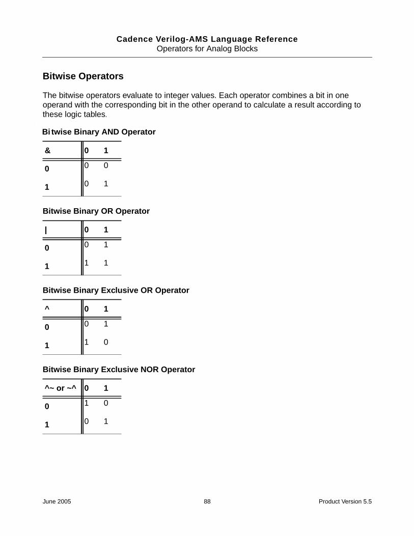
Cadence Verilog-AMS Language ReferenceOperators for Analog Blocks
Bitwise Operators
The bitwise operators evaluate to integer values. Each operator combines a bit in oneoperand with the corresponding bit in the other operand to calculate a result according tothese logic tables.
Bi twise Binary AND Operator
& 0 1
0 0 0
1 0 1
Bitwise Binary OR Operator
| 0 1
0 0 1
1 1 1
Bitwise Binary Exclusive OR Operator
^ 0 1
0 0 1
1 1 0
Bitwise Binary Exclusive NOR Operator
^~ or ~^ 0 1
0 1 0
1 0 1
June 2005 88 Product Version 5.5

Cadence Verilog-AMS Language ReferenceOperators for Analog Blocks
Ternary Operator
There is only one ternary operator, the conditional operator. The conditional operator has thelowest precedence of all the operators listed in this chapter.
A complete conditional operator expression looks like this:
conditional_expr ? true_expr : false_expr
If conditional_expr is true, the conditional operator evaluates to true_expr,otherwise to false_expr.
The conditional operator is right associative.
This operator performs the same function as the if-else construct. For example, thecontribution statement
V(out) <+ V(in) > 2.5 ? 0.0 : 5.0 ;
is equivalent to
If (V(in) > 2.5)V(out) <+ 0.0 ;
elseV(out) <+ 5.0 ;
Bitwise Unary Negation Operator
~
0 1
1 0
Conditional Operator
Operator Precedence DefinitionType ofOperandsAllowed
Example or FurtherInformation
?: 12 exp ? t_exp :f_exp
Validexpressions
I= 2==3 ? 1:0; // I = 0R= 1==1 ? 1.0:0.0; // R=1.0
June 2005 89 Product Version 5.5

Cadence Verilog-AMS Language ReferenceOperators for Analog Blocks
Operator Precedence
The following table summarizes the precedence information for the unary, binary, and ternaryoperators. Operators at the top of the table have higher precedence than operators lower inthe table.
Expression Short-Circuiting
Sometimes the simulator can determine the value of an expression containing logical AND( && ), logical OR ( || ), or bitwise AND ( &) without evaluating the entire expression. Bytaking advantage of such expressions, the simulator operates more efficiently.
Precedence Operators
1 + - ! ~ (unary) Highest precedence
2 * / %
3 + - (binary)
4 << >>
5 < <= > >=
6 == != === !==
7 &
8 ^ ~^ ^~
9 |
10 &&
11 ||
12 ?: (conditional operator) Lowest precedence
June 2005 90 Product Version 5.5

Cadence Verilog-AMS Language Reference
7Built-In Mathematical Functions
This chapter describes the mathematical functions provided by the Cadence® Verilog®-Alanguage. These functions include
■ Standard Mathematical Functions on page 92
■ Trigonometric and Hyperbolic Functions on page 92
■ Controlling How Math Domain Errors Are Handled on page 93
Because the simulator uses differentiation to evaluate expressions, Cadence recommendsthat you use only mathematical expressions that are continuously differentiable. To preventrun-time domain errors, make sure that each argument is within a function’s domain.
June 2005 91 Product Version 5.5

Cadence Verilog-AMS Language ReferenceBuilt-In Mathematical Functions
Standard Mathematical Functions
These are the standard mathematical functions supported by Verilog-A. The operands mustbe integers or real numbers.
Trigonometric and Hyperbolic Functions
These are the trigonometric and hyperbolic functions supported by Verilog-A. The operandsmust be integers or real numbers. The simulator converts operands to real numbers ifnecessary.
Function Description Domain Returned Value
abs(x) Absolute All x Integer, if x is integer;otherwise, real
ceil(x) Smallest integer largerthan or equal to x
All x Integer
exp(x) Exponential. See also“Limited ExponentialFunction” on page 131.
Real
floor(x) Largest integer less thanor equal to x
All x Integer
ln(x) Natural logarithm x > 0 Real
log(x) Decimal logarithm x > 0 Real
max(x,y) Maximum All x, all y Integer, if x and y areintegers; otherwise, real
min(x,y) Minimum All x, all y Integer, if x and y areintegers; otherwise, real
pow(x,y) Power of (xy) All y, if x > 0y > 0, if x = 0y integer, if x < 0
Real
sqrt(x) Square root x >= 0 Real
June 2005 92 Product Version 5.5

Cadence Verilog-AMS Language ReferenceBuilt-In Mathematical Functions
The trigonometric and hyperbolic functions require operands specified in radians.
Controlling How Math Domain Errors Are Handled
To control how math domain errors are handled in AHDL, you can use the optionsahdldomainerror parameter. (In Verilog-AMS code, this parameter can be used only in theanalog block.) This parameter controls how domain (out-of-range) errors in AHDL mathfunctions such as log or atan are handled and determines what kind of message is issuedwhen a domain error is found.
The ahdldomainerror parameter format is
Name options ahdldomainerror=value
where the syntax items are defined as follows.
Function Description Domain
sin(x) Sine All x
cos(x) Cosine All x
tan(x) Tangent, n is odd
asin(x) Arc-sine -1 <= x <= 1
acos(x) Arc-cosine -1 <= x <= 1
atan(x) Arc-tangent All x
atan2(x,y) Arc-tangent of x/y All x, all y
hypot(x,y) Sqrt(x2 + y2) All x, all y
sinh(x) Hyperbolic sine All x
cosh(x) Hyperbolic cosine All x
tanh(x) Hyperbolic tangent All x
asinh(x) Arc-hyperbolic sine All x
acosh(x) Arc-hyperbolic cosine x >= 1
atanh(x) Arc-hyperbolic tangent -1 <= x <= 1
x nπ2---
≠
June 2005 93 Product Version 5.5

Cadence Verilog-AMS Language ReferenceBuilt-In Mathematical Functions
For example, you might have the following in a Spectre control file to ensure that simulationstops when a domain error occurs.
myoption options ahdldomainerror=error
Name The unique name you give to the options statement. The Spectresimulator uses this name to identify this statement in error orannotation messages
value
none If a domain error occurs, no message is issued. The simulationcontinues with the argument of the math function set to the nearestreasonable number to the invalid argument.
For example, if the `sqrt() function is passed a negative value,the argument is reset to 0.0.
warning If a domain error occurs, a warning message is issued. Thesimulation continues with the argument of the math function set tothe nearest reasonable number to the invalid argument. This is thedefault.
For example, if the `sqrt() function is passed a negative value,the argument is reset to 0.0.
error If a domain error occurs, a message such as the following (which,in this example, indicates a problem with the `sqrt function) isissued.
Fatal error found by spectre during IC analysis, duringtransient analysis `mytran'."acosh.va" 20: r1: negative argument passed to `sqrt()'.(value passed was -1.000000)
The simulation then terminates.
June 2005 94 Product Version 5.5

Cadence Verilog-AMS Language Reference
8Detecting and Using Events
During a simulation, the simulator generates analog and digital events that you can use tocontrol the behavior of your modules. The simulator generates some of these eventsautomatically at various stages of the simulation. The simulator generates other events inaccordance with criteria that you specify. Your modules can detect either kind of event anduse the occurrences to determine whether specified statements run.
This chapter discusses the following kinds of events
■ Initial_step Event on page 97
■ Final_step Event on page 98
■ Cross Event on page 99
■ Above Event on page 100
■ Timer Event on page 102
The Cadence Verilog®-AMS language also supports events for digital contexts. For moreinformation, see the “Event Control” section in the “Behavioral Modeling” chapter of theVerilog-XL Reference.
June 2005 95 Product Version 5.5

Cadence Verilog-AMS Language ReferenceDetecting and Using Events
Detecting and Using Events
Use the @ operator to run a statement under the control of particular events.
event_control_statement ::=@ ( event_expr ) statement ;
event_expr ::=simple_event [ or event_expr ]
simple_event ::=initial_step_event
| final_step_event| cross_event| timer_event| expression_event| named_event| posedge_event| negedge_event
statement is the statement controlled by event_expr. The statement must not be acontribution statement and must not contain any analog operators. The statement:
■ Cannot include expressions that use analog operators.
■ Cannot be a contribution statement.
simple_event is an event that you want to detect. The behavior depends on the context:
■ In the analog context, when, and only when, simple_event occurs, the simulator runsstatement. Otherwise, statement is skipped. The kinds of simple events aredescribed in the following sections.
■ In the digital context, processing of the block is prevented until the event expressionevaluates to true.
If you want to detect more than one kind of event, you can use the event or operator. Any oneof the events joined with the event or operator causes the simulator to run statement. Thefollowing fragment, for example, sets V(out) to zero or one at the beginning of the analysisand at any time V(sample) crosses the value 2.5.
analog begin@(initial_step or cross(V(sample)-2.5, +1)) begin
vout = (V(in) > 2.5) ;endV(out) <+ vout ;
end
For information on See
initial_step_event “Initial_step Event” on page 97
final_step_event “Final_step Event” on page 98
June 2005 96 Product Version 5.5

Cadence Verilog-AMS Language ReferenceDetecting and Using Events
Initial_step Event
The simulator generates an initial_step event during the solution of the first point in specifiedanalyses, or, if no analyses are specified, during the solution of the first point of everyanalysis. Use the initial_step event to perform an action that should occur only at thebeginning of an analysis.
initial_step_event ::=initial_step [ ( analysis_list ) ]
analysis_list ::=analysis_name { , analysis_name }
analysis_name ::="analysis_identifier"
If the string in analysis_identifier matches the analysis being run, the simulatorgenerates an initial_step event during the solution of the first point of that analysis. If you donot specify analysis_list, the simulator generates an initial_step event during thesolution of the first point, or initial DC analysis, of every analysis.
In this release of Verilog-A, the initial_step event is supported for the ac, noise, tran, anddc sweep analyses.
The initial_step event is predefined, so you cannot redefine it in your model.
You can detect initial_step events only from within the analog block.
cross_event “Cross Event” on page 99
above_event “Above Event” on page 100
timer_event “Timer Event” on page 102
expression_event “Event Control” in Chapter 8 of Verilog-XLReference
named_event “Event Control” in Chapter 8 of Verilog-XLReference
posedge_event “Event Control” in Chapter 8 of Verilog-XLReference
negedge_event “Event Control” in Chapter 8 of Verilog-XLReference
For information on See
June 2005 97 Product Version 5.5

Cadence Verilog-AMS Language ReferenceDetecting and Using Events
Final_step Event
The simulator generates a final_step event during the solution of the last point in specifiedanalyses, or, if no analyses are specified, during the solution of the last point of everyanalysis. Use the final_step event to perform an action that should occur only at the end ofan analysis.
final_step_event ::=final_step [ ( analysis_list ) ]
analysis_list ::=analysis_name { , analysis_name }
analysis_name ::="analysis_identifier"
If the string in analysis_identifier matches the analysis being run, the simulatorgenerates a final_step event during the solution of the last point of that analysis. If you do notspecify analysis_list, the simulator generates a final_step event during the solution ofthe last point of every analysis.
In this release of Verilog-A, the final_step event is supported for the ac, noise, tran, anddc sweep analyses.
The final_step event is predefined, so you cannot redefine it in your model.
You can detect final_step events only from within the analog block.
You might use the final_step event to print out the results at the end of an analysis. Forexample, module bit_error_rate measures the bit-error of a signal and prints out theresults at the end of the analysis. (This example also uses the timer event, which is discussedin “Timer Event” on page 102.)
module bit_error_rate (in, ref) ;input in, ref ;electrical in, ref ;parameter real period=1, thresh=0.5 ;integer bits, errors ;analog begin
@(initial_step) beginbits = 0 ;errors = 0 ; // Initialize the variables
end@(timer(0, period)) begin
if ((V(in) > thresh) != (V(ref) > thresh))errors = errors + 1; // Check for errors each period
bits = bits + 1 ;end@(final_step)
$strobe("Bit error rate = %f%%", 100.0 * errors/bits );endendmodule
June 2005 98 Product Version 5.5

Cadence Verilog-AMS Language ReferenceDetecting and Using Events
Cross Event
According to criteria you set, the simulator can generate a cross event when an expressioncrosses zero in a specified direction. Use the cross function to specify which crossingsgenerate a cross event.
cross_function ::=cross (expr1 [ , direction [ , time_tol [ , expr_tol ] ] ] )
direction ::=+1 | 0 | -1
time_tol ::=expr2
expr_tol ::=expr3
expr1 is the real expression whose zero crossing you want to detect.
direction is an integer expression set to indicate which zero crossings the simulatorshould detect.
time_tol is a constant expression with a positive value, which is the largest time intervalthat you consider negligible.
expr_tol is a constant expression with a positive value, which is the largest difference thatyou consider negligible. If you specify expr_tol, both it and time_tol must be satisfied.If you do not specify expr_tol, the simulator uses the value of its own reltol parameter.
In addition to generating a cross event, the cross function also controls the time steps toaccurately resolve each detected crossing.
The cross function is subject to the restrictions listed in “Restrictions on Using AnalogOperators” on page 131.
The following example illustrates how you might use the cross function and event. Thecross function generates a cross event each time the sample voltage increases through the
If you want to Then
Detect all zero crossings Do not specify direction, or setdirection equal to 0
Detect only zero crossings where thevalue is increasing
Set direction equal to +1
Detect only zero crossings where thevalue is decreasing
Set direction equal to -1
June 2005 99 Product Version 5.5

Cadence Verilog-AMS Language ReferenceDetecting and Using Events
value 2.5. expr_tol is specified as the abstol associated with the potential nature of thenet sample.
module samphold (in, out, sample) ;output out ;input in, sample ;electrical in, out, sample ;real hold ;
analog begin@(cross(V(sample)-2.5, +1, 0.01n, sample.potential.abstol))
hold = V(in) ;V(out) <+ transition(hold, 0, 10n) ;
endendmodule
Above Event
According to criteria you set, the simulator can generate an above event when an expressionbecomes greater than or equal to zero. Use the above function to specify when the simulatorgenerates an above event. An above event can be generated and detected duringinitialization. By contrast, a cross event can be generated and detected only after at least onetransient time step is complete.
The above function is a Cadence language extension.
above_function ::=above (expr1 [ , time_tol [ , expr_tol ] ] )
time_tol ::=expr2
expr_tol ::=expr3
expr1 is a real expression whose value is to be compared with zero.
time_tol is a constant real expression with a positive value, which is the largest timeinterval that you consider negligible.
expr_tol is a constant real expression with a positive value, which is the largest differencethat you consider negligible. If you specify expr_tol, both it and time_tol must besatisfied. If you do not specify expr_tol, the simulator uses the value of its own reltolparameter.
During a transient analysis, after t = 0, the above function behaves the same as a crossfunction with the following specification.
cross(expr1 , 1 , time_tol, expr_tol )
During a transient analysis, the above function controls the time steps to accurately resolvethe time when expr1 rises to zero or above.
June 2005 100 Product Version 5.5

Cadence Verilog-AMS Language ReferenceDetecting and Using Events
The above function is subject to the restrictions listed in “Restrictions on Using AnalogOperators” on page 131.
The following example illustrates how you might use the above function. The functiongenerates an above event each time the analog voltage increases through the value 3.5 ordecreases through the value 1.5.
connectmodule elect2logic_2(aVal, dVal);input aVal;output dVal;electrical aVal;logic dVal;parameter real thresholdLo = 1.5;parameter real thresholdHi = 3.5;
integer iVal;
assign dVal = iVal; // direct driver/receiver propagation
always @(above(V(aVal) - thresholdHi))iVal = 1’b1;
always @(above(thresholdLo - V(aVal)))iVal = 1’b0;
endmodule
The usefulness of the above function becomes apparent when elect2logic is insertedacross the in port of the inv I1 instance in the following module.
module top;electrical src, gnd;logic out;ground gnd;
vsource #(.dc(5)) V1(src,gnd);inv I1(src,out);
endmodule
module inv(in,out);input in;output out;
assign out = !in;endmodule
The modules describe a circuit where an analog DC voltage source, V1, generates a constant5 volt signal that drives a digital inverter. Using the above function in elect2logic sets thevalues correctly at the end of the initialization. However, if the above function is replaced withthe cross function, the value of out is set to 1’b1 at the end of the initialization and retainsthat value throughout the transient analysis. This incorrect result is caused by the fact thatcross events cannot be generated or detected during initialization.
June 2005 101 Product Version 5.5

Cadence Verilog-AMS Language ReferenceDetecting and Using Events
Timer Event
According to criteria you set, the simulator can generate a timer event at specified timesduring a simulation. Use the timer function to specify when the simulator generates a timerevent.
Do not use the timer function inside conditional statements.
timer_function ::=timer ( start_time [ , period [ , timetol ]] )
start_time is a dynamic expression specifying an initial time. The simulator places a firsttime step at, or just beyond, the start_time that you specify and generates a timer event.
period is a dynamic expression specifying a time interval. The simulator places time stepsand generates events at each multiple of period after start_time.
timetol is a constant expression specifying how close a placed time point must be to theactual time point.
The module squarewave, below, illustrates how you might use the timer function to generatetimer events. In squarewave, the output voltage changes from positive to negative or fromnegative to positive at every time interval of period/2.
module squarewave (out)output out ;electrical out ;parameter period = 1.0 ;integer x ;
analog begin@(initial_step) x = 1 ;@(timer(0, period/2)) x = -x ;V(out) <+ transition(x, 0.0, period/100.0 ) ;
endendmodule
June 2005 102 Product Version 5.5

Cadence Verilog-AMS Language Reference
9Simulator Functions
This chapter describes the Cadence® Verilog®-A language simulator functions. The simulatorfunctions let you access information about a simulation and manage the simulation’s currentstate. You can also use the simulator functions to display and record simulation results.
For information about using simulator functions, see
■ Announcing Discontinuity on page 105
■ Bounding the Time Step on page 107
■ Finding When a Signal Is Zero on page 107
■ Querying the Simulation Environment on page 108
■ Obtaining and Setting Signal Values on page 110
■ Determining the Current Analysis Type on page 116
■ Examining Drivers on page 114
■ Implementing Small-Signal AC Sources on page 118
■ Implementing Small-Signal Noise Sources on page 118
■ Generating Random Numbers on page 120
■ Generating Random Numbers in Specified Distributions on page 121
■ Determining Whether a Parameter Value is Overridden on page 126
■ Interpolating with Table Models on page 127
For information on analog operators and filters, see
■ Limited Exponential Function on page 131
■ Time Derivative Operator on page 131
■ Time Integral Operator on page 132
June 2005 103 Product Version 5.5

Cadence Verilog-AMS Language ReferenceSimulator Functions
■ Circular Integrator Operator on page 133
■ Delay Operator on page 135
■ Transition Filter on page 136
■ Slew Filter on page 140
■ Implementing Laplace Transform S-Domain Filters on page 141
■ Implementing Z-Transform Filters on page 147
For descriptions of functions used to control input and output, see
■ Displaying Results on page 151
■ Working with Files on page 156
For descriptions of functions used to control the simulator, see
■ Exiting to the Operating System on page 162
For a description of the $pwr function, which is used to specify power consumption in amodule, see
■ Specifying Power Consumption on page 155
For information on using user-defined functions in the Verilog-A language, see
■ Declaring an Analog User-Defined Function on page 163
■ Calling a User-Defined Analog Function on page 165
June 2005 104 Product Version 5.5

Cadence Verilog-AMS Language ReferenceSimulator Functions
Announcing Discontinuity
Use the $discontinuity function to tell the simulator about a discontinuity in signalbehavior.
discontinuity_function ::=$discontinuity[ (constant_expression) ]
constant_expression, which must be zero or a positive integer, is the degree of thediscontinuity. For example, $discontinuity, which is equivalent to$discontinuity(0), indicates a discontinuity in the equation, and $discontinuity(1)indicates a discontinuity in the slope of the equation.
You do not need to announce discontinuities created by switch branches or built-in functionssuch as transition and slew.
Be aware that using the $discontinuity function does not guarantee that the simulatorwill be able to handle a discontinuity successfully. If possible, you should avoid discontinuitiesin the circuits you model.
The following example shows how you might use the $discontinuity function whiledescribing the behavior of a source that generates a triangular wave. As the Triangular Wavefigure on page 105 shows, the triangular wave is continuous, but as the Triangular Wave FirstDerivative figure on page 105 shows, the first derivative of the wave is discontinuous.
Triangular Wave
Triangular Wave First Derivative
The module trisource describes this triangular wave source.
module trisource (vout) ;output vout ;voltage vout ;parameter real wavelength = 10.0, amplitude = 1.0 ;integer slope ;real wstart ;
June 2005 105 Product Version 5.5

Cadence Verilog-AMS Language ReferenceSimulator Functions
analog begin@(timer(0, wavelength)) begin
slope = +1 ;wstart = $abstime ;$discontinuity (1); // Change from neg to pos slope
end@(timer(wavelength/2, wavelength)) begin
slope = -1 ;wstart = $abstime ;$discontinuity (1); // Change from pos to neg slope
endV(vout) <+ amplitude * slope * (4 * ($abstime - wstart) / wavelength-1) ;
endendmodule
The two $discontinuity functions in trisource tell the simulator about thediscontinuities in the derivative. In response, the simulator uses analysis techniques that takethe discontinuities into account.
The module relay, as another example, uses the $discontinuity function whilemodeling a relay.
module relay (c1, c2, pin, nin) ;inout c1, c2 ;input pin, nin ;electrical c1, c2, pin, nin ;parameter real r = 1 ;
analog begin@(cross(V(pin, nin) - 1, 0, 0.01n, pin.potential.abstol)) $discontinuity(0);if (V(pin, nin) >= 1)
I(c1, c2) <+ V(c1, c2) / r ;else
I(c1, c2) <+ 0 ;endendmodule
The $discontinuity function in relay tells the simulator that there is a discontinuity inthe current when the voltage crosses the value 1. For example, passing a triangular wave likethat shown in the Relay Voltage figure on page 106 through module relay produces thediscontinuous current shown in the Relay Current figure on page 107.
Relay Voltage
Voltage
-1
1
June 2005 106 Product Version 5.5

Cadence Verilog-AMS Language ReferenceSimulator Functions
Relay Current
Bounding the Time Step
Use the $bound_step function to specify the maximum time allowed between adjacent timepoints during simulation.
bound_step_function ::=$bound_step ( max_step )
max_step ::=constant_expression
By specifying appropriate time steps, you can force the simulator to track signals as closelyas your model requires. For example, module sinwave forces the simulator to simulate atleast 50 time points during each cycle.
module sinwave (outsig) ;output outsig ;voltage outsig ;parameter real freq = 1.0, ampl = 1.0 ;
analog beginV(outsig) <+ ampl * sin(2.0 * ‘M_PI * freq * $abstime) ;$bound_step(0.02 / freq) ; // Max time step = 1/50 period
endendmodule
Finding When a Signal Is Zero
Use the last_crossing function to find out what the simulation time was when a signalexpression last crossed zero.
last_crossing_function ::=last_crossing ( signal_expression , direction )
Set direction to indicate which crossings the simulator should detect.
If you want to Then
Detect all crossings Set direction equal to 0
1
-1Current
June 2005 107 Product Version 5.5

Cadence Verilog-AMS Language ReferenceSimulator Functions
Before the first detectable crossing, the last_crossing function returns a negative value.
The last_crossing function is subject to the restrictions listed in “Restrictions on UsingAnalog Operators” on page 131.
The last_crossing function does not control the time step to get accurate results and usesinterpolation to estimate the time of the last crossing. To improve the accuracy, you mightwant to use the last_crossing function together with the cross function.
For example, module period calculates the period of the input signal, using the crossfunction to resolve the times accurately.
module period (in) ;input in ;voltage in ;integer crosscount ;real latest, earlier ;
analog begin@(initial_step) begin
crosscount = 0 ;earlier = 0 ;
end
@(cross(V(in), +1)) begincrosscount = crosscount + 1 ;earlier = latest ;
endlatest = last_crossing(V(in), +1) ;@(final_step) begin
if (crosscount < 2)$strobe("Could not measure the period.") ;
else$strobe("Period = %g, Crosscount = %d", latest-earlier, crosscount) ;
endendendmodule
Querying the Simulation Environment
Use the simulation environment functions described in the following sections to obtaininformation about the current simulation environment.
Detect only crossings where the value isincreasing
Set direction equal to +1
Detect only crossings where the value isdecreasing
Set direction equal to -1
If you want to Then
June 2005 108 Product Version 5.5

Cadence Verilog-AMS Language ReferenceSimulator Functions
Obtaining the Current Simulation Time
Verilog-A provide two environment parameter functions that you can use to obtain the currentsimulation time: $abstime and $realtime.
$abstime Function
Use the $abstime function to obtain the current simulation time in seconds.
abstime_function ::=$abstime
$realtime Function
Use the $realtime function to obtain the current simulation time in seconds.
realtime_function ::=$realtime[(time_scale)]
time_scale is a value used to scale the returned simulation time. The valid values are theintegers 1, 10, and 100, followed by one of the scale factors in the following table.
If you do not specify time_scale, the return value is scaled to the ‘time_unit of themodule that invokes the function.
For example, to print out the current simulation time in seconds, you might code
$strobe("Simulation time = %e", $realtime(1s)) ;
Obtaining the Current Ambient Temperature
Use the $temperature function to obtain the ambient temperature of a circuit in degreesKelvin.
Scale Factor Meaning
s Seconds
ms Milliseconds
us Microseconds
ns Nanoseconds
ps Picoseconds
fs Femtoseconds
June 2005 109 Product Version 5.5

Cadence Verilog-AMS Language ReferenceSimulator Functions
temperature_function ::=$temperature
Obtaining the Thermal Voltage
Use the $vt function to obtain the thermal voltage, (kT/q), of a circuit.
vt_function ::=$vt[(temp)]
temp is the temperature, in degrees Kelvin, at which the thermal voltage is to be calculated.If you do not specify temp, the thermal voltage is calculated at the temperature returned bythe $temperature function.
The $param_given function can be used in a genvar expression.
Obtaining and Setting Signal Values
Use the access functions to obtain or set the signal values.
access_function_reference ::=bvalue
| pvalue
bvalue ::=access_identifier ( analog_signal_list )
analog_signal_list ::=branch_identifier
| array_branch_identifier [ genvar_expression ]| net_or_port_scalar_expression| net_or_port_scalar_expression , net_or_port_scalar_expression
net_or_port_scalar_expression ::=net_or_port_identifier
| vector_net_or_port_identifier [ genvar_expression ]
pvalue ::=flow_access_identifier (<port_scalar_expression>)
port_scalar_expression ::=port_identifier
| array_port_identifier [ constant_expression ]| vector_port_identifier [ constant_expression ]
Access functions in Verilog-A take their names from the discipline associated with a node,port, or branch. Specifically, the access function names are defined by the access attributesspecified for the discipline’s natures.
For example, the electrical discipline, as defined in the standard definitions, uses thenature Voltage for potential. The nature Voltage is defined with the access attributeequal to V. Consequently, the access function for electrical potential is named V. For additionalinformation, see Appendix C, “Standard Definitions.”
June 2005 110 Product Version 5.5
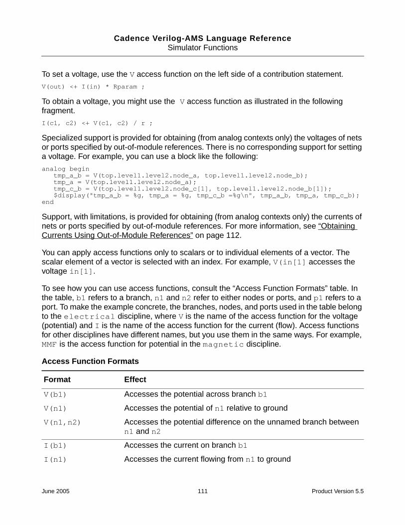
Cadence Verilog-AMS Language ReferenceSimulator Functions
To set a voltage, use the V access function on the left side of a contribution statement.
V(out) <+ I(in) * Rparam ;
To obtain a voltage, you might use the V access function as illustrated in the followingfragment.
I(c1, c2) <+ V(c1, c2) / r ;
Specialized support is provided for obtaining (from analog contexts only) the voltages of netsor ports specified by out-of-module references. There is no corresponding support for settinga voltage. For example, you can use a block like the following:
analog begintmp_a_b = V(top.level1.level2.node_a, top.level1.level2.node_b);tmp_a = V(top.level1.level2.node_a);tmp_c_b = V(top.level1.level2.node_c[1], top.level1.level2.node_b[1]);$display("tmp_a_b = %g, tmp_a = %g, tmp_c_b =%g\n", tmp_a_b, tmp_a, tmp_c_b);
end
Support, with limitations, is provided for obtaining (from analog contexts only) the currents ofnets or ports specified by out-of-module references. For more information, see “ObtainingCurrents Using Out-of-Module References” on page 112.
You can apply access functions only to scalars or to individual elements of a vector. Thescalar element of a vector is selected with an index. For example, V(in[1] accesses thevoltage in[1].
To see how you can use access functions, consult the “Access Function Formats” table. Inthe table, b1 refers to a branch, n1 and n2 refer to either nodes or ports, and p1 refers to aport. To make the example concrete, the branches, nodes, and ports used in the table belongto the electrical discipline, where V is the name of the access function for the voltage(potential) and I is the name of the access function for the current (flow). Access functionsfor other disciplines have different names, but you use them in the same ways. For example,MMF is the access function for potential in the magnetic discipline.
Access Function Formats
Format Effect
V(b1) Accesses the potential across branch b1
V(n1) Accesses the potential of n1 relative to ground
V(n1,n2) Accesses the potential difference on the unnamed branch betweenn1 and n2
I(b1) Accesses the current on branch b1
I(n1) Accesses the current flowing from n1 to ground
June 2005 111 Product Version 5.5

Cadence Verilog-AMS Language ReferenceSimulator Functions
Notice the use of the port access operator (<>) in the last format. The port identifier used ina port access function must be a scalar or resolve to a constant node of a bus port accessedby a constant expression. You cannot use the port access operator to access potential, norcan you use the port access operator on the left side of a contribution operator. The portaccess operator can be used only in modules that do not instantiate sub-hierarchies orprimitives.
You can use a port access to monitor the flow. In the following example, the simulator issuesa warning if the total diode current becomes too large.
module diode (a, c) ;electrical a, c ;branch (a, c) diode, cap ;parameter real is=1e-14, tf=0, cjo=0, imax=1, phi=0.7 ;
analog beginI(diode) <+ is*(limexp(V(diode)/$vt) -1) ;I(cap) <+ ddt(tf*I(diode) - 2 * cjo * sqrt(phi * (phi * V(cap)))) ;if (I(<a>) > imax) // Checks current through port
$strobe( "Warning: diode is melting!" ) ;end
endmodule
Obtaining Currents Using Out-of-Module References
Use the Cadence-provided system task $cds_iprobe to return the current of an out-of-module port.
OOM_current_reference ::=$cds_iprobe("hierarchical_name")
hierarchical_name is the hierarchical name of the out-of-module scalar port orindividual bit of a vector port whose current you want to access.
The $cds_iprobe task is subject to the following limitations:
■ The returned value is always the value at the last accepted simulation point. The valueremains constant until the next simulation point is accepted. As a consequence, youcannot use the $cds_iprobe task to model a source for a current controlled device.
■ The $cds_iprobe task can be used only in analog contexts.
I(n1, n2) Accesses the current flowing on the unnamed branch between n1and n2; node n1 and node n2 cannot be the same node
I(<p1>) Accesses the current flow into the module through port p1.
Access Function Formats, continued
Format Effect
June 2005 112 Product Version 5.5

Cadence Verilog-AMS Language ReferenceSimulator Functions
■ The $cds_iprobe task can be used only when the Spectre solver is active. This taskcannot be used with the UltraSim solver, nor with the ncelab -amsfastspice option.
■ You must have an active Tcl current probe set up to probe the current that the$cds_iprobe task returns.
For example, you set up a Tcl probe with the following command.
ncsim> probe -create -flow -shm -port top.I1
You create and simulate the following modules:
module top;electrical a, gnd;ground gnd;real x;vsource #(.type("sine"), .ampl(11), .freq(1k)) V1(a,gnd);leaf l1(a,gnd);analog begin
// The top.I1.a below is an out-of-module reference. $display("I<top.l1.a>=%g\n", $cds_iprobe("top.l1.a"));
endendmodule
module leaf(a,b);electrical a, b;resistor #(.r(1.0)) r1(a,b);
Endmodule
The $display statement in the analog block displays the current of port a in the instance ofthe leaf module.
Accessing Attributes
Use the hierarchical referencing operator to access the attributes for a node or branch.
attribute_reference ::=node_identifier.pot_or_flow.attribute_identifier
pot_or_flow ::=potential
| flow
node_identifier is the node or branch whose attribute you want to access.
attribute_identifier is the attribute you want to access.
For example, the following fragment illustrates how to access the abstol values for a node anda branch.
electrical a, b, n1, n2;branch (n1, n2) cap ;parameter real c= 1p;analog begin
I(a,b) <+ c*ddt(V(a,b), a.potential.abstol) ; // Access abstol for node
June 2005 113 Product Version 5.5

Cadence Verilog-AMS Language ReferenceSimulator Functions
I(cap) <+ c*ddt(V(cap), n1.potential.abstol) ; // Access abstol for branchend
Examining Drivers
A driver of a signal is one of the following:
■ A process that assigns a value to the signal
■ A connection of the signal to an output port of a module instance or simulation primitive
Each driver can have both a present value and a pending value. The present value is thepresent contribution of the driver to the signal. The pending value is the next scheduledcontribution, if any, of the driver to the signal.
The drivers associated with a signal are numbered from zero to one less than the number ofdrivers. For example, if there are five associated drivers, then they have the numbers 0, 1, 2,3, and 4.
The next sections describe the Verilog-AMS driver access functions you can use to createconnect modules that are controlled by the digital drivers in ordinary modules. Note that
■ Driver access functions (including the driver_update event keyword) can be usedonly in the digital behavioral blocks of connect modules. They cannot be used in ordinarymodules.
■ Driver access functions (including the driver_update event keyword) are sensitive todrivers of only ordinary modules
■ . These functions automatically ignore any drivers found inside connect modules.
Counting the Number of Drivers
Use the driver_count function to determine how many drivers are associated with aspecified digital signal.
driver_count_function ::=$driver_count ( signal )
signal is the name of the digital signal.
The driver_count function returns an integer, which is the number of drivers associatedwith signal.
June 2005 114 Product Version 5.5

Cadence Verilog-AMS Language ReferenceSimulator Functions
Determining the Value Contribution of a Driver
Use the driver_state function to determine the present value contribution of a specifieddriver to a specified signal.
driver_state_function ::=$driver_state ( signal , driver_index )
signal is the name of the digital signal.
driver_index is an integer number between 0 and N-1 where N is the total number ofdrivers contributing to the signal value.
The driver_state function returns one of the following state values: 0, 1, x, or z.
Determining the Strength of a Driver
Use the driver_strength function to determine the strength contribution of a specifieddriver to a specified signal.
driver_strength_function ::=$driver_strength ( signal , driver_index )
signal is the name of the digital signal.
driver_index is an integer number between 0 and N-1 where N is the total number ofdrivers contributing to the signal value.
The driver_strength function returns two strengths: bits 5 through 3 for strength0 andbits 2 through 0 for strength1.
If the value returned is 0 or 1, strength0 returns the high end of the strength range andstrength1 returns the low end of the strength range. Otherwise, the strengths of bothstrength0 and strength1 are defined as shown below.
strength0 strength1
Bits 7
Su0
6
St0
5
Pu0
4
La0
3
We0
2
Me0
1
Sm0
0
HiZ0
0
HiZ1
1
Sm1
2
Me1
3
We1
4
La1
5
Pu1
6
St1
7
Su1
Bits
B5 1 1 1 1 0 0 0 0 0 0 0 0 1 1 1 1 B2
B4 1 1 0 0 1 1 0 0 0 0 1 1 0 0 1 1 B1
B3 1 0 1 0 1 0 1 0 0 1 0 1 0 1 0 1 B0
June 2005 115 Product Version 5.5
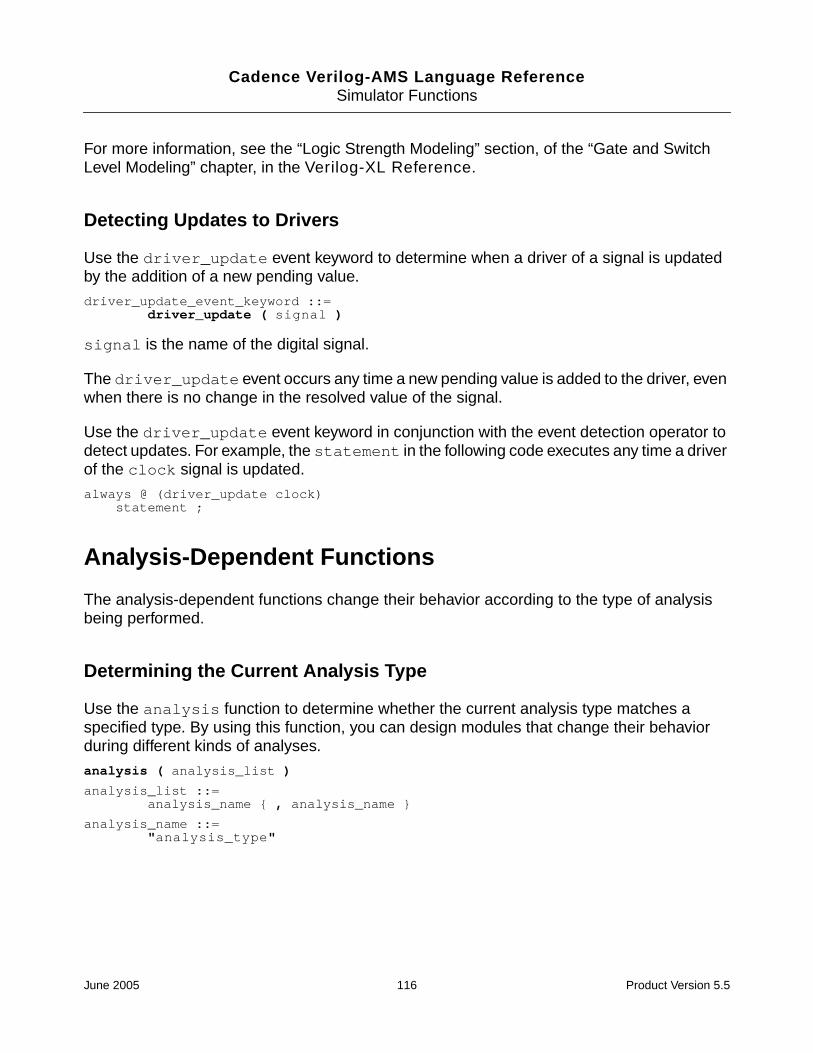
Cadence Verilog-AMS Language ReferenceSimulator Functions
For more information, see the “Logic Strength Modeling” section, of the “Gate and SwitchLevel Modeling” chapter, in the Verilog-XL Reference.
Detecting Updates to Drivers
Use the driver_update event keyword to determine when a driver of a signal is updatedby the addition of a new pending value.
driver_update_event_keyword ::=driver_update ( signal )
signal is the name of the digital signal.
The driver_update event occurs any time a new pending value is added to the driver, evenwhen there is no change in the resolved value of the signal.
Use the driver_update event keyword in conjunction with the event detection operator todetect updates. For example, the statement in the following code executes any time a driverof the clock signal is updated.
always @ (driver_update clock)statement ;
Analysis-Dependent Functions
The analysis-dependent functions change their behavior according to the type of analysisbeing performed.
Determining the Current Analysis Type
Use the analysis function to determine whether the current analysis type matches aspecified type. By using this function, you can design modules that change their behaviorduring different kinds of analyses.
analysis ( analysis_list )
analysis_list ::=analysis_name { , analysis_name }
analysis_name ::="analysis_type"
June 2005 116 Product Version 5.5
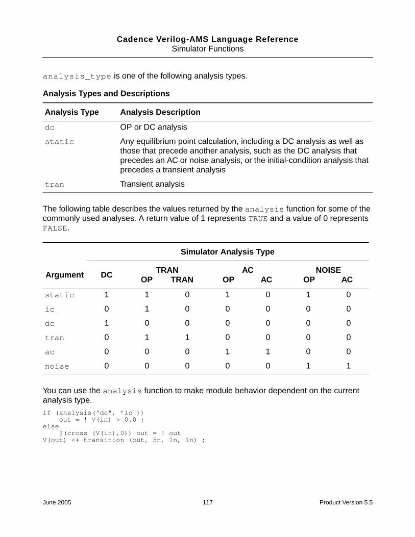
Cadence Verilog-AMS Language ReferenceSimulator Functions
analysis_type is one of the following analysis types.
The following table describes the values returned by the analysis function for some of thecommonly used analyses. A return value of 1 represents TRUE and a value of 0 representsFALSE.
You can use the analysis function to make module behavior dependent on the currentanalysis type.
if (analysis("dc", "ic"))out = ! V(in) > 0.0 ;
else@(cross (V(in),0)) out = ! out
V(out) <+ transition (out, 5n, 1n, 1n) ;
Analysis Types and Descriptions
Analysis Type Analysis Description
dc OP or DC analysis
static Any equilibrium point calculation, including a DC analysis as well asthose that precede another analysis, such as the DC analysis thatprecedes an AC or noise analysis, or the initial-condition analysis thatprecedes a transient analysis
tran Transient analysis
Simulator Analysis Type
Argument DC TRANOP TRAN
ACOP AC
NOISEOP AC
static 1 1 0 1 0 1 0
ic 0 1 0 0 0 0 0
dc 1 0 0 0 0 0 0
tran 0 1 1 0 0 0 0
ac 0 0 0 1 1 0 0
noise 0 0 0 0 0 1 1
June 2005 117 Product Version 5.5
Cadence Verilog-AMS Language ReferenceSimulator Functions
Implementing Small-Signal AC Sources
Use the ac_stim function to implement a sinusoidal stimulus for small-signal analysis.
Note: In this release of Verilog-A, the ac_stim function has no effect.
ac_stim ( [ "analysis_type" [ , mag [ , phase]]] )
analysis_type, if you specify it, must be one of the analysis types listed in the AnalysisTypes and Descriptions table on page 117. The default for analysis_type is ac. The magargument is the magnitude, with a default of 1. phase is the phase in radians, with a defaultof 0.
The ac_stim function models a source with magnitude mag and phase phase only duringthe analysis_type analysis. During all other small-signal analyses, and during large-signal analyses, the ac_stim function returns 0.
Implementing Small-Signal Noise Sources
Verilog-A provides three functions to support noise modeling during small-signal analyses:
■ white_noise function
■ flicker_noise function
■ noise_table function
Note: In this release of Verilog-A, the white_noise, flicker_noise, and noise_tablefunctions have no effect.
White_noise Function
Use the white_noise function to generate white noise, noise whose current value iscompletely uncorrelated with any previous or future values.
white_noise( PSD [ , "name"])
PSD is the power spectral density of the source where PSD is specified in units of A2/Hz orV2/Hz.
name is a label for the noise source. The simulator uses name to identify the contributions ofnoise sources to the total output noise. The simulator combines into a single source all noisesources with the same name from the same module instance.
The white_noise function is active only during small-signal noise analyses and returns 0otherwise.
June 2005 118 Product Version 5.5

Cadence Verilog-AMS Language ReferenceSimulator Functions
For example, you might include the following fragment in a module describing the behavior ofa diode.
I(diode) <+ white_noise(2 * ‘P_Q * Id, "shot" ) ;
For a resistor, you might use a fragment like the following.
V(res) <+ white_noise(4 * ‘P_K * $temperature * rs, "thermal");
flicker_noise Function
Use the flicker_noise function to generate pink noise that varies in proportion to:
The syntax for the flicker_noise function is
flicker_noise( power, exp [ , "name"])
power is the power of the source at 1 Hz.
name is a label for the noise source. The simulator uses name to identify the contributions ofnoise sources to the total output noise. The simulator combines into a single source all noisesources with the same name from the same module instance.
The flicker_noise function is active only during small-signal noise analyses and returns0 otherwise.
For example, you might include the following fragment in a module describing the behavior ofa diode:
I(diode) <+ flicker_noise( kf * pow(abs(I(diode)),af),ef) ;
Noise_table Function
Use the noise_table function to generate noise where the spectral density of the noisevaries as a piecewise linear function of frequency.
noise_table(vector [ , "name" ])
vector is an array containing pairs of real numbers. The first number in each pair is afrequency in hertz; the second number is the power at that frequency. The noise_tablefunction uses linear interpolation to compute the spectral density for each frequency. Atfrequencies lower than the lowest frequency specified in the table, the associated power isassumed to be the power associated with the lowest specified frequency. Similarly, atfrequencies higher than the highest frequency specified in the table, the associated power isassumed to be the power associated with the highest specified frequency.
1 fexp⁄
June 2005 119 Product Version 5.5

Cadence Verilog-AMS Language ReferenceSimulator Functions
name is a label for the noise source. The simulator uses name to identify the contributions ofnoise sources to the total output noise. The simulator combines into a single source all noisesources with the same name from the same module instance.
The noise_table function is active only during small-signal noise analyses and returns 0otherwise.
For example, you might include the following fragment in an analog block:
V(p,n) <+ noise_table({1,2,100,4,1000,5,1000000,6}, "noitab");
In this example, the power at every frequency lower than 1 is assumed to be 2; the power atevery frequency above 1000000 is assumed to be 6.
Generating Random Numbers
Use the $random function to generate a signed integer, 32-bit, pseudorandom number.
$random [ ( seed ) ] ;
seed is a reg, integer, or time variable used to initialize the function. The seed provides astarting point for the number sequence and allows you to restart at the same point. If, asCadence recommends, you use seed, you must assign a value to the variable before callingthe $random function.
The $random function generates a new number every time step.
Individual $random statements with different seeds generate different sequences, andindividual $random statements with the same seed generate identical sequences.
The following code fragment uses the absolute value function and the modulus operator togenerate integers between 0 and 99.
// There is a 5% chance of signal loss.module randloss (pinout) ;electrical pinout ;integer randseed, randnum;
analog begin@ (initial_step) begin
randseed = 123 ; // Initialize the seed just onceendrandnum = abs($random(randseed) % 100) ;if (randnum < 5)
V(pinout) <+ 0.0 ;else
V(pinout) <+ 3.0 ;end // of analog block
endmodule
June 2005 120 Product Version 5.5

Cadence Verilog-AMS Language ReferenceSimulator Functions
Generating Random Numbers in Specified Distributions
Verilog-A provides functions that generate random numbers in the following distributionpatterns:
■ Uniform
■ Normal (Gaussian)
■ Exponential
■ Poisson
■ Chi-square
■ Student’s T
■ Erlang
In releases prior to IC5.0, the functions beginning with $dist return real numbers rather thaninteger numbers. If you need to continue getting real numbers in more recent releases,change each $dist function to the corresponding $rdist function.
Uniform Distribution
Use the $rdist_uniform function to generate random real numbers (or the$dist_uniform function to generate integer numbers) that are evenly distributedthroughout a specified range. The $rdist_uniform function is not supported in digitalcontexts.
$rdist_uniform ( seed , start , end ) ;$dist_uniform ( seed , start , end ) ;
seed is a scalar integer variable used to initialize the sequence of generated numbers. seedmust be a variable because the function updates the value of seed at each iteration. Toensure generation of a uniform distribution, change the value of seed only when you initializethe sequence.
start is an integer or real expression that specifies the smallest number that the$dist_uniform function is allowed to return. start must be smaller than end.
end is an integer or real expression that specifies the largest number that the$dist_uniform function is allowed to return. end must be larger than start.
The following module returns a series of real numbers, each of which is between 20 and 60inclusively.
June 2005 121 Product Version 5.5

Cadence Verilog-AMS Language ReferenceSimulator Functions
module distcheck (pinout) ;electrical pinout ;parameter integer start_range = 20 ; // A parameterinteger seed, end_range;real rrandnum ;
analog begin@ (initial_step) begin
seed = 23 ; // Initialize the seed just onceend_range = 60 ; // A variable
endrrandnum = $rdist_uniform(seed, start_range, end_range);$display ("Random number is %g", rrandnum ) ;
// The next line shows how the seed changes at each// iterative use of the distribution function.
$display ("Current seed is %d", seed) ;
V(pinout) <+ rrandnum ;end // of analog block
endmodule
Normal (Gaussian) Distribution
Use the $rdist_normal function to generate random real numbers (or the $dist_normalfunction to generate integer numbers) that are normally distributed. The $rdist_normalfunction is not supported in digital contexts.
$rdist_normal ( seed , mean , standard_deviation ) ;$dist_normal ( seed , mean , standard_deviation ) ;
seed is a scalar integer variable used to initialize the sequence of generated numbers. seedmust be a variable because the function updates the value of seed at each iteration. Toensure generation of a normal distribution, change the value of seed only when you initializethe sequence.
mean is an integer or real expression that specifies the value to be approached by the meanvalue of the generated numbers.
standard_deviation is an integer or real expression that determines the width ofspread of the generated values around mean. Using a larger standard_deviationspreads the generated values over a wider range.
To generate a gaussian distribution, use a mean of 0 and a standard_deviation of 1.For example, the following module returns a series of real numbers that together form agaussian distribution.
module distcheck (pinout) ;electrical pinout ;integer seed ;real rrandnum ;
analog begin@ (initial_step) begin
June 2005 122 Product Version 5.5

Cadence Verilog-AMS Language ReferenceSimulator Functions
seed = 23 ;endrrandnum = $rdist_normal( seed, 0, 1 ) ;$display ("Random number is %g", rrandnum ) ;V(pinout) <+ rrandnum ;
end // of analog block
endmodule
Exponential Distribution
Use the $rdist_exponential function to generate random real numbers (or the$dist_exponential function to generate integer numbers) that are exponentiallydistributed. The $rdist_exponential function is not supported in digital contexts.
$rdist_exponential ( seed , mean ) ;$dist_exponential ( seed , mean ) ;
seed is a scalar integer variable used to initialize the sequence of generated numbers. seedmust be a variable because the function updates the value of seed at each iteration. Toensure generation of an exponential distribution, change the value of seed only when youinitialize the sequence.
mean is an integer or real value greater than zero. mean specifies the value to be approachedby the mean value of the generated numbers.
For example, the following module returns a series of real numbers that together form anexponential distribution.
module distcheck (pinout) ;electrical pinout ;integer seed, mean ;real rrandnum ;
analog begin@ (initial_step) begin
seed = 23 ;mean = 5 ; // Mean must be > 0
endrrandnum = $rdist_exponential(seed, mean) ;$display ("Random number is %g", rrandnum ) ;V(pinout) <+ rrandnum ;
end // of analog block
endmodule
Poisson Distribution
Use the $rdist_poisson function to generate random real numbers (or the$dist_poisson function to generate integer numbers) that form a Poisson distribution. The$rdist_poisson function is not supported in digital contexts.
June 2005 123 Product Version 5.5

Cadence Verilog-AMS Language ReferenceSimulator Functions
$rdist_poisson ( seed , mean ) ;$dist_poisson ( seed , mean ) ;
seed is a scalar integer variable used to initialize the sequence of generated numbers. seedmust be a variable because the function updates the value of seed at each iteration. Toensure generation of a Poisson distribution, change the value of seed only when youinitialize the sequence.
mean is an integer or real value greater than zero. mean specifies the value to be approachedby the mean value of the generated numbers.
For example, the following module returns a series of real numbers that together form aPoisson distribution.
module distcheck (pinout) ;electrical pinout ;integer seed, mean ;real rrandnum ;
analog begin@ (initial_step) begin
seed = 23 ;mean = 5 ; // Mean must be > 0
endrrandnum = $rdist_poisson(seed, mean) ;$display ("Random number is %g", rrandnum ) ;V(pinout) <+ rrandnum ;
end // of analog block
endmodule
Chi-Square Distribution
Use the $rdist_chi_square function to generate random real numbers (or the$dist_chi_square function to generate integer numbers) that form a chi-squaredistribution. The $rdist_chi_square function is not supported in digital contexts.
$rdist_chi_square ( seed , degree_of_freedom ) ;$dist_chi_square ( seed , degree_of_freedom ) ;
seed is a scalar integer variable used to initialize the sequence of generated numbers. seedmust be a variable because the function updates the value of seed at each iteration. Toensure generation of a chi-square distribution, change the value of seed only when youinitialize the sequence.
degree_of_freedom is an integer value greater than zero. degree_of_freedomdetermines the width of spread of the generated values. Using a largerdegree_of_freedom spreads the generated values over a wider range.
For example, the following module returns a series of real numbers that together form achi-square distribution.
June 2005 124 Product Version 5.5

Cadence Verilog-AMS Language ReferenceSimulator Functions
module distcheck (pinout) ;electrical pinout ;integer seed, dof ;real rrandnum ;
analog begin@ (initial_step) begin
seed = 23 ;dof = 5 ; // Degree of freedom must be > 0
endrrandnum = $rdist_chi_square(seed, dof) ;$display ("Random number is %g", rrandnum ) ;V(pinout) <+ rrandnum ;
end // of analog block
endmodule
Student’s T Distribution
Use the $rdist_t function to generate random real numbers (or the $dist_t function togenerate integer numbers) that form a Student’s T distribution. The $rdist_t function is notsupported in digital contexts.
$rdist_t ( seed , degree_of_freedom ) ;$dist_t ( seed , degree_of_freedom ) ;
seed is a scalar integer variable used to initialize the sequence of generated numbers. seedmust be a variable because the function updates the value of seed at each iteration. Toensure generation of a Student’s T distribution, change the value of seed only when youinitialize the sequence.
degree_of_freedom is an integer value greater than zero. degree_of_freedomdetermines the width of spread of the generated values. Using a largerdegree_of_freedom spreads the generated values over a wider range.
For example, the following module returns a series of real numbers that together form aStudent’s T distribution.
module distcheck (pinout) ;electrical pinout ;integer seed, dof ;real rrandnum ;
analog begin@ (initial_step) begin
seed = 23 ;dof = 15 ; // Degree of freedom must be > 0
endrrandnum = $rdist_t(seed, dof) ;$display ("Random number is %g", rrandnum ) ;V(pinout) <+ rrandnum ;
end // of analog block
endmodule
June 2005 125 Product Version 5.5

Cadence Verilog-AMS Language ReferenceSimulator Functions
Erlang Distribution
Use the $rdist_erlang function to generate random real numbers (or the $dist_erlangfunction to generate integer numbers) that form an Erlang distribution. The $rdist_erlangfunction is not supported in digital contexts.
$rdist_erlang ( seed , k , mean ) ;$dist_erlang ( seed , k , mean ) ;
seed is a scalar integer variable used to initialize the sequence of generated numbers. seedmust be a variable because the function updates the value of seed at each iteration. Toensure generation of an Erlang distribution, change the value of seed only when you initializethe sequence.
k is an integer value greater than zero. Using a larger value for k decreases the variance ofthe distribution.
mean is an integer or real value greater than zero. mean specifies the value to be approachedby the mean value of the generated numbers.
For example, the following module returns a series of real numbers that together form anErlang distribution.
module distcheck (pinout) ;electrical pinout ;integer seed, k, mean ;real rrandnum ;
analog begin@ (initial_step) begin
seed = 23 ;k = 20 ; // k must be > 0mean = 15 ; // Mean must be > 0
endrrandnum = $rdist_erlang(seed, k, mean) ;$display ("Random number is %g", rrandnum ) ;V(pinout) <+ rrandnum ;
end // of analog block
endmodule
Determining Whether a Parameter Value is Overridden
Use the $param_given function to determine whether a parameter value is obtained fromthe default value in its declaration statement or from an override. The function returns 1 if thedefault parameter value is overridden by either a defparam statement or by a moduleinstance parameter value assignment. The function returns 0 otherwise.
$param_given ( module_parameter_identifier )
module_parameter_identifier is parameter identifier.
June 2005 126 Product Version 5.5

Cadence Verilog-AMS Language ReferenceSimulator Functions
For example, the fragment
if($param_given(tdevice))temp = tdevice + ‘P_CELSIUS0 ;
elsetemp = $temperature ;
sets temp to the ambient temperature of the circuit (whatever that might be) when the defaultvalue of tdevice is not overridden. The fragment sets temp to a value calculated from thetdevice value when the tdevice value is set by an override.
Interpolating with Table Models
Use the $table_model function to model the behavior of a design by interpolating betweenand extrapolating outside of data points.
table_model_declaration ::=$table_model(variables , data_file [ , ctrl_string ] )
variables ::=independent_var { , independent_var }
data_file ::="filename"
ctrl_string ::="sub_ctrl_string { , sub_ctrl_string }"
sub_ctrl_string ::=[ degree_char ] [ extrap_char [ extrap_char ]]
degree_char ::=1 | 2 | 3
extrap_char ::=C | L | S | E
independent_var is a numerical expression used as an independent model variable. Itcan be any legal expression that can be assigned to an analog signal.
filename is the text file that stores the sample points. For more information, see “TableModel File Format” on page 128.
ctrl_string controls the numerical aspects of the interpolation process. It consists ofsubcontrol strings for each dimension.
degree_char is the degree of the splines used for interpolation. The degree must not bezero or exceed 3. The default value is 1.
extrap_char controls how the simulator evaluates a point that is outside the region ofsample points included in the data file. The C (clamp) extrapolation method uses a horizontalline that passes through the nearest sample point, also called the end point, to extend themodel evaluation. The L (linear) extrapolation method, which is the default method, models
June 2005 127 Product Version 5.5

Cadence Verilog-AMS Language ReferenceSimulator Functions
the extrapolation through a tangent line at the end point. The S (spline) extrapolation methoduses the polynomial for the nearest segment (the segment at the end) to evaluate a pointbeyond the interpolation area. The E (error) extrapolation method ends the simulation whenthe point to be evaluated is beyond the interpolation area.
You can specify the extrapolation method to be used for each end of the sample point region.When you do not specify an extrap_char value, the linear extrapolation method is used forboth ends. When you specify only one extrap_char value, the specified extrapolationmethod is used for both ends. When you specify two extrap_char values, the first characterspecifies the extrapolation method for the end with the smaller coordinate value, and thesecond character specifies the method for the end with the larger coordinate value.
The $table_model function is subject to the same restrictions as analog operators withrespect to where the function can be used. For more information, see “Restrictions on UsingAnalog Operators” on page 131.
Table Model File Format
The data in the table model file must be in the form of a family of ordered isolines. An isolineis a curve of at least two values generated when one variable is swept and all other variablesare held constant. An ordered isoline is an isoline in which the sweeping variable is eithermonotonically increasing or monotonically decreasing. A monotonically increasingvariable is one in which every subsequent value is equal to or greater than the previous value.A monotonically decreasing variable is one in which every subsequent value is equal to orless than the previous value.
For example, a bipolar transistor can be described by a family of isolines, where each isolineis generated by holding the base current constant and sweeping the collector voltage from 0to some maximum voltage. If the collector voltage sweeps monotonically, the generatedisoline is an ordered isoline. In this example, the collector voltage takes many values for eachof the isolines so the voltage is the fastest changing independent variable and the basecurrent is the slowest changing independent variable. You need to know the fastestchanging and slowest changing independent variables to arrange the data correctly in thetable model file.
The sample points are stored in the file in the following format:
P1P2P3...PM
June 2005 128 Product Version 5.5

Cadence Verilog-AMS Language ReferenceSimulator Functions
where Pi (i = 1...M) are the sample points. Each sample point Pi is on a separate line andis represented as a sequence of numbers, Xi1 Xi2 ... XiN Yi where N is the highestdimension of the model, Xik is the coordinate of the sample point in the kth dimension, andYi is the model value at this point. Xi1 (the leftmost variable) must be the fastest changingvariable, XiN (the rightmost variable other than the model value) must be the slowestchanging variable, and the other variables must be arranged in between from fastestchanging to slowest changing. Comments, which begin with #, can be inserted anyplace inthe file and continue to the end of the line.
For example, to create a table model with three ordered isolines representing the function
z = f(x,y) = x2+y
you build the model as follows, assuming that you want to have four sample values on eachisoline. The x values used here are all the same and equally spaced on each isoline, but theydo not have to be.
Isoline 1: y=1
x = 1, 2, 3, 4z = 1, 5, 10, 17
Isoline 2: y=2
x = 1, 2, 3, 4z = 3, 6, 11, 18
Isoline 3: y=3
x = 1, 2, 3, 4z = 4, 7, 12, 19
You enter the table model data into the file as
# x is the fastest changing independent variable.# y is the slowest changing independent variable.# z is the table model value at each point.# x y z
1 1 12 1 53 1 104 1 171 2 32 2 63 2 114 2 181 3 42 3 73 3 124 3 19
June 2005 129 Product Version 5.5

Cadence Verilog-AMS Language ReferenceSimulator Functions
Example
For example, assume that you have an appropriate data file named nmos.tbl. You mightuse it in a module as follows.
‘include "disciplines.vams"‘include "constants.vams"
module mynmos (g, d, s);electrical g, d, s;inout g, d, s;
analog beginI(d, s) <+ $table_model (V(g, s), V(d, s), "nmos.tbl", "3CL,3CL");
end
endmodule
In this example, the independent variables are V(g,s) and V(d,s). The degree of thesplines used for interpolation is 3 for each of the two dimensions. For each of the twodimensions, the extrapolation method for the lower end is clamping and the extrapolation forthe upper end is linear.
Analog Operators
Analog operators are functions that operate on more than just the current value of theirarguments. These functions maintain an internal state and produce a return value that is afunction of an input expression, the arguments, and their internal state.
The analog operators are the
■ Limited exponential function
■ Time derivative operator
■ Time integral operator
■ Circular integrator operator
■ Delay operator
■ Transition filter
■ Slew filter
■ Laplace transform filters
■ Z-transform filters
June 2005 130 Product Version 5.5

Cadence Verilog-AMS Language ReferenceSimulator Functions
Restrictions on Using Analog Operators
Analog operators are subject to these restrictions:
■ You can use analog operators inside an if or case construct only if the controllingconditional expression consists entirely of genvar expressions, literal numericalconstants, parameters,, or the analysis function.
■ You cannot use analog operators in repeat, while, or for statements.
■ You cannot use analog operators inside a function.
■ You cannot use analog operators inside initial blocks, always blocks, or user-defined functions.
■ You cannot specify a null argument in the argument list of an analog operator.
Limited Exponential Function
Use the limited exponential function to calculate the exponential of a real argument.
limexp( expr )
expr is a dynamic expression of type real.
The limexp function limits the iteration step size to improve convergence. limexp behaveslike the exp function, except that using limexp to model semiconductor junctions generallyresults in dramatically improved convergence. For information on the exp function, see“Standard Mathematical Functions” on page 92.
The limexp function is subject to the restrictions listed in “Restrictions on Using AnalogOperators” on page 131.
Time Derivative Operator
Use the time derivative operator to calculate the time derivative of an argument.
ddt( input [ , abstol | nature ] )
input is a dynamic expression.
abstol is a constant specifying the absolute tolerance that applies to the output of the ddtoperator. Set abstol at the largest signal level that you consider negligible. In this releaseof Verilog-A, abstol is ignored.
June 2005 131 Product Version 5.5

Cadence Verilog-AMS Language ReferenceSimulator Functions
nature is a nature from which the absolute tolerance is to be derived. In this release ofVerilog-A, nature is ignored.
The time derivative operator is subject to the restrictions listed in “Restrictions on UsingAnalog Operators” on page 131.
In DC analyses, the ddt operator returns 0. To define a higher order derivative, you must usean internal node or signal. For example, a statement such as the following is illegal.
V(out) <+ ddt(ddt(V(in))) // ILLEGAL!
For an example illustrating how to define higher order derivatives correctly, see “UsingIntegration and Differentiation with Analog Signals” on page 38.
Time Integral Operator
Use the time integral operator to calculate the time integral of an argument.
idt( input [ , ic [ , assert [ , abstol | nature ] ] ] )
input is a dynamic expression to be integrated.
ic is a dynamic expression specifying the initial condition.
assert is a dynamic integer-valued parameter. To reset the integration, set assert to anonzero value.
abstol is a constant explicit absolute tolerance that applies to the input of the idt operator.Set abstol at the largest signal level that you consider negligible.
nature is a nature from which the absolute tolerance is to be derived.
The time integral operator is subject to the restrictions listed in “Restrictions on Using AnalogOperators” on page 131.
The value returned by the idt operator during DC or AC analysis depends on which of theparameters you specify.
If you specify Then idt returns
input
The time-integral of x from 0 to t with the initial condition beingcomputed in the DC analysis.
x τ( ) τd0t∫
June 2005 132 Product Version 5.5

Cadence Verilog-AMS Language ReferenceSimulator Functions
The initial condition forces the DC solution to the system. You must specify the initialcondition, ic, unless you are using the idt operator in a system with feedback that forcesinput to zero. If you use a model in a feedback configuration, you can leave out the initialcondition without any unexpected behavior during simulation. For example, an operationalamplifier alone needs an initial condition, but the same amplifier with the right externalfeedback circuitry does not need that forced DC solution.
The following statement illustrates using idt with a specified initial condition.
V(out) <+ sin(2*`M_PI*(fc*$abstime + idt(gain*V(in),0))) ;
Circular Integrator Operator
Use the circular integrator operator to convert an expression argument into its indefinitelyintegrated form.
idtmod(expr [ , ic [ , modulus [, offset [, abstol | nature ] ] ] ] )
input, ic
The time-integral of x from 0 to t with initial condition ic. In DC or ICanalyses, returns ic.
input, ic,assert
The time-integral of x from t0 to t with initial condition ic. In DC or ICanalyses, and when assert is nonzero, returns ic. t0 is the timewhen assert last became 0.
input, ic,assert, abstol
The time-integral of x from t0 to t with initial condition ic. In DC or ICanalysis, and when assert is nonzero, returns ic. t0 is the timewhen assert last became 0.
input, ic,assert, nature
The time-integral of x from t0 to t with initial condition ic. In DC or ICanalysis, and when assert is nonzero, returns ic. t0 is the timewhen assert last became 0.
If you specify Then idt returns
x τ( ) τd0t∫ ic+
x τ( ) τdt0
t∫ ic+
x τ( ) τdt0
t∫ ic+
x τ( ) τdt0
t∫ ic+
June 2005 133 Product Version 5.5

Cadence Verilog-AMS Language ReferenceSimulator Functions
expr is the dynamic integrand or expression to be integrated.
ic is a dynamic initial condition. By default, the value of ic is zero.
modulus is a dynamic value at which the output of idtmod is reset. modulus must be apositive value equation. If you do not specify modulus, idtmod behaves like the idtoperator and performs no limiting on the output of the integrator.
offset is a dynamic value added to the integration. The default is zero.
The modulus and offset parameters define the bounds of the integral. The output of theidtmod function always remains in the range
offset < idtmod_output < offset+modulus
abstol is a constant explicit absolute tolerance that applies to the input of the idtmodoperator. Set abstol at the largest signal level that you consider negligible.
nature is a nature from which the absolute tolerance is to be derived.
The circular integrator operator is subject to the restrictions listed in “Restrictions on UsingAnalog Operators” on page 131.
The value returned by the idtmod operator depends on which parameters you specify.
If you specify Then idtmod returns
expr
The time-integral of expr from 0 to t with the initial condition beingcomputed in the DC analysis. Returns x.
expr, ic
The time-integral of expr from 0 to t with initial condition ic. In DCor IC analysis, returns ic; otherwise, returns x.
expr, ic,modulus
where x = n*modulus + kn = ... -3, -2, -1, 0, 1, 2, 3 ...Returns k where 0 < k < modulus
x expr τ( ) τd0t∫=
x expr τ( ) τd0t∫ ic+=
x expr τ( ) τd0t∫ ic+=
June 2005 134 Product Version 5.5

Cadence Verilog-AMS Language ReferenceSimulator Functions
The initial condition forces the DC solution to the system. You must specify the initialcondition, ic, unless you are using idtmod in a system with feedback that forces expr tozero. If you use a model in a feedback configuration, you can leave out the initial conditionwithout any unexpected behavior during simulation.
Example
The circular integrator is useful in cases where the integral can get very large, such as in avoltage controlled oscillator (VCO). For example, you might use the following approach togenerate arguments in the range [0,2π] for the sinusoid.
phase = idtmod(fc + gain*V(IN), 0, 1, 0); //Phase is in range [0,1].V(OUT) <+ sin(2*PI*phase);
Delay Operator
Use the absdelay operator to delay the entire signal of a continuously valued waveform.
absdelay( expr , time_delay [ , max_delay ] )
expr is a dynamic expression to be delayed.
time_delay, a dynamic nonnegative value, is the length of the delay. If you specifymax_delay, you can change the value of time_delay during a simulation, as long as the
expr, ic,modulus,offset
where x = n*modulus + kReturns k where offset < k < offset + modulus
expr, ic,modulus,offset,abstol where x = n*modulus + k
Returns k where offset < k < offset + modulus
expr, ic,modulus,offset,nature where x = n*modulus + k
Returns k where offset < k < offset + modulus
If you specify Then idtmod returns
x expr τ( ) τd0t∫ ic+=
x expr τ( ) τd0t∫ ic+=
x expr τ( ) τd0t∫ ic+=
June 2005 135 Product Version 5.5

Cadence Verilog-AMS Language ReferenceSimulator Functions
value remains in the range 0 < time_delay < max_delay. Typically time_delay is aconstant but can also vary with time (when max_delay is defined).
max_delay is a constant nonnegative number greater than or equal to time_delay. Youcannot change max_delay because the simulator ignores any attempted changes andcontinues to use the initial value.
For example, to delay an input voltage you might code
V(out) <+ absdelay(V(in), 5u) ;
The absdelay operator is subject to the restrictions listed in “Restrictions on Using AnalogOperators” on page 131.
In DC and operating analyses, the absdelay operator returns the value of expr unchanged.In time-domain analyses, the absdelay operator introduces a transport delay equal to theinstantaneous value of time_delay based on the following formula.
Output(t) = Input(max(t-time_delay, 0))
Transition Filter
Use the transition filter to smooth piecewise constant waveforms, such as digital logicwaveforms. The transition filter returns a real number that over time describes apiecewise linear waveform. The transition filter also causes the simulator to place timepoints at both corners of a transition to assure that each transition is adequately resolved.
transition(input [, delay [, rise_time [, fall_time [, time_tol ]]]])
input is a dynamic input expression that describes a piecewise constant waveform. It musthave a real value. In DC analysis, the transition filter simply returns the value of input.Changes in input do not have an effect on the output value until delay seconds havepassed.
delay is a dynamic nonnegative real value that is an initial delay. By default, delay has avalue of zero.
rise_time is a dynamic positive real value specifying the time over which you want positivetransitions to occur. If you do not specify rise_time or if you give rise_time a value of0, rise_time defaults to the value defined by ‘default_transition.
fall_time is a dynamic positive real number specifying the time over which you wantnegative transitions to occur. By default, fall_time has the same value that rise_timehas. If you do not specify rise_time or if you give rise_time a value of 0, fall_timedefaults to the value defined by ‘default_transition.
June 2005 136 Product Version 5.5

Cadence Verilog-AMS Language ReferenceSimulator Functions
time_tol is a constant expression with a positive value. This option requires the simulatorto place time points no more than the value of time_tol away from the two corners of thetransition.
If ‘default_transition is not specified, the default behavior of the transition filterapproximates the ideal behavior of a zero-duration transition.
The transition filter is subject to the restrictions listed in “Restrictions on Using AnalogOperators” on page 131.
With the transition filter, you can control transitions between discrete signal levels bysetting the rise time and fall time of signal transitions. The transition filter stretchesinstantaneous changes in signals over a finite amount of time, as shown below, and can alsodelay the transitions.
Use short transitions with caution because they can cause the simulator to slow down to meetaccuracy constraints.
The next code fragment demonstrates how the transition filter might be used.
// comparator modelanalog begin
if ( V(in) > 0 ) beginVout = 5 ;end
else beginVout = 0 ;
endV(out) <+ transition(Vout) ;
end
output_expr(t)expr(t)
fall_time
rise_time
delay
t0t0
June 2005 137 Product Version 5.5

Cadence Verilog-AMS Language ReferenceSimulator Functions
Caution
The transition filter is designed to smooth out piecewise constantwaveforms. If you apply the transition filter to smoothly varyingwaveforms, the simulator might run slowly, and the results will probablybe unsatisfactory. For smoothly varying waveforms, consider using theslew filter instead. For information, see “Slew Filter” on page 140.
If interrupted on a rising transition, the transition filter adjusts the slope so that at therevised end of the transition the value is that of the new destination.
In the following example, a rising transition is interrupted when it is about three fourthscomplete, and the value of the new destination is below the value at the point of interruption.The transition filter computes the slope that would complete a transition from the neworigin (not the value at the point of interruption) in the specified fall_time. The
If the new destination value is below thevalue at the point of interruption, thetransition filter
If the new destination value is above thevalue at the point of interruption, thetransition filter
1. Uses the value of the originaldestination as the value of the neworigin.
2. Adjusts the slope of the transition to therate at which the value would decayfrom the value of the new origin to thevalue of the new destination infall_time seconds.
3. Causes the value of the filter output todecay at the new slope, from the valueat the point of interruption to the valueat the new destination.
1. Retains the original origin.
2. Adjusts the slope of the transition to therate at which the value would increasefrom the value of the origin to the valueof the new destination in rise_timeseconds.
3. Causes the value of the filter output toincrease at the new slope, from thevalue at the point of interruption to thevalue at the new destination.
June 2005 138 Product Version 5.5

Cadence Verilog-AMS Language ReferenceSimulator Functions
transition filter then uses the computed slope to transition from the current value to thenew destination.
An interruption in a falling transition causes the transition filter to behave in an equivalentmanner.
With larger delays, it is possible for a new transition to be specified before a previouslyspecified transition starts. The transition filter handles this by deleting any transitions thatwould follow a newly scheduled transition. A transition filter can have an arbitrary numberof transitions pending. You can use a transition filter in this way to implement thetransport delay of discretely valued signals.
The following example implements a D-type flip flop. The transition filter smooths theoutput waveforms.
module d_ff(vin_d, vclk, vout_q, vout_qbar) ;input vclk, vin_d ;output vout_q, vout_qbar ;electrical vout_q, vout_qbar, vclk, vin_d ;parameter real vlogic_high = 5 ;parameter real vlogic_low = 0 ;parameter real vtrans_clk = 2.5 ;parameter real vtrans = 2.5 ;parameter real tdel = 3u from [0:inf) ;parameter real trise = 1u from (0:inf) ;parameter real tfall = 1u from (0:inf) ;
integer x ;
analog begin@ (cross( V(vclk) - vtrans_clk, +1 )) x = (V(vin_d) > vtrans) ;V(vout_q) <+ transition( vlogic_high*x + vlogic_low*!x,tdel, trise, tfall );V(vout_qbar) <+ transition( vlogic_high*!x + vlogic_low*x, tdel,
trise, tfall ) ;end
endmodule
The following example illustrates a use of the transition filter that should be avoided. Theexpression is dependent on a continuous signal and, as a consequence, the filter runs slowly.
I(p, n) <+ transition(V(p, n)/out1, tdel, trise, tfall); // Do not do this.
Original destination
New destination
Interruption
output_expression(t)
New origin
rise_time
fall_time
June 2005 139 Product Version 5.5

Cadence Verilog-AMS Language ReferenceSimulator Functions
However, you can use the following approach to implement the same behavior in a statementthat runs much faster.
I(p, n) <+ V(p, n) * transition(1/out1, tdel, trise, tfall); // Do this instead.
Slew Filter
Use the slew filter to control the rate of change of a waveform. A typical use for slew isgenerating continuous signals from piecewise continuous signals. For discrete signals,consider using the transition filter instead. See “Transition Filter” on page 136 for moreinformation.
slew(input [ , max_pos_rate [ , max_neg_rate ] ] )
input is a dynamic expression with a real value. In DC analysis, the slew filter simplyreturns the value of input.
max_pos_rate is a dynamic real number greater than zero, which is the maximum positiveslew rate.
max_neg_rate is a dynamic real number less than zero, which is the maximum negativeslew rate.
If you specify only one rate, its absolute value is used for both rates. If you give no rates, slewpasses the signal through unchanged. If the rate of change of input is less than thespecified maximum slew rates, slew returns the value of input.
The slew filter is subject to the restrictions listed in “Restrictions on Using Analog Operators”on page 131.
When applied, slew forces all transitions of expr faster than max_pos_rate to change atthe max_pos_rate rate for positive transitions and limits negative transitions to themax_neg_rate rate.
The slew filter is particularly valuable for controlling the rate of change of sinusoidalwaveforms. The transition function distorts such signals, whereas slew preserves thegeneral shape of the waveform. The following 4-bit digital-to-analog converter uses the slewfunction to control the rate of change of the analog signal at its output.
∆y
∆t
output_expression(t)y∆t∆
------ max_pos_rate≤
June 2005 140 Product Version 5.5

Cadence Verilog-AMS Language ReferenceSimulator Functions
module dac4(d, out) ;input [0:3] d ;inout out ;electrical [0:3] d ;electrical out ;parameter real slewrate = 0.1e6 from (0:inf) ;
real Ti ;real Vref ;real scale_fact ;
analog beginTi = 0 ;Vref = 1.0 ;scale_fact = 2 ;generate ii (3,0,-1) begin
Ti = Ti + ((V(d[ii]) > 2.5) ? (1.0/scale_fact) : 0);scale_fact = scale_fact/2 ;
endV(out) <+ slew( Ti*Vref, slewrate ) ;
endendmodule
Implementing Laplace Transform S-Domain Filters
The Laplace transform filters implement lumped linear continuous-time filters. Each filteraccepts an optional absolute tolerance parameter ε, which this release of Verilog-A ignores.The set of array values that are used to define the poles and zeros, or numerator anddenominator, of a filter the first time it is used during an analysis are used at all subsequenttime points of the analysis. As a result, changing array values during an analysis has no effecton the filter.
The Laplace transform filters are subject to the restrictions listed in “Restrictions on UsingAnalog Operators” on page 131. However, while most analog functions can be used, withcertain restrictions, in if or case constructs, the Laplace transform filters cannot be used inif or case constructs in any circumstances.
Numerator Order Determination
The highest order coefficient of the numerator in Laplace filters must not be zero. To helpavoid this error, the order of the numerator coefficient in Laplace filters is automaticallyreduced so that the high order coefficient is non-zero. (Unless the coefficient consists only ofzeros, which is an error.)
Arguments Represented as Vectors
If you use an argument represented as a vector to define a numerator in a Laplace filter, andif one or more of the elements in the vector are 0, the order of the numerator is determined
June 2005 141 Product Version 5.5

Cadence Verilog-AMS Language ReferenceSimulator Functions
by the position of the rightmost non-zero vector element. For example, in the followingmodule, the order of the numerator, nn, is 1
module test(pin, nin, pout, nout);electrical pin, nin, pout, nout;
real nn[0:2];real dd[0:2];
analog begin@(initial_step) begin
nn[0] = 1;// The highest order non-zero coefficient of the numerator.nn[1] = 0;nn[2] = 0;dd[0] = 1;dd[1] = 1;dd[2] = 1;
endV(pout, nout) <+ laplace_nd(V(pin,nin), nn, dd);
endendmodule
Arguments Represented as Arrays
If you use an argument represented as an array constant to define a numerator in a Laplacefilter, and if one or more of the elements in the array constant are 0, the order of the numeratoris determined by the position of the rightmost non-zero array element. For example, if yournumerator array constant is {1,0,0}, the order of the numerator is 1. If your array constant is{1,0,1}, the order of the numerator is 3. In the following example, the numerator order is 1 (andthe value is 1).
module test(pin, nin, pout, nout);electrical pin, nin, pout, nout;
analog beginV(pout, nout) <+ laplace_nd(V(pin,nin), {1,0,0}, {1,1,1});
endendmodule
Zero-Pole Laplace Transforms
Use laplace_zp to implement the zero-pole form of the Laplace transform filter.
laplace_zp(expr, ζ, ρ [ , ε ])
ζ (zeta) is a fixed-sized vector of M pairs of real numbers. Each pair represents a zero. Thefirst number in the pair is the real part of the zero, and the second is the imaginary part. ρ(rho) is a fixed-sized vector of N real pairs, one for each pole. Specify the poles in the samemanner as the zeros. If you use array literals to define the ζ and ρ vectors, the values mustbe constant or dependent upon parameters only. You cannot use array literal values definedby variables.
The transfer function is
June 2005 142 Product Version 5.5
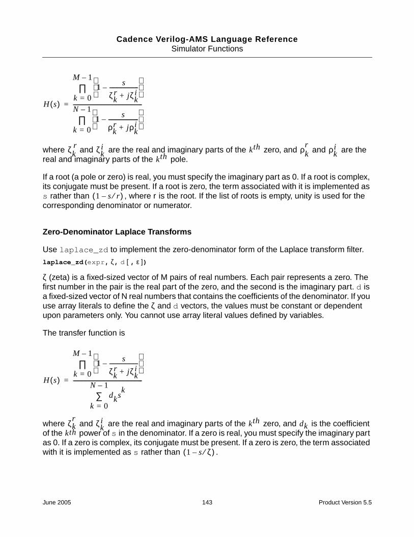
Cadence Verilog-AMS Language ReferenceSimulator Functions
where and are the real and imaginary parts of the zero, and and are thereal and imaginary parts of the pole.
If a root (a pole or zero) is real, you must specify the imaginary part as 0. If a root is complex,its conjugate must be present. If a root is zero, the term associated with it is implemented ass rather than , where r is the root. If the list of roots is empty, unity is used for thecorresponding denominator or numerator.
Zero-Denominator Laplace Transforms
Use laplace_zd to implement the zero-denominator form of the Laplace transform filter.
laplace_zd(expr, ζ, d [ , ε ])
ζ (zeta) is a fixed-sized vector of M pairs of real numbers. Each pair represents a zero. Thefirst number in the pair is the real part of the zero, and the second is the imaginary part. d isa fixed-sized vector of N real numbers that contains the coefficients of the denominator. If youuse array literals to define the ζ and d vectors, the values must be constant or dependentupon parameters only. You cannot use array literal values defined by variables.
The transfer function is
where and are the real and imaginary parts of the zero, and is the coefficientof the power of s in the denominator. If a zero is real, you must specify the imaginary partas 0. If a zero is complex, its conjugate must be present. If a zero is zero, the term associatedwith it is implemented as s rather than .
H s( )
1 s
ζkr jζk
i+---------------------–
k 0=
M 1–∏
1 s
ρkr jρk
i+----------------------–
k 0=
N 1–∏
---------------------------------------------------=
ζkr ζk
i kth ρkr ρk
i
kth
1 s r⁄–( )
H s( )
1 s
ζkr jζk
i+---------------------–
k 0=
M 1–∏
dksk
k 0=
N 1–∑
---------------------------------------------------=
ζkr ζk
i kth dkkth
1 s ζ⁄–( )
June 2005 143 Product Version 5.5

Cadence Verilog-AMS Language ReferenceSimulator Functions
Numerator-Pole Laplace Transforms
Use laplace_np to implement the numerator-pole form of the Laplace transform filter.
laplace_np(expr, n, ρ [ , ε ])
n is a fixed-sized vector of M real numbers that contains the coefficients of the numerator. ρ(rho) is a fixed-sized vector of N pairs of real numbers. Each pair represents a pole. The firstnumber in the pair is the real part of the pole, and the second is the imaginary part. If you usearray literals to define the n and ρ vectors, the array values must be constant or dependentupon parameters only. You cannot use array values defined by variables.
The transfer function is
where is the coefficient of the power of s in the numerator, and and are thereal and imaginary parts of the pole. If a pole is real, you must specify the imaginary partas 0. If a pole is complex, its conjugate must be present. If a pole is zero, the term associatedwith it is implemented as s rather than .
Numerator-Denominator Laplace Transforms
Use laplace_nd to implement the numerator-denominator form of the Laplace transformfilter.
laplace_nd(expr, n, d [ , ε ])
n is a fixed-sized vector of M real numbers that contains the coefficients of the numerator, andd is a fixed-sized vector of N real numbers that contains the coefficients of the denominator.If you use array literals to define the n and d vectors, the values must be constant ordependent upon parameters only. You cannot use array values defined by variables.
The transfer function is
H s( )
nksk
k 0=
M 1–∑
1 s
ρkr jρk
i+----------------------–
k 0=
N 1–∏
---------------------------------------------------=
nk kth ρkr ρk
i
kth
1 s ρ⁄–( )
June 2005 144 Product Version 5.5

Cadence Verilog-AMS Language ReferenceSimulator Functions
where is the coefficient of the power of s in the numerator, and is the coefficientof the power of s in the denominator.
Examples
The following code fragments illustrate how to use the Laplace transform filters.
V(out) <+ laplace_zp(V(in), {0,0}, {1,2,1,-2});
implements
The code fragment
V(out) <+ laplace_nd(V(in), {0,1}, {1,-0.4,0.2});
is equivalent.
The following statement contains an empty vector:
V(out) <+ laplace_zp(V(in), {}, {-1,0});
The absence of zeros, indicated by the empty brackets, means that the transfer functionreduces to the following equation.
The next module illustrates the use of array literals that depend on parameters. In this code,the array literal {dx,6*dx,5*dx} depends on the value of the parameter dx.
module svcvs_zd(pin, nin, pout, nout);electrical pin, nin, pout, nout;parameter real nx = 0.5;parameter integer dx = 1;
analog beginV(pout,nout) <+ laplace_zd(V(pin,nin),{0-nx,0},{dx,6*dx,5*dx});
H s( )
nksk
k 0=
M
∑
dksk
k 0=
N
∑
-------------------------=
nk kth dkkth
H s( ) s
1 s1 2 j+---------------–
1 s1 2 j–--------------–
----------------------------------------------------------- s
1 0.4s– 0.2s2
+---------------------------------------= =
H s( ) 11 s+-----------=
June 2005 145 Product Version 5.5

Cadence Verilog-AMS Language ReferenceSimulator Functions
endendmodule
The next fragment illustrates an efficient way to initialize array values. Because only the initialset of array values used by a filter has any effect, this example shows how you can use theinitial_step event to set values at the beginning of the specified analyses.
real nn[0:1] ;real dd[0:2] ;
analog begin@(initial_step("static")) begin
nn[0] = 1 ; // These assignmentnn[1] = 2 ; // statements run onlydd[0] = 1 ; // at the beginning ofdd[1] = 6 ; // the analyses.
endV(pout, nout) <+ laplace_nd(V(pin,nin), nn, dd) ;
end
When you use this technique, be sure to initialize the arrays at the beginning of each analysisthat uses the filter.The static analysis is the dc operating point calculation required by mostanalyses, including tran, ac, and noise. Initializing the array during the static phaseensures that the array is non-zero as these analyses proceed.
The next modules illustrate how you can use an array variable to avoid error messages aboutusing array literals with variable dependencies in the Laplace filters. The first version causesan error message.
// This version does not work.‘include "constants.vams"‘include "disciplines.vams"
module laplace(out, in);inout in, out;electrical in, out;real dummy;
analog begindummy = -0.5;V(out) <+ laplace_zd(V(in), [dummy,0], [1,6,5]); //Illegal!
endendmodule
The next version works as expected.
// This version works correctly.‘include "constants.vams"‘include "disciplines.vams"
module laplace(out, in);inout in, out;electrical in, out;real dummy;
real nn[0:1];
analog begindummy = -0.5;@(initial_step) begin // Defines the array variable.
June 2005 146 Product Version 5.5

Cadence Verilog-AMS Language ReferenceSimulator Functions
nn[0] = dummy;nn[1] = 0;
end
V(out) <+ laplace_zd(V(in), nn, [1,6,5]);endendmodule
Implementing Z-Transform Filters
The Z-transform filters implement linear discrete-time filters. Each filter requires you tospecify a parameter T, the sampling period of the filter. A filter with unity transfer function actslike a simple sample-and-hold that samples every T seconds.
All Z-transform filters share three common arguments, T, τ, and t0. The T argument specifiesthe period of the filter and must be positive. τ specifies the transition time and must benonnegative. If you specify a nonzero transition time, the simulator controls the time step toaccurately resolve both the leading and trailing corner of the transition. If you do not specifya transition time, τ defaults to one unit of time as defined by the ‘default_transitioncompiler directive. If you specify a transition time of 0, the output is abruptly discontinuous.Avoid assigning a Z-filter with 0 transition time directly to a branch because doing so greatlyslows the simulation. Finally, t0 specifies the time of the first sample/transition and is alsooptional. If not given, the first transition occurs at t=0.
The values of T and t0 at the first time point in the analysis are stored, and those stored valuesare used at all subsequent time points. The array values used to define a filter are used at allsubsequent time points, so changing array values during an analysis has no effect on thefilter.
The Z-transform filters are subject to the restrictions listed in “Restrictions on Using AnalogOperators” on page 131.
Zero-Pole Z-Transforms
Use zi_zp to implement the zero-pole form of the Z-transform filter.
zi_zp(expr, ζ, ρ, T [ , τ [ , t0] ])
ζ (zeta) is a fixed or parameter-sized vector of M pairs of real numbers. Each pair representsa zero. The first number in the pair is the real part of the zero, and the second is the imaginarypart. ρ (rho) is a fixed or parameter-sized vector of N real pairs, one for each pole. The polesare given in the same manner as the zeros. If you use array literals to define the ζ and ρvectors, the values must be constant or dependent upon parameters only. You cannot usearray values defined by variables.
The transfer function is
June 2005 147 Product Version 5.5

Cadence Verilog-AMS Language ReferenceSimulator Functions
where and are the real and imaginary parts of the zero, and and are thereal and imaginary parts of the pole. If a root (a pole or zero) is real, you must specify theimaginary part as 0. If a root is complex, its conjugate must also be present. If a root is theorigin, the term associated with it is implemented as z rather than , where r isthe root. If a list of poles or zeros is empty, unity is used for the corresponding denominatoror numerator.
Zero-Denominator Z-Transforms
Use zi_zd to implement the zero-denominator form of the Z-transform filter.
zi_zd(expr, ζ, d, T [ , τ [ , t0] ])
ζ (zeta) is a fixed or parameter-sized vector of M pairs of real numbers. Each pair representsa zero. The first number in the pair is the real part of the zero, and the second is the imaginarypart. d is a fixed or parameter-sized vector of N real numbers that contains the coefficients ofthe denominator. If you use array literals to define the ζ and d vectors, the values must beconstant or dependent upon parameters only. You cannot use array values defined byvariables.
The transfer function is
where and are the real and imaginary parts of the zero, and is the coefficientof the power of z in the denominator. If a zero is real, you must specify the imaginary partas 0. If a zero is complex, its conjugate must also be present. If a zero is the origin, the termassociated with it is implemented as z rather than .
H z( )
1 z1– ζk
r jζki+( )–
k 0=
M 1–∏
1 z1– ρk
r jρki+( )–
k 0=
N 1–∏
-----------------------------------------------------------------=
ζkr ζk
i kth ρkr ρk
i
kth
1 z1–
r⋅( )–( )
H z( )
1 z1– ζk
r jζki+( )–
k 0=
M 1–∏
dkzk–
k 0=
N 1–∑
-----------------------------------------------------------------=
ζkr ζk
i kth dkkth
1 z1– ζ⋅( )–( )
June 2005 148 Product Version 5.5

Cadence Verilog-AMS Language ReferenceSimulator Functions
Numerator-Pole Z-Transforms
Use zi_np to implement the numerator-pole form of the Z-transform filter.
zi_np(expr, n, ρ, T [ , τ [ , t0] ])
n is a fixed or parameter-sized vector of M real numbers that contains the coefficients of thenumerator. ρ (rho) is a fixed or parameter-sized vector of N pairs of real numbers. Each pairrepresents a pole. The first number in the pair is the real part of the pole, and the second isthe imaginary part. If you use array literals to define the n and ρ vectors, the values must beconstant or dependent upon parameters only. You cannot use array values defined byvariables.
The transfer function is
where is the coefficient of the power of z in the numerator, and and are the realand imaginary parts of the pole. If a pole is real, the imaginary part must be specified as0. If a pole is complex, its conjugate must also be present. If a pole is the origin, the termassociated with it is implemented as z rather than .
Numerator-Denominator Z-Transforms
Use zi_nd to implement the numerator-denominator form of the Z-transform filter.
zi_nd(expr, n, d, T [ , τ [ , t0] ])
n is a fixed or parameter-sized vector of M real numbers that contains the coefficients of thenumerator, and d is a fixed or parameter-sized vector of N real numbers that contains thecoefficients of the denominator. If you use array literals to define the n and d vectors, thevalues must be constant or dependent upon parameters only. You cannot use array valuesdefined by variables.
The transfer function is
H z( )
nkzk–
k 0=
M 1–∑
1 z1– ρk
r jρki+( )–
k 0=
N 1–∏
----------------------------------------------------------------=
nk kth ρkr ρk
i
kth
1 z 1– ρ–( )
June 2005 149 Product Version 5.5
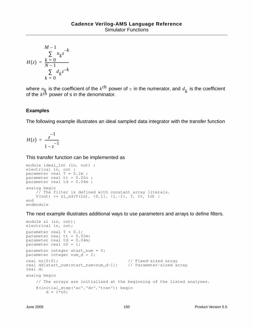
Cadence Verilog-AMS Language ReferenceSimulator Functions
where is the coefficient of the power of z in the numerator, and is the coefficientof the power of s in the denominator.
Examples
The following example illustrates an ideal sampled data integrator with the transfer function
This transfer function can be implemented as
module ideal_int (in, out) ;electrical in, out ;parameter real T = 0.1m ;parameter real tt = 0.02n ;parameter real td = 0.04m ;
analog begin// The filter is defined with constant array literals.V(out) <+ zi_nd(V(in), {0,1}, {1,-1}, T, tt, td) ;
endendmodule
The next example illustrates additional ways to use parameters and arrays to define filters.
module zi (in, out);electrical in, out;
parameter real T = 0.1;parameter real tt = 0.02m;parameter real td = 0.04m;parameter real n0 = 1;
parameter integer start_num = 0;parameter integer num_d = 2;
real nn[0:0]; // Fixed-sized arrayreal dd[start_num:start_num+num_d-1]; // Parameter-sized arrayreal d;
analog begin
// The arrays are initialized at the beginning of the listed analyses.
@(initial_step("ac","dc","tran")) begind = 1*n0;
H z( )
nkzk–
k 0=
M 1–∑
dkz k–
k 0=
N 1–∑
-----------------------------=
nk kth dkkth
H z( ) z1–
1 z1–
–-----------------=
June 2005 150 Product Version 5.5

Cadence Verilog-AMS Language ReferenceSimulator Functions
nn[start_num] = n0;dd[start_num] = d; dd[1] = -d;
end
V(out) <+ zi_nd( V(in), nn, dd, T, tt, td);endendmodule
Displaying Results
Verilog-A provides four tasks for displaying information: $strobe, $display, $monitor,and $write.
$strobe
Use the $strobe task to display information on the screen. $strobe and $display usethe same arguments and are completely interchangeable. $strobe is supported in bothanalog and digital contexts.
strobe_task ::=$strobe [ ( { list_of_arguments } ) ]
list_of_arguments ::=argument
| list_of_arguments , argument
The $strobe task prints a new-line character after the final argument. A $strobe taskwithout any arguments prints only a new-line character.
Each argument is a quoted string or an expression that returns a value.
Each quoted string is a set of ordinary characters, special characters, or conversionspecifications, all enclosed in one set of quotation marks. Each conversion specification inthe string must have a corresponding argument following the string. You must ensure that thetype of each argument is appropriate for the corresponding conversion specification.
You can specify an argument without a corresponding conversion specification. If you do, aninteger argument is displayed using the %d format, and a real argument is displayed using the%g format.
June 2005 151 Product Version 5.5
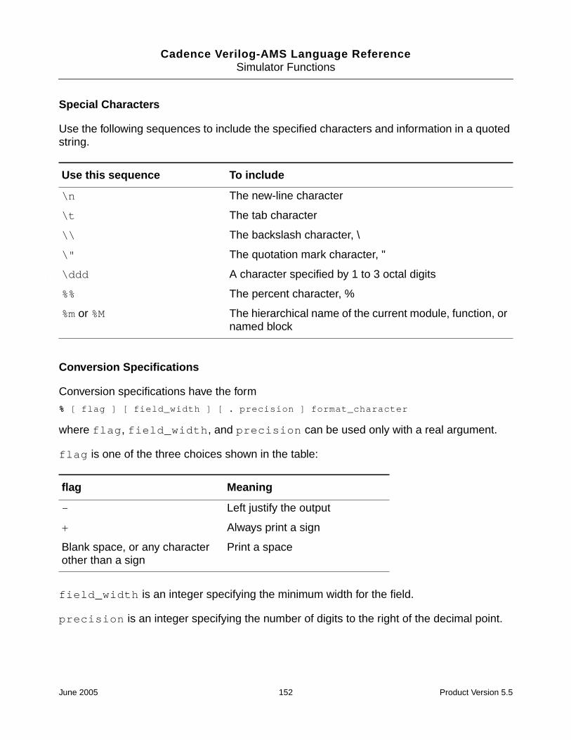
Cadence Verilog-AMS Language ReferenceSimulator Functions
Special Characters
Use the following sequences to include the specified characters and information in a quotedstring.
Conversion Specifications
Conversion specifications have the form
% [ flag ] [ field_width ] [ . precision ] format_character
where flag, field_width, and precision can be used only with a real argument.
flag is one of the three choices shown in the table:
field_width is an integer specifying the minimum width for the field.
precision is an integer specifying the number of digits to the right of the decimal point.
Use this sequence To include
\n The new-line character
\t The tab character
\\ The backslash character, \
\" The quotation mark character, "
\ddd A character specified by 1 to 3 octal digits
%% The percent character, %
%m or %M The hierarchical name of the current module, function, ornamed block
flag Meaning
- Left justify the output
+ Always print a sign
Blank space, or any characterother than a sign
Print a space
June 2005 152 Product Version 5.5

Cadence Verilog-AMS Language ReferenceSimulator Functions
format_character is one of the following characters.
Examples of $strobe Formatting
Assume that module format_module is instantiated in a netlist file with the instantiation
formatTest format_module
The module is defined as
module format_module ;integer ival ;real rval ;analog begin
ival = 98 ;rval = 123.456789 ;$strobe("Format c gives %c" , ival) ;$strobe("Format C gives %C" , ival) ;$strobe("Format d gives %d" , ival) ;$strobe("Format D gives %D" , ival) ;$strobe("Format e (real) gives %e" , rval) ;$strobe("Format E (real) gives %E" , rval) ;$strobe("Format f (real) gives %f" , rval) ;
format_character
Type ofArgument Output Example Output
b or B Binary format 00000000000000000000000000111000
c or C Integer ASCII character format
d or D Integer Decimal format 191, 48, -567
e or E Real Real, exponential format -1.0, 4e8,34.349e-12
f or F Real Real, fixed-point format 191.04, -4.789
g or G Real Real, exponential, or decimal format,whichever format results in theshortest printed output
9.6001, 7.34E-8,-23.1E6
h or H Integer Hexadecimal format 3e, 262, a38, fff, 3E,A38
o or O Integer Octal format 127, 777
r or R Real Engineering notation format 123,457M, 12.345K
s or S Stringconstant
String format
June 2005 153 Product Version 5.5

Cadence Verilog-AMS Language ReferenceSimulator Functions
$strobe("Format F (real) gives %F" , rval) ;$strobe("Format g (real)gives %g" , rval) ;$strobe("Format G (real)gives %G" , rval) ;$strobe("Format h gives %h" , ival) ;$strobe("Format H gives %H" , ival) ;$strobe("Format m gives %m") ;$strobe("Format M gives %M") ;$strobe("Format o gives %o" , ival) ;$strobe("Format O gives %O" , ival) ;$strobe("Format s gives %s" , "s string") ;$strobe("Format S gives %S" , "S string") ;$strobe("newline,\ntab,\tback-slash, \\") ;$strobe("doublequote,\"") ;
end
endmodule
When you run format_module, it displays
Format c gives bFormat C gives bFormat d gives 98Format D gives 98Format e gives 1.234568e+02Format E gives 1.234568e+02Format f gives 123.456789Format F gives 123.456789Format g gives 123.457Format G gives 123.457Format h gives 62Format H gives 62Format m gives formatTestFormat M gives formatTestFormat o gives 142Format O gives 142Format s gives s stringFormat S gives S stringnewline,tab, back-slash, \doublequote,"
$display
Use the $display task to display information on the screen. $display is supported in bothanalog and digital contexts.
display_task ::=$display [ ( { list_of_arguments } ) ]
list_of_arguments ::=argument
| list_of_arguments , argument
$display and $strobe use the same arguments and are completely interchangeable. Forguidance, see “$strobe” on page 151.
June 2005 154 Product Version 5.5
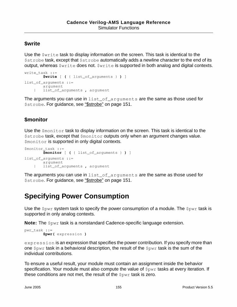
Cadence Verilog-AMS Language ReferenceSimulator Functions
$write
Use the $write task to display information on the screen. This task is identical to the$strobe task, except that $strobe automatically adds a newline character to the end of itsoutput, whereas $write does not. $write is supported in both analog and digital contexts.
write_task ::=$write [ ( { list_of_arguments } ) ]
list_of_arguments ::=argument
| list_of_arguments , argument
The arguments you can use in list_of_arguments are the same as those used for$strobe. For guidance, see “$strobe” on page 151.
$monitor
Use the $monitor task to display information on the screen. This task is identical to the$strobe task, except that $monitor outputs only when an argument changes value.$monitor is supported in only digital contexts.
$monitor_task ::=$monitor [ ( { list_of_arguments } ) ]
list_of_arguments ::=argument
| list_of_arguments , argument
The arguments you can use in list_of_arguments are the same as those used for$strobe. For guidance, see “$strobe” on page 151.
Specifying Power Consumption
Use the $pwr system task to specify the power consumption of a module. The $pwr task issupported in only analog contexts.
Note: The $pwr task is a nonstandard Cadence-specific language extension.
pwr_task ::=$pwr( expression )
expression is an expression that specifies the power contribution. If you specify more thanone $pwr task in a behavioral description, the result of the $pwr task is the sum of theindividual contributions.
To ensure a useful result, your module must contain an assignment inside the behaviorspecification. Your module must also compute the value of $pwr tasks at every iteration. Ifthese conditions are not met, the result of the $pwr task is zero.
June 2005 155 Product Version 5.5

Cadence Verilog-AMS Language ReferenceSimulator Functions
The $pwr task does not return a value and cannot be used inside other expressions. Instead,access the result by using the options and save statements in the analog simulationcontrol file. For example, using the following statement in the analog simulation control filesaves all the individual power contributions and the sum of the contributions in the modulenamed name:
name options pwr=all
For save, use a statement like the following:
save name:pwr
In each format, name is the name of a module.
For more information about the options statement, see Chapter 7 of the Spectre CircuitSimulator User Guide. For more about the save statement, see Chapter 8 of the SpectreCircuit Simulator User Guide.
Example// Resistor with power contribution‘include "disciplines.vams"
module Res(pos, neg);inout pos, neg;electrical pos, neg;parameter real r=5;
analog beginV(pos,neg) <+ r * I(pos,neg);$pwr(V(pos,neg)*I(pos,neg));
endendmodule
Working with Files
Verilog-A provides several functions for working with files. $fopen prepares a file for writing.$fstrobe and $fdisplay write to a file. $fclose closes an open file.
Opening a File
Use the $fopen function to open a specified file.
fopen_function ::=multi_channel_descriptor = $fopen ( "file_name" [ "io_mode"] ) ;
| fd = $fopen ( "file_name", type ) ;
type ::="r"
| "w"| "a"
June 2005 156 Product Version 5.5
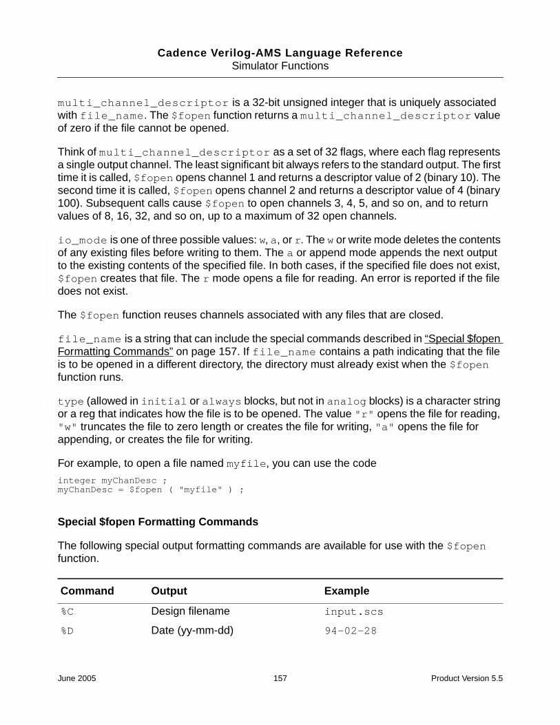
Cadence Verilog-AMS Language ReferenceSimulator Functions
multi_channel_descriptor is a 32-bit unsigned integer that is uniquely associatedwith file_name. The $fopen function returns a multi_channel_descriptor valueof zero if the file cannot be opened.
Think of multi_channel_descriptor as a set of 32 flags, where each flag representsa single output channel. The least significant bit always refers to the standard output. The firsttime it is called, $fopen opens channel 1 and returns a descriptor value of 2 (binary 10). Thesecond time it is called, $fopen opens channel 2 and returns a descriptor value of 4 (binary100). Subsequent calls cause $fopen to open channels 3, 4, 5, and so on, and to returnvalues of 8, 16, 32, and so on, up to a maximum of 32 open channels.
io_mode is one of three possible values: w, a, or r. The w or write mode deletes the contentsof any existing files before writing to them. The a or append mode appends the next outputto the existing contents of the specified file. In both cases, if the specified file does not exist,$fopen creates that file. The r mode opens a file for reading. An error is reported if the filedoes not exist.
The $fopen function reuses channels associated with any files that are closed.
file_name is a string that can include the special commands described in “Special $fopenFormatting Commands” on page 157. If file_name contains a path indicating that the fileis to be opened in a different directory, the directory must already exist when the $fopenfunction runs.
type (allowed in initial or always blocks, but not in analog blocks) is a character stringor a reg that indicates how the file is to be opened. The value "r" opens the file for reading,"w" truncates the file to zero length or creates the file for writing, "a" opens the file forappending, or creates the file for writing.
For example, to open a file named myfile, you can use the code
integer myChanDesc ;myChanDesc = $fopen ( "myfile" ) ;
Special $fopen Formatting Commands
The following special output formatting commands are available for use with the $fopenfunction.
Command Output Example
%C Design filename input.scs
%D Date (yy-mm-dd) 94-02-28
June 2005 157 Product Version 5.5

Cadence Verilog-AMS Language ReferenceSimulator Functions
The special output formatting commands can be followed by one or more modifiers, whichextract information from UNIX filenames. (To avoid opening a file that is already open, the %Ccommand must be followed by a modifier.) The modifiers are:
Any other character after a colon (:) signals the end of modifications. That character is copiedwith the previous colon.
The modifiers are typically used with the %C command although they can be used with any ofthe commands. However, when the output of a formatting command does not contain a / and“.”, the modifiers :t and :r return the whole name and the :e and :h modifiers return “.”. Asa result, be aware that using modifiers with formatting commands other than %C might notproduce the results you expect. For example, using the command
$fopen("%I:h.freq_dat") ;
opens a file named ..freq_dat.
You can use a concatenated sequence of modifiers. For example, if your design file name isres.ckt, and you use the statement
$fopen("%C:r.freq_dat") ;
then
%H Host name hal
%S Simulator type spectre
%P Unix process ID # 3641
%T Time (24hh:mm:ss) 15:19:25
%I Instance name opamp3
%A Analysis name dc0p, timeDomain, acSup
Modifier Extracted information
:r Root (base name) of the path for the file
:e Extension of the path for the file
:h Head of the path for any portion of the file before the last /
:t Tail of the path for any portion of the file after the last /
:: The (:) character itself
Command Output Example
June 2005 158 Product Version 5.5

Cadence Verilog-AMS Language ReferenceSimulator Functions
■ %C is the design filename (res.ckt)
■ :r is the root of the design filename (res)
■ .freq_dat is the new filename extension
As a result, the name of the opened file is res.freq_dat.
The following table shows the various filenames generated from a design filename (%C) of
/users/maxwell/circuits/opamp.ckt
by using different formatting commands and modifiers.
Reading from a File
Use the $fscanf function to read information from a file.
fscanf_function ::=$fscanf (multi_channel_descriptor , "format" { , storage_arg } )
The multi_channel_descriptor that you specify must have a value that is associatedwith one or more currently open files. The format describes the matching operation donebetween the $fscanf storage arguments and the input from the data file. The $fscanf
Command and Modifiers Resulting Opened File
$fopen("%C"); None, because the design file cannot be overwritten.
$fopen("%C:r"); /users/maxwell/circuits/opamp
$fopen("%C:e"); ckt
$fopen("%C:h"); /users/maxwell/circuits
$fopen("%C:t"); opamp.ckt
$fopen("%C::"); /users/maxwell/circuits/opamp.ckt:
$fopen("%C:h:h"); /users/maxwell
$fopen("%C:t:r"); opamp
$fopen("%C:r:t"); opamp
$fopen("/tmp/%C:t:r.raw"); /tmp/opamp.raw
$fopen("%C:e%C:r:t"); ckt.opamp
$fopen("%C:r.%I.dat" ); /users/maxwell/circuits/opamp.opamp3.dat
June 2005 159 Product Version 5.5

Cadence Verilog-AMS Language ReferenceSimulator Functions
function sequentially attempts to match each formatting command in this string to the inputcoming from the file. After the formatting command is matched to the characters from theinput stream, the next formatting command is applied to the next input coming from the file.If a formatting command is not a skipping command, the data read from the file to match aformatting command is stored in the formatting command’s corresponding storage_arg.The first storage_arg corresponds to the first nonskipping formatting command; thesecond storage_arg corresponds to the second nonskipping formatting command. Thismatching process is repeated between all formatting commands and input data. Theformatting commands that you can use are the same as those used for $strobe. See“$strobe” on page 151 for guidance.
For example, the following statement reads data from the file designated by fptr1 andplaces the information in variables called db1 and int.
$fscanf(fptr1, "Double = %e and Integer = %d", dbl, int);
Writing to a File
Verilog-A provides three input/output functions for writing to a file: $fstrobe, $fdisplay,and $fwrite. The $fstrobe and $fdisplay functions use the same arguments and arecompletely interchangeable. The $fwrite function is similar but does not insert automaticcarriage returns in the output.
$fstrobe
Use the $fstrobe function to write information to a file.
fstrobe_function ::=$fstrobe (multi_channel_descriptor {,list_of_arguments })
list_of_arguments ::=argument
| list_of_arguments , argument
The multi_channel_descriptor that you specify must have a value that is associatedwith one or more currently open files. The arguments that you can use inlist_of_arguments are the same as those used for $strobe. See “$strobe” onpage 151 for guidance.
For example, the following code fragment illustrates how you might write simultaneously totwo open files.
integer mcd1 ;integer mcd2 ;integer mcd ;@(initial_step) begin
mcd1 = $fopen("file1.dat") ;mcd2 = $fopen("file2.dat") ;
June 2005 160 Product Version 5.5
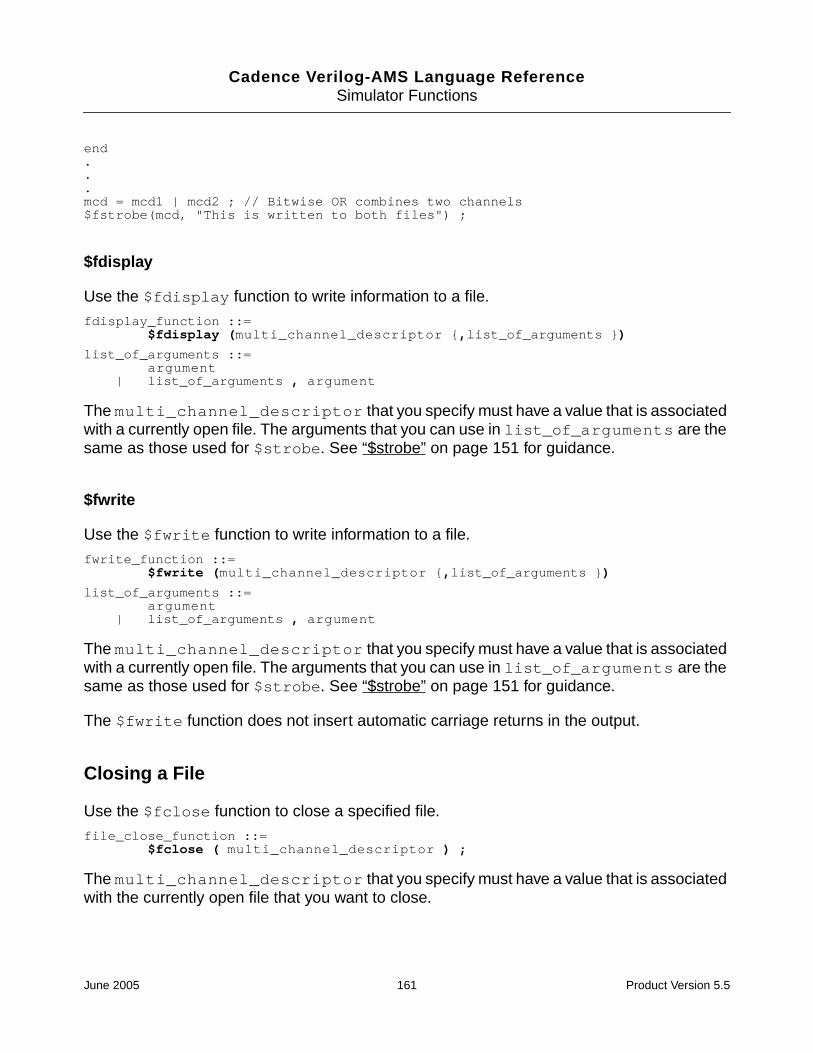
Cadence Verilog-AMS Language ReferenceSimulator Functions
end...mcd = mcd1 | mcd2 ; // Bitwise OR combines two channels$fstrobe(mcd, "This is written to both files") ;
$fdisplay
Use the $fdisplay function to write information to a file.
fdisplay_function ::=$fdisplay (multi_channel_descriptor {,list_of_arguments })
list_of_arguments ::=argument
| list_of_arguments , argument
The multi_channel_descriptor that you specify must have a value that is associatedwith a currently open file. The arguments that you can use in list_of_arguments are thesame as those used for $strobe. See “$strobe” on page 151 for guidance.
$fwrite
Use the $fwrite function to write information to a file.
fwrite_function ::=$fwrite (multi_channel_descriptor {,list_of_arguments })
list_of_arguments ::=argument
| list_of_arguments , argument
The multi_channel_descriptor that you specify must have a value that is associatedwith a currently open file. The arguments that you can use in list_of_arguments are thesame as those used for $strobe. See “$strobe” on page 151 for guidance.
The $fwrite function does not insert automatic carriage returns in the output.
Closing a File
Use the $fclose function to close a specified file.
file_close_function ::=$fclose ( multi_channel_descriptor ) ;
The multi_channel_descriptor that you specify must have a value that is associatedwith the currently open file that you want to close.
June 2005 161 Product Version 5.5

Cadence Verilog-AMS Language ReferenceSimulator Functions
Exiting to the Operating System
Use the $finish function to make the simulator exit and return control to the operatingsystem.
finish_function ::=$finish [( msg_level )] ;
msg_level ::=0 | 1 | 2
The msg_level value determines which diagnostic messages print before control returns tothe operating system. The default msg_level value is 1.
Note: In this release, the $finish function always behaves as though the msg_level valueis 0, regardless of the value you actually use.
For example, to make the simulator exit, you might code
$finish ;
Entering Interactive Tcl Mode
Use the $stop function to make the simulator enter interactive mode and display a Tclprompt.
stop_function ::=$stop [( msg_level )] ;
msg_level ::=0 | 1 | 2
The msg_level value determines which diagnostic messages print before the simulatorstarts the interactive mode. The default msg_level value is 1.
msg_level Messages printed
0 None
1 Simulation time and location
2 Simulation time, location, and statistics about the memoryand CPU time used in the simulation
msg_level Messages printed
0 None
June 2005 162 Product Version 5.5

Cadence Verilog-AMS Language ReferenceSimulator Functions
For example, to make the simulator go interactive, you might code
$stop ;
User-Defined Functions
Verilog-A supports user-defined functions. By defining and using your own functions, you cansimplify your code and enhance readability and reuse. Each function can be a digital function(as defined in IEEE 1364-1995 Verilog HDL) or an analog function.
Declaring an Analog User-Defined Function
To define an analog function, use this syntax:
analog_function_declaration ::=analog function [ type ] function_identifier ;function_item_declaration {function_item_declaration}statementendfunction
type ::=integer
| real
function_item_declaration ::=input_declaration
| block_item_declaration
block_item_declaration ::=integer_declaration
| real_declaration
type is the type of the value returned by the function. The default value is real.
statement cannot include analog operators and cannot define module behavior.Specifically, statement cannot include
■ ddt operator
■ idt operator
■ idtmod operator
1 Simulation time and location
2 Simulation time, location, and statistics about the memoryand CPU time used in the simulation
msg_level Messages printed
June 2005 163 Product Version 5.5

Cadence Verilog-AMS Language ReferenceSimulator Functions
■ Access functions
■ Contribution statements
■ Event control statements
■ Simulator library functions, except that you can include the functions in the next list
statement can include references to
■ $vt
■ $vt(temp)
■ $temperature
■ $realtime
■ $abstime
■ analysis
■ $strobe
■ $display
■ $write
■ $fopen
■ $fstrobe
■ $fdisplay
■ $fwrite
■ $fclose
■ All mathematical functions
You can declare local variables to be used in the function.
Each function you define must have at least one declared input. Each function must alsoassign a value to the implicitly defined internal variable with the same name as the function.
For example,
analog function real chopper ;input sw, in ; // The function has two declared inputs.real sw, in ;
//The next line assigns a value to the implicit variable, chopper.chopper = ((sw > 0) ? in : -in) ;
endfunction
June 2005 164 Product Version 5.5

Cadence Verilog-AMS Language ReferenceSimulator Functions
The chopper function takes two variables, sw and in, and returns a real result. You can usethe function in any subsequent function definition or in the module definition.
Calling a User-Defined Analog Function
To call a user-defined analog function, use the following syntax.
analog_function_call ::=function_identifier ( expression { , expression } )
function_identifier must be the name of a defined function. Each expression isevaluated by the simulator before the function runs. However, do not rely on havingexpressions evaluated in a certain order because the simulator is allowed to evaluate themin any order.
An analog function must not call itself, either directly or indirectly, because recursive functionsare illegal. Analog function calls are allowed only inside of analog blocks.
The module phase_detector illustrates how the chopper function can be called.
module phase_detector(lo, rf, if0) ;inout lo, rf, if0 ;electrical lo, rf, if0 ;parameter real gain = 1 ;
function real chopper;input sw, in;real sw, in;chopper = ((sw > 0) ? in : -in);
endfunction
analogV(if0) <+ gain * chopper(V(lo),V(rf)); //Call from within the analog block.
endmodule
June 2005 165 Product Version 5.5

Cadence Verilog-AMS Language ReferenceSimulator Functions
June 2005 166 Product Version 5.5

Cadence Verilog-AMS Language Reference
10Instantiating Modules and Primitives
Chapter 2, “Creating Modules,” discusses the basic structure of Cadence® Verilog®-Alanguage modules. This chapter discusses how to instantiate Verilog-A modules within othermodules. Module declarations cannot nest in one another; instead, you embed instances ofmodules in other modules. By embedding instances, you build a hierarchy extending from theinstances of primitive modules up through the top-level modules.
The following sections discuss
■ Instantiating Verilog-A Modules on page 168
■ Connecting the Ports of Module Instances on page 171
■ Overriding Parameter Values in Instances on page 173
■ Instantiating Analog Primitives on page 176
■ Using an m-factor (Multiplicity Factor) on page 177
■ Including Verilog-A Modules in Spectre Subcircuits on page 179
June 2005 167 Product Version 5.5

Cadence Verilog-AMS Language ReferenceInstantiating Modules and Primitives
Instantiating Verilog-A Modules
Use the following syntax to instantiate modules in other modules.
module_instantiation ::=module_identifier [ parameter_value_assignment ] instance_list
instance_list ::=module_instance { , module_instance} ;
module_instance ::=name_of_instance ( [ list_of_module_connections ] )
name_of_instance ::=module_instance_identifier [ constant_range ]
list_of_module_connections ::=ordered_port_connection { , ordered_port_connection }
| named_port_connection { , named_port_connection }
ordered_port_connection ::=[ net_expression ]
named_port_connection ::=. port_identifier ( [ net_expression ] )
net_expression ::=net_identifier
| net_identifier [ constant_expression ]| net_identifier [ constant_range ]
constant_range ::=constant_expression : constant_expression
The instance_list expression is discussed in the following sections. Theparameter_value_assignment expression is discussed in “Overriding ParameterValues in Instances” on page 173.
Creating and Naming Instances
This section illustrates how to instantiate modules. Consider the following module, whichdescribes a gain block that doubles the input voltage.
module vdoubler (in, out) ;input in ;output out ;electrical in, out ;analog
V(out) <+ 2.0 * V(in) ;endmodule
Two of these gain blocks are connected, with the output of the first becoming the input of thesecond. The schematic looks like this.
qin aa1 qoutvd1 vd2
June 2005 168 Product Version 5.5

Cadence Verilog-AMS Language ReferenceInstantiating Modules and Primitives
This higher-level component is described by module vquad, which creates two instances,named vd1 and vd2, of module vdoubler. Module vquad also defines external portscorresponding to those shown in the schematic.
module vquad (qin, qout) ;input qin ;output qout ;electrical qin, qout ;wire aa1 ;vdoubler vd1 (qin, aa1) ;vdoubler vd2 (aa1, qout) ;endmodule
Creating Arrays of Instances
The range specification on the module_instance_identifier allows you to createarrays of instances.
name_of_instance ::=module_instance_identifier [ constant_range ]
However, a module_instance_identifier used to create an array of instances (anAOI_identifier) is restricted to being purely digital and cannot instantiate an analogobject at any level. That means that you cannot use:
■ An analog primitive or a connection module as the AOI_identifier.
■ Inherited connection attributes, mfactor attributes, or dynamic parameters in theAOI_identifier.
In addition, you cannot use a VHDL design unit as the AOI_identifier.
You cannot connect to the AOI_identifier a net or bus that is declared to be analog.Nets or buses of undetermined discipline are forced to the default discipline when theyconnect to an AOI_identifier.
When you use both the ncelab -dresolution and -messages options, the elaboratornotifies you when it encounters an array of instances. Regardless of the number of arrays ofinstances in the design, the elaborator produces only a single message. For example, youdefine the following modules.
/* Digital module instance array */module pmem();
wire [15:0] xxpab,pab;nmos #0.06 npab[15:0] (xxpab,pab,1’b1);
endmodule
/* Instantiate both digital and analog modules */module tmp ();
pmem pmem();ana ana();
endmodule
June 2005 169 Product Version 5.5

Cadence Verilog-AMS Language ReferenceInstantiating Modules and Primitives
/* Analog module */module ana();
electrical v;real vValue;initial begin
vValue = 0.1;#100;vValue = 1.5;
endanalog begin
V(v) <+ vValue;end
endmodule
When you run ncelab with both the -dresolution and -messages options, the followingmessage is produced.
nmos #0.06 npab[15:0] (xxpab,pab,1’b1);|
ncelab: *W,AMSAOIW (./test.v,10|14): An array of instances was encountered in theAMS design. Only pure digital array of instance hierarchies are allowed in AMSdesigns.
Mapping Instance Ports to Module Ports
When you instantiate a module, you must specify how the actual ports listed in the instancecorrespond to the formal ports listed in the defining module. Module vquad, in the previousexample, demonstrates one of the two methods provided in Verilog-A. Module vquad usesan ordered list, where instance vd1’s first actual port name qin maps to vdoubler’s firstformal port name in. Instance vd1’s second actual port name aa1 maps to vdoubler’ssecond formal port name, and so on.
You can also map actual ports to the formal ports in the defining module explicitly, using namepairs. If you choose this approach, the order of the ports does not matter.
You cannot mix the two kinds of mapping within a single instance.
Mapping Ports with Ordered Lists
To use ordered lists to map actual ports listed in the instance to the formal ports listed in thedefining module, ensure that the instance ports are in the same order as the defining moduleports. For example, consider the following module child and the module instantiatorthat instantiates it.
module child (ina, inb, out) ;input [0:3] ina ;input inb ;output out ;electrical [0:3] ina ;electrical inb ;
June 2005 170 Product Version 5.5

Cadence Verilog-AMS Language ReferenceInstantiating Modules and Primitives
electrical out ;endmodule
module instantiator (conin, conout) ;input [0:6] conin ;output conout ;electical [0:6] conin ;electrical conout ;child child1 (conin [1:4], conin [6], conout) ;end module
You can tell from the order of port names in these modules that port ina[0] in module childmaps to port conin[1] in instance child1. Similarly, port inb in child maps to portconin[6] in instance child1. Port out in child maps to port conout in instancechild1.
Mapping Ports with Name Pairs
You can also link the formal ports in a defining module and the actual ports in an instanceexplicitly by pairing the port names. A period and the formal port name come first in each pair,followed, in parentheses, by the actual port name used in the instance. For example, in thismodule instantiation statement,
adc2 low (.in(rem_chain), .out(bout[1]), .outb()) ;
the formal names in, out, and outb, are from the defining module, and the actual namesrem_chain and bout[1] are used in the instantiating module. The empty set ofparentheses adjacent to outb show that the outb port is not used in this instance.
Ensure that the first name in each pair is a name specified on the module statement of thedefining module. Then ensure that the second name, the actual one used in the instance andin the instantiating module, is one of the following:
■ A simple net identifier
■ A scalar member of a vector net or port declared within the instantiating module
■ A sub-range of a vector net declared within the instantiating module
Connecting the Ports of Module Instances
Developing modules that describe components is an important step on the way to the overallgoal of simulating a system. But an equally important step is combining those componentstogether so that they represent the system as a whole. This section discusses how to connectmodule instances, using their ports, to describe the structure and behavior of the system youare modeling.
June 2005 171 Product Version 5.5

Cadence Verilog-AMS Language ReferenceInstantiating Modules and Primitives
Consider again the modules vdoubler and vquad, which describe this schematic.
module vdoubler (in, out) ;input in ;output out ;electrical in, out ;analog
V(out) <+ 2.0 * V(in) ;endmodule
module vquad (qin, qout) ;input qin ;output qout ;electrical qin, qout ;wire aa1 ;vdoubler vd1 (qin, aa1) ;vdoubler vd2 (aa1, qout) ;endmodule
This time, note how the module instantiation statements in vquad use port names toestablish a connection between output port aa1 of instance vd1 and input port aa1 ofinstance vd2.
You can establish the same connections by using name pairs, as illustrated in the followingtwo instantiation statements
vdoubler vd1 (.out (aa1), .in (qin)) ;vdoubler vd2 (.in (aa1), .out (qout)) ;
Module instantiation statements like
vdoubler vd1 (qin, qout) ;vdoubler vd2 (qin, qout) ;
establish different connections. These statements describe a system where the gain blocksare connected in parallel, with this schematic.
qin aa1 qoutvd1 vd2
qin qout
vd1
vd2
June 2005 172 Product Version 5.5

Cadence Verilog-AMS Language ReferenceInstantiating Modules and Primitives
Port Connection Rules
You can connect the ports described in the vdoubler instances because the ports are allanalog, are defined with compatible disciplines, and are the same size. To generalize,
■ All analog ports connected to a net are compatible with each other. You can connect bothanalog and digital ports to the same net if you provide appropriate connect statements.
■ You must ensure that the sizes of connected ports and nets match. In other words, youcan connect a scalar port to a scalar net, and a vector port to a vector net orconcatenated net expression of the same width.
Overriding Parameter Values in Instances
As noted earlier, the syntax for the module instantiation statement is
module_identifier [ parameter_value_assignment ] instance_list
The following sections discuss the parameter_value_assignment expression, whichis further defined as
parameter_value_assignment ::=#( ordered_param_override_list )
| #( named_param_override_list )
ordered_param_override_list ::=expression { , expression }
named_param_override_list ::=named_param_override { , named_param_override }
named_param_override ::=. parameter_identifier ( expression )
By default, instances of modules inherit any parameters specified in their defining module. Ifyou want to change any of the default parameter values, you can do so on the moduleinstantiation statement itself, or from other modules and instances by using the defparamstatement. The defparam statement is particularly useful if you want to change parametersthroughout your modules from a single location.
Overriding Parameter Values from the Instantiation Statement
Using the module instantiation statement, you can assign values to parameters in two ways.You can assign values in the order the parameters are declared, or you can assign values byexplicitly referring to parameter names. The new values must be constant expressions.
June 2005 173 Product Version 5.5

Cadence Verilog-AMS Language ReferenceInstantiating Modules and Primitives
Overriding Parameter Values with Ordered Lists
To override parameters using an ordered list of replacement values you must ensure that thelist specifies replacement values in the same order that the parameters are defined in thedefining module. You are not required to specify replacement values for every definedparameter, but if you omit any value you must omit every value from then on. In other words,you cannot skip over selected parameters. If a parameter does not need a new value,however, you can specify a replacement value equal to the default value.
Consider the two instances, weakp and plainp, instantiated within module m.
module m ;voltage clk ;electrical out_a, in_a ;mosp # (2e-6, 1e-6) weakp (out_a, in_a, clk);//Overriding param values by ordermosp plainp (out_b, in_b, clk) ;endmodule ;
The weakp module instantiation statement overrides the first two parameters given in thedefining module, mosp, giving the first parameter the new value 2e-6 and the secondparameter the value 1e-6. The plainp module instantiation statement has no parameteroverride expression, so the parameters assume their default values.
Overriding Parameter Values By Name
You can also override parameter values in an instantiated module by pairing the parameternames to be changed with the values they are to receive. A period and the parameter namecome first in each pair, followed by the new value in parentheses. The parameter name mustbe the name of a parameter in the defining module of the module being instantiated. Whenyou override parameter values by name, you are not required to specify values for everyparameter.
Consider this modified definition of module vdoubler. This version has three parameters,parm1, parm2, and parm3.
module vdoubler (in, out) ;input in ;output out ;electrical in, out ;parameter parm1 = 0.2,
parm2 = 0.1,parm3 = 5.0 ;
analogV(out) <+ (parm1 + parm2 + parm3) * V(in) ;
endmodule
module vquad (qin, qout) ;input qin ;output qout ;vdoubler # (.parm3(4.0)) vd1 (qin, aa1) ; // Overriding by namevdoubler # (.parm1(0.3), .parm2(0.2)) vd2 (aa1, qout) ; // Overriding by name
June 2005 174 Product Version 5.5

Cadence Verilog-AMS Language ReferenceInstantiating Modules and Primitives
vdoubler # (0.3, 0.2) vd3 (aa1, qout) ; // By orderendmodule
The module instantiation statement for instance vd1 overrides parameter parm3 by name tospecify that the value for parm3 should be changed to 4.0. The other two parameters retainthe default values 0.2 and 0.1. The module instantiation statement for vd3 uses an orderedlist to override the first two parameters, parm1, and parm2. Parameter parm3 retains thedefault value 5.0.
Overriding Parameter Values Using defparam
Use the defparam statement to set parameter values in any module instance throughout themodule hierarchy. With this capability, for example, you can group all your parameter overrideassignments together in a single module. The syntax is
defparam param = constant_exp { , param = constant_exp } ;
param must be a complete hierarchical path for the parameter whose value you want tochange in a module instance. constant_exp must be an expression involving onlyconstant numbers and parameters that are defined in the same module containing thedefparam statement.
For example, as the following code demonstrates, you could remove the parameter overridesfrom module vquad and put them in a new module, annotate.
module vdoubler (in, out) ;input in ;output out ;electrical in, out ;parameter parm1 = 0.2,
parm2 = 0.1,parm3 = 5.0 ;
analogV (out) <+ (parm1 + parm2 + parm3) * V (in) ;
endmodule
module vquad (qin, qout) ;input qin ;output qout ;vdoubler vd1 (qin, aa1) ;vdoubler vd2 (aa1, qout) ;endmodule
module annotate ;defparam
vquad.vd1.parm3 = 4.0,vquad.vd2.parm1 = 0.3,vquad.vd2.parm2 = 0.2;
endmodule
June 2005 175 Product Version 5.5

Cadence Verilog-AMS Language ReferenceInstantiating Modules and Primitives
Precedence Rules for Overriding Parameter Values
Use the following rules to determine which parameter override takes precedence when aparameter value is overridden by more than one assignment.
■ If overrides take place at different levels of the module hierarchy, the highest leveloverride takes precedence.
■ If overrides take place at the same level of the module hierarchy, an override done by thedefparam statement takes precedence over overrides done by module instantiationstatements.
Instantiating Analog Primitives
The remaining sections of the chapter describe how to instantiate some analog primitives inyour code. For more information, see the “Preparing the Design: Using Analog Primitives andSubcircuits” chapter of the Cadence AMS Simulator User Guide.
As you can instantiate Verilog-A modules in other Verilog-A modules, you can instantiateSpectre and SPICE masters in Verilog-A modules. You can also instantiate models andsubcircuits in Verilog-A modules. For example, the following Verilog-A module instantiatestwo Spectre primitives: a resistor and an isource.
module ri_test (pwr, gnd) ;electrical pwr, gnd ;parameter real ibias = 10u, ampl = 1.0 ;electrical in, out ;
resistor #(.r(100K)) RL (out, pwr) ; //Instantiate resistorisource #(.dc(ibias)) Iin (gnd, in) ; //Instantiate isource
endmodule
When you connect a net of a discrete discipline to an analog primitive, the simulatorautomatically inserts a connect module between the two.
However, some instances require parameter values that are not directly supported by theVerilog-A language. The following sections illustrate how to set such values in theinstantiation statement.
Instantiating Analog Primitives that Use Array Valued Parameters
Some analog primitives take array valued parameters. For example, you might instantiate thesvcvs primitive like this:
module fm_demodulator(vin, vout, vgnd) ;input vin, vgnd ;output vout ;
June 2005 176 Product Version 5.5

Cadence Verilog-AMS Language ReferenceInstantiating Modules and Primitives
electrical vin, vout, vgnd ;parameter real gain = 1 ;
svcvs #(.gain(gain),.poles({-1M, 0, -1M, 0}))af_filter (vout, vgnd, vin, vgnd) ;
analog begin...
end
endmodule
This fm_demodulator module sets the array parameter poles to a comma-separated listenclosed by a set of square brackets.
Instantiating Modules that Use Unsupported Parameter Types
Spectre built-in primitives take parameter values that are not supported directly by theVerilog-A language. The following cases illustrate how to instantiate such modules.
To set a parameter that takes a string type value, set the value to a string constant. Forexample, the next fragment shows how you might set the file parameter of the vsourcedevice.
vsource #(.type("pwl"), .file("mydata.dat") V1(src,gnd);
To set an enumerated parameter in an instance of a Spectre built-in primitive, enclose theenumerated value in quotation marks. For example, the next fragment sets the parametertype to the value pulse.
vsource #(.type("pulse"),.val1(5),.period(50u)) Vclk(clk,gnd);
Using an m-factor (Multiplicity Factor)
An m-factor is a value that can be inherited down a hierarchy of instances. Circuit designersuse m-factors to mimic parallel copies of identical devices without having to instantiate largesets of devices in parallel. The value of the inherited m-factor in a particular module instanceis the product of the m-factor values in the ancestors of the instance and of the m-factor valuein the instance itself. If there are no passed m-factors in the instance or in the ancestors ofthe instance, the value of the m-factor is one.
To enable m-factors in Verilog-AMS, the AMS simulator supports two Cadence attributes:passed_mfactor and inherited_mfactor. The former is used to pass the m-factordown the hierarchy and the latter is used to access the value of the m-factor. Typically, theAMS netlister inserts the passed_mfactor attribute so that you only need to insert theinherited_mfactor parameter.
June 2005 177 Product Version 5.5

Cadence Verilog-AMS Language ReferenceInstantiating Modules and Primitives
Passing an m-factor Down the Hierarchy
To pass an m-factor down the hierarchy, you
1. Use the passed_mfactor attribute to specify which parameter is the m-factor.
2. Pass the specified m-factor parameter, with the desired m-factor value, to the instance.
For example, the following statement illustrates how to pass an m-factor parameter called mdown the hierarchy.
one #(.m(3)) (* integer passed_mfactor = "m"; *) One();
This example specifies an m-factor parameter called m, gives it the value 3, and passes thatvalue down to instance One of the module called one. The module being instantiated doesnot have to have the m parameter declared in its interface.
Accessing an Inherited m-factor
To use an inherited m-factor, you use the inherited_mfactor attribute on a parameterdeclaration. Using this attribute on a parameter declaration sets the value of the parameterto the value of the m-factor inherited by the module.
For example, the following statement illustrates how to access an m-factor parameter calledm.
parameter real (* integer inherited_mfactor; *) m=1;
There is an alternative attribute form that leads to a statement like this.
(* inherited_mfactor *) parameter real m=1;
Example: Using an m-factor
The following example illustrates how the m-factor value is passed down the hierarchy andhow the effective value is the product of the m-factors in the current instance and in theancestors of the current instance.
//Verilog-AMS HDL for "amslib", "top" "verilogams"
‘include "constants.vams"‘include "disciplines.vams"
module top;resistor R1(a,b);one #(.m(3)) (* integer passed_mfactor = "m"; *) One();
// The above sets the m-factor for instance One to 3.endmodule
//Verilog-AMS HDL for "amslib", "one" "verilogams"
June 2005 178 Product Version 5.5

Cadence Verilog-AMS Language ReferenceInstantiating Modules and Primitives
‘include "constants.vams"‘include "disciplines.vams"
module one ( );parameter real (* integer inherited_mfactor; *) m=1;resistor R1(a,b);two Two();analog $strobe ("Inherited mfactor in module one is %f",m);
// Value of m-factor is 3, as set in module top.endmodule
//Verilog-AMS HDL for "amslib", "two" "verilogams"
‘include "constants.vams"‘include "disciplines.vams"
module two ( );three #(.m(2)) (* integer passed_mfactor="m";*) Three();
// m-factor is not accessed in this module, but a factor of 2// is added.endmodule
//Verilog-AMS HDL for "amslib", "three" "verilogams"
‘include "constants.vams"‘include "disciplines.vams"module three ( );
parameter real (* integer inherited_mfactor; *) m=1;// The effective value of m-factor is now 3 * 2 = 6.
resistor R1(a,b);four Four(); // No m-factor is specified.analog $strobe ("Inherited mfactor in module three is %f",m);
endmodule
//Verilog-AMS HDL for "amslib", "four" "verilogams"
‘include "constants.vams"‘include "disciplines.vams"module four ( );
resistor R1(a,b);endmodule
When you simulate, these modules produce output like the following.
ncsim> runinherited mfactor in module one is 3.000000inherited mfactor in module three is 6.000000
Including Verilog-A Modules in Spectre Subcircuits
Users of AMS Designer can instantiate Spectre cells in their Verilog-AMS code. By using theahdl_include statement, those Spectre cells can, in turn, instantiate behavioral Verilog-A
June 2005 179 Product Version 5.5

Cadence Verilog-AMS Language ReferenceInstantiating Modules and Primitives
modules (but not SpectreHDL modules). This situation, which users of Spectre libraries oftenencounter, is summarized by the following diagram.
To set up a hierarchy like this one, you use an ahdl_include statement in the Spectresubcircuit to include the Verilog-A module. The included Verilog-A module must be a leaf-levelcell. In other words, the Verilog-A module can contain only behavioral code; structural codeis not allowed.
The ahdl_include statement used in the Spectre subcircuit has the following format.
ahdl_include "filename"
For filename, use either a full or a relative path that resolves across your network. For aVerilog-A file, filename must have a .va file extension.
For example, to include in your Spectre subcircuit a Verilog-A npn instance with the nameahdlNpn, you use a statement like the following,
ahdl_include "/usr/ahdlNpn.va"
Be sure that you make the Spectre subcircuit available by defining the MODELPATH variable.For more information about this procedure, see the “Using Subcircuits and Models Written inSPICE or Spectre” section, in Chapter 3, of the Cadence AMS Simulator User Guide.
Verilog-AMS module
Spectre instance
...
...
Spectre subcircuit
Verilog-A instance
...
...
Verilog-A module
Behavioral code
June 2005 180 Product Version 5.5

Cadence Verilog-AMS Language Reference
11Mixed-Signal Aspects of Verilog-AMS
The Cadence® Verilog®-AMS language brings analog and digital modeling together in asingle language. This chapter describes the mixed-signal features of Verilog-AMS and howthe continuous (analog) and discrete (digital) domains interact.
Fundamental Mixed-Signal Concepts
Becoming familiar with the following terms will help you understand the discussion in thischapter.
Domains
The domain of a value refers to the method used to calculate the value. In Verilog-AMS,
■ The potentials and flows described in natures are calculated in the continuous domain.
■ Register contents and the states of gate primitives are calculated in the discrete domain.
■ The values of real and integer variables are calculated in either the continuous ordiscrete domain, depending on the context in which their values are assigned. Thedomain of a variable is that of the context from which its value is assigned.
Values calculated in the discrete domain change value instantaneously and only at integermultiples of a minimum resolvable time. Values calculated in the continuous domain varycontinuously.
Contexts
Statements in a Verilog-AMS module description can appear in the body of an analog block,in the body of an initial or always block, or outside of any block. Statements that appearin an analog block are in the continuous context; statements in any other location are inthe discrete context. A particular variable can be assigned values in either context, but notin both contexts.
June 2005 181 Product Version 5.5

Cadence Verilog-AMS Language ReferenceMixed-Signal Aspects of Verilog-AMS
Nets, Nodes, Ports, and Signals
In Verilog-AMS, hierarchical structures are created when higher-level modules createinstances of lower level modules and communicate with those instances through input,output, and bidirectional ports. A port represents the physical connection of an expression inthe instantiating or parent module with an expression in the instantiated or child module. Theexpressions, which can include registers, variables, and nets of both continuous and discretedisciplines, are referred to as connections. A port of an instantiated module has two nets,the upper connection, which is a net in the instantiating module, and the lower connection,which is a net in the instantiated module.
A net is said to be in the discrete domain if it has an associated discrete discipline. A net is inthe continuous domain if it has an associated continuous discipline. A signal is a hierarchicalcollection of nets that, because of port connections, are contiguous. If all the nets that makeup a signal are in the discrete domain, the signal is a digital signal. If all the nets that makeup a signal are in the continuous domain, the signal is an analog signal. A signal thatconsists of nets from both domains is called a mixed signal. Similarly, a port whoseconnections are both analog is an analog port, a port whose connections are both digital isa digital port, and a port with one analog connection and one digital connection is a mixedport.
Nets and variables in the continuous domain are termed continuous nets and continuousvariables. Nets and variables in the discrete domain are termed discrete nets and discretevariables.
If a signal is analog or mixed, then it is associated with a node. Regardless of the number ofanalog nets in an analog or mixed signal, and regardless of how the analog nets in a mixedsignal are interspersed with digital nets, the analog portion of an analog or mixed signal isrepresented by only a single electrical node. This guarantees that at any instant in time theanalog portion of a mixed or analog signal has one, and only one, value that represents itspotential with respect to ground.
Analog nodes and branches are allowed only as arguments to signal access functions,analog functions, and analog primitive and module instantiations. They cannot be connectedto digital primitives.
For additional information, see Appendix A, “Nodal Analysis.”
Mixed-signal and Net Disciplines
The discipline of a continuous net specifies the tolerance (abstol) used to calculate thepotential of the associated node. A mixed signal might have multiple continuous nets ofdifferent compatible continuous disciplines, with different abstol values. In this case, the
June 2005 182 Product Version 5.5

Cadence Verilog-AMS Language ReferenceMixed-Signal Aspects of Verilog-AMS
abstol of the associated node is the smallest of the abstol values specified in thedisciplines associated with the continuous nets of the signal.
Behavioral Interaction
Verilog-AMS supports various types of blocks used to describe behavior. In general, digitalbehavior is described in initial and always blocks and analog behavior is described inanalog blocks. In a Verilog-AMS module, you can have, at most, one analog block and anynumber of initial and always blocks.
The nets and variables of each domain can be referenced in the other context, which is howinformation passes between the continuous and discrete domains. Read operations of netsand variables in both domains are allowed from both contexts. Write operations of nets andvariables are only allowed from within the context of their domain.
The following example illustrates some of these capabilities.
integer above; // Will be an analog-owned variable.integer d; // Will be a digital-owned variable.
electrical in;
always begin // Enter the digital context.if ( above ) // Read the analog variable in the digital context.#5 d = 1; // Write the variable d in the digital context.
if ( below )#5 d = 0; // d, because written in digital context, is owned by digital.
end
analog begin // Enter the analog context.@ (cross (V(in) - 2.5, +1 ) )
above = 1; // Write to the variable above in the analog context.@ (cross (V(in) - 2.5, -1 ) )
above = 0; // above, because written in analog context, is// owned by analog.
if ( d == 1 ) // Read the value of d in the analog context.$strobe(" d is still high\n");
end
Using Verilog-AMS, you can
■ Access discrete primaries, such as nets and variables, from a continuous context
■ Access continuous primaries, such as flows, potentials and variables, from a discretecontext
■ Detect discrete events from a continuous context
■ Detect continuous events from a discrete context
June 2005 183 Product Version 5.5

Cadence Verilog-AMS Language ReferenceMixed-Signal Aspects of Verilog-AMS
Accessing Discrete Nets and Variables from a Continuous Context
Using Verilog-AMS, you can access discrete nets and variables from a continuous context.The following table shows how values map from the discrete context to the analog context.
The following example shows code that accesses the value of a discrete primary from acontinuous context.
module onebit_dac (in, out) ;input in ;inout out ;wire in ;logic in ;electrical out ;real vout ;
Type ofdiscrete netor variable
ExampleEquivalentcontinuousvariable type
Mapping from discrete tocontinuous
real real r;real rm[0:8];
real Discrete real values are accessed inthe continuous context as realnumbers.
integer integer i;integer im[0:4];
integer Discrete integer values are accessedin the continuous context as integernumbers.
bit reg r1;wire w1;reg [0:9] r[0:7];reg r[0:66];reg [0:34] rb;
integer Discrete bit and bit groupings (busesand part selects) are accessed in thecontinuous context as integernumbers. x and z values cannot berepresented as analog integers.Furthermore, it is illegal in the analogcontext to reference digital bits thatare set to x or z.
The sign bit (bit 31) of the integer isalways set to zero, and the lowest bitof the bit grouping is mapped to the0th bit of the integer. Then, the nextbit of the bus is mapped to the 1st bitof the integer and so on. If the buswidth is less than 31 bits, the higherbits of the integer are set to zero. It isillegal to access a discrete bitgrouping with more than 31 bits.
June 2005 184 Product Version 5.5

Cadence Verilog-AMS Language ReferenceMixed-Signal Aspects of Verilog-AMS
analogif (in==0) // "in" is a discrete primary.
vout = 0.0 ;else
vout 3.0 ;V(out) <+ vout ;
endmodule
Accessing Continuous Nets and Variables from a Discrete Context
Using access functions, you can probe continuous nets from within a discrete context. Allprobes that are legal in the continuous context of a module are also legal from within thediscrete context. For more information on access functions, see “Obtaining and Setting SignalValues” on page 110.
The following example illustrates how you might access a continuous net from the discretecontext.
module sampler (in, clk, out);inout in;input clk;output out;electrical in; // "in" is a continuous net.wire clk;reg out;always @(posedge clk) // Entering the discrete context.
out = V(in); // Access the continuous net.endmodule
Continuous variables can be accessed for reading from any discrete context in the samemodule that the continuous variables are declared. Because the discrete domain can fullyrepresent all continuous types, a continuous variable is fully visible when it is read in adiscrete context.
The following example illustrates this capability.
real aVar; // Will be a continuous analog variable.electrical in;reg dReg;
analog begin // Enter the analog context.@ (cross (V(in) - 2.5, +1 ) )
aVar = 1; // Write to variable, so aVar is now owned by analog.end
always begin // Enter the digital context.#5 dReg = aVar; // Read value of analog aVar within digital context.
end
June 2005 185 Product Version 5.5

Cadence Verilog-AMS Language ReferenceMixed-Signal Aspects of Verilog-AMS
Detecting Discrete Events from a Continuous Context
You can detect discrete events from within a continuous context. The arguments to discreteevents in continuous contexts are considered part of the discrete context. A discrete event ina continuous context is non-blocking, like the other events allowed in continuous contexts.
The following example illustrates a discrete event being detected in a continuous context.
module sampler3 (in, clk1, clk2, out);input in, clk1, clk2;output out;wire clk1;real vout ;electrical in, clk2, out;analog begin // Enter the continuous context.
@(posedge clk1, 1)) // Detect discrete event posedge clk1.vout = V(in);
V(out) <+ vout;endendmodule
Detecting Continuous Events from a Discrete Context
You can detect analog (continuous) events from within a discrete context. The arguments tothese events are considered part of the continuous context. An analog event used in adiscrete context is blocking like other discrete events.
The following example illustrates an analog event being detected in a discrete context.
module sampler2 (in, clk, out);input in, clk;output out;wire in;reg out;electrical clk;always @(cross(V(clk) - 2.5, 1)) // Code to detect the analog event.
out = in;endmodule
Connect Modules
The Verilog-AMS language allows you to describe analog and digital components and toconnect these components together. A connect module is a module automatically ormanually inserted to connect the continuous and discrete disciplines (mixed-nets) of thedesign hierarchy together. A connect module contains the code required to translate andpropagate signals between the analog and digital components. This section contains detailsabout the following aspects of using connect modules.
■ Coding connect modules
June 2005 186 Product Version 5.5

Cadence Verilog-AMS Language ReferenceMixed-Signal Aspects of Verilog-AMS
■ Understanding the factors affecting the placement of connect modules
■ Understanding the behavior of connect modules
Some additional examples of connect modules can be found at:
your_install_dir/tools/affirma_ams/etc/connect_lib
Coding Connect Modules
Connect modules have the following syntax.
connectmodule_declaration ::=connectmodule module_identifier ( port, port ) ;
[ connectmodule_items ]endmodule
port ::=port_identifier
connectmodule_items ::={ connectmodule_item }
| analog_block
connectmodule_item ::=connectmodule_item_declaration
| defparam_override| analog_primitive_instantiation| digital_continuous_assignment| digital_gate_instantiation| digital_udp_instantiation| digital_specify_block| digital_initial_construct| digital_always_construct
connectmodule_item_declaration ::=parameter_declaration
| input_declaration| output_declaration| inout_declaration| integer_declaration| net_discipline_declaration| real_declaration
Specifying Port Directions in Connect Modules
The disciplines associated with the two specified ports, and the directions declared in themodule, together determine when the connect module can be used to connect the discreteand continuous domains of a mixed net.
For example, the following connect module, d2a, can bridge
■ A mixed input port whose upper connection is compatible with the logic discipline andwhose lower connection is compatible with the electrical discipline
June 2005 187 Product Version 5.5

Cadence Verilog-AMS Language ReferenceMixed-Signal Aspects of Verilog-AMS
■ A mixed output port whose upper connection is compatible with the electrical disciplineand whose lower connection is compatible with the logic discipline.
connectmodule d2a(in,out);input in ;output out ;logic in ;electrical out ;
endmodule
The next example, a2d, defines a connect module that can bridge
■ A mixed output port whose upper connection is compatible with the logical discipline andwhose lower connection is compatible with the electrical discipline
■ A mixed input port whose upper connection is compatible with the electrical disciplineand whose lower connection is compatible with the logic discipline
connectmodule a2d(out, in) ;output out ;input in ;logic out ;electrical in ;
endmodule
The final example, bidir, defines a connect module that can bridge any mixed port whereone connection is compatible with the logic discipline and the other connection is compatiblewith the electrical discipline.
connectmodule bidir(out, in) ;inout out ;inout in ;logic out ;electrical in ;
endmodule
The d2a, a2d, and bidir examples illustrate all the direction combinations that are allowedin a connect module. You must not define a connect module that declares both ports as inputor both ports as output.
Coding to Meet Connect Module Requirements
Connect modules have two functions:
■ Translating between the analog and digital domains
■ Using analog information to control the propagation of digital signals
This section presents examples that illustrate how to code connect modules to handle theserequirements. For more information, see “Driver-Receiver Segregation” on page 203.
June 2005 188 Product Version 5.5

Cadence Verilog-AMS Language ReferenceMixed-Signal Aspects of Verilog-AMS
Example: Using Analog Data to Control Digital Propagation
In the following connect module, the analog code determines when the ordinary driveroutputs propagate to the ordinary receivers. The c2e connect module drives the digital portd (through the register tmp) only when the analog value rises above or falls below a 2.5-voltthreshold.
connectmodule c2e(d,a);inout d;inout a;cmos1 d;electrical a;reg tmp;
assign d = tmp ; // Bind d to a register.
analog // Translate from digital to analog.V(a) <+ transition( d == 1 ? 5.0 : 0.0, 3n, 3n);
always @( cross ( V(a) - 2.5, +1 ) )tmp = 1‘b1; // Propagate the digital signal when
// the analog value rises to 2.5v.
always @( cross ( V(a) - 2.5, -1 ) )tmp = 1‘b0; // Propagate the digital signal when
// the analog value falls to 2.5v.
endmodule
Example: Using Driver Access Functions to Control Digital Propagation
The connect module described in this section uses driver access functions to examine thevalues of individual digital drivers. The module uses assumptions about the analogcharacteristics of a cmos1 (logic) driver to present to port a an accurate analog equivalentof the digital signal. The module then uses the voltage at port a to determine the logic statethat propagates to the receivers of the digital signal.
The module embodies the following assumptions about cmos1 (logic):
■ The equivalent analog circuit of an output is a function of the rail-to-ground supplyvoltage supply.
■ The equivalent analog circuit when a gate output in cmos1 (logic) is driven high canbe approximated by a resistance impedence1 between the output and the rail.
■ The equivalent analog circuit when a gate output in cmos1 (logic) is driven low canbe approximated by a resistance impedence0 between the output and ground.
■ The effect of the impedance between output and rail when the output is driven low, andof the impedance between output and ground when the output is driven high, isnegligible.
June 2005 189 Product Version 5.5

Cadence Verilog-AMS Language ReferenceMixed-Signal Aspects of Verilog-AMS
This connect module effectively adds another parallel resistor from output to groundwhenever a digital output connected to the net goes low and adds another parallel resistorfrom output to rail (supply) whenever a digital output connected to the net goes high.
‘include "disciplines.vams"‘timescale 1ns/1ps
connectmodule d2a(d,a);input d;output a;logic d;electrical rail, a, gnd;reg out;ground gnd;branch (rail,a) pull_up;branch (a,gnd) pull_down;branch (rail,gnd) power;parameter real impedence0 = 120.0;parameter real impedence1 = 100.0;parameter real impedenceOff = 1e6;parameter real vt_hi = 3.5;parameter real vt_lo = 1.5;parameter real supply = 5.0;integer i, num_ones, num_zeros;
// net_resolution(d, out);assign d=out; // Cadence method used instead of net_resolution
initial beginnum_ones=0;num_zeros=0;
end
always @(driver_update(d)) beginnum_ones = 0;num_zeros = 0;for ( i = 0; i < $driver_count(d); i=i+1 )
if ( $driver_state(d,i) == 1 )num_ones = num_ones + 1;
elsenum_zeros = num_zeros + 1;
end
always @(cross(V(a) - vt_hi, -1) or cross(V(a) - vt_lo, +1))out = 1’bx;
always @(cross(V(a) - vt_hi, +1))out = 1’b1;
always @(cross(V(a) - vt_lo, -1))out = 1’b0;
analog begin// Approximately one impedence1 resistor to rail per high output// connected to the digital net.
V(pull_up) <+ 1/((1/impedence1)*num_ones+(1/impedenceOff)) * I(pull_up);
// Approximately one impedence0 resistor to ground per low output// connected to the digital net.
V(pull_down) <+ 1/((1/impedence0)*num_zeros+(1/impedenceOff)) *I(pull_down);
V(power) <+ supply;end
endmodule
June 2005 190 Product Version 5.5

Cadence Verilog-AMS Language ReferenceMixed-Signal Aspects of Verilog-AMS
If this module is used as the d2a in the following schematic,
■ The delay from digital drivers to the digital receiver is a function of the value of thecapacitor
■ The delay with two gates driving the signal is approximately half as long as the delay withone gate driving the signal
Using Automatically-Inserted Connect Modules
To make use of an automatically-inserted connect module, you must specify thecircumstances in which it is to be used. To do that, use the connect specification discussedin the next section. After that, the simulator automatically inserts the connect moduleaccording to the criteria that you specify. For an example of a design that uses automaticallyinserted connect modules, see “Example: Automatic Insertion of Connect Modules” onpage 194.
Choosing and Specializing Connect Modules
Use the connect specification to declare which connect modules are to be automaticallyinserted in mixed ports. There can be multiple connect module declarations with portdisciplines and directions that match each discrete/continuous discipline pair. The connectspecification specifies which to use.
connect_specification ::=connectrules connectrule_identifier ;{ connect_spec_item }endconnectrules
d3
d1 d2a d2
c1
n1
June 2005 191 Product Version 5.5

Cadence Verilog-AMS Language ReferenceMixed-Signal Aspects of Verilog-AMS
connect_spec_item ::=connect_insertion
| connect_resolution
connect_insertion ::=connect connect_module_identifier [connect_mode] [#(attribute_list)][ [direction] discipline_iden, [direction] discipline_iden ] ;
connect_mode ::=merged
| split
attribute_list ::=attribute
| attribute_list , attribute
attribute ::=.parameter_identifier ( expression )
direction ::=input
| output| inout
connect_module_identifier is the connect module to be used to connect mixed netsthat have the disciplines declared in the connect module. For example, if d2a is defined as
connectmodule d2a(in,out);input in ;output out ;logic in ;electrical out ;
endmodule
then the specification
connect d2a ;
designates the d2a module as the connect module to insert automatically to bridge a mixedinput port whose upper connection is compatible with the logic discipline and whose lowerconnection is compatible with the electrical discipline.
connect_resolution is further defined as follows.
connect_resolution ::=connect discipline_list resolveto discipline_identifier ;
discipline_list ::=discipline_identifier
| discipline_list, discipline_identifier
You use the connect_resolution statement to specify a single discipline to use during thediscipline resolution process when multiple nets with compatible discipline are part of thesame mixed net.
connect_mode specifies whether all ports of a common discrete discipline and port directionshare a single connect module or have individual connect modules. This attribute isdiscussed further in “connect_mode Attribute Affects Connect Module Placement” onpage 196.
June 2005 192 Product Version 5.5

Cadence Verilog-AMS Language ReferenceMixed-Signal Aspects of Verilog-AMS
attribute_list allows you to override the default parameter values of the connectmodule. The expressions that specify the overriding values must not be out-of-modulereferences. For example, the following statement specifies values for tt and vcc.
connect d2a_035u #(.tt(3.5n), .vcc(3.3)) ;
direction allows you to override the port directions specified in the connect module. Forexample, using the connect module d2a, defined above, the statement
connect d2a output logic, input electrical ;
designates the d2a module as the connect module to insert automatically to bridge a mixedinput port whose upper connection is compatible with the electrical discipline and whoselower connection is compatible with the logic discipline or a mixed output port whose lowerconnection is compatible with electrical and whose upper connection is compatible with logic.
You can use the discipline identifiers to specify different discipline combinations for theconnect module. For example, the connect module d2a, as it is coded, can only be used tobridge the logic and electrical disciplines. However, you can use it for other discipline pairs bycoding something like this.
connect d2a logic, sig_flow_i ;
To use this discipline override form of the connect specification, the discipline you specify forthe continuous domain must be compatible with the continuous discipline specified in theconnect module. Similarly, the discipline you specify for the discrete domain must becompatible with the discrete discipline specified in the connect module.
Where AMS Designer Searches for Connect Rules and Connect Modules
On the ncelab command line, you can list multiple connectrules blocks, each of whichcan contain many connect rules. Each connect rule specifies a connect module to be insertedwhen the connect rule is selected. A connect rule and the connect module it specifies can bein different libraries.
The AMS elaborator uses the following approach to determine which connectrules blockand which connect rule to use.
1. The elaborator searches, in order, as many of the connectrules blocks listed on thecommand line as necessary to find a valid connect rule. For example, if the commandline is
ncelab cRuleBlockA cRuleBlockB
the elaborator looks first at the connect rules in cRuleBlockA. If there are no validconnect rules in cRuleBlockA, then the elaborator looks at the connect rules incRuleBlockB.
June 2005 193 Product Version 5.5
Cadence Verilog-AMS Language ReferenceMixed-Signal Aspects of Verilog-AMS
2. To determine whether a connect rule is valid, the elaborator attempts to locate (asdescribed in the next step) a connect module that matches the name specified by theconnect rule and the discipline and direction requirements for the port and net beingconnected.
3. The elaborator searches the following locations, in order, for a connect module thatmatches each connect rule in the connectrules block.
❑ The parent library of the connect module instance.
The elaborator inserts connect modules between a lower port and an upper net. Theparent library is the library containing the module in which the upper net is located.
❑ The library that contains the connectrules block.
❑ The libraries listed in the cds.lib file.
If, in any single one of these libraries, the elaborator finds one (and only one) connectmodule that matches the selected connect rule, the connect rule is valid. After finding aconnect module that makes the connect rule valid, the elaborator searches the rest ofthe current library, but does not go on to other libraries.
If any single one of these libraries contains more than one connect module that matchesthe selected connect rule, the elaborator issues an error.
4. If, in a connectrules block, there are multiple valid connect rules, the elaboratorselects the last such valid connect rule listed. If there are no valid connect rules, theelaborator looks in the next connectrules block listed on the ncelab command.
Example: Automatic Insertion of Connect Modules
This example describes a ring of digital and analog inverters. To bridge between the discreteand continuous domains, the design uses two connect modules: elec_to_logic andlogic_to_elect. The simulator automatically inserts the elec_to_logic connectmodule between the out port of instance a3 and net n1, which is bound to the in port ofinstance d1. The simulator automatically inserts the logic_to_elect connect modulebetween the out port of instance d2 and net n3, which is bound to the in port of instance a3.
module ring;dig_inv d1 (n1, n2);dig_inv d2 (n2, n3);analog_inv a3 (n3, n1);
endmodule
module dig_inv(in, out);input in;output out;logic in, out
June 2005 194 Product Version 5.5

Cadence Verilog-AMS Language ReferenceMixed-Signal Aspects of Verilog-AMS
always beginout = #10 ~in;
end
endmodule
module analog_inv(in, out);input in;output out;electrical in, out;parameter real vth =2.5;
analog beginif (V(in) > vth)) outval = 0;
elseoutval = 5 ;
V(out) <+ transition(outval);end
endmodule
connectmodule elect_to_logic(el,cm);input el;output cm;reg cm;electrical el;logic cm;
always@(cross(V(el) - 2.5, 1) cm = 1;
always@(cross(V(el) - 2.5, -1) cm = 0;
endmodule
connectmodule logic_to_elect(cm,el);input cm;output el;logic cm;electrical el;analog
V(el) <+ transition((cm == 1) ? 5.0 : 0.0);
endmodule
connectrules crules ;connect elect_to_logic; // Specifies which appropriate connect module to use.connect logic_to_elect;
endconnectrules
Names for Automatically Inserted Connect Module Instances
Parameters of automatically inserted connection instances can be individually set by usingthe defparam statement. To facilitate this, the instance names for the automatically insertedmodules are entirely predictable.
To determine the name of a connect module instance when the connect_mode attributevalue is merged
1. Identify the discipline, DisciplineName, at the bottom connection.
June 2005 195 Product Version 5.5

Cadence Verilog-AMS Language ReferenceMixed-Signal Aspects of Verilog-AMS
2. Identify the common signal, Net.
3. Identify the connect module, ModuleName.
The instance name of the connect module is
Net__ModuleName__DisciplineName
where the name sections are joined by double underscores.
To determine an instance name when the connect_mode attribute value is split
1. Identify the discipline of the common net, Net, at the top connection.
2. Identify the local instance name (non-hierarchical name) at the bottom connection,InstName.
3. Identify the port name at the bottom connection, PortName.
The instance name of the connect module is,
Net__InstName__PortName
where the name sections are joined by double underscores.
Understanding the Factors Affecting Connect Module Placement
By definition, connect modules are inserted between analog nets and digital nets. There areseveral factors, however, that affect where the boundary between analog and digital nets isdrawn. These factors include
■ The value of the connect_mode attributes of connect statements
■ The disciplines used to explicitly declare nets
■ The result of discipline resolution, which assigns disciplines and domains to nets whosedisciplines and domains are otherwise unknown
■ The use of aliased ports, which can result in the insertion of connect modules.
connect_mode Attribute Affects Connect Module Placement
The connect_mode attribute of the connect statement controls the segmentation of thesignal at each level of the hierarchy when a connect module is inserted. This attribute appliesonly when there is more than one port of discrete discipline on a signal for which the connectstatement applies. The attribute has two possible values: split and merged. The splitvalue indicates that there should be one connect module inserted per port. The merged
June 2005 196 Product Version 5.5

Cadence Verilog-AMS Language ReferenceMixed-Signal Aspects of Verilog-AMS
value, which is the default, specifies that there is to be only one connect module inserted forall the ports on a signal that match a given connect statement.
connect_mode Merged
The merged value for the connect_mode attribute instructs the elaborator to group all ports(whether input, output, or inout) and to insert just one connect module for all of them,provided that the needed connect module is the same for all the ports.
The following figure illustrates the effect of the merged value in three connect statements.
connectrules example ;connect d2a merged input ttl, output electrical ;connect bidir merged output electrical, input ttl ;connect bidir merged inout ttl, inout electrical ;
endconnectrules
Notice how connecting the electrical signal to the TTL input and inout ports results in theinsertion of a single connect module, bidir. Connecting the electrical signal to the TTLoutput ports results in the insertion of a single, but different, module, d2a.
TTL
TTL
inputs
outputs
inouts
inputs
outputs
inouts
electrical
bidir
d2a
June 2005 197 Product Version 5.5

Cadence Verilog-AMS Language ReferenceMixed-Signal Aspects of Verilog-AMS
connect_mode Split
The split value for the connect_mode attribute instructs the simulator to insert a connectmodule for each port. The following figure illustrates the effect of the split value in threeconnect statements.
connectrules example ;connect d2a split input ttl, output electrical ;connect a2d merged output electrical, input ttl ;connect bidir merged inout ttl, inout electrical ;
endconnectrules
With this specification, connecting the electrical signal to the TTL input ports results in theinsertion of a single instance of the a2d connect module, as specified by the merged value.Similarly, a single instance of the bidir connect module is inserted for the inout ports.However, the split value used for the d2a connect statement results in the insertion of adistinct instance of the connect module for each output port.
Disciplines Used to Declare Nets Affect Connect Module Placement
Connect modules are inserted at the boundary between the analog and digital domains. Itfollows that changing the location of the boundary can affect where connect modules are
TTL
TTL
inputs
outputs
inouts
inputs
outputs
inouts
electrical
bidir
d2a
d2a
d2a
d2a
a2d
June 2005 198 Product Version 5.5

Cadence Verilog-AMS Language ReferenceMixed-Signal Aspects of Verilog-AMS
placed. For example, if the wires in the following schematic are digital, a single connectmodule is inserted between the analog capacitor and the digital inverters.
However, if net n1 is analog, two connect modules are inserted.
In this case, the c2e module translates the digital output of inverter d1 into analog voltage forn1, and the e2c module translates analog voltage back into a digital signal for inverter d2.The analog capacitor connects directly to analog net n1.
Discipline Resolution Affects Connect Module Placement
Another factor that affects the location of the boundary between the analog and digitaldomains and, therefore, where connect modules are inserted, is discipline resolution.Discipline resolution is the process of assigning a domain and discipline to nets whosedomain and discipline are otherwise unknown (or whose discipline is wire).
The factors that affect discipline resolution are listed in the following table.
Factor For more information, see
The disciplines that are used in the design,including the disciplines used for inheritedconnections
“Disciplines” on page 57
d1 d2
c1
c2e
n1
d1 d2
c1
c2e e2c
n1
June 2005 199 Product Version 5.5

Cadence Verilog-AMS Language ReferenceMixed-Signal Aspects of Verilog-AMS
Using Discipline Resolution Connect Statements
Use the discipline resolution connect statement to specify a single discipline to resolve towhen multiple nets with compatible disciplines are part of the same mixed net.
connect_resolution ::=connect discipline_list resolveto discipline_to_use;
discipline_list ::=discipline_identifier
| discipline_list, discipline_identifier
discipline_to_use is the single discipline to be used for the net.
discipline_list is the list of compatible disciplines that are to resolve to a singlediscipline.
For example,
connect electrical, electrical_hi_cur, electrical_low_power resolveto electrical
Discipline Resolution Methods
Discipline resolution applies to the following kinds of nets: wire, tri, wor, trireg, wand, tri0, tri1,supply0, supply1, wreal, and nets of unknown disciplines. If a net resolves to the analogdomain, any digital property the net has is ignored. If a net resolves to the digital domain, anydigital property that it has is considered during further processing.
Verilog-AMS provides two methods of discipline resolution: default and detailed. The twomethods assign domains and disciplines to unknown signal segments in different ways,
The value of the ‘default_disciplinecompiler directive
“Setting a Default Discrete Discipline forSignals” on page 215
The use of discipline resolution connectstatements
“Using Discipline Resolution ConnectStatements” on page 200
The discipline resolution method selected “Discipline Resolution Methods” onpage 200
The way that mixed-domain buses are used “Discipline Resolution in Buses” onpage 202
The use of aliased ports. “How Aliased Signals Are Netlisted” inchapter 4, of the Virtuoso AMSEnvironment User Guide.
Factor For more information, see
June 2005 200 Product Version 5.5

Cadence Verilog-AMS Language ReferenceMixed-Signal Aspects of Verilog-AMS
resulting in different boundaries between the analog and digital domains. If you do not wantto use the default method, you use the elaborator option -DResolution to specify that thedetailed method is to be used.
The default and detailed methods have different effects, as listed in the following table.
The methods use the following steps to assign domains and disciplines:
1. Traverse each signal hierarchically, starting at the bottom, until a net is found that has noassigned discipline.
2. Examine the connections of the segment and assign a domain to the segment.
❑ For the default method, examine the connections of the segment to only the upperparts of ports. If all such connections are digital, assign the segment to the digitaldomain. If any such connection is analog, assign the segment to the analog domain.
❑ For the detailed method, examine the connections of the segment to both theupper and the lower parts of ports. If all such connections are digital, assign thesegment to the digital domain. If any such connection is analog, assign the segmentto the analog domain.
3. Apply ‘default_discipline directives, as appropriate, to nets with digital domains.
4. For each net that has not yet been assigned a discipline, examine the ports to which thesegment is connected.
❑ For the default method, examine all ports to which the segment forms the upperconnection. Create a list of all the disciplines at the lower connections of these portswhose domains match the domain of the net.
Default method Detailed method
Propagates both continuous and discretedisciplines up the hierarchy, which typicallyresults in fewer connections between theanalog and digital domains.
Propagates continuous disciplines up andback down the hierarchy to meet discretedisciplines. This method typically results inmore connections between the analog anddigital domains.
Produces connection elements between theanalog and digital domains that tend to behigher in the hierarchy.
Produces connection elements between theanalog and digital domains that tend to belower in the hierarchy.
Assigns digital disciplines to more nets on amixed signal.
Assigns analog disciplines to more nets ona mixed signal.
June 2005 201 Product Version 5.5

Cadence Verilog-AMS Language ReferenceMixed-Signal Aspects of Verilog-AMS
❑ For the detailed method, examine all ports to which the segment forms the upperor lower connection. Create a list of all the disciplines at the other connections ofthese ports whose domains match the domain of the net.
5. Use the list created in the previous step to determine the discipline of the net.
❑ If there is only a single discipline in the list, assign that discipline to the net.
❑ If there is more than one discipline in the list, and the contents of the list match thediscipline list of a resolution connect statement (the connect…using syntax),assign to the net the resolved discipline given by the statement.
❑ If there is more than one discipline in the list but the contents of the list do not matchthe discipline list of a resolution connect statement, the discipline of the net remainsunknown.
6. (detailed method only.) Traverse each signal hierarchically, starting at the top. When anet is found that has no assigned discipline, repeat step 2 through step 5.
Discipline Resolution in Buses
The individual nets in a bus with an unknown domain are assigned domains according to thefollowing rules.
■ If any net in a bus with an unknown domain is used in a behavioral statement, every netin the bus is assigned to the digital domain.
■ If any net in a bus with an unknown domain is connected to an analog primitive, everynet in the bus is assigned to the analog domain.
■ The nets in buses that are used only to establish connectivity can, according to how theyare connected, all be assigned to the analog domain, all be assigned to the digitaldomain, or some nets can be assigned to the analog domain and some to the digitaldomain. This latter kind of bus is known as a mixed bus.
In a mixed bus, the domains of each net are individually determined by the connectionsof that particular net, using the discipline resolution methods described in “DisciplineResolution Methods” on page 200.
Understanding How Connect Modules Operate
The previous sections discuss the factors that affect where connect modules are inserted ina design. The following sections discuss the behavior of connect modules after they areinserted. The issues include
June 2005 202 Product Version 5.5

Cadence Verilog-AMS Language ReferenceMixed-Signal Aspects of Verilog-AMS
■ Driver-receiver segregation
■ Digital islands
■ The independent behavior of connect modules
Driver-Receiver Segregation
In a purely digital net, drivers generate signals that propagate directly to receivers. In a mixednet, analog components can affect the propagation of the digital signals. To allow for thispossibility, the AMS simulator uses a technique called driver-receiver segregation. Withdriver-receiver segregation, which occurs with every mixed net, digital signals propagate onlythrough connect modules inserted between the drivers and receivers.
Be aware that digital nets connected to the ports of manually inserted connect modulesbehave as mixed nets and are subject to driver-receiver segregation.
Conceptual Overview of Driver-Receiver Segregation
To make the concept of driver-receiver segregation more concrete, consider the followingpurely digital circuit containing two inverters.
In this circuit, the driver, d1, contributes a value directly to the receiver, d2.
Now add an analog capacitor to the circuit.
d1 d2
d1 d2
c1
June 2005 203 Product Version 5.5

Cadence Verilog-AMS Language ReferenceMixed-Signal Aspects of Verilog-AMS
Adding the analog capacitor turns the net between d1 and d2 into a mixed net. Because thenet is mixed, it is subject to driver-receiver segregation, which severs the direct connectionbetween d1 and d2. After driver-receiver segregation, the circuit looks like this.
A connect module reestablishes the link between the digital components and translatesbetween the analog and digital domains. Conceptually, the circuit has the following schematicwith the connect module added.
This figure illustrates how the connect module, c2e, has both a digital input side and a digitaloutput side, even when c2e is coded with only a single digital port. The c2e module musthave two sides because part of its function is reading values from d1 and propagating themto d2. This is an important point. To ensure that digital values propagate through a connectmodule, the connect module code must be written to handle the task. Otherwise, the drivershave no effect on the receivers.
In a connect module, as in regular modules, all digital ports behave like inout ports, whetherthey are coded as inout, input, or output ports. For example, in the following code for theconnect module c2e, the single digital port is both read and driven, in spite of the fact that theport is defined as input.
module c2e(d,a);
input d; // Define a digital port as input.output a;
d1 d2
c1
d1 d2
c1
c2e
June 2005 204 Product Version 5.5

Cadence Verilog-AMS Language ReferenceMixed-Signal Aspects of Verilog-AMS
cmos1 d;electrical a;
assign d = d ; // Both read and drive the digital port.
analog // Perform digital to analog translation.V(a) <+ transition( d == 1 ? 5.0 : 0.0 );
endmodule
To summarize the basic concepts in driver-receiver segregation:
■ Every mixed net is subject to driver-receiver segregation.
■ Drivers segregated from receivers by a connect module can drive signals to receiversonly if the connect module propagates the signals.
■ Digital ports in connect modules can be both read and driven, regardless of the way theyare defined.
Digital Islands Limit the Range of Connect Modules
An important aspect of driver-receiver segregation has to do with the concept of digitalislands. A digital island is the set of drivers and receivers interconnected by a purely digitalnet. Digital islands end at any connection to a mixed or analog net. For example, the followingschematic contains three digital islands, each identified with dashed lines.
In this schematic, e2c1, c2e1, and c2e2 are connect modules, each connecting a digitalisland to the analog wire, W1.
A connect module receives digital signals only from within the digital island isolated by theconnect module and drives only the receivers located in the digital island. For example,
d1
d3d2
d4
d5
d6e2c1
c2e1
c2e2
W1
declared analog net
June 2005 205 Product Version 5.5

Cadence Verilog-AMS Language ReferenceMixed-Signal Aspects of Verilog-AMS
referring to the above schematic, the digital port on the c2e1 module receives signals onlyfrom d1 and d3, which are the drivers in the digital island connected to the module. The c2e1module does not receive signals from d4 and d5, which are located in a different digital island.Similarly, c2e1 propagates digital values only to the receiver d2. The c2e1 module does notpropagate digital values to d6, which is in a different digital island.
Multiple Connect Modules Act Independently
In a purely digital circuit with multiple drivers, the digital value acted on by the receiver isresolved from all of the digital values written by drivers. In the following schematic, forexample, the Verilog-AMS simulator resolves the values written by d3 and d1 and propagatesthe result to d2.
When connect modules act as drivers and receivers, however, there is another consideration:each connect module behaves as though it is the only connect module involved. For example,add an analog source and an analog capacitor to the previous schematic so that it looks likethis.
d3
d1 d2
n1
d3
d1 e2c c2e d2
c1
n1
June 2005 206 Product Version 5.5

Cadence Verilog-AMS Language ReferenceMixed-Signal Aspects of Verilog-AMS
The e2c connect module behaves as though the c2e connect module does not exist, so theonly drivers that affect e2c are the ordinary drivers d3 and d1. Similarly, c2e is affected onlyby drivers d3 and d1, not by any digital value that e2c might contribute.
The connect modules e2c and c2e both write to their digital ports as they propagate digitalvalues from the ordinary drivers to the ordinary receivers. Again, each connect moduleoperates independently of the other, so each one sends a digital signal. The simulatorresolves the two signals and sends the resolved signal to d2.
The independence of connect modules is also apparent when you use the driver accessfunctions. For example, applying the driver_count function to the digital port of e2creturns the value 2, indicating that there are two drivers associated with that signal. Similarly,applying driver_count to the digital port of c2e returns the value 2, indicating that thereare two drivers associated with the signal. Neither count includes the other connect modulebecause each connect module behaves as though the other does not exist.
June 2005 207 Product Version 5.5

Cadence Verilog-AMS Language ReferenceMixed-Signal Aspects of Verilog-AMS
June 2005 208 Product Version 5.5

Cadence Verilog-AMS Language Reference
12Controlling the Compiler
This chapter describes how to use the Cadence® Verilog®-AMS compiler directives for arange of tasks, including
■ Implementing Text Macros on page 210
■ Compiling Code Conditionally on page 212
■ Including Files at Compilation Time on page 213
■ Adjusting the Time Scale on page 213
■ Setting Default Rise and Fall Times on page 214
■ Resetting Directives to Default Values on page 215
■ Setting a Default Discrete Discipline for Signals on page 215
This chapter also describes a predefined macro that you can use to determine whether yoursimulator is at least MMSIM 6.0.
■ Checking the Simulator Version on page 216
June 2005 209 Product Version 5.5
Cadence Verilog-AMS Language ReferenceControlling the Compiler
Using Compiler Directives
The following compiler directives are available in Verilog-AMS. You can identify them by theinitial accent grave ( ` ) character, which is different from the single quote character ( ' ).
■ `define
■ `undef
■ `ifdef
■ `include
■ `timescale
■ `resetall
■ `default_discipline
■ `default_transition
Implementing Text Macros
By using the text macro substitution capability provided by the `define and `undefcompiler directives, you can simplify your code and facilitate necessary changes. Forexample, you can use a text macro to represent a constant you use throughout your code. Ifyou need to change the value of the constant, you can then change it in a single location.
`define Compiler Directive
Use the `define compiler directive to create a macro for text substitution.
text_macro_definition ::=`define text_macro_name macro_text
text_macro_name ::=text_macro_identifier[( list_of_formal_arguments ) ]
list_of_formal_arguments ::=formal_argument_identifier { , formal_argument_identifier }
macro_text is any text specified on the same line as text_macro_name. Ifmacro_text is more than a single line in length, precede each new-line character with abackslash ( \ ). The first new-line character not preceded by a backslash endsmacro_text. You can include arguments from the list_of_formal_arguments inmacro_text.
June 2005 210 Product Version 5.5

Cadence Verilog-AMS Language ReferenceControlling the Compiler
Subject to the restrictions in the next paragraph, you can include one-line comments inmacro_text. If you do, the comments do not become part of the text that is substituted.macro_text can also be blank, in which case using the macro has no effect.
You must not split macro_text across comments, numbers, strings, identifiers, keywords,or operators.
text_macro_identifier is the name you want to assign to the macro. You refer to thisname later when you refer to the macro. text_macro_identifier must not be thesame as any of the compiler directive keywords but can be the same as an ordinary identifier.For example, signal_name and `signal_name are different.
Important
If your macro includes arguments, there must be no space betweentext_macro_identifier and the left parenthesis.
To use a macro you have created with the `define compiler directive, use this syntax:
text_macro_usage ::=`text_macro_identifier[( list_of_actual_arguments ) ]
list_of_actual_arguments ::=actual_argument { , actual_argument }
actual_argument ::=expression
text_macro_identifier is a name assigned to a macro by using the `definecompiler directive. To refer to the name, precede it with the accent grave ( ` ) character.
Important
If your macro includes arguments, there must be no space betweentext_macro_identifier and the left parenthesis.
list_of_actual_arguments corresponds with the list of formal arguments definedwith the `define compiler directive. When you use the macro, each actual argumentsubstitutes for the corresponding formal argument.
For example, the following code fragment defines a macro named sum:
`define sum(a,b) ((a)+(b)) // Defines the macro
To use sum, you might code something like this.
if (`sum(p,q) > 5) beginc = 0 ;
end
The next example defines an adc with a variable delay.
June 2005 211 Product Version 5.5
Cadence Verilog-AMS Language ReferenceControlling the Compiler
`define var_adc(dly) adc #(dly)
`var_adc(2) g121 (q21, n10, n11) ;`var_adc(5) g122 (q22, n10, n11) ;
`undef Compiler Directive
Use the `undef compiler directive to undefine a macro previously defined with the `definecompiler directive.
undefine_compiler_directive ::=`undef text_macro_identifier
If you attempt to undefine a compiler directive that was not previously defined, the compilerissues a warning.
Compiling Code Conditionally
Use the `ifdef compiler directive to control the inclusion or exclusion of code at compilationtime.
conditional_compilation_directive ::=`ifdef text_macro_identifier
first_group_of_lines[`else
second_group_of_lines ]`endif
text_macro_identifier is a Verilog-AMS identifier. first_group_of_lines andsecond_group_of_lines are parts of your Verilog-AMS source description.
If you defined text_macro_identifier by using the `define directive, the compilercompiles first_group_of_lines and ignores second_group_of_lines. If youdid not define text_macro_identifier but you include an `else, the compiler ignoresfirst_group_of_lines and compiles second_group_of_lines.
You can use an `ifdef compiler directive anywhere in your source description. You can, infact, nest an `ifdef directive inside another `ifdef directive.
You must ensure that all your code, including code ignored by the compiler, follows theVerilog-AMS lexical conventions for white space, comments, numbers, strings, identifiers,keywords, and operators.
June 2005 212 Product Version 5.5

Cadence Verilog-AMS Language ReferenceControlling the Compiler
Including Files at Compilation Time
Use the `include compiler directive to insert the entire contents of a file into a source fileduring compilation.
include_compiler_directive ::=`include "file"
file is the full or relative path of the file you want to include in the source file. file cancontain additional `include directives. You can add a comment after the filename.
When you use the `include compiler directive, the result is as though the contents of theincluded source file appear in place of the directive. For example,
`include "parts/resistors/standard/count.va" // Include the counter.
would place the entire contents of file count.va in the source file at the place where the`include directive is coded.
Where the compiler looks for file depends on whether you specify an absolute path, arelative path, or a simple filename. If the compiler does not find the file, the compilergenerates an error message.
Adjusting the Time Scale
Use the `timescale compiler directive to specify the time unit and time precision of themodules that follow it. This directive affects only digital contexts.
timescale_compiler_directive ::=`timescale time_period / time_precision
time_period ::=time_integer time_unit
time_precision ::=time_integer time_unit
time_integer is one of the three integers: 1, 10, or 100.
time_unit is one of the following:
time_unit Meaning
s seconds
ms milliseconds
us microseconds
June 2005 213 Product Version 5.5

Cadence Verilog-AMS Language ReferenceControlling the Compiler
The time_unit specifies the unit of measurement for time values such as the simulationtime and delay values.
The time_precision specifies how delay values are rounded before being used insimulation. The values used in simulation are accurate to within the unit of time specified bytime_precision. The time_precision you specify must be less than or equal totime_period. The smallest time_precision argument of all the `timescale compilerdirectives in the design determines the time unit of the simulation.
The `timescale directive sets the transition time in the transition filter and inZ-transform filters when neither local transition settings nor a `default_transitiondirective is used. However, Cadence recommends using the `default_transitiondirective instead.
The following example illustrates how to use the `timescale directive.
`timescale 1 ns / 1 ps
In this example, all time values in the modules which follow the directive are multiples of 1 nsbecause the time_unit argument is 1 ns. Delays are rounded to a precision of one-thousandth of a nanosecond because the time_precision argument is 1 ps, or one-thousandth of a nanosecond.
Setting Default Rise and Fall Times
Use the `default_transition compiler directive to specify default rise and fall times forthe transition and Z-transform filters. This directive affects only analog contexts.
default_transition_compiler_directive ::=`default_transition transition_time
transition_time is an integer value that specifies the default rise and fall times fortransition and Z-transform filters that do not have specified rise and fall times.
If your description includes more than one `default_transition directive, the effectiverise and fall times are derived from the immediately preceding directive.
ns nanoseconds
ps picoseconds
fs femtoseconds
time_unit Meaning
June 2005 214 Product Version 5.5

Cadence Verilog-AMS Language ReferenceControlling the Compiler
The `default_transition directive takes precedence over `timescale directives forsetting the transition time in the transition and Z-transform transform filters when localtransition settings are not provided.
If you include neither a `default_transition directive nor a `timescale directive inyour description, the default rise and fall times for transition and Z-transform filters is 0.
Resetting Directives to Default Values
Use the `resetall compiler directive to set all compiler directives, except the `timescaledirective, to their default values.
resetall_compiler_directive ::=`resetall
Placing the `resetall compiler directive at the beginning of each of your source text files,followed immediately by the directives you want to use in that file, ensures that only desireddirectives are active.
Note: Use the `resetall directive with care because it resets the
`define DISCIPLINES_VAMS
directive in the discipline.vams file, which is included by most Verilog-AMS files.
Setting a Default Discrete Discipline for Signals
Use the `default_discipline compiler directive to specify a default discrete disciplinefor signals that do not have an explicit discipline declaration. This directive cannot be usedinside of modules.
default_discipline_compiler_directive ::=`default_discipline [ discipline_identifier [qualifier] [scope]]
qualifier ::=| reg| wire| tri| wand| triand| wor| wreal| trior| trireg| tri0| tri1| supply0| supply1
scope ::=instance_identifier
June 2005 215 Product Version 5.5

Cadence Verilog-AMS Language ReferenceControlling the Compiler
discipline_identifier is the discrete discipline to be associated with signals that donot have explicit discipline declarations. Using the `default_discipline directive withoutspecifying a discipline_identifier turns off the directive, so subsequent signalswithout a discipline are associated with the empty discipline.
qualifier indicates the kind of signal to be acted upon by the `default_disciplinedirective. If you do not specify a qualifier, the `default_discipline compiler directive isin effect for every signal that lacks an explicit discipline declaration.
instance_identifier is the name of a module. The `default_disciplinecompiler directive is effective only in the indicated module. If you do not specify a module, the`default_discipline is effective in every module.
You can have more than one `default_discipline directive in effect at a time, providedthat each differs in scope, qualifier, or both. Each directive remains in effect until the compilerencounters another `default_discipline with the same combination of qualifier andscope.
For example, the following statement illustrates how to use both a qualifier and a scope.
`default_discipline logic trireg example1.instance5 ;
In the following module, the signals in1, in2, and out are all associated with the disciplinelogic by default.
‘default_discipline logic // No qualifier or scope so affects all signals.
module behavnand(in1, in2, out);input in1, in2; // Not associated with any explicit discipline.output out;reg out;always begin
out = ~(in1 && in2);endendmodule
Checking the Simulator Version
Use the CDS_MMSIM6_0_OR_LATER macro to check whether the simulator you are using isversion 6.0 or later.
CDS_MMSIM6_0_OR_LATER_macro_call::=`ifdef CDS_MMSIM6_0_OR_LATER
The CDS_MMSIM6.0_OR_LATER macro is predefined in the disciplines.vams file, so allyou need to do is call the macro. The returned value is T if your simulator is MMSIM6.0 orlater; otherwise the returned value is nil. You can use this macro to choose differentVerilog-A or Verilog-AMS statements to be used in a module when the simulator version is6.0 or greater.
June 2005 216 Product Version 5.5

Cadence Verilog-AMS Language Reference
ANodal Analysis
This appendix briefly introduces Kirchhoff’s Laws and describes how the simulator uses themto simulate an analog system. For information, see
■ Kirchhoff’s Laws on page 218
■ Simulating an Analog System on page 219
June 2005 217 Product Version 5.5

Cadence Verilog-AMS Language ReferenceNodal Analysis
Kirchhoff’s Laws
Simulation of the analog content of Verilog®-A language modules is based on two sets ofrelationships. The first set, called the constitutive relationships, consists of formulas thatdescribe the behavior of each component. Some formulas are supplied as built-in primitives.You provide other formulas in the form of module definitions.
The second set of relationships, the interconnection relationships, describes the structureof the network. This set, which contains information on how the nodes of the components areconnected, is independent of the behavior of the constituent components. Kirchhoff’s lawsprovide the following properties relating the quantities present on the nodes and on thebranches that connect the nodes.
■ Kirchhoff’s Flow Law
The algebraic sum of all the flows out of a node at any instant is zero.
■ Kirchhoff’s Potential Law
The algebraic sum of all the branch potentials around a loop at any instant is zero.
These laws assume that a node is infinitely small so that there is negligible difference inpotential between any two points on the node and a negligible accumulation of flow.
flow2 +potential
-
flow1
+potential-
+-
+ -potential2
- +potential4
+-
-+
po
ten
tia
l 3
po
ten
tia
l 1
flo
w3
Kirchhoff’s Laws
po
ten
tia
l
Kirchhoff’s Flow Law
flow1 + flow2 + flow3 = 0
Kirchhoff’s Potential Law
potential1 + potential2 +potential3 + potential4 = 0
June 2005 218 Product Version 5.5
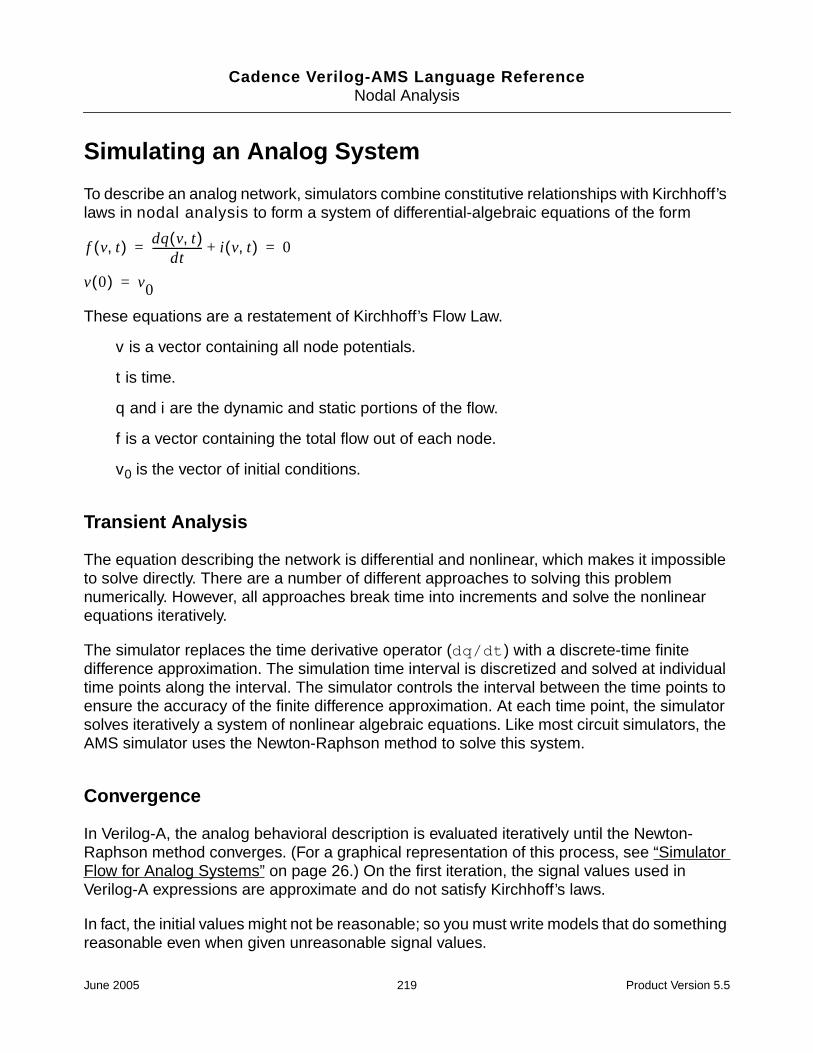
Cadence Verilog-AMS Language ReferenceNodal Analysis
Simulating an Analog System
To describe an analog network, simulators combine constitutive relationships with Kirchhoff’slaws in nodal analysis to form a system of differential-algebraic equations of the form
These equations are a restatement of Kirchhoff’s Flow Law.
v is a vector containing all node potentials.
t is time.
q and i are the dynamic and static portions of the flow.
f is a vector containing the total flow out of each node.
v0 is the vector of initial conditions.
Transient Analysis
The equation describing the network is differential and nonlinear, which makes it impossibleto solve directly. There are a number of different approaches to solving this problemnumerically. However, all approaches break time into increments and solve the nonlinearequations iteratively.
The simulator replaces the time derivative operator (dq/dt) with a discrete-time finitedifference approximation. The simulation time interval is discretized and solved at individualtime points along the interval. The simulator controls the interval between the time points toensure the accuracy of the finite difference approximation. At each time point, the simulatorsolves iteratively a system of nonlinear algebraic equations. Like most circuit simulators, theAMS simulator uses the Newton-Raphson method to solve this system.
Convergence
In Verilog-A, the analog behavioral description is evaluated iteratively until the Newton-Raphson method converges. (For a graphical representation of this process, see “SimulatorFlow for Analog Systems” on page 26.) On the first iteration, the signal values used inVerilog-A expressions are approximate and do not satisfy Kirchhoff’s laws.
In fact, the initial values might not be reasonable; so you must write models that do somethingreasonable even when given unreasonable signal values.
f v t,( ) dq v t,( )dt
------------------- i v t,( )+ 0= =
v 0( ) v0=
June 2005 219 Product Version 5.5

Cadence Verilog-AMS Language ReferenceNodal Analysis
For example, if you compute the log or square root of a signal value, some signal valuescause the arguments to these functions to become negative, even though a real-world systemnever exhibits negative values.
As the iteration progresses, the signal values approach the solution. Iteration continues untiltwo convergence criteria are satisfied. The first criterion is that the proposed solution on thisiteration, v(j)(t), must be close to the proposed solution on the previous iteration, v(j-1)(t), and
where reltol is the relative tolerance and abstol is the absolute tolerance.
reltol is set as a simulator option and typically has a value of 0.001. There can be manyabsolute tolerances, and which one is used depends on the resolved discipline of the net. Youset absolute tolerances by specifying the abstol attribute for the natures you use. Theabsolute tolerance is important when vn is converging to zero. Without abstol, the iterationnever converges.
The second criterion ensures that Kirchhoff’s Flow Law is satisfied:
where fni(v(j)) is the flow exiting node n from branch i.
Both of these criteria specify the absolute tolerance to ensure that convergence is notprecluded when vn or fn(v) go to zero. While you can set the relative tolerance once in anoptions statement in the analog simulation control file (.scs) to work effectively on any nodein the circuit, you must scale the absolute tolerance appropriately for the associatedbranches. Set the absolute tolerance to be the largest value that is negligible on all thebranches with which it is associated.
The simulator uses absolute tolerance to get an idea of the scale of signals. Absolutetolerances are typically 1,000 to 1,000,000 times smaller than the largest typical value forsignals of a particular quantity. For example, in a typical integrated circuit, the largest potentialis about 5 volts; so the default absolute tolerance for voltage is 1 µV. The largest current isabout 1 mA; so the default absolute tolerance for current is 1 pA.
vnj( )
vnj 1–( )
– reltol max vnj( )
vnj 1–( ),
abstol+<
f n v j( )( )n∑ reltol max f i
n v j( )( )( )( ) abstol+<
June 2005 220 Product Version 5.5

Cadence Verilog-AMS Language Reference
BAnalog Probes and Sources
This appendix describes what analog probes and sources are and gives some examples ofusing them. For information, see
■ Probes on page 222
■ Port Branches on page 222
■ Sources on page 223
For examples, see
■ Linear Conductor on page 227
■ Linear Resistor on page 227
■ RLC Circuit on page 227
■ Simple Implicit Diode on page 228
June 2005 221 Product Version 5.5

Cadence Verilog-AMS Language ReferenceAnalog Probes and Sources
Overview of Probes and Sources
A probe is a branch in which no value is assigned for either the potential or the flow, anywherein the module. A source is a branch in which either the potential or the flow is assigned avalue by a contribution statement somewhere in the module.
You might find it useful to describe component behavior as a network of probes and sources.
■ It is sometimes easier to describe a component first as a network of probes and sources,and then use the rules presented here to map the network into a behavioral description.
■ A complex behavioral description is sometimes easier to understand if it is converted intoa network of probes and sources.
The probe and source interpretation provides the additional benefit of unambiguouslydefining what the response will be when you manipulate a signal.
Probes
A flow probe is a branch in which the flow is used in an expression somewhere in the module.A potential probe is a branch in which the potential is used. You must not measure both thepotential and the flow of a probe branch.
The equivalent circuit model for a potential probe is
The branch flow of a potential probe is zero.
The equivalent circuit model for a flow probe is
The branch potential of a flow probe is zero.
Port Branches
You can use the port access function to monitor the flow into the port of a module. The nameof the access function is derived from the flow nature of the discipline of the port and you usethe (<>) operator to delimit the port name. For example, I(<a>) accesses the currentthrough module port a.
p
f
June 2005 222 Product Version 5.5

Cadence Verilog-AMS Language ReferenceAnalog Probes and Sources
A port branch, which is a special form of a flow probe, measures the flow into a port ratherthan across a branch. When a port is connected to numerous branches, using a port branchprovides a quick way of summing the flow.
The expression V(<a>) is invalid for ports and nets, where V is a potential access function.The port branch probe I(<a>) cannot be used on the left side of a contribution operator <+.As a result of these restrictions, you cannot use port branches to create behavioral resistors,capacitors, and inductors.
In the following example, the simulator issues a warning if the current through the diodebecomes too large.
module diode (a, c) ;electrical a, c ;branch (a, c) diode, cap ;parameter real is=1e-14, tf=0, cjo=0, imax=1, phi=0.7 ;
analog beginI(diode) <+ is*(limexp(V(diode)/$vt) – 1) ;I(cap) <+ ddt(tf*I(diode) - 2 * cjo * sqrt(phi * (phi * V(cap)))) ;if (I(<a>) > imax) // Checks current through port
$strobe( "Warning: diode is melting!" ) ;end
endmodule
Sources
A potential source is a branch in which the potential is assigned a value by a contributionstatement somewhere in the module. A flow source is a branch in which the flow is assigneda value. A branch cannot simultaneously be both a potential and a flow source, although itcan switch between the two kinds. For additional information, see “Switch Branches” onpage 225.
June 2005 223 Product Version 5.5

Cadence Verilog-AMS Language ReferenceAnalog Probes and Sources
The circuit model for a potential source branch shows that you can obtain both the flow andthe potential for a potential source branch.
Similarly, the circuit model for a flow source branch shows that you can obtain the flow andpotential for a flow source branch.
With the flow and potential sources, you can model the four basic controlled sources, usingnode or branch declarations and contribution statements like those in the following codefragments.
The model for a voltage-controlled voltage source is
branch (ps,ns) in, (p,n) out;V(out) <+ A * V(in);
The model for a voltage-controlled current source is
branch (ps,ns) in, (p,n) out;I(out) <+ A * V(in);
The model for a current-controlled voltage source is
branch (ps,ns) in, (p,n) out;V(out) <+ A * I(in);
Flow probe
Potentialsource
Potential probe
f
p
Flow probe
Flowsource
Potential probe
f
p
June 2005 224 Product Version 5.5

Cadence Verilog-AMS Language ReferenceAnalog Probes and Sources
The model for a current-controlled current source is
branch (ps,ns) in, (p,n) out;I(out) <+ A * I(in);
Unassigned Sources
If you do not assign a value to a branch, the branch flow, by default, is set to zero. In thefollowing fragment, for example, when closed is true, V(p,n) is set to zero. When closedis false, the current I(p,n) is set to zero.
if (closed)V(p,n) <+ 0 ;
elseI(p,n) <+ 0 ;
Alternatively, you could achieve the same result with
if (closed)V(p,n) <+ 0 ;
This code fragment also sets V(p,n) to zero when closed is true. When closed is false,the current is set to zero by default.
Switch Branches
Switch branches are branches that change from source potential branches into source flowbranches, and vice versa. Switch branches are useful when you want to model ideal switchesor mechanical stops.
To switch a branch to being a potential source, assign to its potential. To switch a branch tobeing a flow source, assign to its flow. The circuit model for a switch branch illustrates the
June 2005 225 Product Version 5.5

Cadence Verilog-AMS Language ReferenceAnalog Probes and Sources
effect, with the position of the switch dependent upon whether you assign to the potential orto the flow of the branch.
As an example of a switch branch, consider the module idealRelay.
module idealRelay (pout, nout, psense, nsense) ;input psense, nsense ;output pout, nout ;electrical pout, nout, psense, nsense ;parameter real thresh = 2.5 ;analog begin
if (V(psense, nsense) > thresh)V(pout, nout) <+ 0.0 ; // Becomes potential source
elseI(pout, nout) <+ 0.0 ; // Becomes flow source
endendmodule
The simulator assumes that a discontinuity of order zero occurs whenever the branchswitches; so you do not have to use the discontinuity function with switch branches. For moreinformation about the discontinuity function, see “Announcing Discontinuity” on page 105.
Examples of Sources and Probes
The following examples illustrate how to construct models using sources and probes.
Flow probe
Potentialsource
Potential probe
Flow source
f
p
June 2005 226 Product Version 5.5
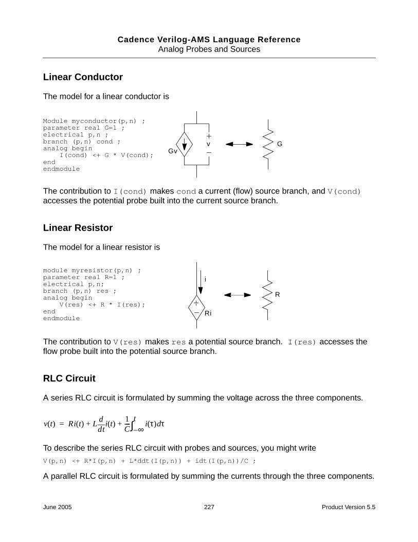
Cadence Verilog-AMS Language ReferenceAnalog Probes and Sources
Linear Conductor
The model for a linear conductor is
The contribution to I(cond) makes cond a current (flow) source branch, and V(cond)accesses the potential probe built into the current source branch.
Linear Resistor
The model for a linear resistor is
The contribution to V(res) makes res a potential source branch. I(res) accesses theflow probe built into the potential source branch.
RLC Circuit
A series RLC circuit is formulated by summing the voltage across the three components.
To describe the series RLC circuit with probes and sources, you might write
V(p,n) <+ R*I(p,n) + L*ddt(I(p,n)) + idt(I(p,n))/C ;
A parallel RLC circuit is formulated by summing the currents through the three components.
Module myconductor(p,n) ;parameter real G=1 ;electrical p,n ;branch (p,n) cond ;analog begin
I(cond) <+ G * V(cond);endendmodule
Gvv G
module myresistor(p,n) ;parameter real R=1 ;electrical p,n;branch (p,n) res ;analog begin
V(res) <+ R * I(res);endendmodule
i
Ri
R
v t( ) Ri t( ) Ltd
di t( )
1C---- i τ( ) τd
∞–t∫+ +=
June 2005 227 Product Version 5.5

Cadence Verilog-AMS Language ReferenceAnalog Probes and Sources
To describe the parallel RLC circuit, you might code
I(p,n) <+ V(p,n)/R + C*ddt(V(p,n)) + idt(V(p,n))/L ;
Simple Implicit Diode
This example illustrates a case where the model equation is implicit. The model equation isimplicit because the current I(a,c) appears on both sides of the contribution operator. Theequation specifies the current of the branch, making it a flow source branch. In addition, boththe voltage and the current of the branch are used in the behavioral description.
I(a,c) <+ is * (limexp((V(a,c) – rs * I(a,c)) / Vt) – 1) ;
i t( ) v t( )R
-------- Ctd
dv t( )
1L--- v τ( ) τd
∞–t∫++=
June 2005 228 Product Version 5.5

Cadence Verilog-AMS Language Reference
CStandard Definitions
The following definitions are included in the disciplines.vams and constants.vamsfiles, which are supplied with the Cadence® Verilog®-A language. To see the contents ofthese files, go to
■ disciplines.vams File on page 230
■ constants.vams File on page 234
You can use these definitions as they are, change them, or override them. For example, tooverride the default value of the abstol attribute of the nature current, defineCURRENT_ABSTOL before including the disciplines.vams file.
For information on how to include these definitions in your files, see “Including Files atCompilation Time” on page 213.
June 2005 229 Product Version 5.5

Cadence Verilog-AMS Language ReferenceStandard Definitions
disciplines.vams File`ifdef DISCIPLINES_VAMS`else`define DISCIPLINES_VAMS 1
//// Natures and Disciplines//
discipline logic domain discrete;enddiscipline
/* * Default absolute tolerances may be overridden by setting the * appropriate _ABSTOL prior to including this file */
// Electrical
// Current in amperesnature Current
units = “A”;access = I;idt_nature = Charge;
`ifdef CURRENT_ABSTOLabstol = `CURRENT_ABSTOL;
`elseabstol = 1e-12;
`endifendnature
// Charge in coulombsnature Charge
units = “coul”;access = Q;ddt_nature = Current;
`ifdef CHARGE_ABSTOLabstol = `CHARGE_ABSTOL;
`elseabstol = 1e-14;
`endifendnature
// Potential in voltsnature Voltage
units = “V”;access = V;idt_nature = Flux;
`ifdef VOLTAGE_ABSTOLabstol = `VOLTAGE_ABSTOL;
`elseabstol = 1e-6;
`endifendnature
// Flux in Webersnature Flux
units = “Wb”;access = Phi;ddt_nature = Voltage;
`ifdef FLUX_ABSTOLabstol = `FLUX_ABSTOL;
June 2005 230 Product Version 5.5

Cadence Verilog-AMS Language ReferenceStandard Definitions
`elseabstol = 1e-9;
`endifendnature
// Conservative disciplinediscipline electrical
potential Voltage;flow Current;
enddiscipline
// Signal flow disciplinesdiscipline voltage
potential Voltage;enddiscipline
discipline currentpotential Current;
enddiscipline
// Magnetic// Magnetomotive force in Ampere-Turns.nature Magneto_Motive_Force
units = “A*turn”;access = MMF;
`ifdef MAGNETO_MOTIVE_FORCE_ABSTOLabstol = `MAGNETO_MOTIVE_FORCE_ABSTOL;
`elseabstol = 1e-12;
`endifendnature
// Conservative disciplinediscipline magnetic
potential Magneto_Motive_Force;flow Flux;
enddiscipline
// Thermal
// Temperature in Celsiusnature Temperature
units = “C”;access = Temp;
`ifdef TEMPERATURE_ABSTOLabstol = `TEMPERATURE_ABSTOL;
`elseabstol = 1e-4;
`endifendnature
// Power in Wattsnature Power
units = “W”;access = Pwr;
`ifdef POWER_ABSTOLabstol = `POWER_ABSTOL;
`elseabstol = 1e-9;
`endifendnature
June 2005 231 Product Version 5.5

Cadence Verilog-AMS Language ReferenceStandard Definitions
// Conservative disciplinediscipline thermal
potential Temperature;flow Power;
enddiscipline
// Kinematic
// Position in metersnature Position
units = “m”;access = Pos;ddt_nature = Velocity;
`ifdef POSITION_ABSTOLabstol = `POSITION_ABSTOL;
`elseabstol = 1e-6;
`endifendnature
// Velocity in meters per secondnature Velocity
units = “m/s”;access = Vel;ddt_nature = Acceleration;idt_nature = Position;
`ifdef VELOCITY_ABSTOLabstol = `VELOCITY_ABSTOL;
`elseabstol = 1e-6;
`endifendnature
// Acceleration in meters per second squarednature Acceleration
units = “m/s^2”;access = Acc;ddt_nature = Impulse;idt_nature = Velocity;
`ifdef ACCELERATION_ABSTOLabstol = `ACCELERATION_ABSTOL;
`elseabstol = 1e-6;
`endifendnature
// Impulse in meters per second cubednature Impulse
units = “m/s^3”;access = Imp;idt_nature = Acceleration;
`ifdef IMPULSE_ABSTOLabstol = `IMPULSE_ABSTOL;
`elseabstol = 1e-6;
`endifendnature
// Force in newtonsnature Force
units = “N”;access = F;
`ifdef FORCE_ABSTOL
June 2005 232 Product Version 5.5

Cadence Verilog-AMS Language ReferenceStandard Definitions
abstol = `FORCE_ABSTOL;`else
abstol = 1e-6;`endifendnature
// Conservative disciplinesdiscipline kinematic
potential Position;flow Force;
enddiscipline
discipline kinematic_vpotential Velocity;flow Force;
enddiscipline
// Rotational
// Angle in radiansnature Angle
units = “rads”;access = Theta;ddt_nature = Angular_Velocity;
`ifdef ANGLE_ABSTOLabstol = `ANGLE_ABSTOL;
`elseabstol = 1e-6;
`endifendnature
// Angular Velocity in radians per secondnature Angular_Velocity
units = “rads/s”;access = Omega;ddt_nature = Angular_Acceleration;idt_nature = Angle;
`ifdef ANGULAR_VELOCITY_ABSTOLabstol = `ANGULAR_VELOCITY_ABSTOL;
`elseabstol = 1e-6;
`endifendnature
// Angular acceleration in radians per second squarednature Angular_Acceleration
units = “rads/s^2”;access = Alpha;idt_nature = Angular_Velocity;
`ifdef ANGULAR_ACCELERATION_ABSTOLabstol = `ANGULAR_ACCELERATION_ABSTOL;
`elseabstol = 1e-6;
`endifendnature
// Force in newtonsnature Angular_Force
units = “N*m”;access = Tau;
`ifdef ANGULAR_FORCE_ABSTOLabstol = `ANGULAR_FORCE_ABSTOL;
`elseabstol = 1e-6;
June 2005 233 Product Version 5.5

Cadence Verilog-AMS Language ReferenceStandard Definitions
`endifendnature
// Conservative disciplinesdiscipline rotational
potential Angle;flow Angular_Force;
enddiscipline
discipline rotational_omegapotential Angular_Velocity;flow Angular_Force;
enddiscipline
`endif
constants.vams File// Mathematical and physical constants
`ifdef CONSTANTS_VAMS`else`define CONSTANTS_VAMS 1
// M_ is a mathmatical constant
`define M_E 2.7182818284590452354`define M_LOG2E 1.4426950408889634074`define M_LOG10E 0.43429448190325182765`define M_LN2 0.69314718055994530942`define M_LN10 2.30258509299404568402`define M_PI 3.14159265358979323846`define M_TWO_PI 6.28318530717958647652`define M_PI_2 1.57079632679489661923`define M_PI_4 0.78539816339744830962`define M_1_PI 0.31830988618379067154`define M_2_PI 0.63661977236758134308`define M_2_SQRTPI 1.12837916709551257390`define M_SQRT2 1.41421356237309504880`define M_SQRT1_2 0.70710678118654752440
// P_ is a physical constant
// charge of electron in coulombs`define P_Q 1.6021918e-19
// speed of light in vacuum in meters/sec`define P_C 2.997924562e8
// Boltzmann's constant in joules/kelvin`define P_K 1.3806226e-23
// Planck's constant in joules*sec`define P_H 6.6260755e-34
// permittivity of vacuum in farads/meter`define P_EPS0 8.85418792394420013968e-12
// permeability of vacuum in henrys/meter`define P_U0 (4.0e-7 * `M_PI)
// zero celsius in kelvin`define P_CELSIUS0 273.15
`endif
June 2005 234 Product Version 5.5

Cadence Verilog-AMS Language Reference
DSample Model Library
This appendix discusses the Sample Model Library, which is included with this product. Thelibrary contains the following types of components:
■ Analog Components on page 237
■ Basic Components on page 254
■ Control Components on page 262
■ Logic Components on page 270
■ Electromagnetic Components on page 290
■ Functional Blocks on page 293
■ Magnetic Components on page 316
■ Mathematical Components on page 320
■ Measure Components on page 337
■ Mechanical Systems on page 357
■ Mixed-Signal Components on page 364
■ Power Electronics Components on page 373
■ Semiconductor Components on page 376
■ Telecommunications Components on page 384
You can use these models as they are, you can copy them and modify them to create newparts, or you can use them as examples. The models are in the following directory in thesoftware hierarchy:
Refer to the README file in this directory for a list of the files containing the models. Thefilenames have the suffix .. For example, the model for the switch is located in sw.. Eachmodel has an associated test circuit that can be used to simulate the model.
June 2005 235 Product Version 5.5

Cadence Verilog-AMS Language ReferenceSample Model Library
These models are also integrated into a Cadence® design framework II library, complete withsymbols and Component Description Formats (CDFs). If you are using the Cadence analogdesign environment, you can access these models by adding the following library to yourlibrary path:
your_install_dir/tools/dfII/samples/artist/ahdlLib
This appendix provides a list of the parts and functions in the sample library. They aregrouped according to application.
In the terminal description and parameter descriptions, the letters between the squarebrackets, such as [V,A] and [V], refer to the units associated with the terminal or parameter.V means volts, A means amps. (val, flow) means that any units can be used.
June 2005 236 Product Version 5.5

Cadence Verilog-AMS Language ReferenceSample Model Library
Analog Components
Analog Multiplexer
Terminals
vin1, vin2: [V,A]
vsel: selection voltage [V,A]
vout: [V,A]
Description
When vsel > vth, the output voltage follows vin1.
When vsel < vth, the output voltage follows vin2.
Instance Parameters
vth = 1->0 threshold voltage for the selection line [V]
June 2005 237 Product Version 5.5

Cadence Verilog-AMS Language ReferenceSample Model Library
Current Deadband Amplifier
Terminals
iin_p, iin_n: differential input current terminals [V,A]
iout: output current terminal [V,A]
Description
Outputs ileak when differential input current (iin_p - iin_n) is between idead_low andidead_high. When outside the deadband, the output current is an amplified version of thedifferential input current plus ileak.
Instance Parameters
idead_low = lower range of dead band [A]
idead_high = upper range of dead band [A]
ileak = offset current; only output in deadband [A]
gain_low = differential current gain in lower region []
gain_high = differential current gain in lower region []
June 2005 238 Product Version 5.5

Cadence Verilog-AMS Language ReferenceSample Model Library
Hard Current Clamp
Terminals
vin: input terminal [V,A]
vout: output terminal [V,A]
vgnd: gnd terminal [V,A]
Description
Hard limits output current to between iclamp_upper and iclamp_lower of the inputcurrent.
Instance Parameters
iclamp_upper = upper clamping current [A]
iclamp_lower = lower clamping current [A]
June 2005 239 Product Version 5.5

Cadence Verilog-AMS Language ReferenceSample Model Library
Hard Voltage Clamp
Terminals
vin: input terminal [V,A]
vout: output terminal [V,A]
vgnd: gnd terminal [V,A]
Description
vout- vgnd hard clamped/limited to between vclamp_upper and vclamp_lower of vin -vgnd.
Instance Parameters
vclamp_upper = upper clamping voltage [A]
vclamp_lower = lower clamping voltage [A]
June 2005 240 Product Version 5.5

Cadence Verilog-AMS Language ReferenceSample Model Library
Open Circuit Fault
Terminals
vp, vn: output terminals [V,A]
Description
At time=twait, the connection between the two terminals is opened. Before this, theconnection between the terminals is closed.
Instance Parameters
twait = time to wait before open fault happens [s]
June 2005 241 Product Version 5.5

Cadence Verilog-AMS Language ReferenceSample Model Library
Operational Amplifier
Terminals
vin_p, vin_n: differential input voltage [V,A]
vout: output voltage [V,A]
vref: reference voltage [V,A]
vspply_p: positive supply voltage [V,A]
vspply_n: negative supply voltage [V,A]
Instance Parameters
gain = gain []
freq_unitygain = unity gain frequency [Hz]
rin = input resistance [Ohms]
vin_offset = input offset voltage referred to negative [V]
ibias = input current [A]
iin_max = maximum current [A]
rsrc = source resistance [Ohms]
rout = output resistance [Ohms]
vsoft = soft output limiting value [V]
June 2005 242 Product Version 5.5

Cadence Verilog-AMS Language ReferenceSample Model Library
Constant Power Sink
Terminals
vp, vn: terminals [V,A]
Description
Normally power watts of power is sunk. If the absolute value of vp - vn is above vabsmin,a faction of the power is sunk. The fraction is the ratio of vp - vn to vabsmin.
Instance Parameters
power = power sunk [Watts]
vabsmin = absolute value of minimum input voltage [V]
June 2005 243 Product Version 5.5

Cadence Verilog-AMS Language ReferenceSample Model Library
Short Circuit Fault
Terminals
vp, vn: output terminals [V,A]
Description
At time=twait, the two terminals short. Before this, the connection between the terminals isopen.
Instance Parameters
twait = time to wait before short circuit occurs [s]
June 2005 244 Product Version 5.5

Cadence Verilog-AMS Language ReferenceSample Model Library
Soft Current Clamp
Terminals
vin: input terminal [V,A]
vout: output terminal [V,A]
vgnd: gnd terminal [V,A]
Description
Limits output current to between iclamp_upper and iclamp_lower of the input current.
The limiting starts working once the input current gets near iclamp_lower oriclamp_upper. The clamping acts exponentially to ensure smoothness.
The fraction of the range (iclamp_lower, iclamp_upper) over which the exponentialclamping action occurs is exp_frac.
Excess current coming from vin is routed to vgnd.
Instance Parameters
iclamp_upper = upper clamping current [A]
iclamp_lower = lower clamping current [A]
exp_frac = fraction of iclamp range from iclamp_upper and iclamp_lower at whichexponential clamping starts to have an effect []
June 2005 245 Product Version 5.5

Cadence Verilog-AMS Language ReferenceSample Model Library
Soft Voltage Clamp
Terminals
vin: input terminal [V,A]
vout: output terminal [V,A]
vgnd: gnd terminal [V,A]
Description
vout- vgnd clamped/limited to between vclamp_upper and vclamp_lower of vin -vgnd.
The limiting starts working once the input voltage gets near vclamp_lower orvclamp_upper. The clamping acts exponentially to ensure smoothness.
The fraction of the range (vclamp_lower, vclamp_upper) over which the exponentialclamping action occurs is exp_frac.
Instance Parameters
vclamp_upper = upper clamping voltage [A]
vclamp_lower = lower clamping voltage [A]
exp_frac = fraction of vclamp range from vclamp_upper and vclamp_lower at whichexponential clamping starts to have an effect []
June 2005 246 Product Version 5.5

Cadence Verilog-AMS Language ReferenceSample Model Library
Self-Tuning Resistor
Terminals
vp, vn: terminals [V,A]
vtune: the voltage that is being tuned [V,A]
verr: the error in vtune [V,A]
Description
This element operates in four distinct phases:
1. It waits for tsettle seconds with the resistance between vp and vn set to rinit.
2. For tdir_check seconds, it attempts to tune the error away by increasing theresistance in proportion to the size of the error.
3. It waits for tsettle seconds with the resistance between vp and vn set to rinit.
4. For tdir_check seconds, it attempts to tune the error away by decreasing theresistance in proportion to the error.
5. Based on the results of (2) and (4), it selects which direction is better to tune in and tunesas best it can using integral action. For certain systems, this might lead to unstablebehavior.
Note: Select tsettle to be greater than the largest system time constant. Select rgain sothat the positive feedback is not excessive during the direction sensing phases. Selecttdir_check so that the system has enough time to react but not so big that the resistancedrifts too far from rinit. It is better if it can be arranged that verr does not change signduring tuning.
Instance Parameters
rmax = maximum resistance that tuning res can have [Ohms]
rmin = minimum resistance that tuning res can have [Ohms]
rinit = initial resistance [Ohms]
rgain = gain of integral tuning action [Ohms/(Vs)]
June 2005 247 Product Version 5.5

Cadence Verilog-AMS Language ReferenceSample Model Library
vtune_set = value that vtune must be tuned to [V]
tsettle = amount of time to wait before tuning begins [s]
tdir_check = amount of time to spend checking each tuning direction [s]
June 2005 248 Product Version 5.5

Cadence Verilog-AMS Language ReferenceSample Model Library
Untrimmed Capacitor
Terminals
vp, vn: terminals [V,A]
Description
Each instance has a randomly generated value of capacitance, which is calculated atinitialization. The distribution of these random values is gaussian (that is, normal) with ac_mean and a standard deviation of c_std.
Two seeds are needed to generate the gaussian distribution.
Instance Parameters
c_mean = mean capacitance [Ohms]
c_dev = standard deviation of capacitance [Ohms]
seed1 = first seed value for randomly generating capacitance values []
seed2 = second seed value for randomly generating capacitance values []
show_val = option to print the value of capacitance to stdout
June 2005 249 Product Version 5.5
Cadence Verilog-AMS Language ReferenceSample Model Library
Untrimmed Inductor
Terminals
vp, vn: terminals [V,A]
Description
Each instance has a randomly generated value of inductance, which is calculated atinitialization. The distribution of these random values is gaussian (that is, normal) with anl_mean and a standard deviation of l_std.
Two seeds are needed to generate the gaussian distribution.
Instance Parameters
l_mean = mean inductance [Ohms]
l_dev = standard deviation of inductance [Ohms]
seed1 = first seed value for randomly generating inductance values []
seed2 = second seed value for randomly generating inductance values []
show_val = option to print the value of inductance to stdout
June 2005 250 Product Version 5.5

Cadence Verilog-AMS Language ReferenceSample Model Library
Untrimmed Resistor
Terminals
vp, vn: terminals [V,A]
Description
Each instance has a randomly generated value of resistance, which is calculated atinitialization. The distribution of these random values is gaussian (that is, normal) with anr_mean and a standard deviation of r_std.
Two seeds are needed to generate the gaussian distribution.
Instance Parameters
r_mean = mean resistance [Ohms]
r_dev = standard deviation of resistance [Ohms]
seed1 = first seed value for randomly generating resistance values []
seed2 = second seed value for randomly generating resistance values []
show_val = option to print the value of resistance to stdout
June 2005 251 Product Version 5.5
Cadence Verilog-AMS Language ReferenceSample Model Library
Voltage Deadband Amplifier
Terminals
vin_p, vin_n: differential input voltage terminals [V,A]
vout: output voltage terminal [V,A]
Description
Outputs vleak when differential input voltage (vin_p-vin_n) is between vdead_low andvdead_high. When outside the deadband, the output voltage is an amplified version of thedifferential input voltage plus vleak.
Instance Parameters
vdead_low = lower range of dead band [V]
vdead_high = upper range of dead band [V]
vleak = offset voltage; only output in deadband [V]
gain_low = differential voltage gain in lower region []
gain_high = differential voltage gain in upper region []
June 2005 252 Product Version 5.5

Cadence Verilog-AMS Language ReferenceSample Model Library
Voltage-Controlled Variable-Gain Amplifier
Terminals
vin_p, vin_n: differential input terminals [V,A]
vctrl_p, vctrl_n: differential-controlling voltage terminals [V,A]
vout: [V,A]
Description
When there is no input offset voltage, the output is vout = gain_const * (vctrl_p -vctrl_n) * (vin_p - vin_n) + (vout_high + vout_low)/2.
When there is an input offset voltage, vin_offset is subtracted from (vin_p - vin_n).
Instance Parameters
gain_const = amplifier gain when (vctrl_p - vctrl_n) = 1 volt []
vout_high = upper output limit [V]
vout_low = lower output limit [V]
vin_offset = input offset [V]
June 2005 253 Product Version 5.5

Cadence Verilog-AMS Language ReferenceSample Model Library
Basic Components
Resistor
Terminals
vp, vn: terminals (V,A)
Instance Parameters
r = resistance (Ohms)
June 2005 254 Product Version 5.5

Cadence Verilog-AMS Language ReferenceSample Model Library
Capacitor
Terminals
vp, vn: terminals (V,A)
Instance Parameters
c = capacitance (F)
June 2005 255 Product Version 5.5

Cadence Verilog-AMS Language ReferenceSample Model Library
Inductor
Terminals
vp, vn: terminals (V,A)
Instance Parameters
l = inductance (H)
June 2005 256 Product Version 5.5

Cadence Verilog-AMS Language ReferenceSample Model Library
Voltage-Controlled Voltage Source
Terminals
vout_p, vout_n: controlled voltage terminals [V,A]
vin_p, vin_n: controlling voltage terminals [V,A]
Instance Parameters
gain = voltage gain []
June 2005 257 Product Version 5.5

Cadence Verilog-AMS Language ReferenceSample Model Library
Current-Controlled Voltage Source
Terminals
vout_p, vout_n: controlled voltage terminals [V,A]
iin_p, iin_n: controlling current terminals [V,A]
Instance Parameters
rm = resistance multiplier (V to I gain) [Ohms]
June 2005 258 Product Version 5.5

Cadence Verilog-AMS Language ReferenceSample Model Library
Voltage-Controlled Current Source
Terminals
iout_p, iout_n: controlled current source terminals [V,A]
vin_p, vin_n: controlling voltage terminals [V,A]
Instance Parameters
gm = conductance multiplier (V to I gain) [Mhos]
June 2005 259 Product Version 5.5
Cadence Verilog-AMS Language ReferenceSample Model Library
Current-Controlled Current Source
Terminals
iout_p, iout_n: controlled current terminals [V,A]
iin_p, iin_n: controlling current terminals [V,A]
Instance Parameters
gain = current gain []
June 2005 260 Product Version 5.5

Cadence Verilog-AMS Language ReferenceSample Model Library
Switch
Terminals
vp, vn: output terminals [V,A]
vctrlp, vctrln: control terminals [V,A]
Description
If (vctrlp - vctrln > vth), the branch between vp and vn is shorted. Otherwise, thebranch between vp and vn is opened.
Instance Parameters
vth = threshold voltage [V]
June 2005 261 Product Version 5.5

Cadence Verilog-AMS Language ReferenceSample Model Library
Control Components
Error Calculation Block
Terminals
sigset: setpoint signal (val, flow)
sigact: actual value signal (val, flow)
sigerr: error: difference between signals (val, flow)
Description
sigerr = sigset - sigact
Note: Defining larger values of abstol and huge for the quantities associated with siginand sigout can help overcome convergence and clipping problems.
Instance Parameters
tdel, trise, tfall = {usual}
June 2005 262 Product Version 5.5

Cadence Verilog-AMS Language ReferenceSample Model Library
Lag Compensator
Terminals
sigin: (val, flow)
sigout: (val, flow)
Description
Note: Defining larger values of abstol and huge for the quantities associated with siginand sigout can help overcome convergence and clipping problems.
Instance Parameters
gain = compensator gain []
tau = compensator zero at -(1/tau) [s]
alpha = compensator pole at -(1/(alpha*tau)); alpha > 1 []
TF gain alpha× 1 tau S×+1 alpha tau× S×+------------------------------------------------×=
June 2005 263 Product Version 5.5

Cadence Verilog-AMS Language ReferenceSample Model Library
Lead Compensator
Terminals
sigin: (val, flow)
sigout: (val, flow)
Description
Note: Defining larger values of abstol and huge for the quantities associated with siginand sigout can help overcome convergence and clipping problems.
Instance Parameters
gain = compensator gain []
tau = compensator zero at -(1/tau) [s]
alpha = compensator pole at -(1/(alpha*tau)); alpha < 1 []
TF gain alpha× 1 tau S×+1 alpha tau× S×+------------------------------------------------×=
June 2005 264 Product Version 5.5

Cadence Verilog-AMS Language ReferenceSample Model Library
Lead-Lag Compensator
Terminals
sigin: (val, flow)
sigout: (val, flow)
Description
Defining larger values of abstol and huge for the quantities associated with sigin andsigout can help overcome convergence and clipping problems.
Instance Parameters
gain = compensator gain []
tau1 = compensator zero at -(1/tau1) [s]
alpha1 = compensator pole at -(1/(alpha*tau1)); alpha1 > 1 []
tau2 = compensator zero at -(1/tau2) [s]
alpha2 = compensator pole at -(1/(alpha*tau2)); alpha2 < 1 []
TF
gain alpha1× 1 tau1 S×+1 alpha1 tau1× S×+------------------------------------------------------- alpha2
1 tau2 S×+1 alpha2 tau2× S×+-------------------------------------------------------×××
=
June 2005 265 Product Version 5.5

Cadence Verilog-AMS Language ReferenceSample Model Library
Proportional Controller
Terminals
sigin: (val, flow)
sigout: (val, flow)
Description
sigout = kp*sigin
Note: Defining larger values of abstol and huge for the quantities associated with siginand sigout can help overcome convergence and clipping problems.
Instance Parameters
kp = proportional gain []
June 2005 266 Product Version 5.5

Cadence Verilog-AMS Language ReferenceSample Model Library
Proportional Derivative Controller
Terminals
sigin: (val, flow)
sigout: (val, flow)
Description
sigout = kp*sigin + kd* dot (sigin)
Note: Defining larger values of abstol and huge for the quantities associated with siginand sigout can help overcome convergence and clipping problems.
Instance Parameters
kp = proportional gain []
kd = differential gain []
June 2005 267 Product Version 5.5

Cadence Verilog-AMS Language ReferenceSample Model Library
Proportional Integral Controller
Terminals
sigin: (val, flow)
sigout: (val, flow)
Description
This model is a proportional, integral, and derivative controller.
sigout = kp * sigin + ki * integ (sigin) + kd* dot (sigin)
Note: Defining larger values of abstol and huge for the quantities associated with siginand sigout can help overcome convergence and clipping problems.
Instance Parameters
kp = proportional gain []
ki = integral gain []
June 2005 268 Product Version 5.5

Cadence Verilog-AMS Language ReferenceSample Model Library
Proportional Integral Derivative Controller
Terminals
sigin: (val, flow)
sigout: (val, flow)
Description
sigout = kp * sigin + ki * integ (sigin) + kd* dot (sigin)
Note: Defining larger values of abstol and huge for the quantities associated with siginand sigout can help overcome convergence and clipping problems.
Instance Parameters
kp = proportional gain []
ki = integral gain []
kd = differential gain []
June 2005 269 Product Version 5.5

Cadence Verilog-AMS Language ReferenceSample Model Library
Logic Components
AND Gate
Terminals
vin1, vin2: [V,A]
vout: [V,A]
Instance Parameters
vlogic_high = output voltage for high [V]
vlogic_low = output voltage for low [V]
vtrans = voltages above this at input are considered high [V]
tdel, trise, tfall = {usual} [s]
June 2005 270 Product Version 5.5
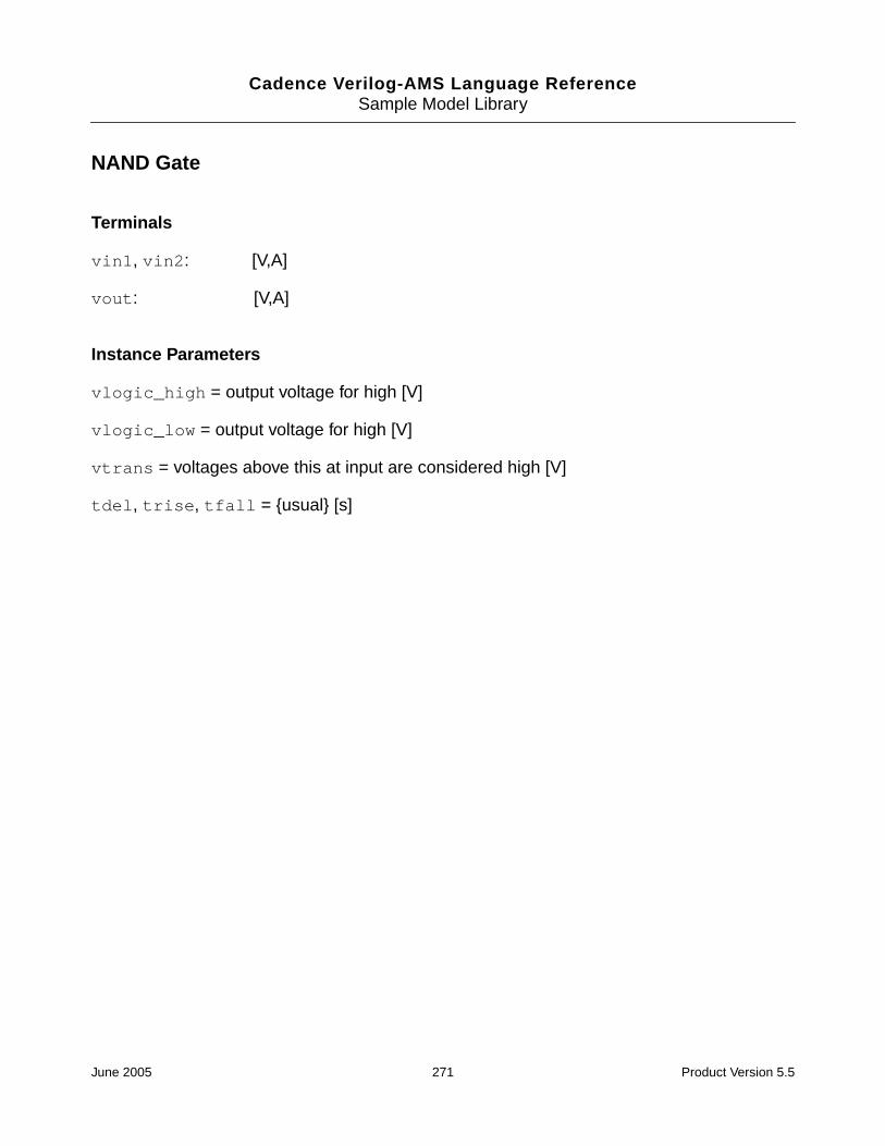
Cadence Verilog-AMS Language ReferenceSample Model Library
NAND Gate
Terminals
vin1, vin2: [V,A]
vout: [V,A]
Instance Parameters
vlogic_high = output voltage for high [V]
vlogic_low = output voltage for high [V]
vtrans = voltages above this at input are considered high [V]
tdel, trise, tfall = {usual} [s]
June 2005 271 Product Version 5.5

Cadence Verilog-AMS Language ReferenceSample Model Library
OR Gate
Terminals
vin1, vin2: [V,A]
vout: [V,A]
Instance Parameters
vlogic_high = output voltage for high [V]
vlogic_low = output voltage for high [V]
vtrans = voltages above this at input are considered high [V]
tdel, trise, tfall = {usual} [s]
June 2005 272 Product Version 5.5

Cadence Verilog-AMS Language ReferenceSample Model Library
NOT Gate
Terminals
vin: [V,A]
vout: [V,A]
Instance Parameters
vlogic_high = output voltage for high [V]
vlogic_low = output voltage for high [V]
vtrans = voltages above this at input are considered high [V]
tdel, trise, tfall = {usual} [s]
June 2005 273 Product Version 5.5

Cadence Verilog-AMS Language ReferenceSample Model Library
NOR Gate
Terminals
vin1, vin2: [V,A]
vout: [V,A]
Instance Parameters
vlogic_high = output voltage for high [V]
vlogic_low = output voltage for high [V]
vtrans = voltages above this at input are considered high [V]
tdel, trise, tfall = {usual} [s]
June 2005 274 Product Version 5.5

Cadence Verilog-AMS Language ReferenceSample Model Library
XOR Gate
Terminals
vin1, vin2: [V,A]
vout: [V,A]
Instance Parameters
vlogic_high = output voltage for high [V]
vlogic_low = output voltage for high [V]
vtrans = voltages above this at input are considered high [V]
tdel, trise, tfall = {usual} [s]
June 2005 275 Product Version 5.5

Cadence Verilog-AMS Language ReferenceSample Model Library
XNOR Gate
Terminals
vin1, vin2: [V,A]
vout: [V,A]
Instance Parameters
vlogic_high = output voltage for high [V]
vlogic_low = output voltage for high [V]
vtrans = voltages above this at input are considered high [V]
tdel, trise, tfall = {usual} [s]
June 2005 276 Product Version 5.5

Cadence Verilog-AMS Language ReferenceSample Model Library
D-Type Flip-Flop
Terminals
vin_d: [V,A]
vclk: [V,A]
out_q, vout_qbar: [V,A]
Description
Triggered on the rising edge.
Instance Parameters
vlogic_high = output voltage for high [V]
vlogic_low = output voltage for low [V]
vtrans = voltages above this at input are considered high [V]
vtrans_clk = transition voltage of clock [V]
tdel, trise, tfall = {usual} [s]
June 2005 277 Product Version 5.5
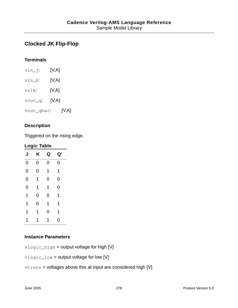
Cadence Verilog-AMS Language ReferenceSample Model Library
Clocked JK Flip-Flop
Terminals
vin_j: [V,A]
vin_k: [V,A]
vclk: [V,A]
vout_q: [V,A]
vout_qbar: [V,A]
Description
Triggered on the rising edge.
Logic Table
Instance Parameters
vlogic_high = output voltage for high [V]
vlogic_low = output voltage for low [V]
vtrans = voltages above this at input are considered high [V]
J K Q Q'
0 0 0 0
0 0 1 1
0 1 0 0
0 1 1 0
1 0 0 1
1 0 1 1
1 1 0 1
1 1 1 0
June 2005 278 Product Version 5.5

Cadence Verilog-AMS Language ReferenceSample Model Library
tdel, trise, tfall = {usual} [s]
June 2005 279 Product Version 5.5

Cadence Verilog-AMS Language ReferenceSample Model Library
JK-Type Flip-Flop
Terminals
vin_j, vin_k: inputs
vout_q, vout_qbar: outputs
Description
Triggered on the rising edge.
Logic Table
Instance Parameters
vlogic_high = output voltage for high [V]
vlogic_low = output voltage for low [V]
vtrans = voltages above this at input are considered high [V]
tdel, trise, tfall = {usual} [s]
J K Q Q(t+e)
0 0 0 0
0 0 1 1
0 1 0 0
0 1 1 0
1 0 0 1
1 0 1 1
1 1 0 1
1 1 1 0
June 2005 280 Product Version 5.5

Cadence Verilog-AMS Language ReferenceSample Model Library
Level Shifter
Terminals
sigin: (val, flow)
sigout: (val, flow)
Description
sigout = sigin added to sigshift.
Instance Parameters
sigshift = level shift (val)
June 2005 281 Product Version 5.5
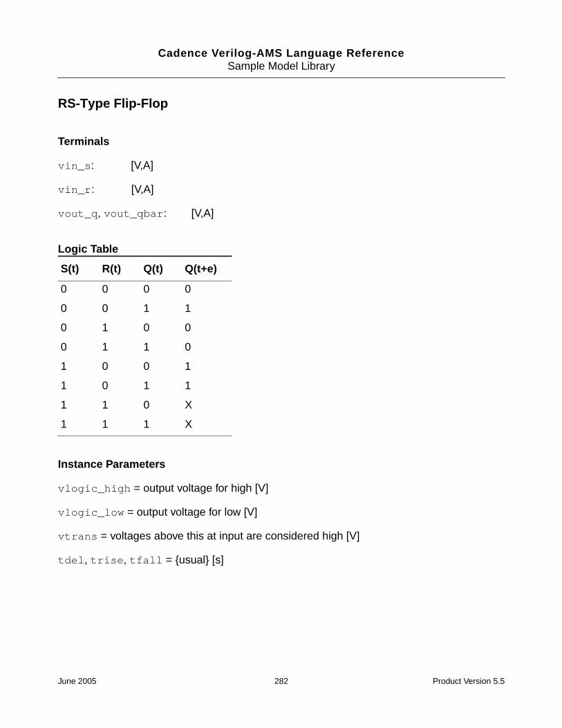
Cadence Verilog-AMS Language ReferenceSample Model Library
RS-Type Flip-Flop
Terminals
vin_s: [V,A]
vin_r: [V,A]
vout_q, vout_qbar: [V,A]
Logic Table
Instance Parameters
vlogic_high = output voltage for high [V]
vlogic_low = output voltage for low [V]
vtrans = voltages above this at input are considered high [V]
tdel, trise, tfall = {usual} [s]
S(t) R(t) Q(t) Q(t+e)
0 0 0 0
0 0 1 1
0 1 0 0
0 1 1 0
1 0 0 1
1 0 1 1
1 1 0 X
1 1 1 X
June 2005 282 Product Version 5.5

Cadence Verilog-AMS Language ReferenceSample Model Library
Trigger-Type (Toggle-Type) Flip-Flop
Terminals
vtrig: trigger [V,A]
vout_q, vout_qbar: outputs [V,A]
Description
Triggered on the rising edge.
Logic Table
Instance Parameters
initial_state = the initial state/output of the flip-flop []
vlogic_high = output voltage for high [V]
vlogic_low = output voltage for low [V]
vtrans = voltages above this at input are considered high [V]
tdel, trise, tfall = {usual} [s]
T Q Q(t+e)
0 0 0
0 1 1
1 0 1
1 1 0
June 2005 283 Product Version 5.5

Cadence Verilog-AMS Language ReferenceSample Model Library
Half Adder
Terminals
vin1, vin2: bits to be added [V,A]
vout_sum: vout_sum out [V,A]
vout_carry: carry out [V,A]
Instance Parameters
vlogic_high = logic high value [V]
vlogic_low = logic low value [V]
vtrans = threshold for inputs to be high [V]
tdel, trise, tfall = {usual} [s]
June 2005 284 Product Version 5.5

Cadence Verilog-AMS Language ReferenceSample Model Library
Full Adder
Terminals
vin1, vin2: bits to be added [V,A]
vin_carry: carry in [V,A]
vout_sum: sum out [V,A]
vout_carry: carry out [V,A]
Instance Parameters
vlogic_high = logic high value [V]
vlogic_low = logic low value [V]
vtrans = threshold for inputs to be high [V]
tdel, trise, tfall = {usual} [s]
June 2005 285 Product Version 5.5

Cadence Verilog-AMS Language ReferenceSample Model Library
Half Subtractor
Terminals
vin1, vin2: inputs [V,A]
vout_diff: difference out [V,A]
vout_borrow: borrow out [V,A]
Formula
vin1 - vin2 = vout_diff and borrow
Truth Table
Instance Parameters
vlogic_high = logic high value [V]
vlogic_low = logic low value [V]
vtrans = threshold for inputs to be high [V]
tdel, trise, tfall = {usual} [s]
in1 in2 diff borrow
0 0 0 0
0 1 1 1
1 0 1 0
1 1 0 0
June 2005 286 Product Version 5.5

Cadence Verilog-AMS Language ReferenceSample Model Library
Full Subtractor
Terminals
vin1, vin2: inputs [V,A]
vin_borrow: borrow in [V,A]
vout_diff: difference out [V,A]
vout_borrow: borrow out [V,A]
Truth Table
Instance Parameters
vlogic_high = logic high value [V]
vlogic_low = logic low value [V]
vtrans = threshold for inputs to be high [V]
tdel, trise, tfall = {usual} [s]
in1 in2 bin bout doff
0 0 0 0 0
0 0 1 1 1
0 1 0 1 1
0 1 1 1 0
1 0 0 0 1
1 0 1 0 0
1 1 0 0 0
1 1 1 1 1
June 2005 287 Product Version 5.5

Cadence Verilog-AMS Language ReferenceSample Model Library
Parallel Register, 8-Bit
Terminals
vin_d0..vin_d7: input data lines [V,A]
vout_d0..vout_d7: output data lines [V,A]
venable: enable line [V,A]
Description
Input occurs on the rising edge of venable.
Instance Parameters
vlogic_high = output voltage for high [V]
vlogic_low = output voltage for low [V]
vtrans = voltages above this at input are considered high [V]
tdel, trise, tfall = {usual} [s]
June 2005 288 Product Version 5.5

Cadence Verilog-AMS Language ReferenceSample Model Library
Serial Register, 8-Bit
Terminals
vin_d: input data lines [V,A]
vout_d: output data lines [V,A]
vclk: enable line [V,A]
Description
Input occurs on the rising edge of vclk.
Instance Parameters
vlogic_high = output voltage for high [V]
vlogic_low = output voltage for low [V]
vtrans = voltages above this at input are considered high [V]
tdel, trise, tfall = {usual} [s]
June 2005 289 Product Version 5.5

Cadence Verilog-AMS Language ReferenceSample Model Library
Electromagnetic Components
DC Motor
Terminals
vp: positive terminal [V,A]
vn: negative terminal [V,A]
pos_shaft: motor shaft [rad, Nm]
Description
This is a model of a DC motor driving a shaft.
Instance Parameters
km = motor constant [Vs/rad]
kf = flux constant [Nm/A]
j = inertia factor [Nms2/rad]
d = drag (friction) [Nms/rad]
rm = motor resistance [Ohms]
lm = motor inductance [H]
June 2005 290 Product Version 5.5

Cadence Verilog-AMS Language ReferenceSample Model Library
Electromagnetic Relay
Terminals
vopen: normally opened terminal [V,A]
vcomm: common terminal [V,A]
vclosed: normally closed terminal [V,A]
vctrl_n: negative control signal [V,A]
vctrl_p: positive control signal [V,A]
Description
This is a model of a voltage-controlled single-pole, double-throw switch. When the voltagedifferential between vctrl_p and vctrl_n exceeds vtrig, the normally open branch isshorted (closed). Otherwise, the normally open branch stays open. If the open branch isalready closed and the voltage differential between vctrl_p and vctrl_n falls belowvrelease, the normally open branch is opened.
Instance Parameters
vtrig = input value to close relay [V]
vrelease = input value to open relay [V]
June 2005 291 Product Version 5.5
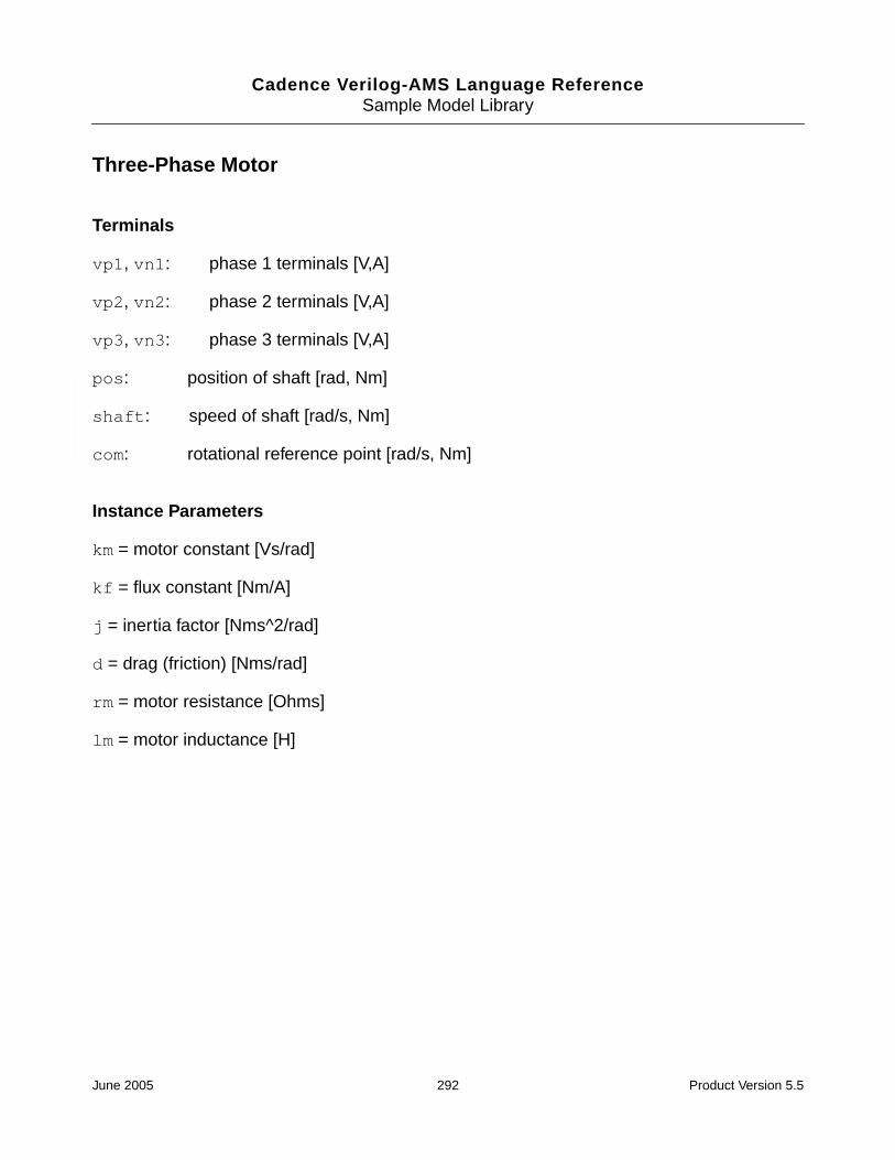
Cadence Verilog-AMS Language ReferenceSample Model Library
Three-Phase Motor
Terminals
vp1, vn1: phase 1 terminals [V,A]
vp2, vn2: phase 2 terminals [V,A]
vp3, vn3: phase 3 terminals [V,A]
pos: position of shaft [rad, Nm]
shaft: speed of shaft [rad/s, Nm]
com: rotational reference point [rad/s, Nm]
Instance Parameters
km = motor constant [Vs/rad]
kf = flux constant [Nm/A]
j = inertia factor [Nms^2/rad]
d = drag (friction) [Nms/rad]
rm = motor resistance [Ohms]
lm = motor inductance [H]
June 2005 292 Product Version 5.5
Cadence Verilog-AMS Language ReferenceSample Model Library
Functional Blocks
Amplifier
Terminals
sigin: input (val, flow)
sigout: output (val, flow)
Instance Parameters
gain = gain between input and output []
sigin_offset = subtracted from sigin before amplification (val)
June 2005 293 Product Version 5.5

Cadence Verilog-AMS Language ReferenceSample Model Library
Comparator
Terminals
sigin: (val, flow)
sigref: reference to which sigin is compared (val, flow)
sigout: comparator output (val, flow)
Description
Compares (sigin-sigin_offset) to sigref—the output is related to their difference bya tanh relationship.
If the difference >>> sigref, sigout is sigout_high.
If the difference = sigref, sigout is (sigout_high + sigout_low)/2.
If the difference <<< sigref, sigout is sigout_low.
Intermediate points are fitting to a tanh scaled by comp_slope.
Instance Parameters
sigout_high = maximum output of the comparator (val)
sigout_low = minimum output of the comparator (val)
sigin_offset = subtracted from sigin before comparison to sigref (val)
comp_slope = determines the sensitivity of the comparator []
June 2005 294 Product Version 5.5

Cadence Verilog-AMS Language ReferenceSample Model Library
Controlled Integrator
Terminals
sigin: (val, flow)
sigout: (val, flow)
sigctrl: (val, flow)
Description
Integration occurs while sigctrl is above sigctrl_trans.
Instance Parameters
sigout0 = initial sigout value (val)
gain = gain []
sigctrl_trans = if sigcntl is above this, integration occurs (val)
June 2005 295 Product Version 5.5

Cadence Verilog-AMS Language ReferenceSample Model Library
Deadband
Terminals
sigin: input (val, flow)
sigout: output (val, flow)
Description
Deadband region is when sigin is between sigin_dead_high and sigin_dead_low.sigout is zero in the deadband region. Above the deadband, the output is sigin -sigin_dead_high. Below the deadband, the output is sigin - sigin_dead_low.
Instance Parameters
sigin_dead_high = upper deadband limit (val)
sigin_dead_low = lower deadband limit (val)
June 2005 296 Product Version 5.5
Cadence Verilog-AMS Language ReferenceSample Model Library
Deadband Differential Amplifier
Terminals
sigin_p, sigin_n: differential input terminals (val, flow)
sigout: output terminal (val, flow)
Description
Outputs sigout_leak when differential input (sigin_p-sigin_n) is betweensigin_dead_low and sigin_dead_high. When outside the deadband, the output is anamplified version of the differential input plus sigout_leak.
Instance Parameters
sigin_dead_low = lower range of dead band (val)
sigin_dead_high = upper range of dead band (val)
sigout_leak = offset signal; only output in deadband (val)
gain_low = differential gain in lower region []
gain_high = differential gain in upper region []
June 2005 297 Product Version 5.5

Cadence Verilog-AMS Language ReferenceSample Model Library
Differential Amplifier (Opamp)
Terminals
sigin_p, sigin_n: (val, flow)
sigout: (val, flow)
Description
sig_out is gain times the adjusted input differential signal. The adjusted input differentialsignal is the differential input minus sigin_offset.
Instance Parameters
gain = amplifier differential gain (val)
sigin_offset = input offset (val)
June 2005 298 Product Version 5.5

Cadence Verilog-AMS Language ReferenceSample Model Library
Differential Signal Driver
Terminals
sigin_p, sigin_n: differential input signals (val, flow)
sigout_p, sigout_n: differential output signals (val, flow)
sigref: differential outputs are with reference to this node(val, flow)
Description
Amplifies its differential pair of input by an amount gain, producing a differential pair of outputsignals. The output differential signals appear symmetrically about sigref.
Instance Parameters
gain = diffdriver gain []
June 2005 299 Product Version 5.5

Cadence Verilog-AMS Language ReferenceSample Model Library
Differentiator
Terminals
sigin: (val, flow)
sigout: (val, flow)
Instance Parameters
gain = []
June 2005 300 Product Version 5.5

Cadence Verilog-AMS Language ReferenceSample Model Library
Flow-to-Value Converter
Terminals
sigin_p, sigin_n: [V,A]
sigout_p, sigout_n: [V,A]
Description
val(sigout_p, sigout_n) = flow(sigin_p, sigin_n)
Instance Parameters
gain = flow to val gain
June 2005 301 Product Version 5.5

Cadence Verilog-AMS Language ReferenceSample Model Library
Rectangular Hysteresis
Terminals
sigin: (flow, val)
sigout: (flow, val)
Instance Parameters
hyst_state_init = the initial output []
sigout_high = maximum input/output (val)
sigout_low = minimum input/output (val)
sigtrig_low = the sigin value that will cause sigout to go low when sigout is high(val)
sigtrig_high = the sigin value that will cause sigout to go high when sigout is low(val)
tdel, trise, tfall = {usual} [s]
June 2005 302 Product Version 5.5

Cadence Verilog-AMS Language ReferenceSample Model Library
Integrator
Terminals
sigin: (val, flow)
sigout: (val, flow)
Instance Parameters
sigout0 = initial sigout value (val)
gain = []
June 2005 303 Product Version 5.5

Cadence Verilog-AMS Language ReferenceSample Model Library
Level Shifter
Terminals
sigin: (val, flow)
sigout: (val, flow)
Description
sigout = sigin added to sigshift.
Instance Parameters
sigshift = level shift (val)
June 2005 304 Product Version 5.5

Cadence Verilog-AMS Language ReferenceSample Model Library
Limiting Differential Amplifier
Terminals
sigin_p, sigin_n: (val, flow)
sigout: (val, flow)
Description
Has limited output swing. sigout is gain times the adjusted differential input signal about(sigout_high + sigout_low)/2. The adjusted differential input signal is the differentialinput signal minus sigin_offset.
Instance Parameters
sigout_high = upper amplifier output limit (val)
sigout_low = lower amplifier output limit (val)
gain = amplifier gain within the limits []
sigin_offset = input offset (val)
June 2005 305 Product Version 5.5

Cadence Verilog-AMS Language ReferenceSample Model Library
Logarithmic Amplifier
Terminals
sigin: (val, flow)
sigout: (val, flow)
Description
sigout is gain times the natural log of the absolute value of the adjusted input. Theadjusted input is sigin minus sigin_offset unless the absolute value of the this is lessthan min_sigin. In this case, min_sigin is used as the adjusted input.
Instance Parameters
min_sigin = absolute value of minimum acceptable sigin (val)
gain = (val)
sigin_offset = input offset (val)
June 2005 306 Product Version 5.5

Cadence Verilog-AMS Language ReferenceSample Model Library
Multiplexer
Terminals
sigin1, sigin2, sigin3: signals to be multiplexed (val, flow)
cntrlp, cntrlm: differential-controlling signal (val, flow)
sigout: (val, flow)
Description
If the differential-controlling signal is below sigth_high, sigout is sigin1. If thedifferential-controlling signal is above sigth_low, sigout is sigin3. In between these twothresholds, sigout = sigin2.
Instance Parameters
sigth_high = high threshold value (val)
sigth_low = low threshold value (val)
June 2005 307 Product Version 5.5

Cadence Verilog-AMS Language ReferenceSample Model Library
Quantizer
Terminals
sigin: (val, flow)
sigout: (val, flow)
Description
This model quantizes input with unity gain.
Instance Parameters
nlevel = number of levels to quantize to []
round = if yes, go to nearest q-level, otherwise go to nearest q-level below []
sigout_high = maximum input/output (val)
sigout_low = minimum input/output (val)
tdel, trise, tfall = {usual} [s]
June 2005 308 Product Version 5.5

Cadence Verilog-AMS Language ReferenceSample Model Library
Repeater
Terminals
sigin: (val, flow)
sigout: (val, flow)
Description
From 0 to period, sigout = sigin. After this, sigout is a periodic repetition of whatsigin was between 0 and period.
Instance Parameters
period = period of repeated waveform (val)
June 2005 309 Product Version 5.5

Cadence Verilog-AMS Language ReferenceSample Model Library
Saturating Integrator
Terminals
sigin: (val, flow)
sigout: (val, flow)
Description
The output is the limited integral of the input. The limits are sigout_max, sigin_min.sigout0 must lie between sigout_max and sigin_min.
Instance Parameters
sigout0 = initial sigout value (val)
gain = []
sigout_max = maximum signal out (val)
sigout_min = minimum signal out (val)
June 2005 310 Product Version 5.5

Cadence Verilog-AMS Language ReferenceSample Model Library
Swept Sinusoidal Source
Terminals
sigout_p, sigout_n: output (val, flow)
Description
The instantaneous frequency of the output is sweep_rate * time plus start_freq.
Instance Parameters
start_freq = start frequency [Hz]
sweep_rate = rate of increase in frequency [Hz/s]
amp = amplitude of output sinusoid (val)
points_per_cycle = number of points in a cycle of the output []
June 2005 311 Product Version 5.5

Cadence Verilog-AMS Language ReferenceSample Model Library
Three-Phase Source
Terminals
vouta: A-phase terminal [V,A]
voutb: B-phase terminal [V,A]
voutc: C-phase terminal [V,A]
vout_star: star terminal [V,A]
Instance Parameters
amp = phase-to-phase voltage amplitude [V]
freq = output frequency [Hz]
June 2005 312 Product Version 5.5

Cadence Verilog-AMS Language ReferenceSample Model Library
Value-to-Flow Converter
Terminals
sigin_p, sigin_n: [V,A]
sigout_p, sigout_n: [V,A]
Description
flow(sigout_p, sigout_n) = val(sigin_p, sigin_n)
Instance Parameters
gain = value-to-flow gain []
June 2005 313 Product Version 5.5

Cadence Verilog-AMS Language ReferenceSample Model Library
Variable Frequency Sinusoidal Source
Terminals
sigin: frequency-controlling signal (val, flow)
sigout: (val, flow)
Description
Outputs a variable frequency sinusoidal signal. Its instantaneous frequency is(center_freq + freq_gain * sigin) [Hz]
Instance Parameters
amp = amplitude of the output signal (val)
center_freq = center frequency of oscillation frequency when sigin = 0 [Hz]
freq_gain = oscillator conversion gain (Hz/val)
June 2005 314 Product Version 5.5

Cadence Verilog-AMS Language ReferenceSample Model Library
Variable-Gain Differential Amplifier
Terminals
sigin_p, sigin_n: differential input terminals (val, flow)
sigctrl_p, sigctrl_n: differential-controlling terminals (val, flow)
sigout: (val, flow)
Description
sigout is the product of gain_const, (sigctrl_p - sigctrl_n), and the adjusted inputdifferential signal added to (sigout_high + sigout_low)/2. The adjusted input differentialsignal is the input differential signal minus sigin_offset.
Instance Parameters
gain_const = amplifier gain when (sigctrl_p - sigctrl_n) = 1 unit []
sigout_high = upper output limit (val)
sigout_low = lower output limit (val)
sigin_offset = input offset (val)
June 2005 315 Product Version 5.5

Cadence Verilog-AMS Language ReferenceSample Model Library
Magnetic Components
Magnetic Core
Terminals
mp: positive MMF terminal [A, Wb]
mn: negative MMF terminal [A, Wb]
Description
This is a Jiles/Atherton magnetic core model.
Instance Parameters
len = effective magnetic length of core [m]
area = magnetic cross-section area of core [m2]
ms = saturation magnetization
gamma = shaping coefficient
k = bulk coupling coefficient
alpha = interdomain coupling coefficient
c = coefficient for reversible magnetization
June 2005 316 Product Version 5.5

Cadence Verilog-AMS Language ReferenceSample Model Library
Magnetic Gap
Terminals
mp: positive MMF terminal [A, Wb]
mn: negative MMF terminal [A, Wb]
Description
This is a Jiles/Atherton magnetic gap model.
This model is analogous to a linear resistor in an electrical system.
Instance Parameters
len = effective magnetic length of gap [m]
area = magnetic cross-section area of gap [m2]
June 2005 317 Product Version 5.5

Cadence Verilog-AMS Language ReferenceSample Model Library
Magnetic Winding
Terminals
vp: positive voltage terminal [V,A]
vn: negative voltage terminal [V,A]
mp: positive MMF terminal [A, Wb]
mn: negative MMF terminal [A, Wb]
Description
This is a Jiles/Atherton winding model.
Instance Parameters
num_turns = number of turns []
rturn = winding resistance per turn [Ohms]
June 2005 318 Product Version 5.5

Cadence Verilog-AMS Language ReferenceSample Model Library
Two-Phase Transformer
Terminals
vp_1, vn_1: [V,A]
vp_2, vn_2: [V,A]
Description
This is structural transformer model implemented using Jiles/Atherton core and windingprimitives
Instance Parameters
turns1 = number of turns in the first winding []
turns1 = number of turns in the second winding []
rwinding1 = resistance per turn of first winding [Ohms]
rwinding2 = resistance per turn of second winding [Ohms]
len = length of the transformer core [m]
area = area of the transformer core [m2]
ms = saturation magnetization
gamma = shaping coefficient
k = bulk coupling coefficient
alpha = interdomain coupling coefficient
c = coefficient for reversible magnetization
June 2005 319 Product Version 5.5
Cadence Verilog-AMS Language ReferenceSample Model Library
Mathematical Components
Absolute Value
Terminals
sigin: (val, flow)
sigout: (val, flow)
Description
sigout is the absolute value of sigin.
Instance Parameters
None.
June 2005 320 Product Version 5.5

Cadence Verilog-AMS Language ReferenceSample Model Library
Adder
Terminals
sigin1, sigin2: (val, flow)
sigout: (val, flow)
Description
This model adds two node values.
Instance Parameters
k1 = gain of sigin1 []
k2 = gain of sigin2 []
June 2005 321 Product Version 5.5
Cadence Verilog-AMS Language ReferenceSample Model Library
Adder, 4 Numbers
Terminals
sigin1, sigin2, sigin3, sigin4: (val, flow)
sigout: (val, flow)
Description
sigout = gain1*sigin1 + gain2*sigin2 +gain3*sigin3 + gain4*sigin4
Instance Parameters
gain1 = gain for sigin1 []
gain2 = gain for sigin2 []
gain3 = gain for sigin3 []
gain4 = gain for sigin4 []
June 2005 322 Product Version 5.5
Cadence Verilog-AMS Language ReferenceSample Model Library
Cube
Terminals
sigin: (val, flow)
sigout: (val, flow)
Description
sigout is the cube of the sigin.
Instance Parameters
None.
June 2005 323 Product Version 5.5

Cadence Verilog-AMS Language ReferenceSample Model Library
Cubic Root
Terminals
sigin: (val, flow)
sigout: (val, flow)
Description
sigout is the cubic root of sigin.
Instance Parameters
epsilon = small number added to sigin to ensure not getting pow(0,0.3333..), becausepow() is implemented using logs (val)
June 2005 324 Product Version 5.5

Cadence Verilog-AMS Language ReferenceSample Model Library
Divider
Terminals
signumer: numerator (val, flow)
sigdenom: denominator (val, flow)
sigout: (val, flow)
Description
sigout is gain multiplied by signumer divided by sigdenom unless the absolute value ofsigdenom is less than min_sigdenom. In that case, signumer is divided bymin_sigdenom instead and multiplied by the sign of the sigdenom.
Instance Parameters
gain = divider gain []
min_sigdenom = minimum denominator (val)
June 2005 325 Product Version 5.5

Cadence Verilog-AMS Language ReferenceSample Model Library
Exponential Function
Terminals
sigin: (val, flow)
sigout: (val, flow)
Description
sigout is an exponential function of sigin. However, if sigin is greater than max_sigin,sigin is taken to be max_sigin. This is necessary because the exponential functionexplodes very quickly.
Instance Parameters
max_sigin = maximum value of sigin accepted (val)
June 2005 326 Product Version 5.5
Cadence Verilog-AMS Language ReferenceSample Model Library
Multiplier
Terminals
sigin1, sigin2: inputs (val, flow)
sigout: terminals (val, flow)
Description
sigout = gain * sigin1 * signin2
Instance Parameters
gain = gain of multiplier []
June 2005 327 Product Version 5.5

Cadence Verilog-AMS Language ReferenceSample Model Library
Natural Log Function
Terminals
sigin: (val, flow)
sigout: (val, flow)
Description
sigout is the natural log of sigin, providing sigin > min_sigin. If sigin is between 0and min_sigin, sigout is the log of min_sigin. If sigin is less than 0, an error isreported.
Instance Parameters
min_sigin = minimum value of sigin (val)
June 2005 328 Product Version 5.5

Cadence Verilog-AMS Language ReferenceSample Model Library
Polynomial
Terminals
sigin: (val, flow)
sigout: (val, flow)
Description
This is a model of a third-order polynomial function.
sigout = p3 * sigin3 + p2 * sigin2 + p1 * sigin + p0
Instance Parameters
p3 = cubic coefficient []
p2 = square coefficient []
p1 = linear coefficient []
p0 = constant coefficient []
June 2005 329 Product Version 5.5

Cadence Verilog-AMS Language ReferenceSample Model Library
Power Function
Terminals
sigin: (val, flow)
sigout: (val, flow)
Description
sigout is sigin to the power of exponent.
Instance Parameters
exponent = what sigin is raised by []
epsilon = small number added to sigin to ensure not getting pow(0,0.3333..), becausepow() is implemented using logs (val)
June 2005 330 Product Version 5.5

Cadence Verilog-AMS Language ReferenceSample Model Library
Reciprocal
Terminals
sigin: (val, flow)
sigout: (val, flow)
Description
sigout is gain/denom
Instance Parameters
gain = gain (val)
min_sigdenom = minimum denominator (val)
June 2005 331 Product Version 5.5

Cadence Verilog-AMS Language ReferenceSample Model Library
Signed Number
Terminals
sigin: (val, flow)
sigout: (val, flow)
Description
This is a model of the sign of the input.
sigout is +1 if sigin >= 0; otherwise, sigout is -1.
Instance Parameters
None.
June 2005 332 Product Version 5.5

Cadence Verilog-AMS Language ReferenceSample Model Library
Square
Terminals
sigin: input
sigout: output
Description
sigout is the square of the sigin.
Instance Parameters
None.
June 2005 333 Product Version 5.5

Cadence Verilog-AMS Language ReferenceSample Model Library
Square Root
Terminals
sigin: (val, flow)
sigout: (val, flow)
Description
sigout is the square root of sigin.
Instance Parameters
None.
June 2005 334 Product Version 5.5
Cadence Verilog-AMS Language ReferenceSample Model Library
Subtractor
Terminals
sigin_p: input subtracted from (val, flow)
sigin_n: input that is subtracted (val, flow)
sigout: (val, flow)
Instance Parameters
None.
June 2005 335 Product Version 5.5

Cadence Verilog-AMS Language ReferenceSample Model Library
Subtractor, 4 Numbers
Terminals
sigin1, sigin2, sigin3, sigin4: (val, flow)
sigout: (val, flow)
Description
sigout = gain1*sigin1 - gain2*sigin2 - gain3*sigin3 - gain4*sigin4
Instance Parameters
gain1 = gain for sigin1
gain2 = gain for sigin2
gain3 = gain for sigin3
gain4 = gain for sigin4
June 2005 336 Product Version 5.5

Cadence Verilog-AMS Language ReferenceSample Model Library
Measure Components
ADC, 8-Bit Differential Nonlinearity Measurement
Terminals
vd0..vd7: data lines from ADC [V,A]
vout: voltage sent from conversion to ADC [V,A]
vclk: clocking signal for the ADC [V,A]
Description
Measures an 8-bit analog-to-digital converter’s (ADC’s) differential nonlinearity measurement(DNL) using a histogram method. vout is sequentially set to 4,096 equally spaced voltagesbetween vstart and vend. At each different value of vout, a clock pulse is generatedcausing the ADC to convert this vout value. The resultant code of each conversion is stored.
When all the conversions have been done, the DNL is calculated from the recorded data.
If log_to_file is yes, the DNL (differential nonlinearity) is recorded and written tofilename.
Instance Parameters
vlogic_high = [V]
vlogic_low = [V]
tsettle = time to allow for settling after the data lines are changed before vd0-7 arerecorded [s]—also the period of the ADC conversion clock.
vstart = voltage at which to start conversion sweep []
vend = voltage at which to end conversion sweep []
log_to_file = whether to log the results to a file; yes or no []
filename = the name of the file in which the results are logged []
June 2005 337 Product Version 5.5

Cadence Verilog-AMS Language ReferenceSample Model Library
ADC, 8-Bit Integral Nonlinearity Measurement
Terminals
vd0..vd7: data lines from ADC [V,A]
vout: voltage sent from conversion to ADC [V,A]
vclk: clocking signal for the ADC [V,A]
Description
Measures an 8-bit ADC’s INL using a histogram method. vout is sequentially set to 4,096equally spaced voltages between vstart and vend. At each different value of vout, a clockpulse is generated causing the ADC to convert this vout value. The resultant code of eachconversion is stored.
When all the conversions have been done, the INL is calculated from the recorded data.
If log_to_file is yes, the INL (integral nonlinearity) is recorded and written to filename.
Instance Parameters
vlogic_high = [V]
vlogic_low = [V]
tsettle = time to allow for settling after the data lines are changed before vd0-7 arerecorded [s]—also the period of the ADC conversion clock.
vstart = voltage at which to start conversion sweep []
vend = voltage at which to end conversion sweep []
log_to_file = whether to log the results to a file; yes or no []
filename = the name of the file in which the results are logged []
June 2005 338 Product Version 5.5

Cadence Verilog-AMS Language ReferenceSample Model Library
Ammeter (Current Meter)
Terminals
vp, vn: terminals [V,A]
vout: measured current converted to a voltage [V,A]
Description
Measures the current between two of its nodes. It has two modes: rms (root-mean-squared)and absolute.
The measurement is passed through a first-order filter with bandwidth bw before being writtento a file and appearing at vout. This is useful when doing rms measurements. If bw is set tozero, no filtering is done.
Instance Parameters
mtype = type of current measurement; absolute or rms []
bw = bw of output filter (a first-order filter) [Hz]
log_to_file = whether to log the results to a file; yes or no []
filename = the name of the file in which the results are logged []
June 2005 339 Product Version 5.5

Cadence Verilog-AMS Language ReferenceSample Model Library
DAC, 8-Bit Differential Nonlinearity Measurement
Terminals
vin: terminal for monitoring DAC output voltages [V,A]
vd0..vd7: data lines for DAC [V,A]
Description
Sweeps through all the 256 codes and records the digital-to-analog converter (DAC) outputvoltage and writes the maximum DNL found to the output.
If log_to_file is yes, the DNL (differential nonlinearity) is recorded and written tofilename.
Instance Parameters
vlogic_high = [V]
vlogic_low = [V]
tsettle = time to allow for settling after the data lines are changed before vin is recorded[s]
log_to_file = whether to log the results to a file; yes or no []
filename = the name of the file in which the results are logged []
June 2005 340 Product Version 5.5

Cadence Verilog-AMS Language ReferenceSample Model Library
DAC, 8-Bit Integral Nonlinearity Measurement
Terminals
vin: terminal for monitoring DAC output voltages [V,A]
vd0..vd7: data lines for DAC [V,A]
Description
Sweeps through all the 256 codes and records the DAC output voltage and writes themaximum INL found to the output.
If log_to_file is yes, the INL (integral nonlinearity) is recorded and written to filename.
Instance Parameters
vlogic_high = [V]
vlogic_low = [V]
tsettle = time to allow for settling after the data lines are changed before vin is recorded[s]
log_to_file = whether to log the results to a file; yes or no []
filename = the name of the file in which the results are logged []
June 2005 341 Product Version 5.5

Cadence Verilog-AMS Language ReferenceSample Model Library
Delta Probe
Terminals
start_pos, start_neg: signal that controls start of measurement []
stop_pos, stop_neg: signal that controls end of measurement []
Description
This probe measures argument delta between the occurrence of the starting and stoppingevents. It can also be used to find when the start and stop signals cross the specifiedreference values (by default start_count and stop_count are set to 1).
Instance Parameters
start_td, stop_td = signal delays [s]
start_val, stop_val = signal value that starts/end measurement []
start_count, stop_count = number of signal values that starts/end measurement
start_mode = one of the starting/stopping modes []
arg–argument value (simulation time)
rise–crossing of the signal value on rise
fall–crossing of the signal value on fall
crossing–any crossing of the signal value
stop_mode = one of the starting/stopping modes []
arg–argument value (simulation time)
rise–crossing of the signal value on rise
fall–crossing of the signal value on fall
crossing–any crossing of the signal value
June 2005 342 Product Version 5.5

Cadence Verilog-AMS Language ReferenceSample Model Library
Find Event Probe
Terminals
out_pos, out_neg: signal to measure []
start_pos, start_neg: signal that controls start of measurement []
ref_pos, ref_neg: differential reference signal
Description
This model is of a signal statistics probe. This probe measures the output signal at theoccurrence of the event:
■ If arg_val is given, measure at this value.
■ If start_ref_val is given, measure the output signal when the start signal crosses thisvalue.
■ If start_ref_val is not given, measure the output signal when it is equal to thereference signal.
Instance Parameters
start = argument value that starts measurements
stop = argument value that stops measurements
start_td = signal delays [s]
start_val = signal value that starts/ends measurement []
start_count = number of signal values that starts/ends measurement
start_mode = one of the starting/stopping modes []
arg–argument value (simulation time)
rise–crossing of the signal value on rise
fall–crossing of the signal value on fall
crossing–any crossing of the signal value
June 2005 343 Product Version 5.5

Cadence Verilog-AMS Language ReferenceSample Model Library
start_ref_val = start signal reference value []
arg_val = argument value that controls when to measure signals []
1. If arg_val is given, measure at the specified value of the simulation argument. If it isnot given, measure at the occurrence of the event.
2. If start_ref_val is given, measure the output signal when the start signal is equal tothe reference value.
3. If start_ref_val is not given, measure the output signal when the start signal is equalto the reference signal.
June 2005 344 Product Version 5.5

Cadence Verilog-AMS Language ReferenceSample Model Library
Find Slope
Terminals
out_pos, out_neg: signal to measure []
Description
This model is of a signal statistics probe.
This probe measures slope of a signal between arg_val1 and arg_val2; if arg_val2 isnot specified, it is set to the value exceeding arg_val1 by 0.1%.
Instance Parameters
arg_val1 = first argument value []
arg_val2 = (optional) second argument value []
June 2005 345 Product Version 5.5

Cadence Verilog-AMS Language ReferenceSample Model Library
Frequency Meter
Terminals
vp, vn: terminals [V,A]
fout: measured frequency [F,A]
Description
Measures the frequency of the voltage across the terminals by detecting the times at whichthe last two zero crossings occurred. This method only works on pure AC waveforms.
Instance Parameters
log_to_file = whether to log the results to a file; yes or no []
filename = the name of the file in which the results are logged []
June 2005 346 Product Version 5.5

Cadence Verilog-AMS Language ReferenceSample Model Library
Offset Measurement
Terminals
vamp_out: output voltage of opamp being measured [V,A]
vamp_p: positive terminal of opamp being measured [V,A]
vamp_n: negative terminal of opamp being measured [V,A]
vamp_spply_p: positive supply of opamp being measured [V,A]
vamp_spply_n: negative supply of opamp being measured [V,A]
Description
This is a model of a slew rate measurer.
The opamp terminals of the opamp under test are connected to this model. It shortsvamp_out to vamp_n and grounds vamp_vp. After tsettle seconds, the voltage read atvamp_out is taken to be offset.
The result is printed to the screen.
Instance Parameters
vspply_p = positive supply voltage required by opamp [V]
vspply_n = negative supply voltage required by opamp [V]
tsettle = time to let opamp settle before measuring the offset [s]
June 2005 347 Product Version 5.5

Cadence Verilog-AMS Language ReferenceSample Model Library
Power Meter
Terminals
iin: input for current passing through the meter [V,A]
vp_iout: positive voltage sending terminal and output for current passingthrough the meter [V,A]
vn: negative voltage sensing terminal [V,A]
pout: measured impedance converted to a voltage [V]
va_out: measured apparent power [W]
pf_out: measured power factor []
Description
To measure the power being dissipated in a 2-port device, this meter should be placed in thenetlist so that the current flowing into the device passes between iin and vp_iout first, thatvp_iout is connected to the positive terminal of the device, and that vn is connected to thenegative terminal of the device.
The measured power is the average over time of the product of the voltage across and thecurrent through the device. This average is calculated by integrating the VI product anddividing by time and passing the result through a first-order filter with bandwidth bw.
The apparent power is calculated by finding the rms values of the current and voltage first andfiltering them with a first-order filter of bandwidth bw. The apparent power is the product of thevoltage and current rms values.
The purpose of the filtering is to remove ripple. Cadence recommends that bw be set to a lowvalue to produce accurate measurements and that at least 10 input AC cycles be allowedbefore the power meter is considered settled. Also allow time for the filters to settle.
This meter requires accurate integration, so it is desirable that the integration method is setto gear2only in the netlist.
Instance Parameters
tstart = time to wait before starting measurement [s]
June 2005 348 Product Version 5.5

Cadence Verilog-AMS Language ReferenceSample Model Library
bw = bw of rms filters (a first-order filter) [Hz]
log_to_file = whether to log the results to a file; yes or no []
filename = the name of the file in which the results are logged []
June 2005 349 Product Version 5.5

Cadence Verilog-AMS Language ReferenceSample Model Library
Q (Charge) Meter
Terminals
vp, vn: terminals [V,A]
qout: measured charge [C,A]
Description
Measures the charge that has flown between vn and vp between tstart and tend.
Instance Parameters
tstart = start time [s]
tend = end time [s]
log_to_file = whether to log the results to a file; yes or no []
filename = the name of the file in which the results are logged []
June 2005 350 Product Version 5.5

Cadence Verilog-AMS Language ReferenceSample Model Library
Sampler
Terminal
sigin: (val, flow)
Description
Samples sigin every tsample and writes the results to filename and labels the data withlabel. The time variable is recorded if log_time is yes.
Instance Parameters
tsample = how often input is sampled [s]
filename = name of file where samples are stored []
label = label for signal being sampled []
log_time = if the time variable should be logged to a file []
June 2005 351 Product Version 5.5

Cadence Verilog-AMS Language ReferenceSample Model Library
Slew Rate Measurement
Terminals
vamp_out: output voltage of the opamp being measured [V,A]
vamp_p: positive terminal of the opamp being measured [V,A]
vamp_n: negative terminal of the opamp being measured [V,A]
vamp_spply_p: positive supply of the opamp being measured [V,A]
vamp_spply_n: negative supply of the opamp being measured [V,A]
Description
Monitors the input and records the times at which it equals vstart and vend. The slew isgiven to be vstart - vend divided by the time difference.
The result is printed to the screen.
Instance Parameters
vspply_p = positive supply voltage required by opamp [V]
vspply_n = negative supply voltage required by opamp [V]
twait = time to wait before applying pulse to opamp input [V]
vstart = voltage at which to record the first measurement point [V]
vend = voltage at which to record the other measurement point [V]
tmin = minimum time allowed between both measurements before an error is reported [s]
June 2005 352 Product Version 5.5

Cadence Verilog-AMS Language ReferenceSample Model Library
Signal Statistics Probe
Terminals
out_pos, out_neg: signal to measure []
start_pos, start_neg: signal that controls start of measurement []
stop_pos, stop_neg: signal that controls end of measurement []
Description
This probe measures signals such as minimum, maximum, average, peak-to-peak, root meansquare, standard deviation of the output, and start signals within a measuring window. It alsogives a correlation coefficient between output and start signals.
Instance Parameters
start_arg = argument value that starts measurements
stop_arg = argument value that stops measurements
start_td, stop_td = signal delays [s]
start_val, stop_val = signal value that starts/end measurement []
start_count, stop_count = number of signal values that starts/end measurement
start_mode = one of starting/stopping modes []
arg–argument value (simulation time)
rise–crossing of the signal value on rise
fall–crossing of the signal value on fall
crossing–any crossing of the signal value
stop_mode = one of starting/stopping modes []
arg–argument value (simulation time)
rise–crossing of the signal value on rise
June 2005 353 Product Version 5.5

Cadence Verilog-AMS Language ReferenceSample Model Library
fall–crossing of the signal value on fall
crossing–any crossing of the signal value
June 2005 354 Product Version 5.5

Cadence Verilog-AMS Language ReferenceSample Model Library
Voltage Meter
Terminals
vp, vn: terminals [V,A]
vout: measured voltage [V,A]
Description
Measures the voltage between two of its nodes. It has two modes: rms (root-mean-squared)and absolute.
The measurement is passed through a first-order filter with bandwidth bw before being writtento a file and appearing at vout. This is useful when doing rms measurements. If bw is set tozero, no filtering is done.
Instance Parameters
mtype = type of voltage measurement; absolute or rms []
bw = bw of output filter (a first-order filter) [Hz]
log_to_file = whether to log the results to a file; yes or no []
filename = the name of the file in which the results are logged []
June 2005 355 Product Version 5.5

Cadence Verilog-AMS Language ReferenceSample Model Library
Z (Impedance) Meter
Terminals
iin: input for current passing through the meter [V,A]
vp_iout: positive voltage-sensing terminal and output for current passing through themeter [V,A]
vn: negative voltage sensing terminal [V,A]
zout: measured impedance converted to a voltage [Ohms]
Description
To measure the impedance across a 2-port device, this meter should be placed in the netlistso that the current flowing into the device passes between iin and vp_iout first, thatvp_iout is connected to the positive terminal of the device, and that vn is connected to thenegative terminal of the device.
The impedance is calculated by finding the rms values of the current and voltage first andfiltering them with a first-order filter of bandwidth bw. The impedance is the ratio of thesefiltered Irms and Vrms values. The purpose of the filtering is to remove ripple.
Cadence recommends that bw be set to a low value to produce accurate measurements andthat at least 10 input AC cycles be allowed before the zmeter is considered settled. Also allowtime for the filters to settle.
The time step size should also be kept small to increase accuracy.
This meter is nonintrusive—that is, it does not drive current in the device being measured.However to work it requires that something else drives current through the device.
Instance Parameters
bw = bw of rms filters (a first-order filter) [Hz]
log_to_file = whether to log the results to a file; yes or no []
filename = the name of the file in which the results are logged []
June 2005 356 Product Version 5.5

Cadence Verilog-AMS Language ReferenceSample Model Library
Mechanical Systems
Gearbox
Terminals
wshaft1: shaft of the first gear [rad/s, Nm]
wshaft2: shaft of the second gear [rad/s, Nm]
Description
This is a model of two intermeshed gears.
Instance Parameters
radius1 = radius of first gear [m]
radius2 = radius of second gear [m]
inertia1 = inertia of first gear [Nms/rad]
inertia2 = inertia of second gear [Nms/rad]
June 2005 357 Product Version 5.5

Cadence Verilog-AMS Language ReferenceSample Model Library
Mechanical Damper
Terminals
posp, posn: terminals [m, N]
Instance Parameters
d = friction coefficient [N/m]
June 2005 358 Product Version 5.5

Cadence Verilog-AMS Language ReferenceSample Model Library
Mechanical Mass
Terminal
posin: terminal [m, N]
Instance Parameters
m = mass [kg]
gravity = whether gravity acting on the direction of movement of mass []
June 2005 359 Product Version 5.5

Cadence Verilog-AMS Language ReferenceSample Model Library
Mechanical Restrainer
Terminals
posp, posn: terminals [m, N]
Description
Limits extension of the nodes to which it is attached.
Instance Parameters
minl = minimum extension [m]
maxl = maximum extension [m]
June 2005 360 Product Version 5.5

Cadence Verilog-AMS Language ReferenceSample Model Library
Road
Terminal
posin: terminal [m, N]
Description
This is a model of a road with bumps.
Instance Parameters
height = height of bumps [m]
length = length of bumps [m]
speed = speed [m/s]
distance = distance to first bump [m]
June 2005 361 Product Version 5.5

Cadence Verilog-AMS Language ReferenceSample Model Library
Mechanical Spring
Terminals
posp, posn: terminals [m, N]
Instance Parameters
k = spring constant [N/m]
l = length of the spring [m]
June 2005 362 Product Version 5.5

Cadence Verilog-AMS Language ReferenceSample Model Library
Wheel
Terminals
posp, posn: terminals [m, N]
Description
This is a model of a bearing wheel on a fixed surface.
Instance Parameters
height = height of the wheel [m]
June 2005 363 Product Version 5.5
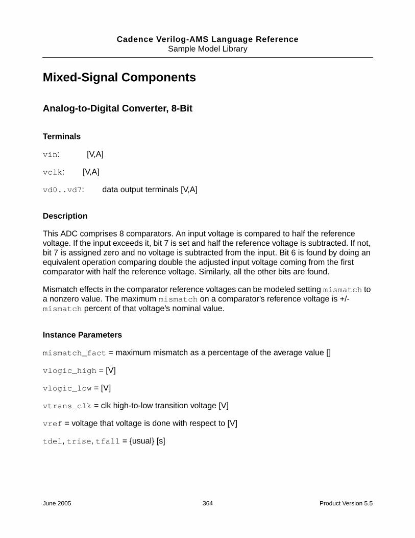
Cadence Verilog-AMS Language ReferenceSample Model Library
Mixed-Signal Components
Analog-to-Digital Converter, 8-Bit
Terminals
vin: [V,A]
vclk: [V,A]
vd0..vd7: data output terminals [V,A]
Description
This ADC comprises 8 comparators. An input voltage is compared to half the referencevoltage. If the input exceeds it, bit 7 is set and half the reference voltage is subtracted. If not,bit 7 is assigned zero and no voltage is subtracted from the input. Bit 6 is found by doing anequivalent operation comparing double the adjusted input voltage coming from the firstcomparator with half the reference voltage. Similarly, all the other bits are found.
Mismatch effects in the comparator reference voltages can be modeled setting mismatch toa nonzero value. The maximum mismatch on a comparator’s reference voltage is +/-mismatch percent of that voltage’s nominal value.
Instance Parameters
mismatch_fact = maximum mismatch as a percentage of the average value []
vlogic_high = [V]
vlogic_low = [V]
vtrans_clk = clk high-to-low transition voltage [V]
vref = voltage that voltage is done with respect to [V]
tdel, trise, tfall = {usual} [s]
June 2005 364 Product Version 5.5

Cadence Verilog-AMS Language ReferenceSample Model Library
Analog-to-Digital Converter, 8-Bit (Ideal)
Terminals
vin: [V,A]
vclk: [V,A]
vd0..vd7: data output terminals [V,A]
Description
This model is ideal because no mismatch is modeled.
Instance Parameters
tdel, trise, tfall = {usual} [s]
vlogic_high = [V]
vlogic_low = [V]
vtrans_clk = clk high-to-low transition voltage [V]
vref = voltage that voltage is done with respect to [V]
June 2005 365 Product Version 5.5

Cadence Verilog-AMS Language ReferenceSample Model Library
Decimator
Terminals
vin: [V,A]
vout: [V,A]
vclk: [V,A]
Description
Produces a cumulative average of N samples of vin. vin is sampled on the positive vclktransition. The cumulative average of the previous set of N samples is output until a new setof N samples has been captured.
Transfer Function: 1/N * (1 - Z^-N)/(1-Z^-1)
Instance Parameters
N = oversampling ratio [V]
vtrans_clk = transition voltage of the clock [V]
tdel, trise, tfall = {usual} [s]
June 2005 366 Product Version 5.5

Cadence Verilog-AMS Language ReferenceSample Model Library
Digital-to-Analog Converter, 8-Bit
Terminals
vd0..vd7: data inputs [V,A]
vout: [V,A]
Description
Mismatch effects can be modeled in this DAC by setting mismatch to a nonzero value. Themaximum mismatch on a bit is +/-mismatch percent of that bit’s nominal value.
Instance Parameters
vref = reference voltage for the conversion [V]
mismatch_fact = maximum mismatch as a percentage of the average value []
vtrans = logic high-to-low transition voltage [V]
tdel, trise, tfall = {usual} [s]
June 2005 367 Product Version 5.5

Cadence Verilog-AMS Language ReferenceSample Model Library
Digital-to-Analog Converter, 8-Bit (Ideal)
Terminals
vd0..vd7: data inputs [V,A]
vout: [V,A]
Instance Parameters
vref = reference voltage that conversion is with respect to [V]
vtrans = transition voltage between logic high and low [V]
tdel, trise, tfall = {usual} [s]
June 2005 368 Product Version 5.5

Cadence Verilog-AMS Language ReferenceSample Model Library
Sigma-Delta Converter (first-order)
Terminals
vin: [V,A]
vclk: [V,A]
vout: [V,A]
Description
This is a model of a first-order sigma-delta analog-to-digital converter.
Instance Parameters
vth = threshold voltage of two-level quantizer [V]
vout_high = range of sigma-delta is 0-vout_high [V]
vtrans_clk = transition of voltage of clock [V]
tdel, trise, tfall = {usual}
June 2005 369 Product Version 5.5

Cadence Verilog-AMS Language ReferenceSample Model Library
Sample-and-Hold Amplifier (Ideal)
Terminals
vin: [V,A]
vclk: [V,A]
vout: [V,A]
Instance Parameters
vtrans_clk = transition voltage of the clock [V]
June 2005 370 Product Version 5.5

Cadence Verilog-AMS Language ReferenceSample Model Library
Single Shot
Terminals
vin: input terminal [V,A]
vout: output terminal [V,A]
Description
This model outputs a logic high pulse of duration pulse_width if a positive transition isdetected on the input.
Instance Parameters
pulse_width = pulse width [s]
vlogic_high = output voltage for high [V]
vlogic_low = output voltage for low [V]
vtrans = voltages above this at input are considered high [V]
tdel, trise, tfall = {usual} [s]
June 2005 371 Product Version 5.5
Cadence Verilog-AMS Language ReferenceSample Model Library
Switched Capacitor Integrator
Terminals
vout_p, vout_n: output terminals [V,A]
vin_p, vin_n: input terminals [V,A]
vphi: switching signal [V,A]
Instance Parameters
cap_in = input capacitor value
cap_fb = feedback capacitor value
vphi_trans = transition voltage of vphi
June 2005 372 Product Version 5.5

Cadence Verilog-AMS Language ReferenceSample Model Library
Power Electronics Components
Full Wave Rectifier, Two Phase
Terminals
vin_top: input [V,A]
tfire: delay after positive zero crossing of each phase before phaserectifier fires [s,A]
vout: rectified output voltage [V,A]
Instance Parameters
ihold = holding current (minimum current for rectifier to work) [A]
switch_time = maximum amount of time to spend attempting switch-on [s]
vdrop_rect = total rectification voltage drop [V]
June 2005 373 Product Version 5.5

Cadence Verilog-AMS Language ReferenceSample Model Library
Half Wave Rectifier, Two Phase
Terminals
vin_top: input [V,A]
tfire: delay after positive zero crossing of each phase before phaserectifier fires [s,A]
vout: rectified output voltage [V,A]
Instance Parameters
ihold = holding current (minimum current for rectifier to work) [A]
switch_time = maximum amount of time to spend attempting switch-on [s]
vdrop_rect = total rectification voltage drop [V]
June 2005 374 Product Version 5.5

Cadence Verilog-AMS Language ReferenceSample Model Library
Thyristor
Terminals
vanode: anode [V,A]
vcathode: cathode [V,A]
vgate: gate [V,A]
Instance Parameters
iturn_on = thyristor gate triggering current [A]
ihold = thyristor hold current [A]
von = thyristor on voltage [V]
June 2005 375 Product Version 5.5

Cadence Verilog-AMS Language ReferenceSample Model Library
Semiconductor Components
Diode
Terminals
vanode: anode voltage [V,A]
vcathode: cathode voltage [V,A]
Description
This model is of a diode based on the Schockley equation.
Instance Parameters
is = saturation current with negative bias [A]
June 2005 376 Product Version 5.5

Cadence Verilog-AMS Language ReferenceSample Model Library
MOS Transistor (Level 1)
Terminals
vdrain: drain [V,A]
vgate: gate [V,A]
vsource: source [V,A]
vbody: body [V,A]
Description
This model is of a basic, level-1, Schichmann-Hodges style model of a MOSFET transistor.
Instance Parameters
width = [m]
length = [m]
vto = threshold voltage [V]
gamma = bulk threshold []
phi = bulk junction potential [V]
lambda = channel length modulation []
tox = oxide thickness []
u0 = transconductance factor []
xj = metallurgical junction depth []
is = saturation current []
cj = bulk junction capacitance [F]
vj = bulk junction voltage [V]
mj = bulk grading coefficient []
June 2005 377 Product Version 5.5

Cadence Verilog-AMS Language ReferenceSample Model Library
fc = forward bias capacitance factor []
tau = parasitic diode factor []
cgbo = gate-bulk overlap capacitance [F]
cgso = gate-source overlap capacitance [F]
cgdo = gate-drain overlap capacitance [F]
dev_type = the type of MOSFET used []
June 2005 378 Product Version 5.5

Cadence Verilog-AMS Language ReferenceSample Model Library
MOS Thin-Film Transistor
Terminals
vdrain: drain terminal [V,A]
vgate_front: front gate terminal [V,A]
vsource: source terminal [V,A]
vgate_back: back gate terminal [V,A]
Description
This model is of a silicon-on-insulator thin-film transistor.
This is a model of a fully depleted back surface thin-film transistor MOSFET model. No short-channel effects.
Instance Parameters
length = length []
width = width []
toxf = oxide thickness [m]
toxb = oxide thickness [m]
nsub = [cm-3]
ngate = [cm-3]
nbody = [cm-3]
tb = [m]
u0 = []
lambda = channel length modulation factor []
dev_type = dev_type []
June 2005 379 Product Version 5.5

Cadence Verilog-AMS Language ReferenceSample Model Library
N JFET Transistor
Terminals
vdrain: drain voltage [V,A]
vgate: gate voltage [V,A]
vsource: source voltage [V,A]
Description
This is a model of an n-channel, junction field-effect transistor.
Instance Parameters
area = area []
vto = threshold voltage [V]
beta = gain []
lambda = output conductance factor []
is = saturation current []
gmin = minimal conductance []
cjs = gate-source junction capacitance [F]
cgd = gate-drain junction capacitance [F]
m = emission coefficient []
phi = gate junction barrier potential []
fc = forward bias capacitance factor []
June 2005 380 Product Version 5.5

Cadence Verilog-AMS Language ReferenceSample Model Library
NPN Bipolar Junction Transistor
Terminals
vcoll: collector [V,A]
vbase: base [V,A]
vemit: emitter [V,A]
vsubs: substrate [V,A]
Description
This is a gummel-poon style npn bjt model.
Instance Parameters
area = cross-section area
is = saturation current []
ise = base-emitter leakage current []
isc = base-collector leakage current []
bf = beta forward []
br = beta reverse []
nf = forward emission coefficient []
nr = reverse emission coefficient []
ne = b-e leakage emission coefficient []
nc = b-c leakage emission coefficient []
vaf = forward Early voltage [V]
var = reverse Early voltage [V]
ikf = forward knee current [A]
June 2005 381 Product Version 5.5

Cadence Verilog-AMS Language ReferenceSample Model Library
ikr = reverse knee current [A]
cje = capacitance, base-emitter junction [F]
vje = voltage, base-emitter junction [V]
mje = b-e grading exponential factor []
cjc = capacitance, base-collector junction [F]
vjc = voltage, base-collector junction [V]
mjc = b-c grading exponential factor []
cjs = capacitance, collector-substrate junction [F]
vjs = voltage, collector-substrate junction [V]
mjs = c-s grading exponential factor []
fc = forward bias capacitance factor []
tf = ideal forward transit time [s]
xtf = tf bias coefficient []
vtf = tf-vbc dependence voltage [V]
itf = high current factor []
tr = reverse diffusion capacitance [s]
June 2005 382 Product Version 5.5

Cadence Verilog-AMS Language ReferenceSample Model Library
Schottky Diode
Terminals
vanode: anode voltage [V,A]
vcathode: cathode voltage [V,A]
Description
This model is of a diode based on the Schockley equation.
Instance Parameters
area = area of junction []
is = saturation current []
n = emission coefficient []
cjo = zero-bias junction capacitance [F]
m = grading coefficient []
phi = body potential [V]
fc = forward bias capacitance [F]
tt = transit time [s]
bv = reverse breakdown voltage [V]
rs = series resistance [Ohms]
gmin = minimal conductance [Mhos]
June 2005 383 Product Version 5.5
Cadence Verilog-AMS Language ReferenceSample Model Library
Telecommunications Components
AM Demodulator
Terminals
vin: AM RF input signal [V,A]
vout: demodulated signal [V,A]
Description
Demodulates the signal in vin and outputs it as vout.
Consists of four stages in series:
1. RF amp amplifier
2. Detector stage (full wave rectifier)
3. AF filters stage is a low-pass filter that extracts the AF signal—has gain of one, and twopoles at af_wn [rad/s]
4. AF amp stage amplifies by af_gain and adds af_lev_shift
Instance Parameters
rf_gain = gain of RF (radio frequency) stage []
af_wn = location of both AF (audio frequency) filter poles [rad/s]
af_gain = gain of the audio amplifier []
af_lev_shift = added to AF signal after amplification and filtering [V]
June 2005 384 Product Version 5.5

Cadence Verilog-AMS Language ReferenceSample Model Library
AM Modulator
Terminals
vin: input signal [V,A]
vout: modulated signal [V,A]
Description
vin is limited to the range between vin_max and vin_min. It is also scaled so that it lieswithin the +/-1 range. This produces vin_adjusted. vout is given by the following formula:
vout = unmod_amp * (1 + mod_depth * vin_adjusted) * cos (2 * PI * f_carrier * time)
Instance Parameters
f_carrier = carrier frequency [Hz]
vin_max = maximum input signal [V]
vin_min = minimum input signal [V]
mod_depth = modulation depth []
unmod_amp = unmodulation carrier amplitude [V]
June 2005 385 Product Version 5.5

Cadence Verilog-AMS Language ReferenceSample Model Library
Attenuator
Terminals
vin: AM input signal [V,A]
vout: rectified AM signal [V,A]
Description
vout is attenuated by attenuation.
Instance Parameters
attenuation = 20log10 attenuation [dB]
June 2005 386 Product Version 5.5

Cadence Verilog-AMS Language ReferenceSample Model Library
Audio Source
Terminals
vin: [V,A]
vout: [V,A]
Description
This model synthesizes an audio source. Its output is the sum of 4 sinusoidal sources.
Instance Parameters
amp1 = amplitude of the first sinusoid [V]
amp2 = amplitude of the second sinusoid [V]
amp3 = amplitude of the third sinusoid [V]
amp4 = amplitude of the fourth sinusoid [V]
freq1 = frequency of the first sinusoid [Hz]
freq2 = frequency of the second sinusoid [Hz]
freq3 = frequency of the third sinusoid [Hz]
freq4 = frequency of the fourth sinusoid [Hz]
June 2005 387 Product Version 5.5

Cadence Verilog-AMS Language ReferenceSample Model Library
Bit Error Rate Calculator
Terminals
vin1: [V,A]
vin2: [V,A]
Description
This model compares the two input signals tstart+tperiod/2 and every tperiodseconds later. At the end of the simulation, it prints the bit error rate, which is the number oferrors found divided by the number of bits compared.
Instance Parameters
tstart = when to start measuring [s]
tperiod = how often to compare bits [s]
vtrans = voltages above this at input are considered high [V]
June 2005 388 Product Version 5.5

Cadence Verilog-AMS Language ReferenceSample Model Library
Charge Pump
Terminals
vout: output terminal from which charge pumped/sucked [V,A]
vsrc: source terminal from which charge sourced/sunk [V,A]
siginc, sigdec: Logic signal that controls charge pump operation [V,A]
Description
This model can source of sink a fixed current, iamp. Its mode depends on the values ofsiginc and sigdec;
When siginc > vtrans, iamp amps are pumped from the output. When sigdec >vtrans, iamp amps are sucked into the output. When both siginc and sigdec are in thesame state, no current is sucked/pumped.
Instance Parameters
iamp = charging current magnitude [A]
vtrans = voltages above this at input are considered high [V]
tdel, trise, tfall = {usual} [s]
June 2005 389 Product Version 5.5

Cadence Verilog-AMS Language ReferenceSample Model Library
Code Generator, 2-Bit
Terminals
vout0, vout1: output bits [V,A]
Description
Generates a pair of random binary signals.
Instance Parameters
seed = random seed
tperiod = period of output code [s]
vlogic_high = output voltage for high [V]
vlogic_low = output voltage for low [V]
tdel, trise, tfall = {usual} [s]
June 2005 390 Product Version 5.5
Cadence Verilog-AMS Language ReferenceSample Model Library
Code Generator, 4-Bit
Terminals
vout_b0-3: output bits [V,A]
Description
This model is of a random 4-bit code generator.
This model outputs a different, randomly generated, 4-bit code every tperiod seconds.
Instance Parameters
tperiod = period of the code generation [s]
vlogic_high = output voltage for high [V]
vlogic_low = output voltage for low [V]
tdel, trise, tfall = {usual} [s]
June 2005 391 Product Version 5.5

Cadence Verilog-AMS Language ReferenceSample Model Library
Decider
Terminals
vin: [V,A]
vout: [V,A]
Description
This model samples this input signal a number of times and outputs the most likely value ofthe binary data contained in the signal.
A decision on what data is contained in the input is made each tperiod. During eachdecision period, a sample of the input is taken each tsample. A count of the number ofsamples with values greater than (vlogic_high + vlogic_low)/2 is kept. If at the end ofthe period, this count is greater than half the number of samples taken, a logic 1 is output. Ifit is less than half the number of samples, vlogic_low is output. Otherwise, the output is(vlogic_high + vlogic_low)/2.
The sampling starts at tstart.
Instance Parameters
tperiod = period of binary data being extracted [s]
tsample = sampling period [s]
vlogic_high = output voltage for high [V]
vlogic_low = output voltage for low [V]
tstart = time at which to start sampling [s]
tdel, trise, tfall = {usual} [s]
June 2005 392 Product Version 5.5

Cadence Verilog-AMS Language ReferenceSample Model Library
Digital Phase Locked Loop (PLL)
Terminals
vin: [V,A]
vout: [V,A]
Description
The model comprises a number of submodels: digital phase detector, a change pump, a low-pass filter (LPF), and a digital voltage-controlled oscillator (VCO).
They are arranged in the following way:
___________ ________ _______| | | | Iq Vin_VCO | |
Vin------| Phase |------| Charge |--->--|----------| || | | | V | VCO |
----| Detector |------| Pump | ___|___ | || |___________| |________| | | |_______|| | | RC | || | |Network| || | | (LPF) | |---Vout| V_local_osc | |_______| || | | || |----------- || | || __|__ || gnd ///// || ||-----------------------------------------------------|
Instance Parameters
pump_iamp = amplitude of the charge pump’s output current [A]
vco_cen_freq = center frequency of the VCO [Hz]
vco_gain = the gain of the VCO []
lpf_zero_freq = zero frequency of LPF (low-pass filter) [Hz]
lpf_pole_freq = pole frequency of LPF [Hz]
lpf_r_nom = nominal resistance of RC network implementing LPF
June 2005 393 Product Version 5.5

Cadence Verilog-AMS Language ReferenceSample Model Library
Digital Voltage-Controlled Oscillator
Terminals
vin: [V,A]
vout: [V,A]
Description
The output is a square wave with instantaneous frequency:
center_freq + vco_gain * vin
Instance Parameters
center_freq = center frequency of oscillation frequency when vin = 0 [Hz]
vco_gain = oscillator conversion gain [Hz/volt]
vlogic_high = output voltage for high [V]
vlogic_low = output voltage for low [V]
tdel, trise, tfall = {usual} [s]
June 2005 394 Product Version 5.5

Cadence Verilog-AMS Language ReferenceSample Model Library
FM Demodulator
Terminals
vin: FM RF input signal [V,A]
vout: demodulated signal [V,A]
Description
Demodulates the signal in vin and outputs it as vout.
Consists of four stages in series:
1. RF amp stage amplifiers vin
2. Detector stage is a phase locked loop (PLL)
3. AF filters stage is a low-pass filter that extracts the AF signal. The filter has gain of one,and two poles at af_wn [rad/s]
4. AF amp stage amplifies by af_gain and adds af_lev_shift.
Instance Parameters
rf_gain = gain of RF (radio frequency) stage []
pll_out_bw = bandwidth of PLL output filter [Hz]
pll_vco_gain = gain of the PLL’s VCO []
pll_vco_cf = the center frequency of the PLLs [Hz]
af_wn = location of both AF (audio frequency) filter poles [Hz]
af_gain = gain of the audio amplifier []
af_lev_shift = added to AF signal after amplification and filtering [V]
June 2005 395 Product Version 5.5

Cadence Verilog-AMS Language ReferenceSample Model Library
FM Modulator
Terminals
vin: input signal [V,A]
vout: modulated signal [V,A]
Description
vout = amp * sin (phase)
where phase = integ (2 * PI * f_carrier + vin_gain * vin)
Instance Parameters
f_carrier = carrier frequency [Hz]
amp = amplitude of the FM modulator output []
vin_gain = amplification of vin_signal before it is used to modulate the FM carrier signal []
June 2005 396 Product Version 5.5

Cadence Verilog-AMS Language ReferenceSample Model Library
Frequency-Phase Detector
Terminals
vin_if: signal whose phase is being detected [V,A]
vin_lo: signal from local oscillator [V,A]
sigout_inc: logic signal to control charge pump [V,A]
sigout_dec: logic signal to control charge pump [V,A]
Description
The freq_ph_detector can have three states: behind, ahead, and same. The specificstate is determined by the positive-going transitions of the signals vin_if and vin_lo.
Positive transitions on vin_if causes the state to become the next higher state unless thestate is already ahead.
Positive transitions on vin_lo cause the state to become the next lower state unless thestate is already behind.
The output depends on the state the detector is in:
ahead => sigout_inc = high, sigout_dec = low
same => sigout_inc = high, sigout_dec = high
behind => sigout_inc = low, sigout_dec = high
The output signals are expected to be used by a charge_pump.
Instance Parameters
vlogic_high = output voltage for high [V]
vlogic_low = output voltage for low [V]
vtrans = voltages above this at input are considered high [V]
tdel, trise, tfall = {usual} [s]
June 2005 397 Product Version 5.5

Cadence Verilog-AMS Language ReferenceSample Model Library
Mixer
Terminals
vin1, vin2: [V,A]
vout: [V,A]
Description
vout = gain * vin1 * vin2
Instance Parameters
gain = gain of mixer []
June 2005 398 Product Version 5.5

Cadence Verilog-AMS Language ReferenceSample Model Library
Noise Source
Terminals
vin: [V,A]
vout: [V,A]
Description
This is an approximate white noise source.
Note: It is not a true white source because its output changes every time step and the timestep is dependent on the behavior of the circuit.
Instance Parameters
amp = amplitude of the output signal about 0 [V]
June 2005 399 Product Version 5.5

Cadence Verilog-AMS Language ReferenceSample Model Library
PCM Demodulator, 8-Bit
Terminals
vin: input signal [V,A]
vout: demodulated signal [V,A]
Description
The PCM demodulator samples vin at bit_rate [Hz] starting at tstart + 0.5/bit_rate.Each set of 8 samples is considered a binary word, and these sets are converted to an outputvoltage using a linear 8-bit binary code with 0 representing vin_min and 255 representingvin_max. The first bit received is the LSB, bit 0; the last bit received is the MSB, bit 7.
The output rate is bit_rate/8.
Instance Parameters
freq_sample = sample frequency [Hz]
tstart = when to start sampling [s]
vout_min = minimum input voltage [V]
vout_max = maximum input voltage [V]
vtrans = voltages above this at input are considered high [V]
tdel, trise, tfall = {usual} [s]
June 2005 400 Product Version 5.5
Cadence Verilog-AMS Language ReferenceSample Model Library
PCM Modulator, 8-Bit
Terminals
vin: input signal [V,A]
vout: modulated signal [V,A]
Description
The PCM modulator samples vin at a sample_freq [Hz] starting at tstart. Once asample has been obtained, it is converted to a linear 8-bit binary code with 0 representingvin_min and 255 representing vin_max.
The bits are in the code and are sequentially put through vout at a rate 8 timessample_freq with vlogic_high signifying a 1 and vlogic_low signifying a 0. The firstbit transmitted is the LSB, bit 0; the last bit transmitted is the MSB, bit 7.
Clipping occurs when the input is outside vin_min and vin_max.
Instance Parameters
sample_freq = sample frequency [Hz]
tstart = when to start sampling [s]
vin_min = minimum input voltage [V]
vin_max = maximum input voltage [V]
vlogic_high = output voltage for high [V]
vlogic_low = output voltage for low [V]
tdel, trise, tfall = {usual} [s]
June 2005 401 Product Version 5.5

Cadence Verilog-AMS Language ReferenceSample Model Library
Phase Detector
Terminals
vlocal_osc: local oscillator voltage [V,A]
vin_rf: PLL radio frequency input voltage [V,A]
vif: intermediate frequency output voltage [V,A]
Instance Parameters
gain = gain of detector []
mtype = type of phase detection to be used; chopper or multiplier []
June 2005 402 Product Version 5.5

Cadence Verilog-AMS Language ReferenceSample Model Library
Phase Locked Loop
Terminals
vlocal_osc: local oscillator voltage [V,A]
vin_rf: PLL radio frequency input voltage [V,A]
vout: voltage proportional to the frequency being locked onto [V,A]
vout_ph_det: output of the phase detector [V,A]
Instance Parameters
vco_gain = gain of VCO cell [Hz/V]
vco_center_freq = VCO oscillation frequency [Hz]
phase_detect_type = type of phase detection cell to be used []
vout_filt_bandwidth = bandwidth of the low-pass filter on output [Hz]
June 2005 403 Product Version 5.5

Cadence Verilog-AMS Language ReferenceSample Model Library
PM Demodulator
Terminals
vin: PM RF input signal [V,A]
vout: demodulated signal [V,A]
Description
Demodulates the signal in vin and outputs it as vout.
Consists of four stages in series:
1. RF amp stage amplifiers vin.
2. Detector stage is a phase locked loop (PLL)—the phase detector output is tapped.
3. AF filters stage is a low-pass filter that extracts the AF signal—has gain of one, and twopoles at af_wn [rad/s].
4. AF amp stage amplifies by af_gain and adds af_lev_shift.
Instance Parameters
rf_gain = gain of RF (radio frequency) stage []
pll_out_bw = bandwidth of PLL output filter [Hz]
pll_vco_gain = gain of the PLL’s VCO []
pll_vco_cf = the center frequency of the PLLs [Hz]
af_wn = location of both AF (audio frequency) filter poles [Hz]
af_gain = gain of the audio amplifier []
af_lev_shift = added to AF signal after amplification and filtering [V]
June 2005 404 Product Version 5.5

Cadence Verilog-AMS Language ReferenceSample Model Library
PM Modulator
Terminals
vin: input signal [V,A]
vout: modulated signal [V,A]
Description
vout = amp * sin(2 * PI * f_carrier * time + phase_max * vin_adjusted)
where vin_adjusted is scaled version of vin that lies within the +/-1 range.
Before scaling, vin is limited to the range between vin_max and vin_min by clipping.
Instance Parameters
f_carrier = carrier frequency [Hz]
amp = amplitude of the PM modulator output []
vin_max = maximum acceptable input (clipping occurs above this) [V]
vin_min = minimum acceptable input (clipping occurs above this) [V]
phase_max = the phase shift produced when the modulating signal is at vin_max [rad]
June 2005 405 Product Version 5.5

Cadence Verilog-AMS Language ReferenceSample Model Library
QAM 16-ary Demodulator
Terminals
vin: input [V,A]
vout_bit[0-4]: demodulated codes [V,A]
Description
This model is of a QPSK (quadrature phase shift key) modulator.
Demodulates a 16ary encoded QAM signal by separately sampling the input signal at 90degrees (q-phase) and 180 degrees (i-phase).
This model does not contain a dynamic synchronizing mechanism for ensuring that samplingoccurs at the correct time points. Synchronizing can be statically adjusted by changingtstart. tstart should correspond to when the input QAM signal is at 0 degrees.
The i-phase contains the two MSBs. The q-phase contains the two LSBs.
The constellation diagram representing this relationship follows.
^/ \| Q phase
_____________|______________| | | | || 0011 | 0111 | 1011 | 1111 |
0 |______|______|______|______|| | | | |
V | 0010 | 0110 | 1010 | 1110 |o ___|______|______|______|______|___________\ I Phasel | | | | | /t | 0001 | 0101 | 1001 | 1101 |s |______|______|______|______|
| | | | || 0000 | 0100 | 1000 | 1100 ||______|______|______|______|
||
0 Volts
Each code box is vbox_width volts wide.
Instance Parameters
freq = demodulation frequency [Hz]
June 2005 406 Product Version 5.5

Cadence Verilog-AMS Language ReferenceSample Model Library
vbox_width = width of modulation code box in constellation diagram [V]
vlogic_high = output voltage for high [V]
vlogic_low = output voltage for low [V]
tdel, trise, tfall = {usual} [s]
June 2005 407 Product Version 5.5

Cadence Verilog-AMS Language ReferenceSample Model Library
Quadrature Amplitude 16-ary Modulator
Terminals
vin_b[0-3]: bits of input code [V,A]
vout: modulated output [V,A]
Description
This model does 16 value (4-Bit) QAM.
It encodes the MSBs on the i-phase and the LSBs on the q-phase. Its constellation diagramcan be represented as
/ \| Q phase
_____________|______________| | | | || 0011 | 0111 | 1011 | 1111 |
0 |______|______|______|______|| | | | |
V | 0010 | 0110 | 1010 | 1110 |o ___|______|______|______|______|___________\ I Phasel | | | | | /t | 0001 | 0101 | 1001 | 1101 |s |______|______|______|______|
| | | | || 0000 | 0100 | 1000 | 1100 ||______|______|______|______|
|0 Volts
The two MSBs are encoded on the i-phase. The two LSBs are encoded on the q-phase.
The modulating formula is Vout = i_phase * cos(wt) + q_phase * sin(wt)
i_phase and q_phase vary between -phase_ampl and phase_ampl.
Instance Parameters
freq = modulation frequency [Hz]
phase_ampl = amplitude of the i-phase and q-phase signals [V]
vtrans = voltages above this at input are considered high [V]
tdel, trise, tfall = {usual} [s]
June 2005 408 Product Version 5.5

Cadence Verilog-AMS Language ReferenceSample Model Library
QPSK Demodulator
Terminals
vin: input [V,A]
vout_i: i-phase output [V,A]
vout_q: q-phase output [V,A]
Description
Does a QPSK demodulation on the input signal. It does not contain a dynamic synchronizingmechanism. Synchronizing can be adjusted by changing tstart.
Detection works by separately sampling the i-phase of vin and the q-phase of vin at freqHz and 90 degrees out of phase. The first i-phase sample is done at tstart + 0.5/freq, thenext 1/freq seconds later, etc. Similarly, the first q-phase sample is done at tstart + 0.25/freq, the next 1/freq seconds later, and so on.
For the i-phase, a high is detected if the sample < -vthresh. For the q-phase, a high isdetected if the sample > vthresh.
Instance Parameters
freq = demodulation frequency [Hz]
vthresh = threshold detection voltage [V]
vlogic_high = output voltage for high [V]
vlogic_low = output voltage for low [V]
tstart = time at which demodulation starts [s]
tdel, trise, tfall = {usual} [s]
June 2005 409 Product Version 5.5

Cadence Verilog-AMS Language ReferenceSample Model Library
QPSK Modulator
Terminals
vin_i, vin_q: quadrature inputs [V,A]
vout: modulator output [V,A]
Description
This takes two sampled quadrature inputs and does QPSK modulation on them.
Instance Parameters
freq = modulation frequency [Hz]
amp = modulator amplitude [V]
vtrans = voltages above this at input are considered high [V]
tdel, trise, tfall = {usual} [s]
June 2005 410 Product Version 5.5
Cadence Verilog-AMS Language ReferenceSample Model Library
Random Bit Stream Generator
Terminal
vout: [V,A]
Description
This model generates a random stream of bits.
Instance Parameters
tperiod = period of stream [s]
seed = random number seed []
vlogic_high = output voltage for high [V]
vlogic_low = output voltage for low [V]
tdel, trise, tfall = {usual} [s]
June 2005 411 Product Version 5.5

Cadence Verilog-AMS Language ReferenceSample Model Library
Transmission Channel
Terminals
vin: AM input signal [V,A]
vout: rectified AM signal [V,A]
Description
vin has noise_amp noise added to it and the resultant is attenuated by attenuation [dB].
Instance Parameters
attenuation = 20log10 attenuation [dB]
noise_amp = amplitude of noise added to vin before attenuation [V]
June 2005 412 Product Version 5.5
Cadence Verilog-AMS Language ReferenceSample Model Library
Voltage-Controlled Oscillator
Terminals
vin: oscillation-controlling voltage [V,A]
vout: [V,A]
Instance Parameters
amp = amplitude of the output signal [V]
center_freq = center frequency of oscillation frequency when vin = 0 [Hz]
vco_gain = oscillator conversion gain [Hz/volt]
June 2005 413 Product Version 5.5

Cadence Verilog-AMS Language ReferenceSample Model Library
June 2005 414 Product Version 5.5

Cadence Verilog-AMS Language Reference
EVerilog-A Keywords
This appendix contains the list of the Cadence® Verilog®-A language keywords. Keywordsare predefined nonescaped identifiers that are used to define the language constructs. Somekeywords are not used in this release.
The simulator does not interpret a Verilog-A keyword preceded by a backslash character asa keyword. For more information, see “Identifiers” on page 44.
above
abs
absdelay
acos
acosh
ac_stim
aliasparam
always
analog
analysis
and
asin
asinh
assign
atan
atan2
atanh
begin
bound_step
branch
buf
bufif0
bufif1
case
casex
casez
ceil
cmos
connectrules
cos
cosh
cross
ddt
deassign
default
defparam
delay
disable
discipline
discontinuity
driver_update
edge
else
end
endcase
June 2005 415 Product Version 5.5

Cadence Verilog-AMS Language ReferenceVerilog-A Keywords
endconnectrules
enddiscipline
endfunction
endmodule
endnature
endprimitive
endspecify
endtable
endtask
event
exclude
exp
final_step
flicker_noise
floor
flow
for
force
forever
fork
from
function
generate
genvar
ground
highz0
highz1
hypot
idt
idtmod
if
ifnone
inf
initial
initial_step
inout
input
integer
join
laplace_nd
laplace_np
laplace_zd
laplace_zp
large
last_crossing
limexp
ln
log
macromodule
max
medium
min
module
nand
nature
negedge
net_resolution
nmos
noise_table
nor
not
notif0
notif1
or
output
parameter
pmos
posedge
potential
pow
primitive
pull0
June 2005 416 Product Version 5.5

Cadence Verilog-AMS Language ReferenceVerilog-A Keywords
pull1
pullup
pulldown
pwr
rcmos
real
realtime
reg
release
repeat
rnmos
rpmos
rtran
rtranif0
rtranif1
scalared
sin
sinh
slew
small
specify
specparam
sqrt
strobe
strong0
strong1
supply0
supply1
table
table_model
tan
tanh
task
temperature
time
timer
tran
tranif0
tranif1
transition
tri
tri0
tri1
triand
trior
trireg
vectored
vt
wait
wand
weak0
weak1
while
white_noise
wire
wor
wreal
xnor
xor
zi_nd
zi_np
zi_zd
zi_zp
June 2005 417 Product Version 5.5

Cadence Verilog-AMS Language ReferenceVerilog-A Keywords
Keywords to Support Backward Compatibility
The keywords in this section are provided for backward compatibility.
abstol
access
bound_step
ddt_nature
delay
discontinuity
idt_nature
temperature
units
vt
Discipline and Nature Keywords
Discipline and nature keywords are used between the keywords discipline andenddiscipline and between the keywords nature and endnature. The items listedbelow are keywords only in that context.
abstol
access
continuous
ddt_nature
discrete
domain
idt_nature
units
Connect Rules Keywords
Connect rules keywords are used between the keywords connectrules andendconnectrules. The items listed below are keywords only in that context.
connect
merged
resolveto
split
June 2005 418 Product Version 5.5

Cadence Verilog-AMS Language Reference
FUnsupported Elements of Verilog-AMS
The Cadence® Verilog®-AMS language is specified in the Verilog-AMS LanguageReference Manual: Analog & Mixed-Signal Extensions to Verilog HDL, produced byOpen Verilog International. The Cadence implementation of Verilog-AMS does not supportall of the specified elements of the Verilog-AMS language in all the contexts in which thelanguage specification says they are to be supported.
The tables in this section list the unsupported elements according to the followingclassifications:
■ Unsupported elements that should be supported in behavioral contexts, such as:expressions; initial, always, and analog blocks; and user-defined tasks and functions.
■ Unsupported elements that should be supported in analog contexts, such as analogblocks and analog functions.
■ Unsupported elements that should be supported in structural contexts such as those thatexist outside behavioral contexts and have to do with hierarchy, natures, and disciplines.
■ Unsupported elements that should be supported in digital contexts, such as initial andalways blocks, and user-defined digital tasks and digital functions.
June 2005 419 Product Version 5.5

Cadence Verilog-AMS Language ReferenceUnsupported Elements of Verilog-AMS
Unsupported Elements for Behavioral Contexts
Feature Comment
Net attributes, except fornet.potential.abstol andnet.flow.abstol, which are supported
String variables Cannot be assigned in analog block. Cannotbe used in $strobe in the analog block.
Using probes containing vector net elementsin a digital block.
Out-of-module references Not supported to analog nets, branches, ornature attributes.
Standard math and transcendental functions Inside the analog block, expressions thatcontain hierarchical references are notsupported. Domain ranges are checked onlyfor exp, sqrt, pow, and atan2.
$rdist functions Supported in analog contexts but not indigital contexts.
Global events The @analog_identifier form is notsupported.
@timer Not supported in the digital context.
$realtime Not supported in the analog context. Use$abstime instead, in the analog context.
Unsupported Elements for Behavioral Analog Contexts
Feature Comment
Parameters used to specify ranges for thegenerate statement
Parameter declarations Not supported in analog user-definedfunctions.
The genvar statement
Arrays passed to functions
June 2005 420 Product Version 5.5

Cadence Verilog-AMS Language ReferenceUnsupported Elements of Verilog-AMS
ddt (time derivative) operator Nesting is not allowed. For example,ddt(ddt()) is prohibited. The abstolargument has no effect. A nature cannot beused as an argument.
Laplace transform filters Parameter-sized array arguments are notsupported.
Analog functions Parameters are not allowed as arguments.
Analog vector nets Not supported for the Tcl value command.
Digital transition sensitivities Transition sensitivities such as @dVal arenot supported in analog contexts. Eventsensitivities such as
@(posedge dVal or negedge dVal)
must be used instead.
The concatenation operator
$stime
$time
$monitor and $fmonitor
$monitor off/on
$printtimescale
$timeformat
$bitstoreal
$itor
$realtobits
$rtoi
$readmen used with the %b, %h, and %rspecifications.
Unsupported Elements for Behavioral Analog Contexts
Feature Comment
June 2005 421 Product Version 5.5

Cadence Verilog-AMS Language ReferenceUnsupported Elements of Verilog-AMS
Unsupported Elements for Structural Contexts
Feature Comment
Derived natures
Overriding nature attributes from disciplines
Array ranges for nets
Array ranges for ground nodes
Parameter arrays Parameter array declarations are notsupported. Parameter array assignments aresupported only in analog primitives.
Module instantiation inside a generateblock
Generate blocks, because they can beused only in analog blocks, can containonly behavioral code.
Parameter-sized vector nets
User-defined attributes Only the Cadence huge, blowup, andmaxdelta attributes are supported.
Vector branches
Vector arguments for simulator functions
Vector ground nodes
Parameter-sized ports
Out-of-module references Supported for voltage probes on nets. Notsupported for branches, or for natureattributes.
Discipline resolution If out-of-module references are used in portconnections, the port discipline is not used todetermine the discipline of the out-of-modulereference.
net_resolution
June 2005 422 Product Version 5.5

Cadence Verilog-AMS Language ReferenceUnsupported Elements of Verilog-AMS
The next list contains only VPI functions. The unsupported aspect of these functions is thatthey cannot be called with wreal arguments, digital real vectors, or analog arguments of anykind.
Unsupported Elements for Behavioral Digital Contexts When wreal Arguments AreUsed
Feature Comment
$compare
$strobe_compare
$countdrivers
$deposit
$incpattern_read
$async$and$array
$async$nand$array
$async$or$array
$async$nor$array
$sync$and$array
$sync$nand$array
$sync$or$array
$sync$nor$array
$async$and$plane
$async$nand$plane
$async$or$plane
$async$nor$plane
$sync$and$plane
$sync$nand$plane
$sync$or$plane
$sync$nor$plane
$q_initialize
$q_full
June 2005 423 Product Version 5.5

Cadence Verilog-AMS Language ReferenceUnsupported Elements of Verilog-AMS
$q_remove
$q_add
$q_exam
$scope
$dumpports
$dumpports_close
$lsi_dumpports
$lsi_close
$writememb
$writememh
$recordvars
$recordfile
$recordon
$recordoff
$signalscan
$signalscankill
$signalscanabort
$recordabort
$recordclose
$recordfilecopy
$recordfilechange
$signalscanconnect
$signalscancommand
$recordsetup
Unsupported Elements for Behavioral Digital Contexts When wreal Arguments AreUsed, continued
Feature Comment
June 2005 424 Product Version 5.5

Cadence Verilog-AMS Language Reference
GUpdating Verilog-A Modules
The Verilog®-A language is a subset of Verilog-AMS, but some of the language elements inthat subset have changed since Verilog-A was released by itself. As a consequence, youmight need to revise your Verilog-A modules before using them as Verilog-AMS modules. Thefollowing table highlights the differences.
Feature IndependentVerilog-A Verilog-AMS Change
type
Analog time $realtime $abstime new
Empty discipline Predefined as type wire Type not defined defaultdefinition
Implicit nodes ’default_nodetypediscipline_identifierdefault: wire
default type: emptydiscipline, no domain type
defaultdefinition
initial_step Default = TRAN Default = ALL defaultdefinition
final_step Default = TRAN Default = ALL defaultdefinition
$realtime $realtime:timescale =1 sec
$realtime:timescale= ’timescaledef=1n. See $abstime
definition
Discontinuityfunction
discontinuity(x) $discontinuity(x) syntax
Limitingexponentialfunction
$limexp(expression) limexp(expression) syntax
June 2005 425 Product Version 5.5

Cadence Verilog-AMS Language ReferenceUpdating Verilog-A Modules
Suggestions for Updating Models
The remainder of this appendix describes some of these changes in greater detail andsuggests ways of modifying your existing Verilog-A models so that they work in version 4.4.6of Verilog-A and in version 1.0 of Verilog-AMS. The changes recommended here might notwork with 4.4.5 or earlier versions of Verilog-A.
Port branch access I(a,a)
Note: Cadence® Verilog-Asupports only this form.
I(<a>)
Note: This form is notsupported in CadenceVerilog-A.
syntax
Timestep control(maximumstepsize)
bound_step(const_expression)
$bound_step(expr) syntax
Continuouswaveform delay
delay() absdelay() syntax
User-definedanalog functions
Function Analog function syntax
Discipline domain N/A, assumed continuous Now continuous (default)and discrete
Extension
Time tolerance ontimer functions
N/A Supports additional timetolerance argument fortimer()
Extension
Time tolerance ontransition filter
N/A Supports additional timetolerance argument fortransition()
Extension
’default_nodetype ’default_nodetype ’default_discipline Obsolete
Generatestatement
generate N/A Obsolete
Null statement ; Limited to case,conditional, andevent statements
Obsolete
Feature IndependentVerilog-A Verilog-AMS Change
type
June 2005 426 Product Version 5.5

Cadence Verilog-AMS Language ReferenceUpdating Verilog-A Modules
Current Probes
OVI Verilog-A 1.0 syntax for a current probe is I(a,a). OVI Verilog-AMS 2.0 changes this toI(<a>).
Suggested change: Put I(<a>) inside an `ifdef __VAMS_ENABLE__, which makes thesyntax effective only for Verilog-AMS. For example, change
iin_val = I(vin,vin);
to
`ifdef __VAMS_ENABLE__iin_val = I(<vin>);
`elseiin_val = I(vin,vin);
`endif
Verilog-A warning: None
Analog Functions
OVI Verilog-A 1.0 declaration of an analog function is
function name;
OVI Verilog-AMS 2.0 uses the syntax
analog function name;
Suggested change: Prefix all function declarations by the word analog. For example,change
function real foo;
to
analog function real foo;
Verilog-A warning: None
NULL Statements
OVI Verilog-A 1.0 allows NULL statements to be used anywhere in an analog block. OVIVerilog-AMS 2.0 allows NULL statements to be used only after case statements or eventcontrol statements.
Suggested change:
Remove illegal NULL statements. For example, change
June 2005 427 Product Version 5.5

Cadence Verilog-AMS Language ReferenceUpdating Verilog-A Modules
beginend;
to
beginend
Verilog-A warning: None
inf Used as a Number
Spectre Verilog-A allows 'inf to be used as a number. OVI Verilog-AMS 2.0 allows 'inf tobe used only on ranges.
Suggested change:
Change all illegal references to 'inf to a large number such as 1M. For example, change;
parameter real points_per_cycle = inf from [6:inf];
to
parameter real points_per_cycle = 1M from [6:inf];
Verilog-A warning: None
Changing Delay to Absdelay
OVI Verilog-A 1.0 uses delay as the analog delay operator but OVI Verilog-AMS 2.0 usesabsdelay.
Suggested change: Change delay to absdelay. This change usually leads to faster,better results.
Verilog-A warning: None
Changing $realtime to $abstime
OVI Verilog-A 1.0 uses $realtime as absolute time but OVI Verilog-AMS 2.0 uses$abstime.
Suggested change: Change $realtime to $abstime.
Verilog-A warning: Yes
June 2005 428 Product Version 5.5

Cadence Verilog-AMS Language ReferenceUpdating Verilog-A Modules
Changing bound_step to $bound_step
OVI Verilog-A 1.0 uses bound_step for step bounding but OVI Verilog-AMS 2.0 uses$bound_step.
Suggested change: Change bound_step to $bound_step.
Verilog-A warning: None
Changing Array Specifications
OVI Verilog-A 1.0 uses [] to specify arrays but OVI Verilog-AMS 2.0 uses {}.
Suggested change: Change [] to {}. For example, change
svcvs #(.poles([-2*`PI*bw,0])) output_filter
to
svcvs #(.poles({-2*`PI*bw,0})) output_filter
Verilog-A warning: None
Chained Assignments Made Illegal
Spectre-Verilog-A allows chained assignments, such as x=y=z, but OVI Verilog-AMS 2.0makes this illegal.
Suggested change: Break chain assignments into single assignments. For example,change
x=y=z;
to
y = z; x = y;
Verilog-A warning: None
Real Argument Not Supported as Direction Argument
Spectre-Verilog-A allows real numbers to be used for the arguments of @cross andlast_crossing but OVI Verilog-AMS 2.0 makes this illegal.
Suggested change: Change the real numbers to integers. For example, change
@(cross(V(in),1.0) begin
June 2005 429 Product Version 5.5

Cadence Verilog-AMS Language ReferenceUpdating Verilog-A Modules
to
@(cross(V(in),1) begin
Verilog-A warning: None
$limexp Changed to limexp
OVI Verilog-A 1.0 uses $limexp, but OVI Verilog-AMS 2.0 uses limexp.
Suggested change: Change $limexp to limexp. For example, change
I(vp,vn) <+ is * ($limexp(vacross/$vt) - 1);
to
I(vp,vn) <+ is * (limexp(vacross/$vt) - 1);
Verilog-A warning: None
'if 'MACRO is Not Allowed
Spectre-Verilog-A allows users to type 'if 'MACRO, but OVI Verilog-AMS 2.0, 1.0 and 1364say this is illegal.
Suggested change: Change 'if 'MACRO to 'if MACRO (Do not use the tick mark forthe macro). For example, change
`ifdef `CHECK_BACK_SURFACE
to
`ifdef CHECK_BACK_SURFACE
Verilog-A warning: None
$warning is Not Allowed
Spectre-Verilog-A supports $warning, but OVI Verilog-AMS 2.0, 1.0 and 1364 do notsupport this as a standard built-in function.
Suggested change: Change $warning to $strobe.
Verilog-A warning: None
June 2005 430 Product Version 5.5

Cadence Verilog-AMS Language ReferenceUpdating Verilog-A Modules
discontinuity Changed to $discontinuity
OVI Verilog-A 1.0 uses discontinuity, but OVI Verilog-AMS 2.0 uses $discontinuity.
Suggested change: Change discontinuity to $discontinuity.
Verilog-A warning: None
June 2005 431 Product Version 5.5

Cadence Verilog-AMS Language ReferenceUpdating Verilog-A Modules
June 2005 432 Product Version 5.5

Cadence Verilog-AMS Language Reference
Glossary
A
analog contextThe context of statements that appear in the body of an analog block.
analog HDLAn analog hardware description language for describing analog circuits and functions.
analog portA port whose connections are both analog.
analog signalA hierarchical collection of interconnected nets, where all the nets are of a continuousdiscipline.
B
behavioral descriptionThe mathematical mapping of inputs to outputs for a module, including intermediatevariables and control flow.
behavioral modelA version of a module with a unique set of parameters designed to model a specificcomponent.
blockA level within the behavioral description of a module, delimited by begin and end.
branchA path between two nodes. Each branch has two associated quantities, a potential anda flow, with a reference direction for each.
June 2005 433 Product Version 5.5

Cadence Verilog-AMS Language ReferenceGlossary
C
componentThe fundamental unit within a system. A component encapsulates behavior andstructure. Modules and models can represent a single component, or a component withmany subcomponents.
connect moduleA module automatically or manually inserted by using the connect statement, whichcontains the code required to translate and propagate signals between the analog anddigital nets comprising a signal.
constitutive relationshipsThe expressions and statements that relate the outputs, inputs, and parameters of amodule. These relationships constitute a behavioral description.
continuous context
continuous netA net of a continuous discipline.
continuous variableA variable whose value is calculated in the continuous domain.
control flowThe conditional and iterative statements that control the behavior of a module. Thesestatements evaluate variables (counters, flags, and tokens) to control the operation ofdifferent sections of a behavioral description.
child moduleA module instantiated inside the behavioral description of another, “parent” module.
D
declarationA definition of the properties of a variable, node, port, parameter, or net.
digital contextThe context of statements that appear in a location other than an analog block.
June 2005 434 Product Version 5.5

Cadence Verilog-AMS Language ReferenceGlossary
digital islandThe set of drivers and receivers interconnected by a digital net or a contiguous collectionof digital nets.
digital portA port whose connections are both digital.
digital signalA hierarchical collection of interconnected nets where all the nets are of a discretediscipline.
disciplineA user-defined binding of potential and flow natures and other attributes to a net.Disciplines are used to declare analog nets and can also be used as part of thedeclaration of digital nets.
discipline resolutionThe process of assigning a domain and discipline to nets whose domain and disciplineare otherwise unknown (or whose discipline is wire.)
discrete contextThe context of statements that appear in a location other than an analog block.
discrete netA net of a discrete discipline.
discrete variableA variable whose value is calculated in the discrete domain.
driver-receiver segregationThe conceptual severing of the connections between drivers and receivers that occursin mixed nets. When driver-receiver segregation occurs, digital signals propagate onlythrough connect modules inserted between the drivers and receivers.
dynamic expressionAn expression whose value is derived from the evaluation of a derivative (the ddtfunction). Dynamic expressions define time-dependent module behavior. Somefunctions cannot operate on dynamic expressions.
June 2005 435 Product Version 5.5

Cadence Verilog-AMS Language ReferenceGlossary
E
elementThe fundamental unit within a system, which encapsulates behavior and structure (alsoknown as a component).
F
flowOne of the two fundamental quantities used to simulate the behavior of a system. Inelectrical systems, flow is current.
G
global declarationsDeclarations of variables and parameters at the beginning of a behavioral description.
groundThe reference node, which has a potential of zero.
instanceA named occurrence of a component created from a module definition. One moduledefinition can occur in multiple instances.
instantiationThe process of creating an instance from a module definition or simulator primitive, anddefining the connectivity and parameters of that instance. (Placing an instance in a circuitor system.)
H
hierarchical systemA system in which the components are also systems.
K
Kirchhoff’s LawsPhysical laws that define the interconnection relationships of nodes, branches,potentials, and flows. Kirchhoff’s Laws specify a conservation of flow in and out of a nodeand a conservation of potential around a loop of branches.
June 2005 436 Product Version 5.5

Cadence Verilog-AMS Language ReferenceGlossary
L
levelOne block within a behavioral description, delimited by a pair of matching keywords suchas begin-end, discipline-enddiscipline.
leaf componentA component that has no subcomponents.
M
mixed portA port with one analog connection and one digital connection.
mixed signalA hierarchical collection of interconnected nets that includes nets associated with bothcontinuous and discrete disciplines.
moduleA definition of the interfaces and behavior of a component.
N
natureA named collection of attributes consisting of units, tolerances, and access functionnames.
NR methodNewton-Raphson method. A generalized method for solving systems of nonlinearalgebraic equations by breaking them into a series of many small linear operationsideally suited for computer processing.
netAn expression, which can include registers and variables, and nets of both continuousand discrete disciplines.
nodeA connection point of two or more branches in a graph. In an electrical system, andequipotential surface can be modeled as a node.
June 2005 437 Product Version 5.5

Cadence Verilog-AMS Language ReferenceGlossary
nondynamic expressionAn expression whose derivative with respect to time is zero for every point in time.
P
parameterA variable used to characterize the behavior of an instance of a module. Parameters aredefined in the first section of a module, the module interface declarations, and can bespecified each time a module is instantiated.
parameter declarationThe statement in a module definition that defines the instance parameters of the module.
portThe physical connection of an expression in an instantiating (parent) module with anexpression in an instantiated (child) module. A port of an instantiated module has twonets, the upper connection, which is a net in the instantiating module, and the lowerconnection, which is a net in the instantiated module.
potentialOne of the two fundamental quantities used to simulate the behavior of a system. Inelectrical systems, potential is voltage.
primitiveA basic component that is defined entirely in terms of behavior, without reference to anyother primitives.
probeA branch introduced into a circuit (or system) that does not alter the circuit’s behavior, butlets the simulator read the potential or flow at that point.
R
reference directionA convention for determining whether the flow through a branch, the potential across abranch, or the flow in or out of a terminal, is positive or negative.
reference nodeThe global node (which has a potential of zero) against which the potentials of all singlenodes are measured. In an electrical system, the reference node is ground.
June 2005 438 Product Version 5.5

Cadence Verilog-AMS Language ReferenceGlossary
run-time binding (of sources)The conditional introduction and removal of potential and flow sources during asimulation. A potential source can replace a flow source and vice versa.
S
scopeThe current nesting level of a block.
seedA number used to initialize a random number generator, or a string used to initialize a listof automatically generated names, such as for a list of pins.
signal1. A hierarchical collection of nets that, because of port connections, are contiguous.2. A single valued function of time, such as voltage or current in a transient simulation.
structural definitionsInstantiating modules inside other modules through the use of module definitions anddeclarations to create a hierarchical structure in the module’s behavioral description.
sourceA branch introduced between two nodes to contribute to the potential and flow of thosenodes.
systemA collection of interconnected components that produces a response when acted uponby a stimulus.
V
Verilog®-AA language for the behavioral description of continuous-time systems that uses a syntaxsimilar to digital Verilog.
Verilog-AMSA mixed-signal language for the behavioral description of continuous-time and discrete-time systems that uses a syntax similar to digital Verilog.
June 2005 439 Product Version 5.5

Cadence Verilog-AMS Language ReferenceGlossary
June 2005 440 Product Version 5.5