caged roller lm guide ultra-high rigidity type model srgsrg is designed to have dimensions almost...
TRANSCRIPT
A1-416
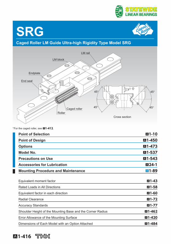
SRG Caged Roller LM Guide Ultra-high Rigidity Type Model SRG
End seal
Endplate
LM block
LM rail
Caged rollerRoller
Cross section
45°
45° 45°
45°
* For the caged roller, see A1-412 .
Point of Selection A1-10 Point of Design A1-450 Options A1-473 Model No. A1-537 Precautions on Use A1-543 Accessories for Lubrication A24-1 Mounting Procedure and Maintenance B1-89
Equivalent moment factor A1-43
Rated Loads in All Directions A1-58
Equivalent factor in each direction A1-60
Radial Clearance A1-72
Accuracy Standards A1-77
Shoulder Height of the Mounting Base and the Corner Radius A1-462
Error Allowance of the Mounting Surface A1-420
Dimensions of Each Model with an Option Attached A1-484
A1-417
LM G
uideSRG
Structure and Features
SRN is an ultra-high rigidity Roller Guide that uses roller cages to allow low-friction, smooth motion and achieve long-term maintenance-free operation.
[Ultra-high Rigidity] A higher rigidity is achieved by using highly rigid rollers as the rolling elements and having the over-all roller length more than 1.5 times greater than the roller diameter.
[4-way Equal Load] Since each row of rollers is arranged at a contact angle of 45so that the LM block receives an equal load rating in all four directions (radial, reverse radial and lateral directions), high rigidity is ensured in all directions.
[Smooth Motion through Skewing Prevention] The roller cage allows rollers to form an evenly spaced line while circulating, thus preventing the roll-ers from skewing as the block enters an loaded area. As a result, fl uctuation of the rolling resistance is minimized, and stable, smooth motion is achieved.
[Long-term Maintenance-free Operation] Use of roller cages eliminates friction between rollers and increases grease retention, enabling long-term maintenance-free operation to be achieved.
[Global Standard Size] SRG is designed to have dimensions almost the same as that of Full Ball LM Guide model HSR, which THK as a pioneer of the linear motion system has developed and is practically a global stan-dard size.

A1-418
Types and Features
Models SRG-15A, 20A Specifi cation Table⇒A1-422 The fl ange of the LM block has tapped holes. Can be mounted from the top or the bottom.
Model SRG-20LA Specifi cation Table⇒A1-422 The LM block has the same cross-sectional shape as model SRG-A, but has a longer overall LM block length (L) and a greater rated load.
Model SRG-C Specifi cation Table⇒A1-422 The fl ange of the LM block has tapped holes. Can be mounted from the top or the bottom. Used in places where the table cannot have through holes for mounting bolts.
A1-419
LM G
uideSRG
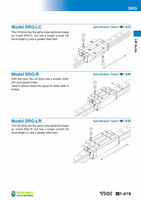
Model SRG-LC Specifi cation Table⇒A1-422
The LM block has the same cross-sectional shape as model SRG-C, but has a longer overall LM block length (L) and a greater rated load.
Model SRG-R Specifi cation Table⇒A1-426 With this type, the LM block has a smaller width (W) and tapped holes. Used in places where the space for table width is limited.
Model SRG-LR Specifi cation Table⇒A1-426 The LM block has the same cross-sectional shape as model SRG-R, but has a longer overall LM block length (L) and a greater rated load.
A1-420
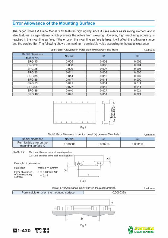
Error Allowance of the Mounting Surface
The caged roller LM Guide Model SRG features high rigidity since it uses rollers as its rolling element and it also features a cage-retainer which prevents the rollers from skewing. However, high machining accuracy is required in the mounting surface. If the error on the mounting surface is large, it will affect the rolling resistance and the service life. The following shows the maximum permissible value according to the radial clearance.
Table1 Error Allowance in Parallelism (P) between Two Rails Unit: mm
Radial clearance Normal C1 C0 Model No. SRG 15 0.005 0.003 0.003 SRG 20 0.008 0.006 0.004 SRG 25 0.009 0.007 0.005 SRG 30 0.011 0.008 0.006 SRG 35 0.014 0.010 0.007 SRG 45 0.017 0.013 0.009 SRG 55 0.021 0.014 0.011 SRG 65 0.027 0.018 0.014 SRG 85 0.040 0.027 0.021
SRG 100 0.045 0.031 0.024
Tole
ranc
e
for p
aral
lelis
m P
Fig.1
Table2 Error Allowance in Vertical Level (X) between Two Rails Unit: mm
Radial clearance Normal C1 C0 Permissible error on the
mounting surface X 0.00030a 0.00021a 0.00011a
Error allowance of the mounting surface
when a = 500mm Rail span
Example of calculation
: Level difference on the block mounting surface : Level difference on the rail mounting surface +X2 X=X1
X2
a X1 500 × 0.0003
X2
X1
= 0.15 X =
Fig.2
Table3 Error Allowance in Level (Y) in the Axial Direction Unit: mm
Permissible error on the mounting surface 0.000036b
b
Y
Fig.3

A1-421
LM G
uideSRG
Model number coding
A1-422
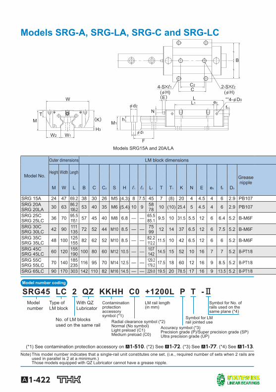
Models SRG-A, SRG-LA, SRG-C and SRG-LC
Models SRG15A and 20A/LA
W
TM
W1W2
F
N
M1h
φ d1
φ d2L1L
C4-S×ℓ1
B
2-S×ℓ2
(φ H)(φ H)
(K)
C2
(E) **4-φ D0
H3
e0
f0
Model No.
Outer dimensions LM block dimensions
Height Width Length Grease nipple
M W L B C C 2 S H ℓ 1 ℓ 2 L 1 T T 1 K N E e 0 f 0 D 0
SRG 15A 24 47 69.2 38 30 26 M5 (4.3) 8 7.5 45 7 (8) 20 4 4.5 4 6 2.9 PB107 SRG 20A SRG 20LA 30 63 86.2
106.2 53 40 35 M6 (5.4) 10 9 58 78 10 (10) 25.4 5 4.5 4 6 2.9 PB107
SRG 25C SRG 25LC 36 70 95.5
115.1 57 45 40 M8 6.8 — — 65.5 85.1 9.5 10 31.5 5.5 12 6 6.4 5.2 B-M6F
SRG 30C SRG 30LC 42 90 111
135 72 52 44 M10 8.5 — — 75 99 12 14 37 6.5 12 6 7.5 5.2 B-M6F
SRG 35C SRG 35LC 48 100 125
155 82 62 52 M10 8.5 — — 82.2 112.2 11.5 10 42 6.5 12 6 6 5.2 B-M6F
SRG 45C SRG 45LC 60 120 155
190 100 80 60 M12 10.5 — — 107 142 14.5 15 52 10 16 7 7 5.2 B-PT1/8
SRG 55C SRG 55LC 70 140 185
235 116 95 70 M14 12.5 — — 129.2 179.2 17.5 18 60 12 16 9 8.5 5.2 B-PT1/8
SRG 65LC 90 170 303 142 110 82 M16 14.5 — — 229.8 19.5 20 78.5 17 16 9 13.5 5.2 B-PT1/8
Symbol for LM rail jointed use
LM rail length(in mm)
With QZLubricator
Contamination protectionaccessory symbol (*1)
Accuracy symbol (*3)Precision grade (P)/Super precision grade (SP)Ultra precision grade (UP)
Radial clearance symbol (*2)Normal (No symbol)Light preload (C1)Medium preload (C0)
No. of LM blocksused on the same rail
Type ofLM block
Model number
Symbol for No. of rails used on the same plane (*4)
SRG45 LC 2 QZ KKHH C0 +1200L P T -Ⅱ
(*1) See contamination protection accessory on A1-510 . (*2) See A1-72 . (*3) See A1-77 . (*4) See A1-13 . Note) This model number indicates that a single-rail unit constitutes one set. (i.e., required number of sets when 2 rails are
used in parallel is 2 at a minimum.) Those models equipped with QZ Lubricator cannot have a grease nipple.
A1-423
LM G
uideSRG
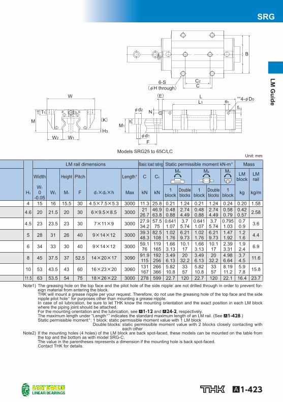
Unit: mm
LM rail dimensions Basic load rating Static permissible moment kN-m * Mass
Width Height Pitch Length * C C 0 M A M B M C LM
block LM rail
H 3 W 1 0
-0.05 W 2 M 1 F d 1 ×d 2 ×h Max kN kN 1
block Double blocks
1 block
Double blocks
1 block kg kg/m
4 15 16 15.5 30 4.5×7.5×5.3 3000 11.3 25.8 0.21 1.24 0.21 1.24 0.24 0.20 1.58
4.6 20 21.5 20 30 6×9.5×8.5 3000 21 26.7
46.9 63.8
0.48 0.88
2.74 4.49
0.48 0.88
2.74 4.49
0.58 0.79
0.42 0.57 2.58
4.5 23 23.5 23 30 7×11×9 3000 27.9 34.2
57.5 75
0.641 1.07
3.7 5.74
0.641 1.07
3.7 5.74
0.795 1.03
0.7 0.9 3.6
5 28 31 26 40 9×14×12 3000 39.3 48.3
82.5 108
1.02 1.76
6.21 9.73
1.02 1.76
6.21 9.73
1.47 1.92
1.2 1.6 4.4
6 34 33 30 40 9×14×12 3000 59.1 76
119 165
1.66 3.13
10.1 17
1.66 3.13
10.1 17
2.39 3.31
1.9 2.4 6.9
8 45 37.5 37 52.5 14×20×17 3090 91.9 115
192 256
3.49 6.13
20 32.2
3.49 6.13
20 32.2
4.98 6.64
3.7 4.5 11.6
10 53 43.5 43 60 16×23×20 3060 131 167
266 366
5.82 10.8
33 57
5.82 10.8
33 57
8.19 11.2
5.9 7.8 15.8
11.5 63 53.5 54 75 18×26×22 3000 278 599 22.7 120 22.7 120 22.1 16.4 23.7
Models SRG25 to 65C/LC
6-S(φ H through)
W
(K) M
T T1
W1 W2
C2
L1
C
L (E) e0
f0 φ d2
φ d1
M1
F
h
N
B
**4-φ D0
H3
Note1) The greasing hole on the top face and the pilot hole of the side nipple * are not drilled through in order to prevent for-eign material from entering the block. THK will mount a grease nipple per your request. Therefore, do not use the greasing hole of the top face and the side nipple pilot hole * for purposes other than mounting a grease nipple. In case of oil lubrication, be sure to let THK know the mounting orientation and the exact position in each LM block where the piping joint should be attached. For the mounting orientation and the lubrication, see A1-12 and A24-2 , respectively. The maximum length under “Length * ” indicates the standard maximum length of an LM rail. (See A1-428 .) Static permissible moment * : 1 block: static permissible moment value with 1 LM block
Double blocks: static permissible moment value with 2 blocks closely contacting with each other
Note2) If the mounting holes (4 holes) of the LM block are back spot-faced, these models can be mounted on the table from the top and the bottom as with model SRG-C. The value in the parentheses represents a dimension if the mounting hole is back spot-faced. Contact THK for details.
Model number coding
A1-424
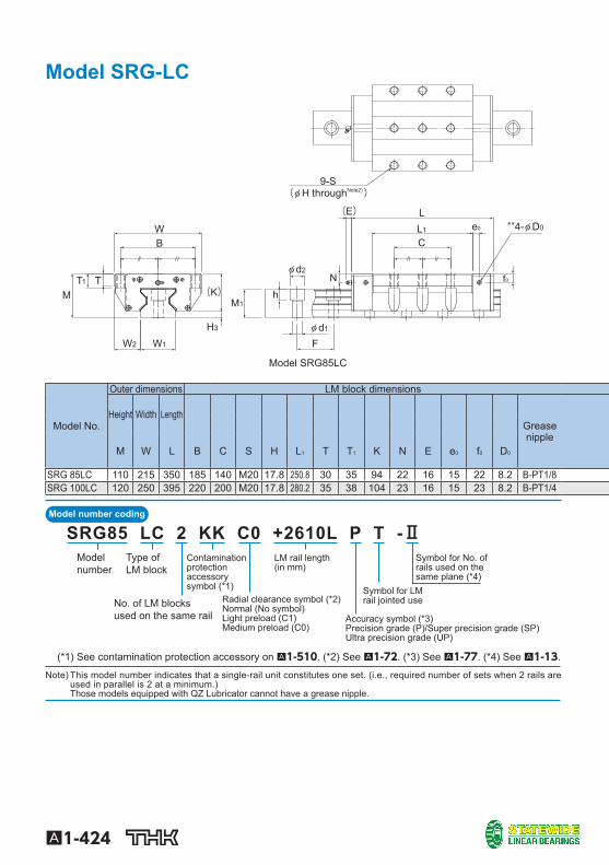
Model SRG-LC
Model SRG85LC
(φ H throughNote2))
(K)
W1
H3
W2
MT1
WB
T
LL1
Ce0
φ d2
hN
M1
φ d1
F
9-S
(E)
f0
**4-φ D0
Model No.
Outer dimensions LM block dimensions
Height Width Length Grease nipple
M W L B C S H L 1 T T 1 K N E e 0 f 0 D 0
SRG 85LC 110 215 350 185 140 M20 17.8 250.8 30 35 94 22 16 15 22 8.2 B-PT1/8 SRG 100LC 120 250 395 220 200 M20 17.8 280.2 35 38 104 23 16 15 23 8.2 B-PT1/4
LM rail length(in mm)
Contamination protectionaccessory symbol (*1)
Accuracy symbol (*3)Precision grade (P)/Super precision grade (SP)Ultra precision grade (UP)
Radial clearance symbol (*2)Normal (No symbol)Light preload (C1)Medium preload (C0)
No. of LM blocksused on the same rail
Type ofLM block
Model number
Symbol for LM rail jointed use
Symbol for No. of rails used on the same plane (*4)
SRG85 LC 2 KK C0 +2610L P T -Ⅱ
(*1) See contamination protection accessory on A1-510 . (*2) See A1-72 . (*3) See A1-77 . (*4) See A1-13 .
Note) This model number indicates that a single-rail unit constitutes one set. (i.e., required number of sets when 2 rails are used in parallel is 2 at a minimum.) Those models equipped with QZ Lubricator cannot have a grease nipple.
A1-425
LM G
uideSRG
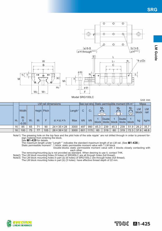
Model SRG100LC
(φ H throughNote3)) (φ HNote3))
(K)
W1
H3
W2
MT1
WB
T
LL1
Ce0
φ d2
hN
M1
φ d1
F
(a)6-S (b)3-S
(E)
f0
*4-φ D0
Unit: mm LM rail dimensions Basic load rating Static permissible moment kN-m * Mass
Width Height Pitch Length * C C 0 M A M B M C LM
block LM rail
H 3 W 1 0
-0.05 W 2 M 1 F d 1 ×d 2 ×h Max kN kN 1
block Double blocks
1 block
Double blocks
1 block kg kg/m
16 85 65 71 90 24×35×28 3000 497 990 45.3 239 45.3 239 51.9 26.2 35.7 16 100 75 77 105 26×39×32 3000 601 1170 60 319 60 319 72.3 37.6 46.8
Note1) The greasing hole on the top face and the pilot hole of the side nipple ** are not drilled through in order to prevent for-eign material from entering the block. See A1-429 for details. The maximum length under “Length * ” indicates the standard maximum length of an LM rail. (See A1-428 .) Static permissible moment * : 1 block: static permissible moment value with 1 LM block
Double blocks: static permissible moment value with 2 blocks closely contacting with each other
The removing/mounting jig is not provided as standard. When desiring to use it, contact THK. Note2) The LM block mounting holes (9 holes) of SRG85LC are all through holes (full thread). Note3) The LM block mounting holes in part (a) (6 holes) of SRG100LC are through holes (full thread).
The LM block mounting holes in part (b) (3 holes) have effective thread depth of 22 mm.
Model number coding
A1-426
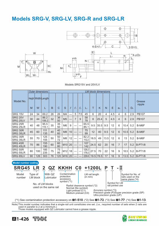
Models SRG-V, SRG-LV, SRG-R and SRG-LR
Models SRG15V and 20V/LV
**4-φ D0
B
F
N
M1
φ d1
φ d2L1
L
C 2-S×ℓ24-S×ℓ1
(E)
h T
W
W1 W2
M (K)
H3
e0
f0
Model No.
Outer dimensions LM block dimensions
Height Width Length Grease nipple
M W L B C S ℓ ℓ 1 ℓ 2 L 1 T K N E e 0 f 0 D 0
SRG 15V 24 34 69.2 26 26 M4 — 5 7.5 45 6 20 4 4.5 4 6 2.9 PB107 SRG 20V SRG 20LV 30 44 86.2
106.2 32 36 50 M5 — 7 9 58
78 8 25.4 5 4.5 4 6 2.9 PB107
SRG 25R SRG 25LR 40 48 95.5
115.1 35 35 50 M6 9 — — 65.5
85.1 9.5 35.5 9.5 12 6 10.4 5.2 B-M6F
SRG 30R SRG 30LR 45 60 111
135 40 40 60 M8 10 — — 75
99 12 40 9.5 12 6 10.5 5.2 B-M6F
SRG 35R SRG 35LR 55 70 125
155 50 50 72 M8 12 — — 82.2
112.2 18.5 49 13.5 12 6 13 5.2 B-M6F
SRG 45R SRG 45LR 70 86 155
190 60 60 80 M10 20 — — 107
142 24.5 62 20 16 7 17 5.2 B-PT1/8
SRG 55R SRG 55LR 80 100 185
235 75 75 95 M12 18 — — 129.2
179.2 27.5 70 22 16 9 18.5 5.2 B-PT1/8
SRG 65LV 90 126 303 76 120 M16 20 — — 229.8 19.5 78.5 17 16 9 13.5 5.2 B-PT1/8
LM rail length(in mm)
With QZLubricator
Contamination protectionaccessory symbol (*1)
Accuracy symbol (*3)Precision grade (P)/Super precision grade (SP)Ultra precision grade (UP)
Radial clearance symbol (*2)Normal (No symbol)Light preload (C1)Medium preload (C0)
No. of LM blocksused on the same rail
Type ofLM block
Model number
Symbol for LM rail jointed use
Symbol for No. of rails used on the same plane (*4)
SRG45 LR 2 QZ KKHH C0 +1200L P T -Ⅱ
(*1) See contamination protection accessory on A1-510 . (*2) See A1-72 . (*3) See A1-77 . (*4) See A1-13 . Note) This model number indicates that a single-rail unit constitutes one set. (i.e., required number of sets when 2 rails are
used in parallel is 2 at a minimum.) Those models equipped with QZ Lubricator cannot have a grease nipple.
A1-427
LM G
uideSRG
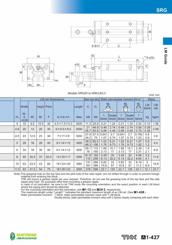
Unit: mm
LM rail dimensions Basic load rating Static permissible moment kN-m * Mass
Width Height Pitch Length * C C 0 M A M B M C LM
block LM rail
H 3 W 1 0
-0.05 W 2 M 1 F d 1 ×d 2 ×h Max kN kN 1
block Double blocks
1 block
Double blocks
1 block kg kg/m
4 15 9.5 15.5 30 4.5×7.5×5.3 3000 11.3 25.8 0.21 1.24 0.21 1.24 0.24 0.15 1.58
4.6 20 12 20 30 6×9.5×8.5 3000 21 26.7
46.9 63.8
0.48 0.88
2.74 4.49
0.48 0.88
2.74 4.49
0.58 0.79
0.28 0.38 2.58
4.5 23 12.5 23 30 7×11×9 3000 27.9 34.2
57.5 75
0.641 1.07
3.7 5.74
0.641 1.07
3.7 5.74
0.795 1.03
0.6 0.8 3.6
5 28 16 26 40 9×14×12 3000 39.3 48.3
82.5 108
1.02 1.76
6.21 9.73
1.02 1.76
6.21 9.73
1.47 1.92
0.9 1.2 4.4
6 34 18 30 40 9×14×12 3000 59.1 76
119 165
1.66 3.13
10.1 17
1.66 3.13
10.1 17
2.39 3.31
1.6 2.1 6.9
8 45 20.5 37 52.5 14×20×17 3090 91.9 115
192 256
3.49 6.13
20 32.2
3.49 6.13
20 32.2
4.98 6.64
3.2 4.1 11.6
10 53 23.5 43 60 16×23×20 3060 131 167
266 366
5.82 10.8
33 57
5.82 10.8
33 57
8.19 11.2
5 6.9 15.8
11.5 63 31.5 54 75 18×26×22 3000 278 599 22.7 120 22.7 120 22.1 12.1 23.7
Models SRG25 to 65R/LR/LV
W
(K) M
T
W1 W2
L1
L
B
(E) e0
f0 φ d2
**4-φ D0
φ d1
M1
F
N
h
6-S×ℓ C
H3
Note) The greasing hole on the top face and the pilot hole of the side nipple * are not drilled through in order to prevent foreign material from entering the block. THK will mount a grease nipple per your request. Therefore, do not use the greasing hole of the top face and the side nipple pilot hole* for purposes other than mounting a grease nipple. In case of oil lubrication, be sure to let THK know the mounting orientation and the exact position in each LM block where the piping joint should be attached. For the mounting orientation and the lubrication, see A1-12 and A24-2 , respectively. The maximum length under “Length * ” indicates the standard maximum length of an LM rail. (See A1-428 .) Static permissible moment * : 1 block: static permissible moment value with 1 LM block
Double blocks: static permissible moment value with 2 blocks closely contacting with each other
A1-428
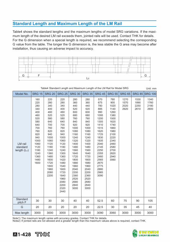
Standard Length and Maximum Length of the LM Rail
Table4 shows the standard lengths and the maximum lengths of model SRG variations. If the maxi-mum length of the desired LM rail exceeds them, jointed rails will be used. Contact THK for details. For the G dimension when a special length is required, we recommend selecting the corresponding G value from the table. The longer the G dimension is, the less stable the G area may become after installation, thus causing an adverse impact to accuracy.
G F L0
G
Table4 Standard Length and Maximum Length of the LM Rail for Model SRG Unit: mm
Model No. SRG 15 SRG 20 SRG 25 SRG 30 SRG 35 SRG 45 SRG 55 SRG 65 SRG 85 SRG 100
LM railstandard
length (L O )
160 220 280 340 400 460 520 580 640 700 760 820 940
1000 1060 1120 1180 1240 1360 1480 1600
220 280 340 400 460 520 580 640 700 760 820 940
1000 1060 1120 1180 1240 1360 1480 1600 1720 1840 1960 2080 2200
220 280 340 400 460 520 580 640 700 760 820 940
1000 1060 1120 1180 1240 1300 1360 1420 1480 1540 1600 1720 1840 1960 2080 2200 2320 2440
280 360 440 520 600 680 760 840 920
1000 1080 1160 1240 1320 1400 1480 1560 1640 1720 1800 1880 1960 2040 2200 2360 2520 2680 2840 3000
280 360 440 520 600 680 760 840 920
1000 1080 1160 1240 1320 1400 1480 1560 1640 1720 1800 1880 1960 2040 2200 2360 2520 2680 2840 3000
570 675 780 885 990
1095 1200 1305 1410 1515 1620 1725 1830 1935 2040 2145 2250 2355 2460 2565 2670 2775 2880 2985 3090
780 900 1020 1140 1260 1380 1500 1620 1740 1860 1980 2100 2220 2340 2460 2580 2700 2820 2940 3060
1270 1570 2020 2620
1530 1890 2250 2610
1340 1760 2180 2600
Standard pitch F 30 30 30 40 40 52.5 60 75 90 105
G 20 20 20 20 20 22.5 30 35 45 40
Max length 3000 3000 3000 3000 3000 3090 3060 3000 3000 3000
Note1) The maximum length varies with accuracy grades. Contact THK for details. Note2) If jointed rails are not allowed and a greater length than the maximum values above is required, contact THK.

A1-429
LM G
uideSRG
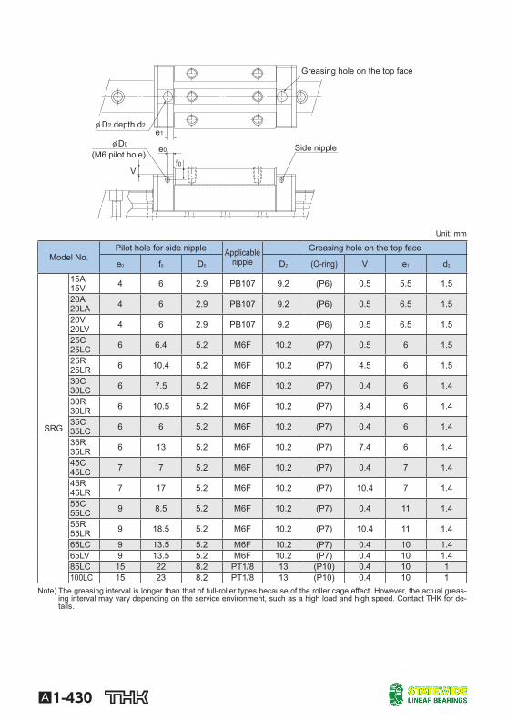
Greasing Hole [Greasing Hole for Model SRG] Model SRG allows lubrication from both the side and top faces of the LM block. The greasing hole of standard types is not drilled through in order to prevent foreign material from entering the LM block. When using the greasing hole, contact THK. When using the greasing hole on the top face of models SRG-R and SRG-LR, a greasing adapter is separately required. Contact THK for details. If the mounting orientation of the LM Guide is other than horizontal use, the lubricant may not reach the raceway completely. Be sure to let THK know the mounting orientation and the exact position in each LM block where the grease nipple or the piping joint should be attached. For the mounting orientation and the lubrication, see A1-12 and A24-2 , respectively.
A1-430
Side nipple
Greasing hole on the top face
(M6 pilot hole)
φ D2 depth d2
V
φ D0
f0e0
e1
Unit: mm
Model No. Pilot hole for side nipple Applicable
nipple Greasing hole on the top face
e 0 f 0 D 0 D 2 (O-ring) V e 1 d 2
SRG
15A 15V 4 6 2.9 PB107 9.2 (P6) 0.5 5.5 1.5
20A 20LA 4 6 2.9 PB107 9.2 (P6) 0.5 6.5 1.5
20V 20LV 4 6 2.9 PB107 9.2 (P6) 0.5 6.5 1.5
25C 25LC 6 6.4 5.2 M6F 10.2 (P7) 0.5 6 1.5
25R 25LR 6 10.4 5.2 M6F 10.2 (P7) 4.5 6 1.5
30C 30LC 6 7.5 5.2 M6F 10.2 (P7) 0.4 6 1.4
30R 30LR 6 10.5 5.2 M6F 10.2 (P7) 3.4 6 1.4
35C 35LC 6 6 5.2 M6F 10.2 (P7) 0.4 6 1.4
35R 35LR 6 13 5.2 M6F 10.2 (P7) 7.4 6 1.4
45C 45LC 7 7 5.2 M6F 10.2 (P7) 0.4 7 1.4
45R 45LR 7 17 5.2 M6F 10.2 (P7) 10.4 7 1.4
55C 55LC 9 8.5 5.2 M6F 10.2 (P7) 0.4 11 1.4
55R 55LR 9 18.5 5.2 M6F 10.2 (P7) 10.4 11 1.4
65LC 9 13.5 5.2 M6F 10.2 (P7) 0.4 10 1.4 65LV 9 13.5 5.2 M6F 10.2 (P7) 0.4 10 1.4 85LC 15 22 8.2 PT1/8 13 (P10) 0.4 10 1 100LC 15 23 8.2 PT1/8 13 (P10) 0.4 10 1
Note) The greasing interval is longer than that of full-roller types because of the roller cage effect. However, the actual greas-ing interval may vary depending on the service environment, such as a high load and high speed. Contact THK for de-tails.