calculated and flight-measured handling-qualities factors of … · calculated and flight-measured...
TRANSCRIPT

NASA TECHNICAL NOTE
CALCULATED AND FLIGHT-MEASURED HANDLING-QUALITIES FACTORS OF THREE SUBSONIC JET TRANSPORTS
by WaZtev E, McNeiZZ ?
3 Ames Research Center I Y C
Moffett Field, CaZzy
NATIONAL AERONAUTICS AND SPACE ADMINISTRATION WASHINGTON, D. C. NOVEMBER 1 9 6 8
https://ntrs.nasa.gov/search.jsp?R=19690001164 2019-06-15T09:24:53+00:00Z
TECH LIBRARY KAFB, NM
I llllll lllll lllll 11111 1 lllll I Ill1 Ill1 013Lb37
NASA T N D-4832
CALCULATED AND FLIGHT-MEASURED HANDLING-QUALITIES
FACTORS OF THREE SUBSONIC J E T TRANSPORTS
By Walter E . McNeill
A m e s Research Center Moffett Field, Calif.
N A T I O N A L AERONAUTICS AND SPACE ADMINISTRATION ~
For sole by the Clearinghouse for Federal Scientific and Technica l Information Springfield, Virginia 22151 - C F S T I pr ice $3.00

CALCULATED AND FLIGHT-MEASPJD HANDLING-QUALITIES
FACTORS OF THREE SUBSONIC JET TRANSPORTS
By Walter E. McNeill
Ames Research Center
SUMMARY
As p a r t o f anNASA in t e rcen te r study of j e t t ranspor t s t a b i l i t y and cont ro l problems i n severe turbulence, severa l calculated and flight-measured handling-qualit ies f a c t o r s of t h ree current j e t t ranspor t s have been reviewed, and compared with various handl ing-qual i t ies c r i t e r i a .
The longi tudinal and lateral handling-qualit ies parameters w e r e ca lcu la ted by means of a d i g i t a l computer program, f o r s eve ra l t y p i c a l f l i g h t conditions within t h e normal operating envelopes, using aerodynamic and physi- c a l da t a supplied by t h e manufacturers of t he a i r c r a f t as t h e most r e l i a b l e information avai lable . The ca lcu la t ions did not take account of e f f e c t s of yaw dampers and automatic p i t c h t r i m devices.
On t h e bas i s of t h e cur ren t mi l i t a ry spec i f ica t ion and o ther published c r i t e r i a , a l l t h ree t ranspor t s had s a t i s f a c t o r y or acceptable predicted o r f l i g h t -measured longi tudina l short-period frequency and damping charac te r i s - t i c s i n t h e f l i g h t conditions of i n t e r e s t . Ekcept f o r some cases of speed i n s t a b i l i t y associated with disengagement of Mach trim compensation devices, acceptable longi tudinal phugoid cha rac t e r i s t i c s a l s o were calculated f o r these t ranspor t s . i s t i c s var ied from s a t i s f a c t o r y f o r normal operation t o unacceptable with dampers inoperative. According t o the current m i l i t a r y spec i f ica t ion , t h e predicted r o l l cont ro l c h a r a c t e r i s t i c s were general ly acceptable f o r two of t h e th ree t ranspor t s .
The l a t e r a l - d i r e c t i o n a l o s c i l l a t o r y (Dutch roll) character-
INTRODUCTION
I n recent years , s eve ra l l a rge j e t t ranspor t a i r c r a f t have suffered loss of cont ro l during scheduled operation. In some cases , recovery w a s not e f fec ted and des t ruc t ion of t h e a i rp lane resul ted. I n addi t ion t o t h e c l a s s of a i rp lane , these incidents had two f a c t o r s i n cormnon: t h e a i r c r a f t were being operated under instrument conditions and i n severe storm turbulence.
I n December 1963, a cooperative NASA study w a s i n i t i a t e d , involving research teams from t h e Ames , Langley, and Fl ight Research Centers, t o inves- t i g a t e a l l per t inent aspects of t h i s problem. Reference 1 summarizes t h e ove ra l l program and presents some of t h e key observations r e su l t i ng from a l imi ted analysis at t h e Ames Research Center of t h e handling q u a l i t i e s of t h ree current je t t r anspor t s .

I n t h i s repor t , t he r e s u l t s of t he handl ing-qual i t ies ana lys i s a r e discussed i n grea te r d e t a i l and i n terms of ex i s t ing or recommended numerical c r i t e r i a . Comparisons of the calculated c h a r a c t e r i s t i c s with these c r i t e r i a a r e not used as bases for conclusions as t o t h e accep tab i l i t y of a given a i r - plane because of inconsis tencies among some of t h e c r i t e r i a and a lack of c l e a r l y es tabl ished app l i cab i l i t y of t he c r i t e r i a t o the je t upsets . Rather, the c r i t e r i a a r e included t o provide a s t ruc tu re f o r presentat ion of represen- t a t i v e behavior and t o serve as ind ica tors of gross inadequacies. Some comparisons between computed cha rac t e r i s t i c s and f l i g h t measurements a r e a l so included .
NOTATION
2P wing span, f t C
wing mean aerodynamic chord, C ‘sa f t
drag drag coef f ic ien t ,
- acD aM
l i f t l i f t coef f ic ien t , -
%S ac, 1 &- ’ rad
1 acL - ’ rad
czgr
C lP
C ‘r
mse C
cmM
rolling-moment coef f ic ien t , r o l l i n g moment
%Sb
1 - - dp ’ rad
ac 2 1 - - as, ’ rad
d(pb/2V) ’ rad
2 1 - d(rb/2V) ’ rad
pitching-moment coe f f i c i en t , p i tch ing moment
qmSF
acm 1 -,rad
2

yawing-moment coe f f i c i en t , yawing moment
%Sb
acn 1 ap ' rad
acn 1 as, ' rad
- -
- -
acn 1 - - 36, ' rad
side-force coe f f i c i en t , s ide force
sas acY 1
acY 1
acY 1
- - a p ' rad
- - as, ' rad
- - as, ' rad
a c Y 1
acY 1 "rad
a(pb/2V) ' rad
cycles t o damp t o 1/10 amplitude
cycles t o damp t o 1/2 amplitude
undamped na tura l frequency of longi tudina l shor t - period mode, cps
pressure a l t i t u d e , f t
ro l l i ng , pi tching, and yaw- ing moments of i n e r t i a , respect ively, about body reference axes, slug-ft"
product of i n e r t i a about body reference axes, s lug -f t2
constant r e l a t i n g damping c r i t e r i o n t o
Mach number
m a x i m u m permitted Mach number f o r normal opera- t i on , m i l i t a r y and c i v i l a i r c r a f t , respec t ive ly
normal acce lerat ion, po s i - t i v e upward, g
, an, - ha
r o l l i n g angular veloci ty , rad/sec
($s,,, s t a t e wing -t i p he l ix m a x i m u m a t t a inab le steady-
angle, rad
&! , rad/sec2 d t
maximum a t t a inab le r o l l i n g acce lera t ion , r ad/s ec2 *,ax
Dutch roll o s c i l l a t i o n period, sec 'd
longi tudina l phugoid o s c i l l a t i o n period, sec 'PH
3
q
4,
r
S
S
T
a T
p i tch ing angular ve loc i ty , Go trimmed angle of a t tack , rad/ s ec
dynamic pres sure, lb/f t2 P angle of s ide s l i p , radians
yawing angular ve loc i ty , rad/sec Yo trimmed longi tudinal f l i g h t -
pa th inc l ina t ion , pos i t i ve for climb, deg complex frequency
(Laplace operator) &a t o t a l a i l e ron def lec t ion , pos i t i ve f o r r i g h t a i l e r o n down, radians wing reference area, ft2
Ee e leva tor def lect ton, posi- tive t r a i l i n g edge down, radians
thrust, l b
va r i a t ion of t h r u s t with Mach number at trim condition, l b
aM
T1/2, d
‘i/z ,PH
6, rudder def lect ion, pos i t i ve t r a i l i n g edge l e f t , radians
Dutch roll time t o damp t o half a m p l i - tude, sec
damping r a t i o of t he o s c i l l a t o r y Dutch roll, ’ (PH’ SP longi tudinal phugoid, .
and longi tudinal shor t - period modes, respec t ive ly
phugoid time t o damp t o half amplitude, sec
s ing le -degree -of -freedom T% roll time constant, sec t
V
VC
time, sec
t r u e airspeed, f t / s e c T roll-subsidence mode time R3 constant, sec
ca l ib ra t ed airspeed, knots
TS s p i r a l mode time constant, sec
cp bank angle, radians Ve equivalent airspeed, knots or f t / s e c
r a t i o of bank amplitude t o s i d e s l i p amplitude i n the
mode
Id - Id o s c i l l a t o r y Dutch roll
maximum permitted ca l ibra ted airspeed f o r normal operation, knots
angle of a t tack , radians a
4
Wn7PH, undamped na tu ra l frequency of the o s c i l l a t o r y Dutch roll, longi tudina l phugoid, and longi tudina l short -period modes, re spec t ive l y , r ad/s e c
'"n, SP I- frequency of t h e o s c i l l a t o r y p a r t of t he numerator of the cp
"CP t r a n s f e r funct ion, rad/sec E a
METHOD
Computation
Computation of the s t a b i l i t y , control , and handling-qualit ies fact0r.s of i n t e r e s t w a s based on equations of motion t h a t included a l l six a i rp lane degrees of freedom. The equations were l i n e a r and per turbat ions i n ve loc i t i e s and angles were assumed s m a l l . The ca lcu la t ions were performed by d i g i t a l computer programs (here inaf te r r e fe r r ed t o as the "exact f ac to r s " programs) ,l which t r ea t ed the longi tudina l and the l a t e ra l -d i r ec t iona l s e t s of equations separately. The programs were wr i t t en i n Fortran N computer language.
Input D a t a
The aerodynamic s t a b i l i t y der ivat ives , mass and i n e r t i a parameters, and dimensional data f o r each a i rp lane and f l i g h t condition were based l a rge ly on wind-tunnel measurements supplemented by f l i g h t t e s t s , and were represented by the a i r c r a f t manufacturers as the most r e l i a b l e da ta ava i lab le for use i n developing opera t iona l f l i g h t simulators. Theoret ical estimates were given f o r parameters t h a t did not lend themselves t o ready experimental measurement (e .g . , most of t he r o t a r y de r iva t ives ) . frame f l e x i b i l i t y were included i n the data . Yaw dampers and automatic p i t c h t r im devices were assumed inoperat ive.
Corrections f o r t he e f f e c t s of air-
The major dimensions of t he j e t t ranspor t s a r e given i n t a b l e I. The bas ic f l i g h t conditions analyzed are tabulated below.
Condition Vc, knots M Alt i tude, f t
Climb 280 0.46 5,000 Climb 285 0.62 20,000 Cruise 216 - 250 0.72 - 0.82 40,000 C r u i s e 264 - 295 0.78 - 0.86 35 , 000 Maxi" VN0 376 - 397 0.844 - 0.90 22,400 - 23,500 Holding 225 - 240 0.45 - 0.48 15,000
The a l t i t u d e s and ca l ib ra t ed airspeeds f o r t h e bas ic f l i g h t conditions a re compared with t h e operat ional f l i g h t envelopes i n f i g u r e 1. Because a l l t h e reported upsets occurred at higher speeds, t h e take-off and landing
Contract NM2-864.
- lFurnished by- Systems Technology, Inc., Hawthorne, Cal i fornia , under
5

.. .. -..- .----.. I.., ... I.. ..... .... ..---_._._____.-.___ ~
conditions w e r e not considered. The values f o r a l l input parameters corre- sponding t o six bas ic f l i g h t conditions are presented i n t a b l e 11. addi t iona l conditions, which c lose ly approximated conditions f o r which f l i g h t d a t a were ava i lab le , were s e t up f o r computation. described i n f i g u r e 2 and t a b l e 111.
Four
These conditions are
Output D a t a
The results obtained d i r e c t l y from t h e d i g i t a l programs were i n t h e form of (1) t h e roots of t h e c h a r a c t e r i s t i c equation (where complex roots were obtained, they were expressed as na tu ra l frequency and damping r a t i o ) , and (2) t h e numerator roots (zeros) and gains of se lec ted a i rp lane t r a n s f e r func- t i o n s . One parameter of i n t e r e s t , t h e bank-to-sideslip r a t i o lCp]/lpl of t h e lateral o s c i l l a t o r y (Dutch roll) mode, w a s not computed e x p l i c i t l y i n t h e d i g i t a l program; r a the r , it w a s hand calculated by expressing r a t i o of numerators of bank and s i d e s l i p t r a n s f e r funct ions (e .g . , t h e 'p/6, and p/Sr t r a n s f e r func t ions) wr i t t en as polynomials i n terms of t h e complex frequency s, and evaluated by subs t i t u t ing t h e roots of t h e Dutch roll mode. The r e su l t i ng complex r a t i o w a s converted t o t h e amplitude r a t i o lCpl/lpl by tak ing t h e square root of t h e sum of squares of t h e real and imaginary pa r t s . A l l o ther output data were d i r e c t l y t r a n s l a t a b l e i n t o cur ren t ly applicable handling-qualit ies f ac to r s .
Cp/p as t h e
RESULTS AND DISCUSSION
The longi tudina l and l a t e ra l -d i r ec t iona l handling-qualit ies f ac to r s computed f o r t h e basic conditions a re shown i n t a b l e IV, and i n f igu res 3 through 19. Where appl icable , boundaries ind ica t ing ex i s t ing or proposed handling-qualit ies c r i t e r i a a r e included. These c r i t e r i a a r e indicated f o r comparison purposes only, s ince t h e bui lders of c i v i l t ranspor t s i n the United S ta t e s a re not required t o comply w i t ! any d e f i n i t e numerical standards regarding t h e handling-qualit ies parameters considered herein. They need s a t i s f y only Pa r t 25 of t h e Federal A i r Regulations, t h e FAA c e r t i f i c a t i o n tes t p i l o t , and t h e buyer of t h e airplane.
Although the th ree t ranspor t s have accumulated many thousands of f l i g h t hours, no documented p i l o t comments were ava i lab le f o r inclusion i n t h i s repor t .
The handling-qualit ies f ac to r s computed for t h e addi t iona l f l i g h t conditions ( f o r comparison with f l i g h t measurements) a r e presented i n t a b l e V.
Longitudinal Short-Period Charac te r i s t ics
Basic f l i g h t conditions.- The longi tudinal short-period na tu ra l frequencies and damping r a t i o s are shown i n f i g u r e 3. The cha rac t e r i s t i c s of a l l three airplanes are similar, with between 0.24 and 0.45 cps fn,Sp
6
I

and cSp between 0.33 and 0.65. The present m i l i t a r y spec i f ica t ion (ref. 2 ) is indicated by t h e rectangular-appearing boundaries a t t h e l e f t . This c r i t e r i o n would be s a t i s f i e d i n a11 cases.
Figure 3 a l s o shows pi lot-opinion boundaries from v a r i a b l e - s t a b i l i t y f l i g h t t e s t s by Cornell Aeronautical Laboratory i n a B-26 a i rp lane ( r e f . 3). According t o t h i s c r i t e r i o n , t h e th ree t ranspor t s as a group would cover t h e fu l l range from "best t e s t ed" t o Cornell (refs. 4 and 5) are not used f o r comparison because they were obtained i n tests of a f igh ter - type va r i ab le - s t ab i l i t y a i rp lane , an F-94AY with charac- t e r i s t i c s markedly d i f f e r e n t from those of a t ranspor t . Another analysis of longi tudina l handling q u a l i t i e s resu l ted i n a new set of boundaries i n terms of t h e same two var iab les , short-period na tu ra l frequency and damping r a t i o (ref. 6 ) . This set of boundaries, shown i n f igu re 4, more near ly represents cur ren t thinking among handling-qualit ies inves t iga tors .
More recent pi lot-opinion da ta from
The d i s s i m i l a r i t y i n t h e nature of t h e boundaries from references 2, 3,
E t h e and 6 is of i n t e r e s t . t he period is less than 6 seconds, damping requirements m u s t be met. period is 6 seconds or longer, no damping requirements need be s a t i s f i e d . (The spec i f ica t ion states only t h a t res idua l o s c i l l a t i o n s s h a l l not be of objectionable magnitude. ) ind ica te t h a t , a t a na tu ra l frequency l e s s than 0.29 cps, poor cha rac t e r i s t i c s should be expected regardless of t h e damping r a t i o . disagreement as t o t h e prec ise shape of t he boundaries, t h e proper var iab le t o use as the ordinate , and as t o whether (as indicated by t h e lower boundary of ref. 6 ) increased damping r a t i o can compensate f o r very low na tu ra l frequen- c i e s , a l l recent work shows t h a t t h e low-frequency, low-damping corner should be avoided.
The present mi l i t a ry spec i f i ca t ion says t h a t as long as
On t h e other hand, t h e boundaries of reference 3
Although the re may be
The results of t h e present study, shown i n r e l a t i o n t o t h e proposed boundaries of reference 6 i n f i g u r e 4, ind ica te t h a t most of t h e bas ic f l i g h t conditions would have marginally acceptable cha rac t e r i s t i c s f o r normal opera- t i o n . Exceptions would be t h e m a x i m u m speed case f o r a l l th ree t ranspor t s (which c l e a r l y would be acceptable) and t h e 40,000-foot c ru i se and holding conditions of t ranspor t B (acceptable f o r emergency).
I n f igu res 3 and 4, t h e shaded areas denote short-period dynamics estimated f o r two representa t ive four-engine propeller-driven t ranspor t s i n t h e 100,000 t o l30,OOO-lb weight c l a s s . These cha rac t e r i s t i c s are t y p i c a l of a c l a s s of a i r c r a f t not associated with upset inc idents . With propel ler- driven t ranspor t s , t he consequences of upset ( a l t i t u d e loss and overspeed) would usual ly be l e s s se r ious than with current j e t t ranspor t s . Although t h e short-period damping r a t i o s a re somewhat grea te r f o r these earlier t r anspor t s than f o r t he current jets, t h e frequencies a re at about t h e same l eve l .
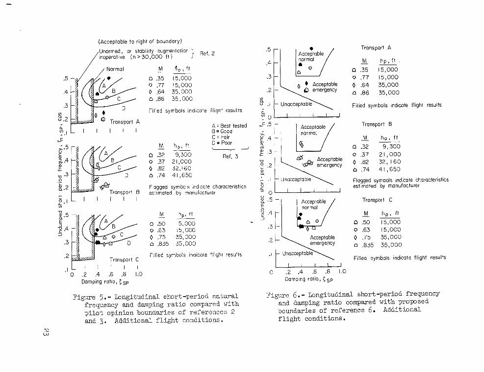
Additional f l i g h t conditions. - Values of t he short-period frequency and damping r a t i o computed and measured (unpublished r e s u l t s of NASA f l i g h t t es t s ) for t he addi t iona l f l i g h t conditions are p lo t t ed i n f igu re 5 . The boundaries of references 2 and 3 are again presented f o r compwison. (No f l i g h t da ta

were ava i l ab le f o r t r anspor t B; ins tead, manufacturer's estimates are shown. The two sets of computed cha rac t e r i s t i c s agree w e l l . )
Agreement between computed and f l i g h t -measured damping of t r anspor t A w a s general ly good. 15,000 f t ) , t h e predicted frequency w a s less than t h a t measured i n f l i g h t . For t ransport C, t h e level of damping calculated w a s consis tent ly g rea t e r than t h a t measured i n f l i g h t ; however, a l l damping values were within what would be considered t h e "good" range.
Previous comments concerning f i g u r e 5 apply here as w e l l .
t h e three t r anspor t s (bas ic conditions only) are indicated i n terms of damping r a t i o and two parameters, proposed i n reference 7, which re la te l i f t or normal accelerat ion cha rac t e r i s t i c s and na tu ra l frequency: &/an f o r nZa< 15 g/rad, and % /un f o r % > 1 5 g/rad. The boundaries separating sa t i s f ac to ry , accep take , and unacceptable areas are from reference 7 and were developed l a rge ly from t h e f l i g h t - t e s t r e s u l t s of references 4, 5, and 8.
shown i n f igures 3 and 4, t h e dynamics i n terms of La/Un and nZa/un f i t , with only one exception, e n t i r e l y within t h e s a t i s f a c t o r y regions i n f i g u r e 7 . The shor t -period cha rac t e r i s t i c s of t h e two reference propel le r t ranspor t s , shown as shaded areas, are a l s o within these s a t i s f a c t o r y regions.
For t h e high-speed condition at each a l t i t u d e ( e spec ia l ly at
Figure 6 shows t h e above comparisons and t h e NADC boundaries ( r e f . 6 ) .
Other frequency parameters.- I n f i g u r e 7 , t h e short-period dynamics of
a
I n cont ras t t o t h e marginal accep tab i l i t y of t h e shor t -period dynamics
Longitudinal Phugoid Character is t ics
p i l o t cont ro l inputs i f t h e period of t h e phugoid mode i s s u f f i c i e n t l y shor t , or by a large-scale atmospheric di.sturbance which i s periodic and of a frequency near t h a t of t h e phugoid. phugoid c h a r a c t e r i s t i c s of t h e three t r anspor t s were examined.
or double amplitude) f o r t h e basic and add i t iona l f l i g h t conditions a re p l o t t e d i n f igu res 8 and 9, respec t ive ly . The values of a / a M given i n t a b l e s I1 and I11 were used i n t h e computations.
Poorly damped or divergent phugoid c h m a c t e r i s t i c s could be exci ted by
For t h i s reason, t h e controls-fixed
Computed values of phugoid period and damping ( r ec ip roca l of t i m e t o ha l f
Existing c r i t e r i a f o r t h e phugoid mode are very general, even f o r mi l i t a ry a i r c r a f t . I n general, i f t h e period i s 15 seconds or grea te r , it i s required only t h a t t h e phugoid not pro-duce "objectionable" f l i g h t cha rac t e r i s - t i c s . and 10, i s t h a t t h e t i m e f o r an unstable o s c i l l a t i o n t o double amplitude s h a l l be 55 seconds or grea te r .
A t a l l f l i g h t conditions where t h e phugoid mode w a s o sc i l l a to ry , t h e above numerical c r i t e r i o n was s a t i s f i e d . Solut ion of t h e longi tudinal equa- t i o n s of motion produced two rea l roots , one s t a b l e and one unstable, at f i v e f l i g h t conditions. For t hese cases, t h e r ec ip roca l of t h e times t o h a l f - amplitude and double amplitude of t h e aperiodic c h a r a c t e r i s t i c s are p l o t t e d i n f igu res 8 and 9 at an i n f i n i t e phugoid period and are compared with t h e 55-
' second c r i t e r i o n even though t h e unstable modes are not o sc i l l a to ry . The c r i - t e r i o n w a s not satisfied at two of t h e bas ic f l i g h t conditions; t r anspor t s A
8
The only numerical requirement f o r damping, suggested i n references 6
Figures 8 and 9 a l s o show t h i s boundary.
I

and B at maximum VNO, and two addi t iona l conditions; t ransport B at and hp = 32,160 f e e t , and t ranspor t C at M = 0.835 and hp = 35,000 f e e t . was 63 seconds f o r t ranspor t C i n t h e 40,000 foot c ru ise condition. be noted t h a t t h e aper iodica l ly divergent cha rac t e r i s t i c s presented i n f i g - ures 8 and 9 occurred above M = 0 .8 ( i n t h e "tuck" region) , where normally some type of automatic p i t c h t r i m device i s used, and would be expected only i n case of disengagement of such a device.
M = 0.82
It should T,
Lateral Osc i l la tory (Dutch Roll) Character is t ics
Basic f l i g h t conditions. - The calculated o s c i l l a t o r y damping and bank-to- s i d e ve loc i ty cha rac t e r i s t i c s without yaw damper are presented f o r t h e bas ic f l i g h t conditions i n f i g u r e 10. The ca lcu la ted values of lCpI/lVe[ w e r e less than 0.4, a f i g u r e general ly considered s m a l l and not ind ica t ive of problems. Included f o r comparison are t h e current m i l i t a r y spec i f ica t ion boundaries (ref. 2) f o r f l i g h t conditions o ther than t h e landing approach, and t h e esti- mated cha rac t e r i s t i c s of t h e two reference p rope l l e r t ranspor t s (shaded a r e a s ) .
A l l t h e values of damping indicated f o r t r anspor t A would m e e t t h e m i l i t a r y spec i f i ca t ion f o r normal operation, even with t h e yaw damper inopera- t i v e . a l l but one condition ( t h e high-al t i tude c ru i se of t ranspor t B) were damped s u f f i c i e n t l y t o s a t i s f y t h e dampers-off requirement.
Although t ranspor t s B and C were predicted t o be more l i g h t l y damped,
The above ca lcu la ted results are shown i n figure 11 i n terms of K/T,/. and 191 /Ive I . The K f a c t o r as p a r t of t h e c r i t e r i o n was f irst introduced i n reference 9: The conclusion the re in w a s , i n e f f e c t , t h a t when t h e Dutch roll period w a s rela- t i v e l y long, a parameter proport ional t o opinion. The same c r i t e r i o n is presented as a design guide i n reference 10. Because i n the present study a l l periods were g rea t e r than 2.4 seconds, K=2.4 is indicated i n f igu res 11 and 15. For a l l t h e t r anspor t s , including t h e K f a c t o r resu l ted i n a less favorable comparison with t h e boundaries than ex is ted with respect t o t h e m i l i t a r y spec i f i ca t ion .
K = Pd f o r 0 < Pds 2.4 and K = 2.4 f o r Pa 1 2.4 sec.
l /Tl ,2 cor re la ted b e t t e r with p i l o t
In f igu re 12 the calculated Dutch roll cha rac t e r i s t i c s a re compared with t h e proposed frequency-damping requirement of reference 6. d i c t ed values of pI/Ivel w e r e less than 0.4, t h e only normal-operation boundary shown is i n t e r e s t here, t h e s o l i d boundary corresponds approximately t o or K/T,/, = 0.72 with
Because a l l pre-
he one f o r 0 < [ 'pI/IVel s 0.4. I n t h e frequency region of l/Tl,2 = 0.3,
K = 2.4.
In figure 12, as i n figure 11, t h e only condition t o s a t i s f y the normal- O f t h e remaining condi- operation c r i t e r i o n w a s t ranspor t A a t m a x i m u m
t i ons , 7 f e l l between t h e normal-operation boundary and t h e boundary f o r acceptable cha rac t e r i s t i c s with s t a b i l i t y augmentation inoperative, and 10 were outs ide t h e l a t t e r boundary. covered by the subjec t t r anspor t s , t h e boundaries i n f igu re 12 (from ref. 6 ) appear more conservative than those i n f i g u r e 11 (from ref. 9) .
VNo.
A t least i n t h e frequency-damping region
9
I
Additional f l i g h t conditions. - Calculated and f light-measured Dutch roll periods a re p lo t t ed versus- equivalent a i rspeed f o r t h e addi t iona l f l i g h t con- d i t i ons i n figure 13 and the agreement i s considered sa t i s f ac to ry . The f l i g h t values f o r t ranspor t s A and B were underestimated by only 7 t o 21 percent .
a re compared i n The calculated and f l i g h t -measured damping and
Except for t r anspor t A a t M = 0.77 and
I cp 1 /I ve 1 f igu res 14, 15, and 16 with the boundaries o f references 2, 9, and 6, respec- t i v e l y . M = 0.86 and h = 35,000 f t , and t ranspor t B a t M = 0.82 and h = 32,160 ft,
f l i g h t lcpl/lvel values f o r t ranspor t s A and C , though not e n t i r e l y i n c lose agreement with ca lcu la ted values, were i n the range between 0.1 and 0 .4 typ i - c a l of lcpl/ lVel ca lcu la ted f o r both the bas i c and addi t iona l f l i g h t condi- t i o n s of a l l t h ree t r anspor t s . For t ranspor t B, however, the f l i g h t I cp 1 /I ve 1 w a s cons is ten t ly grea te r than calculated, p a r t i c u l a r l y f o r hp = 32,160 f t and 41,650 f t . except perhaps i n the v a l i d i t y of t h e f l i g h t r e s u l t s (which had been supplied by the manufacturer) f o r t h e two high-al t i tude cases . For the three t r ans - po r t s taken as a group, half of t he f l i g h t conditions considered (without yaw- damper augmentation) had l e v e l s of Dutch roll damping l e s s than t h a t cur ren t ly required of mi l i t a ry t ranspor t s f o r normal operation. occasions, any of these c i v i l t ranspor t s may be dispatched f o r f l i g h t with the yaw damper out of service; or during climb, descent, o r turbulence penetrat ion, t he yaw damper may become inoperative when the au topi lo t i s turned o f f . I n smooth air and good weather, t he r e su l t i ng low damping might not be highly objectionable t o most a i r l i n e p i l o t s ; i n turbulence and during f l i g h t on instruments, however, l ack of suf f ic ien t Dutch roll damping may represent a s ign i f i can t addi t ion t o t h e already heavy p i l o t workload.
hp = 15,000 f t and a t
t h e calculated $ amping l e v e l s agree wel l with those measured i n f f i g h t . The
No apparent explan6tion f o r these la rge discrepancies e x i s t s ,
On c e r t a i n
Latera l Control Charac te r i s t ics
In addi t ion t o t h e controls-fixed cha rac t e r i s t i c s of t h e three j e t t ranspor t s , t h e lateral cont ro l response and closed-loop cha rac t e r i s t i c s are a l so of i n t e r e s t from t h e standpoint of manuevering and recovery from l a t e r a l upsets due t o gusts .
Coupling with t h e ~ Dutch roll mode.- The range of calculated frequency r a t i o wq/Lc'd i n f igu re 17. Values of W q / W d f o r individual f l i g h t conditions a re given i n t a b l e AT. Values of w(p/wd less than 1.0 are associated with adverse yaw during r o l l maneuvers and values grea te r than 1.0 are associated with favor- able yaw. In e i t h e r case, t h e Dutch roll mode can be unduly excited when t h e p i l o t is cont ro l l ing i n roll. If W q / W d is s d f i c i e n t l y less than 1.0, such exc i ta t ion can result i n o s c i l l a t o r y and severely decreased roll response; if pi lo t -a i rp lane combination may occur (see ref. 11). considered optimum.
is presented f o r t h e bazic f l i g h t conditions of each t ranspor t
mq/"d is su f f i c i en t ly g rea t e r than 1.0, closed-loop i n s t a b i l i t y of t h e A value of 1.0 of ten is
The shaded area i n figure 17 shows t h e spread of qua l i t a t ive p i l o t opinion presented i n reference 12 f o r a v a r i e t y of f l i g h t and simulator t a sks assuming vehicles with levels of Dutch roll damping comparable t o those of t h e
10

present j e t t ranspor t s ence 12 and
t ranspor t s . The range of uCp/ud represented by t h e subjec t is only a small port ion of t h e t o t a l range discussed i n refer- t h e expected v a r i a t i o n i n p i l o t opinion is correspondingly s m a l l .
Transports A and B are grouped within 50.10 of the un i ty value of 11
uq/wd. tory" t o "unsat isfactory but acceptable" would be expected. UT/Wd t r o l ( r e su l t i ng from asymmetrical def lec t ion of highly e f f ec t ive "full-time" spo i l e r s i n addi t ion t o inboard a i le rons ) .
On t h e bas i s of reference 12, p i l o t opinions ranging from s a t i s f a c - For t ranspor t C,
var ied from 1.15 t o 1.19 because of t h e favorable yaw due t o roll con-
It should be noted tha t , i n most cases, t h e l eve l s of p i l o t opinion shown by the shaded band i n f i g u r e 17 applied e i t h e r t o con t ro l t a sks involv- ing a high order of roll maneuvering or t o vehicles having l a rge values of Dutch roll I Cp I / I P I . However, t h e maneuvering requirements of t h e cur ren t j e t t ranspor t s general y are much less severe, espec ia l ly outs ide t h e terminal area.
Steady r o l l i n g cha rac t e r i s t i c s . - The calculated s teady-s ta te wing-tip he l ix angles, assuming maximum a t t a inab le roll con t ro l surface def lect ion, a r e presented f o r t h e bas ic f l i g h t conditions i n f i g u r e 18. The boundaries ind ica te the minimum requirements of reference 2, assuming f l i g h t i n t h e clean configuration, f o r c l a s s I1 airplanes i n the performance range of i n t e r e s t .
Except f o r t h e holding and 40,000 f e e t c ru ise conditions, f i g u r e 18 shows t h e ro l l i ng capab i l i t y of t ranspor t A (up t o 300 knots) t o be 30 t o 50 percent l e s s than t h a t required of mi l i t a ry t ranspor t s . With f l a p s re t rac ted , t h i s a i rp lane is control led i n roll by means of inboard a i le rons and spo i l e r s .
In t h e same speed range, t ranspor t s B and C e i t h e r exceed or come c lose
j u s t under 400 knots ) , a l l th ree j e t t ranspor t s exceeded t h e spec i f ied t o meeting t h e m i l i t a r y spec i f ica t ion . (Vc minimum pb/2V of 0.015, according to calculat ions.
A t t h e maximum operating Mach numbers
Roll t r a n s i e n t response.- The ro l l i ng capab i l i t i e s of a i rplanes have a l so been assessed i n terms of t h e nature of t he t r ans i en t response of roll r a t e t o a i l e ron input, assuming single-degree-of-freedom r o l l i n g motion. The calcu- l a t ed roll-response parameters of t he th ree j e t t ranspor t s a r e presented i n f i g u r e 19 f o r t h e bas ic f l i g h t conditions. The parameters shown are m a x i m u m ro l l i ng acce lera t ion and single-degree-of-freedom roll time constant. The boundaries are from reference 13.
Although they w e r e derived f o r l a rge t ranspor t s i n t h e landing approach condition, t h e boundaries i n f i g u r e 19 a re included on t h e premise t h a t satis- f ac to ry roll response f o r t h e landing approach would be more than adequate f o r climb, c ru ise , and o ther conditions which usual ly a re considered less demand- ing. Figure 19 shows t h a t t h e roll parameters of a l l three subjec t t ranspor t s , i n t he basic f l i g h t conditions, would f a l l within t h e s a t i s f a c t o r y region of reference 13.
Relat ively l i t t l e is known about roll cont ro l requirements of a i rplanes dis turbed by lateral gus ts . From theory, reference 14 ind ica tes t h a t
11

appl ica t ion of cor rec t ive a i l e ron cont ro l proport ional t o bank angle (which might represent t h e ac t ion of a p i l o t a t moderate f requencies) can decrease, more e f f ec t ive ly i n a la rge a i rp lane than i n a s m a l l a i rp lane , roll excursions i n continuous turbulence cons is t ing e n t i r e l y of s i d e gusts . A s a i rp lane s i z e and i n e r t i a l parameters are increased, t h e problem appears t o be whether t h e r o l l cont ro l power decreases more or less rap id ly than t h e amplitude of bank i n response t o t h e turbulence. Further s tudy is needed on t h i s subject .
CONCLUSIONS
Several calculated and flight-measured handling-qualit ies f a c t o r s of t h ree subsonic j e t t ranspor t s have been reviewed and compared with various handling-qualit ies c r i t e r i a . Because of inconsis tencies i n some of t h e c r i t e r i a and questions regarding t h e i r relevance, no attempt was made t o c l a s s i f y a given t ranspor t as s a t i s f a c t o r y o r unsa t i s fac tory f o r scheduled passenger operation. Within these l imi ta t ions , t h i s study ind ica tes t h e following :
1. On t h e bas i s of t h e current m i l i t a r y spec i f i ca t ion and o ther published c r i t e r i a , a l l t h ree t ranspor t s had s a t i s f a c t o r y o r acceptable pre- d ic ted o r f light-measured longi tudinal short-period frequency and damping cha rac t e r i s t i c s i n t h e f l i g h t conditions of i n t e r e s t . Except f o r some cases of speed i n s t a b i l i t y associated with disengagement of Mach trim compensation devices , acceptable longi tudinal phugoid cha rac t e r i s t i c s a l s o were calculated f o r these t ranspor t s .
2. According t o several published c r i t e r i a , t h e subjec t t ranspor t s , without yaw dampers, exhibited l a t e ra l -d i r ec t iona l o s c i l l a t o r y cha rac t e r i s t i c s varying from s a t i s f a c t o r y f o r normal operation t o unacceptable f o r dampers inoperative. Unacceptably low damping, on t h e bas i s of two o r more c r i t e r i a , usual ly occurred a t high a l t i t u d e s o r a t low speeds and moderate a l t i t u d e s .
3. In t h e climb, c ru ise , and holding conditions, two of t h e th ree t ranspor t s had predicted ro l l -cont ro l cha rac t e r i s t i c s t h a t s a t i s f i e d t h e current m i l i t a r y spec i f ica t ions ( o r very near ly s o ) f o r s teady ro l l i ng , pb/2V. A t m a x i m u m speed, a l l t h ree t ranspor t s exceeded t h e spec i f ica t ion .
4. Values of m a x i m u m r o l l cont ro l power and r o l l time constant calculated f o r a l l th ree t ranspor t s were i n a region of s a t i s f a c t o r y response proposed by one inves t iga tor f o r la rge airplanes i n t h e landing approach. Such cha rac t e r i s t i c s probably would a l s o be s a t i s f a c t o r y f o r t he f l i g h t conditions considered i n t h i s study.
Ames Research Center National Aeronautics and Space Administration
Moffett F ie ld , C a l i f . , 94035, Ju ly 16, 1968 720-06-00-04-00-21
12
1. Sadoff, Melvin; Bray, Richard S.; and Andrews, W i l l i a m H.: Summary of NASA Research on Jet Transport Control Problems i n Severe Turbulence. A I M Paper 65-330, 1965.
2. Anon.: Military Speci f ica t ion - Flying Q u a l i t i e s of P i lo ted Airplanes. MIL-F-8785(ASG) , Sept. 1 , 1954, Amendment 1, O c t . 1954; Amendment 2 , Oct. 1955.
3 . Newell, Fred; and Campbell, Graham: F l igh t Evaluations of Variable Short Period and Phugoid Charac te r i s t ics i n a B-26. Aero. Lab., Inc . , 1954.
WADC TR 54-594, Cornell
4. H a r p e r , Robert P., Jr.: F l igh t Evaluations of Various Longitudinal Handling Qual i t ies i n a Variable-Stabi l i ty Jet Fighter . WADC TR 55-299, 1955 -
5. Chalk, Charles R. : Additional F l igh t Evaluations of Various Longitudinal Handling Qual i t ies i n a Variable-Stabi l i ty J e t Fighter . WADC TR 57-719, Par t s I and I1 , Jan. -July 1958.
6. Mazza, C . J . ; Cohen, Marshall; and Spector, Alvin: Proposal f o r a Revised Mi l i ta ry Specif icat ion, (MIL-F-8785(ASG) ), with Substant ia t ing Text. Development Center Rep. NADC-ED-6282, Jan. 1963.
'%'lying Q u a l i t i e s of P i lo ted Airplanes" U . S . Naval A i r
7. Shomber, H . A . ; and Gertsen, W . M. : Longitudinal Handling Q u a l i t i e s C r i t e r i a : An Evaluation. A M Paper 65-780, 1965.
8 . Kidd , E . A . ; and Bull , G . : Handling Q u a l i t i e s Requirements as Influenced by P i l o t Evaluation Time and Sample S ize . Cornell Aero. Lab., Inc . , Feb. 1963.
Rep. TB-1444-F-1,
9. Crone, R . M. ; and A'Harrah, R . C . : Development of Lateral-Direct ional Flying Q u a l i t i e s C r i t e r i a f o r Supersonic Vehicles Based on a Stat ionary F l igh t Simulatory Study. IAS Paper 60-18, 1960.
10. Anon.: Design Objectives f o r Flying Q u a l i t i e s of C i v i l Transport A i rc ra f t . ARP 842, Society of Automotive Engineers, Inc. , Aug. 1964.
11. Ashkenas , I rving L. ; and McRuer, Duane T. : The Determination of Lateral Handling Qua l i ty Requirements from Air€rame - Human P i l o t System Studies. WADC TR 59-1-35 , June 1959.
12. Ashkenas, I. L. : A Study of Conventional Airplane Handling Q u a l i t i e s Requirements, Pa r t II., Lateral-Directional Osc i l la tory Handling Qual i t ies . Nov. 1965.
F ina l Report , Jan. 1963-~ay 1965. AFFDL-TR-65-138 , Par t 11 ,
13. Bisgood, P. L.: A Review of Recent Handling Q u a l i t i e s Research, and Its Application t o t h e Handling Problems of Large Ai rc ra f t ; Pa r t 1.- Observations on Handling Problems and Their Study; Part 11.- Lateral- Direct ional Handling. RAE Rep.-Aero 2688, June 1964.
14. Zbrozek, J. K . : Theoret ical Study of t h e Rolling Response of A i r c r a f t t o Turbulent A i r . RAE TN-Aero 2753 ( B r i t i s h ) , Apri l 1961.
I I I
I1 I 1111

TABLE I.- MAJOR DIMEXISIONS O F THE SUBJECT JET TWSPORTS
Dimens ion Wing area, sq f t o
Wing span, f t Wing mean aerodynamic
chord, f t
Mean dis tance of engine t h r u s t axis below fuselage reference l i n e , f t
Inc idenc e of engine t h r u s t axis, deg
Distance of p i l o t ' s s t a t i o n ahead of cen ter of gravi ty , f t
A 2433 130.8
20.16
6.5
1.50
56.2
Transport
B 2758 142.4
22.17
6.5
3.15
69.0
C 2000 118.0
18.94
3.6
3.00
50. o

TABLE 11. - P H Y S I C A L AND AERODYNAMIC CHARACTERISTICS - B A S I C F L I G H T CONDITIONS.
5,000-ft C l i m b 20,000-ft Climb I 40,000-ft Cruise I 35,000-ft Cruise Wimm VNO Holding
Altitude, ft vc, knots
Mach number A i r demity, slugs/ft3 Dynamic pressure, lb / f t2 Weight, lb Mass, slugs yo, deg ~ 6 , deg
Body axes, IX million slug-ft2 I~
12 1x2
B >,OOO 264 251
A
5,000 280 279 506 0.46
0.00205 260
226,240 7030 3.0
3.39
3.43 3.59 7. 02 ---
C A B C A B C 35,000 23,500 22,400 23,000 15,000 15,000 15,000
295 397 376 395 240 225 240 276 176 160 174 219 224 279
Stabi l i ty axes
6 8 0.78 .00074 212
20,000 6838 0
1.86
0.358 0.022 4.326 ---
0.203 -0.050 0.215
-0.017 0
-0.814 -4.62
-11.17 -0.66
0.0175
-_ 836 920 865 912 503 472 503
0.86 0.90 0.844 0.89 0.48 0.45 0.48 0.00074 0.00112 0.00117 0.00ll4 0.00150 0.00150 0.00150
257 475 435 474 l g l 167 i g i 150,000 180,000 250,000 150,000 150,030 185,000 130,000 4660 5 3 0 7770 4660 4660 5750 4040 0 0 0 0 0 0 0
1.08 0.57 0.12 0.16 2.n 2.85 3.04
- B
5,000 280 279 506 0.46
1. 00205 260
!65,000 8236 2.8
2.65
5.33 4.08 9.05 0.30
-
-
. 00205
75,000 5440 4.7
260
0.370 0.023 4.584 1.16 0.212
-0.108 0.205 --- 0
O.OOl27 0.00127 O . O O l 2 i
222,100 260,000 170,OoC 6900 8081 5280
260 260
1.5 1.5
4.07 3.98 7.73 0.29
0.536 0.037 5.358 1.59 0.260 0.313 0.523 -__
~~
0.337 0.351 0.363 0.327 0.020 0.020 0.023 0.020 4.133 4.555 4.853 4.274 _ _ _ _ _ _ 1.29 _ _ _ 0.223 0.203 0.21?14 0.232 .0.167 -0.013 0.026 0 0.152 0.191 0.238 0.150
1.98 2.28 1.97 3.44 3.85 5.69 0.094 --- --- 0.380 0.288 0.024 0.020 5.266 5.415
0.254 0.186 0.099 -0.097 0.315 0.178 _ _ _ -0.023
--- ---
- A -
0,000 250 234 79 7
0.82 .00058 184
70,000 5280
0 2.47
2.11 3.41 5.47 -__ - 0.380 0.020 5.701 --- 0.201 0.077 0.221
--- -0.016 --- --- -0.011
0 0 0.010 0 0.035
I.O& 0 00058 0.00074 142 I '184 1 257
3.80 1 2.;0 1.jO
8.18
1.53 --- 1.64 _ _ _ _ _ _ 0.227 0.230 0.138 0.144 0.177 0.368 -0.116 -0.155 -0.198 -0.634 0.354 0.263 0.240 0.181 0.105
0.010 0.217 0.580 0.113 0.257
-0.029 --- --- --- -__
.-
0.323 ' 0.402 ' 0.340 0.020 0.024 0.020 4.567 4.733 4.295 _ _ _ 1.24 _ _ _ 0.210 0.247 0.238
-0.037 -0.014 -0.157 0.168 0.241 0.158
-0.017 _ _ _ _ _ _ 0 0 0
-0.756 -0.649 -0.854 -0.774 -0.655 -1.255 -0.986 -0,796 -1.209 -0.986 -0.814 -1.037 -0.945 -0.606 -0.905 -0.860 -O.n6 -4.27 -8.98 -4.88 -4.77 -9.22 -6.19 -5.35 -10.09 -6.40 -5.80 -9.98 -6.01 -6.38 -9.36 -4.74 -4.27 -9.27
-0.65 -0.66 -0.66 -0.65 -0.69 -0.69 -0.80 -0.76 -0.63 -0.69 -0.68 -0.43 -0.44 -0.53 -0.69 -0.76 -0.n -10.76 -11.02 -11.53 -11.17 -11.27 -13.58 -12.62 -12.'(l -13.37 -12.49 -12.44 -11.48 -11.23 -11.40 -11.64 -11.41 -11.43
-0.016 0.120 0.0010 -0.023 0.139 0 -0.041 -0.154 -0.0525 -0.113 -0.059 -0.1400 -0.395 0.379 0.0052 0.015 0.053
9450 9000 --- 6650 9200 --- 8950 9444 --- 19,900 16,690 --- 6203 3648 --- Cyp "I, -0.191 -0.023 --- -0.188 -0.046 --- -0.239 +0.034 --- -0.244 -0.076 --- -0.236 -0.182 --- -0.201 -0.007 ---
0.363 0.268 ---
----------- & b M , 3750 3100 --- ,
-0.705 -0.668 -0.790 -0.722 -0.696 '.-0.880 '3 -0.741 ' -0.826 -0.796 -0.748 -0.849 "-0.814'--0.733 ' -0.841 "-0.705 '~-0.679-'-0.794 '
0.449 0.278 --- 0.435 0.297 --- cyr 0.361 0.258 --- 0.378 0.270 --- 0.421 0.300 --- 'Sa Cys, 0.234 0.199 0.191 0.245 0.196 0.190 0.273 0.210 0.194 0.282 0.197 0.175 0.31 0.ln 0.139 0.236 0.213 0.202
CZB -0.176 -0.164 -0.154 -0.186 -0.159 -0.163 -0.215 -0.211 -0.192 -0.203 -0.189 -0.181 -0.169 -0.135 -0.132 -0.177 -0.168 -0.158 Body Czp -0.325 -0.356 -0.333 -0.340 -0.372 -0.342 -0.426 -0.431 -0.430 -0.389 -0.425 -0.394 -0.311 -0.395 -0.301 -0.354 -0.381 -0.360 Axes Cz, 0.123 0.115 0.168 0.123 0.119 8.177 0.133 0.165 0.215 0.121 0.138 0.215 0.101 0.120 0.141 0.114 0.120 0.ln
C l g a -0.018 -0.042 -0.047 -0.019 -0.038 -0.050 -0.023 -0.044 -0.062 -0.017 -0.038 -0.058 -0.010 -0.025 -0.047 -0.020 -0.050 -0.051 Gig, 0.036 0.020 0.023 0.037 0.019 0.023 0.040 0.021 0.025 0.039 0.020 0.024 0.044 0.017 0.021 0.036 0.021 0.025
GB 0.122 0.108 0.126 0.130 0.117 0.128 0.153 0.126 0.135 0.163 0.132 0.140 0.174 0.142 0.140 0.126 0.112 0.128
--- --- 0.027 --- --- 0.026 --_ --- 0.021 -__ --_ 0.020 _ _ _ _ _ _ 0.018 --- --- 0.027
CnP -0.012 -0.042 -0.047 -0.008 -0.039 -0.045 -0.W -0.067 -0.052 0.013 -0.051 -0.037 0.041 -0.012 -0.018 -0.001 -0.047 -0.048 Cnr -0.147 -0.156 -0.160 -0.154 -0.160 -0.162 -0.173 -0.171 -0.168 -0.180 -0.172 -0.170 -0.189 -0.161 -0.169 -0.149 -0.163 -0.162
-0.0041 0.0005 -0.0230 -0.0039 0.0010 -0.0231 -0.0034 0.0004 -0.0223 -0.0026 0.0014 -0.0218 -0.0015 0.0020 -0.0209 -0.0339 0.000 -0.0231 Gs- -0.095 -0.089 -0.083 -0.03 -0.087 -0.083 -0.llO -0.094 -0.077 -0.115 -0.088 -0.067 -0.119 -0.077 -0.051 -0.Og5 -0.Og4 -0.087

T A B U 111. - PHYSICAL AND AERODYNAMIC CHARACTERISTICS. ADDI-TIONAL FLIGHT CONDI-TIONS .
0.130 -0.029 -0.163 -0.0228 -0.077
T r m p o f i A B C
~~ ~~
Altitude, ft 15,000 15,000 35,000 35,000 99300 21,000 32,160 41,650 15,000 15,000 35,000 35,000 Vc, knots 175 395 213 296 182 165 298 216 250 320 250 287 ve, knots 174 383 211 277 180 162 280 203 247 313 239 270 Y, f t / sec 370 815 023 837 350 381 805 721 525 666 723 817 Mach nmber 0.35 0.77 0.64 0.86 0.32 0.37 0.82 0.74 0.50 0.63 0.75 0.835 A i r density, s l ~ s / f t ” 0.00150 O.OOl50 O.OCO74 0.00074 0.00180 0.00123 0.00082 0.00054 0.00150 0.00150 0.00074 0.00074 Dynamic pressure, lb/ft2 lo;! L9O 143 257 110 89 280 140 208 329 195 242 Weight, l b 180,000 180,000 175,000 175,000 212,500 173,400 208,100 180,400 151,700 147,200 130,000 126,000 Mass, slugs 5,590 5,590 5,440 5,440 6,600 5,385 6,465 5,595 4 , n 5 4,575 4,040 3;915 Tor deg 0 0 0 0 0 0 0 0 0 0 0 0 r+,, deg 6.77 0.08 3.58 0.88 6.77 6.60 0.70 3.08 3.41 1.58 2.40 1 . 4 1
0.134 0.139 -0.047 ~ -0.035 -0.166 -0.169 -0.0228 -0.0231 -0.082 -0.072
1, 2.28 2.28 2.18 2,18 4.18 2.B 3.99 3.03 2.15 2.08 1.84 1.79 Body axes, I Y 3.44 3.44 3.45 3.45 3.99 3.86 3.97 3.88 2.05 2.01 1.91 1.88 million s1ug-ft2 I~ 5.69 5.69 5.61 5.61 7.85 6.42 7.64 6.57 4.10 4.00 3.65 3.57
1x2 --- __- _ _ _ --- 0.29 0.27 0.29 0.28 0.095 0.095 0 . 6 4 6 . 6 4
Stab i l i ty axes
0
c., -0.858 c., -4.80 $ -12.16
CmSe -0.73
%4 0 ar/aM ---
0.151 0.010 4.269
0.166 ---
-0.10 0
--_ 0.025
-0.565 -5.05 -10.80 -0.54
0 __-
0.503 0.027 4.796 _ _ _ 0.214
-0.02 0 . 2 5
_ _ _ 0
-0.878 -5.21 -12.58 -0. n
0 ---
0.280 0.020 5.180
0.182 -0. 097 0.178
_-_
--- 0.070
-1.053 -6.39 -13.37 -0.63 -0.05
---
0.702 0.046 4.72 1.26 0.268
0 0.688
_ _ _ 0
-0.911 -4.07 -11.54 -0.820
-0.050 ---
0.705 0. ob6 4.79 1.28 0.277
0 0.685 --_ 0
-0.957 -4.19 -11.81 -0.848 -0.055
---
0.270 0.021 5.79 1.63 0.191
0.365 0.311 ---
0.W -0.997 -6.16 -11.53 -0.585 -0.180
---
0.467
1.62 0.262
0.356
0.032 5.41
0.430 ---
0.05 -0.992 -5.52 -12.75 -0.802
-0.081 ---
0.365 0 . m 4.261
0.237 -0.150 0.168
---
--- 0
-0.708 -9.23 -11.36 -0.706
t0.014 ---
0.224 0.017 4.173 ---
0.219 0
0.073 --- 0
-0.563 -9.08 -11.04 -0.652
to. 022 ---
0.333 0.020 4.809
0.258 0.050
---
0.172 --- 0
-0. n 4 -9.79 -12.22 -0.769
0 ---
0.260 0.019 5.114
0.237
0.161
0.066
-0.735 -9.92 -12.41 -0.707
---
0
---
-0.227 ---
Cy, -0.699 -0.762 -0.728 -0.797 ’ -0.673 -0.679 -0.749 -0.747 -0.799 -0.794 -0.817 -0.822
Body axes
P -0.220
oi, 0.391
%Sa 0.235
cyP
%ST
---
CIB -0.224 C l p -0.385
C1T
”a -0.020 0.019
0.211
C
“6,
-0.140
-0.210 0.467
_ _ _ 0.250
-0.154 -0.281 0.108
-0.021
0.018
0.154
-0.167 -0. ow26 -0. log
-0.075
-0.230 0.422 --_
0.245
-0.214 -0.393 0.174
-0.019 0.019
0.130 -0.131 -0.152 -0.0041 -0.101
-0.248 0.188 0.522 0.269
_ _ _ --- 0.282 0.215
-0.203 -0.227 -0.296 , -0.394 0.142 0.160
-0.017 -0.058 0.018 , 0.021
0.1% 0.274 _--
0.218
-0.218 -0.405 0.163
-0.058 0.021
0.0%
-0.100 -0.165 -0.0036 -0.097
-0.147 0.294
0.186
-0.144 -0.424 0.139
-0.034 0.018
0.140 -0.022 -0,169 -0.0018 -0.084
-_- -0.013 0.303 ---
0.209
-0.205
0.158 -0.436
-0.047 0.021
0.130 -0.057 -0.174 -0.0006 -0. og4
--- ---
0.027
0.199
-0.163 -0.359 0.178
-0.050 0.024
0.130 -0.051 -0.163
-0.086 -0.0233

I-' CD TABLE IT.- COMPUTED HANDLING-QUALITIES FACTORS. BA.SIC FLIGHT CONDITIONS.
Alti tude, f t Vc, knots
~~~ I 20,000-ft Climb I 40,000-ft Cruise I I 5,000 -ft Climb I Transport
A €3 C A B C A B C I
5,000 5,000 5,000 .' 20,000 20,000 20,000 40,000 ' 40,000 40,000 280 280 280 285 285 285 250
Mach number 0.46 0.46 0.46 0.62 0.62 Longitudinal. 'h f n , SP J CPS 0.300 0.306 0.303 0.297 0.299
0.508 0.544 0.647 0.423 0.467 0.63 0.57 0.43 0.79 0.70 period
c l l 10
I Wn,pH, rad/sec 0.075 0.066 ~, 0.090 0.062 11 0.057 0.087 I 0.056 0.062 I --- 0.016 , 0.023 ' 0.010 0.016 I 0.027 0.021 0.046 0.036 ---
Phugoid PpE, sec 84.0 94.7 70.2 101.2 I 110.1 ' 72.5 112.6 102.2 --- 5PH
UTl , 2 ,m, sec 0.00169 0.00221 0.00128 0.00143 0.00220 0.00266 0.00375 0.00317 0.0303 l/Tz.pH~ see --- --- 0.0159 --- --- --- --- --- ---
242 I 250 0.62 0.82 0.72 0.82
0.296 0.303 0.244 0.282 0.546 0.336 0.354 0.432 0.56 1.03 0.97 0- 77
Dutch roll
Later al-D ir ec t iona l Ma, r&/sec 1.33 1.20 1.42 kt 0.117 0.080 0.094 w d Jm rad/sec 1.32 1.20 1.41 Pa, see 4.76 5.24 4.45 1/T1,2,d, 0.224 0.138 0.191 2 * 4 / ~ ~ / 2 , a, l / s ec 0.538
1.42 0.072 1.42 4.44 0.146 0 - 350 0.65 1.80 0.220
0.331 0.458
1.39
1.38 4.54 0.156 0.374 0.71 2.62 0.380
0.078 1.36 0.096 1.36 4.63
1.05 0.014 1.05 5.99 0.021 0.048 0.12
2.22
0.366
1.22 0.061 1.22 5- 1.7
1.30 0.031 1.30 4.82 0.058
0.28
2.12
0.308
0.139
Sp i ra l I/T~, l / s ec 0.0079 0.0106 -0.0037 0.0084 0.0074 -0.0007 0.0073 0.0060 0.0004 & roll l/TR_ 2 l/sec 1.058 1.128 1.116 0.902 0.948 0.940 0.988 0.755 0.845
~~
bma, r d / s e c 2 0.352 0.536 0.546 0.411 0.483 0.568 0.652 0.411 0.684 TR, J sec 0.977 1.032 1.018 1.138 1.238 1.238 1.026 1.659 1.423
R o l l cont ro l (pb/2VV)max, r d 0.044 0.078 0.065 0.048 0.066 0.065 0.055 0.070 0.072
w'P/wa 1.053 0.925 1.150 1.049 0.942 1.168 1.019 0.909 1.163

T A B U N.- COMPUTED HANDLING-QUALITIES FACTORS. BASIC FLIGHT CONDITIONS - Concluded
, 35,000-ft Cruise bhXhiUm VNO Holding
A Altitude, f t 35,000 ve, knots 295 Mach number 0.86
r o l l
B C A B C A B C
35,000 35,000 23,500 22,400 23,000 15,000 15,000 ’-5,0°0 304 295
0.90 397 0.844 376 0.89 395 0.48 2 40 0.45 225 0.48 2 40 0.78 0.86
0.155 185.4
0.00769 ---
0.427 0.403 0.469 0.572 0.69 0.53
--- 0.121 --- 0.275 --- 54.0
0.136 --- 0.160 0.0481
1.60 0.100
1.59 3.94 0.226 0.542 0.89 2.44 0.300
0.276 0.516 0.61 0.077 0.027 81.2
0.0299 ---
0.0085 1.075
Dutch
0.491 0.915 0.035 1.047
wd, rad/sec (d w d d a rad/sec P,, see
0.299 0.396
0.045 0.014
0.85
139.2 o.00090
---
1.21 0.032 1.21
5.20
0.137 0.30 2.00 0.272
0 - 057
0.0070 0.898
0.469
0.060 1.354
0.939
0.332 0.453 0.72 0.022 0.644 368.5
0.0208 ---
0.448 0.418 0.80
Lat eral-D i r e c t ional
0.267 0.528 0.59 0.684
0.029
0.0347 75.0
---
0.291 0.621 0.46
--EZn-- 0 035 76.1
0.0420
J 1.49 0.046 1.49 4.23 0 099 0.238 0.42
0.256 2.07
-0.0003 0 943
0.695 1.256 0.062 1.184
2.16 0.147 2.14 2.94 0.459 1.102 1-35 2.12 0.192
0.0096 1.362
0.682 0.019 1.070
0.384
1.66 1.97 0.082 0.089 1.66 1.96 3.79 3.20 0.198 0.253 0.475 0.607
0.81
1-33 0 - 137 1.32 4.77 0.254 0.634 1.26 2.35 0.334
0.0119 1.555
0.776 0.638 0.064 1.041
1.16 1.36 0.076 0.086 1.16 1.36 5.44 4.63 0.127 0.170 0.305 0.408 0.69 0.79
:::;6 ~ 0.242 1.68
0.0132 0.0009 1.357 ~ 1.164 I 0.706 0.662 0.836 0.974 0.089 0.075 1 0.914 1.147

Iu 0
A l t i t u d e , f t v,, k n o t s Mach number
TABm V. - COMPUTED HArJDLnVG-QUALTIIIES FACTORS. ADDITIONAL FLIGHT CONDITIONS.
A B C
15,000 15,000 35,000 35,000 9,300 21,000 32,160 41,650 15,000 15,000 35,000 35,000 1.75 395 213 296 182
0.37 165 0.82 298 0.74 2 16 0.50 250 0.63 320 0.75 250 0.835 287 0.77 0.64 0.86 0.32 0.35
I ~~ I Transport
0.196 0.499
Cl/ 10
0.106 0.014
0.359 0.224 0.329 0.221 0.203 0.342 0.247 0.287 0.335 0.281 0.327 0.560 0.383 0.384 0.530 0.487 0.424 0.368 0.590 0.643 0.494 0.505 0.54 0.89 0.88 0.59 0.66 0.79 0.93 0.50 0.44 0.64 0.63
0.035 0.065 0.031 0.107 0.099 --_ 0.054 0.074 0.065 0.058 --- 0.193 0.029 0.203 0.0094 0.0088 --- 0.053 0.038 k 0.051 0,036 ---
59.2 183.0 96.3 207.6 58.9 63.6 --- 115.7 85.0 97.1 109.6 ---
wd, r a d / s e c 1.13
wd Jx r a d / s e c 1.13 5.54
0.024
Dutch 0.040
2.20 1.25 1.68 0.95 0.96 1.40 1.13 1.35 1.66 1.37 1.55 0.062 0.0007 0.008 0.032 0.032 0.065 0.019 0.078 0.093 0.049 0.056 2.20 1.25 1.a 0.95 0.96 1.40 1.13 1.35 1.66 1.37 1.55 2.86 5.03 3.74 6.59 6.54 4.50 5.56 4.65 3.80 4.60 4.06 0.198 0.001 0.021 0.043 0.044 0.131 0.031 0.153 0.224 0.096 0.125
0.095 0.475 0.22 0.57
0.003 0.051 0.104 0.107 0.314 0.075 0.367 0.538 0.231 0.300 0.007 0.08 0.285 0.291 0.590 0.174 0.71 0.85 0.44 0.51
I 4 / l a l 1.95 1.86 2.36 2.42 1.95 2.07 1.57 2.35 1.56 1.70 2.01 2.04 l q [ / l v e l , d e g / f t / s e c 0.381 0.165 0.379 0.297 0.368 0.434 0.191 0.393 0.215 0 . B 4 0.285 0.256

. 50,000
40,000
30,000
20,000
I0,OOO
0 50,000
40,000 + L
- 30,000 a, U 3
.E - 20,000 a
I0,OOO
0 50,000
40,000
30,000
20,000
I0,OOO
0
0
0 A A Ll
Transpot
Transpor
5,000 f t climb 20,000 f t climb 40,000 f t cruise 35,000 f t cruise Maximum VNo Holding
- t A
,t B
Transpor
100 200 300 400 500 Vc, knots
t C
Figure 1.- Basic f l i g h t conditions compared with operating speed l imitat ions.
Iu P
50,000
40,000 M - CI .35
0 .64 20,000 h .86
30,000 0 .77
10,000
0 Transport A
50,000 I-- 7- M
0 .32 0 .37 0 .82 h .74
-
Transport B
40,000
w- 30,000
20,000
10,000
0
1c
-0
Q
50,000
40,000
30,000
20,000
10,000
0 100 200 300 400 500 Vc, knots
CI 0 0 n
Transpor
M .50 .63 .7 5 .835
-
.t c
Figure 2. - Additional f l i g h t conditions compared with operating speed l imitat ions.

(Acceptable to right of boundary) Unarmed, or stability augmentation inoperative ( h > 30,000 f t ) } Ref. 2 / ,Normal
” ‘2 .I ln Q
ln
Transport A
Acceptable emergency
- - \ Unacceptable Transport A
g .5
& .4
u .3
u (I al
?? ’c
0 ._ L
8 .2
0 5 , 0 0 0 f t climb (7 20,000 f t climb 0 40,000 f t cruise A 35,000 f t cruise A Maximum VN0 D Holding
Shaded areas indicate propeller driven transDorts.
Pilot opinion (Ref. 3 )
A = Best tested B = Good C = Fair
J U D = Poor
Transport C .I L I I I I I 0 .2 .4 .6 .8 1.0
Damping ratio, 5 sp
Figure 3. - Lingitudinal short -period na tura l frequency and damping r a t i o compared with boundaries of references 2 and 3. Basic f l i g h t conditions.
XI .o .2
L . I
-
a, a -
L 0
0 5 , 0 0 0 f t climb 0 20.000 f t climb 0 40,000 f t cruise A 35,000 f t cruise A Maximum VNo a Holding
B
Shaded areas indicate propeller driven transports
Transport B 5 0- U
.5 Accept able
Acceptable emergency
Unacceptable TransDort C
0 .2 .4 .6 .8 1.0 Damping ratio, c S p
Figure 4. - Longitudinal short-period na tura l frequency and damping r a t i o compared with suggested boundaries of reference 6. Basic f l i g h t conditions
(Acceptable to right of boundary)
Unarmed, or stability augmentation } Ref. inoperative ( h > 30,000 f t )
1 Normal - M f l P , f t
Transport A
v)
n .35 15,000 0 .77 15,000 0 .64 35,000 n .86 35,000
Filled symbols indicate flight results
A = Best tested % L I I I I I B Good ". I C = Fair c
'c
c.5
g .4 ?? -0 e3
$.2
u C a,
'c
0 ._
Transport 8
-0
TransDort c .I L I I I I I
0 .2 .4 .6 .8 1.0 Damping ratio, 5 s p
D Poor - - M hp, f t
n .32 9,300 Ref. 3
0 .82 32,160 0 .37 21,000
n .74 41,650
Flagged symbols indicate characteristics estimated by manufacturer
- M hp, f t
0 .50 15,000 0 .63 15,000 0 .75 35,000 n .835 35,000
Filled symbols indicate flight results
Acceptable normal
v a b l e .6fb emergency
unacceptable
V Acceptable
3 - Acceptable emergency
o .2 .4 .6 .8 1.0 Damping ratio, [ s p
Transport A
- M h p , f t .
0 .77 15,000 0 .64 35,000 0 .86 35,000
Filled symbols indicate flight results
n .35 15,000
Transport 6
- M h p , f t
n .32 9,300 0 .37 21,000 0 .82 32, I60 n .74 41,650
Flagged symbols indicate characteristics est ima ted by manu f ac t urer
Transport C
M h p , f t - n .50 15,000
n .835 35,000
0 .63 15,000 0 .75 35,000
Filled symbols indicate flight results
Figure 5. - Longitudinal short-period natural frequency and damping r a t i o compared with p i l o t opinion boundaries of references 2 and 3. Additional f l i g h t conditions. f l i g h t conditions.
Figure 6.- Longitudinal short-period frequency and damping r a t i o compared with proposed boundaries of reference 6. Additional

Iu c
I .o .8
a v) - .6 $ u a 4
\
_I
.2
Shaded a rea s indicate prope Ile r-d r ive n transports
nzz, < 15 g/rad
I .o .8 a ; .6 3
v)
\
-I w *4
.2
.2 .4 .6 .8 I 2 Damping ratio, cSp
20
16 a v)
,=- I2
a 8 3 \
N c 4
0
nZn > I5 g/rad ..
4 I- H+--
Transport A
20
16 Q v) p 12 \
a 8
4 N c
0 .2 .4 .6 .8 I 2
Damping ratio, 5 sp
Figure 7. - Longitudinal shprt-period charac te r i s t ics compared with boundaries of reference 7 . Basic f l i g h t conditions.
0 5,000 f t climb A 35,000 f t cruise 0 20,000 f t climb A Maximum VNo 0 40,000 f t cruise 0 Holding
Transport A
Transport B
03
0 1000
I a"
-2 100 U
a" Transport C 40
2 1 01 .0004 .OOl .01 .I .4 I /Tz , P H , I/sec I/Ti/z, PH , I /set
Figure 8.- Phugoid period and damping. Basic f l i g h t conditions.

I .2
1 Y -
.4 W 3 -0
Q z o 5 1.6
Transport A
Figure 9.- Phugoid period and damping. Additional f l i g h t conditions.
to cruise condition. Damping value must occur on or above boundary to meet the specification.
driven transports.
/
&Normal
/ ' / @ / operation Shaded areas indicate propeller
.8=---- d
- ,Emergency (dampers inop)
I I I I I
- 1 I Transport A
0 5,000f t climb //
Figure 10. - Lateral o sc i l l a to ry (Dutch roll) charac te r i s t ics compared with current mi l i ta ry specification (ref. 2 ) . Basic f l i g h t conditions.
+
E -0 0
0 . 3 7 2 1 , 0 0 0 2 .4 v)
0 - W $ 0
Transport B ~ 1.6 -
A 35,000 f t cruise 1 operation . 8 = 4 - & d Maximum VNo
El D Holding
- ,Emergency A
o1 I Transport 6 I I I
1 (I/C1/2 2.3) "2-1 / -
/
.4
Transport C
A 0 ,Emergency
-
I I I I I I Transport C

K = 2.4 Boundories shown opply to cruise 1 condition. Damping value must occur on or above boundary to meet the criterion.
/ /
1.2
driven transports.
(dampers inop)
0
/ 0 5,000f t climb 1.6 r K = 2.4
Z L I .2 / /
CL .4 afq ,Emergency -
.- - P
I 01 E x 0 - I I I
0 20,000 f t climb 0 40,000 f t cruise A 35,000 f t cruise d Maximum VNo cl Holding
Transport B
I .2 /
.8 --J 'Normal a bopera t i on
.4 i - 08 ,Emergency I
I I I Transport C 0
0 .2 .4 .6 .8 1.0
Figure 11. - Latera l o sc i l l a to ry (Dutch roll) charac te r i s t ics compared with c r i t e r ion of reference 9. Basic f l i g h t conditions.
Normal operation
-2-
I I I I I Transport A Shaded oreas indicate propeller driven
U P transports.
0 40,000 f t cruise A 35,000 f t cruise d Maximum VN0 i noperat ive
O a, c l > & L S t a b i l i t y L- z -- augmenter D Holding
d tu 01 I I I I 1 Transport B
Acceptable characteristics to right of boundary
- 5 0.4, Normal operation
0 .I .2 .3 .4 .5 Damping ratio, C d
Figure 12. - Lateral osc i l l a to ry (Dutch roll)
Basic f l i g h t conditions, charac te r i s t ics compared with c r i t e r ion of reference 6.

Filled symbols indicate flight results
1.6
1.2
.8
.4
- 0 \ -
W -0
.2 0 -
0 a, --
- / Specification boundaries shown apply to cruise condition. Damping value must occur on or above boundary to meet the specification. - Normal
L - - --/ flight results - M h,, ft a .35 15,000
- ,Emergency (dampers inop.) *77 1 5 1 0 0 0
u 0 .64 35,000 n .86 35,000
/ /
9
operatio&
P
/ Filled symbols indicate Transport A
A
I V
I I I 1, B
d 8 -- v-
160 200 240 280 320 360 400 V e t knots
Transport A
M h p , f t - 0 .35 15,000 0 .77 15,000 0 .64 35,000 0 .86 35,000
Transport B
- M h,, f t
n .32 9,300 0 .37 21,000 0 .82 32,160 n .74 41,650
Transport C
- M h,, f t
0 .50 15,000 0 .63 15,000 0 .75 35,000 D .835 35,000
Figure 1.3.- Variation of Dutch roll osc i l l a t ion period with equivalent airspeed. Additional f l i g h t conditions.
2 1.2 Normal o p e r o t i o W
/ 0 - t c
- M h,, f t
n .32 9,300 0 .37 21,000
Emergency n .74 41 ,650 0 .82 32, 160
73
(dampers inop.) P .4 B v)
Transport C M h,, f t -
n .50 15,000 0 .63 15.000
,Emergency 0 .75 35,000 .4 (dampers inop.) 0 .835 35,000
: 0 .2 .4 .6 .8 1.0 1.2
Figure 14. - Lateral o sc i l l a to ry charac te r i s t ics cf the additional f l i g h t conditions compared with current mi l i ta ry specification ( r e f . 2 ) .

Boundaries shown apply to cruise condition. Damping volue must occur on or above boundary to meet the criterion.
K = 2.4
Normal --/ / . operation / Filled symbols indicate
0
*4 11 0 ,
,Emergency (dampers inop.)
I I I I lPf3 $I e 1.6 - k K 2.4 //
/ .. r N / or ma 1
operat ion ._ + a, . 8 - - - - / L u
._ .4 - 0 ,Emergency
E o
/ / K = 2.4
/ Normal
A o p e r a t ion . 8 = - - - /
0 ,Emergency
I I I I I I I 0 .2 .4 .6 .8 1.0 1.2
Transport A - M h, , f t
0 .35 15,000 0 .77 15,000 0 .64 35,000 0 .86 35,000
Transport B - M h p , f t
0 .32 9,300
0 .82 32, 160 0 .37 21,000
n .74 41 .650
Transport C M h p , f t
0 .50 15,000 0 .63 15,000 0 .75 35,000
-
n .835 35,000
Figure 1.5.- Lateral o sc i l l a to ry charac te r i s t ics of the addi t ional f l i g h t conditions compared with the c r i t e r ion of reference 9.
- "I-Ial operation } Acceptable characteristics to right of boundary Dampers inap. --__
L
I- 0 .I .2 .3 .4 .5
Damping ratio, [ d
Transport A M h,, f t -
0 .35 15,000 0 .77 15,000 0 .64 35,000 0 .86 35,000
Filled symbols indicate flight results
Transport B - M hp, f t
0 .32 9,300
0 .82 32, 160 0 .37 21,000
n .74 41,650 141 lvel -Values shown at data points
Transport C M h,, f t -
0 .50 15,000 0 .63 15,000 0 .75 35,000
.835 35,000
Figure 16.- Lateral o sc i l l a to ry charac te r i s t ics of the addi t ional f l i g h t conditions compared with the proposed requirements of reference 6.

x
0
b + 0 L v)
.02 '
A proximate spread /oPpilot opinions from
7-
0 > - DIN .02 m7
v 7 'Transport C LO31 ._ 094 1 'Transport A 1.078 5 c d 5 ,147)
I I I
.02 I I
m7
.4 .6 .8 I .o I .2 I .4 I .6 wd'wd
n ~~
Figure 17.- Ranges of r a t i o of w q t o wd f o r the subject j e t transports. Basic f l i g h t conditions.
Transport C v)
I I
.I 0
.08
.O 6 1
.04
" I20 160 200 240 280 320 360 400 440
V,, knots
Figure 18. - M a x i m u m steady-state wing-tip hel ix angle, (pb/2V)ss,ma, compared with current mi l i ta ry specifications, reference 2. Basic f l i g h t conditions.

w 0
N
> I Iu Iu cn Vl
N V a, m \ in C 0
1.2
.8 .6 .4
.2
. I
.06
0 0
0 A
A a
Trai
hp, f t
5,000 2 0,000 40,000 35,000
isport A
1.2
I .8 .6 .4
Condition
climb climb cruise cruise
Holding MOX. VNO
.I Transport C .06 - - -LL/L
.I .2 .4 .6.8 I 2 4 6 810 Single -degree-of-freedom rol I time
constant, T ~ , , sec
Figure 19. - Maximum roll accelerat ion and single-degree-of -freedom r o l l t i m e constant compared with c r i t e r i o n of reference 13. conditions.
Basic f l i g h t