measured and calculated vibration …...measured and calculated vibration properties of...
TRANSCRIPT

MEASURED AND CALCULATED VIBRATION PROPERTIES OF RING-STIFFENED HONEYCOMB CYLINDERS
by Jumes A. Schoenster
Lungley Reseurch Center Humpton, Vu. 23365
N A T I O N A L A E R O N A U T I C S A N D S P A C E A D M I N I S T R A T I O N W A S H I N G T O N , D . C. . J A N U A R Y 1971
https://ntrs.nasa.gov/search.jsp?R=19710005948 2020-02-06T23:52:39+00:00Z

I
- 1 1. Report No.
NASA TN D-6090 I 4. Title and Subtitle
1 2. Government Accession No. ~-
3. Recipb.
I 1 5. Report Date
MEASURED AND CALCULATED VIBRATION PROPERTIES I January 1971
O F RING-STIFFENED HONEYCOMB CYLINDERS I 6. Performing Organization Code
7. Author(s)
James A. Schoenster
9. Performing Organization Name and Address
NASA Langley Research Center Hampton, Va. 23365 "
12. Sponsoring Agency Name and Address
National Aeronautics and Space Administration Washington, D.C. 20546
8. Performing Organization Report No.
L-7226 10. Work Unit No.
124-08-14-08 11. Contract or Grant No.
I
13. Type of Report and Period Covered Technical Note
14. Sponsoring Agency Code
15. Supplementary Notes
. .
16. Abstract
This report describes an experimental and analytical investigation of the dynamic response character is t ics of axisymmetric-ring-stiffened bonded-aluminum honeycomb cylinders. Good agreement between experiment and a finite-element analytical technique was obtained for both frequencies and mode shapes. Investigations into the variation of selected parameters , such as cylinder-edge restraint and bending stiffness of the end rings, showed that significant differences were obtained either in frequency while the associated mode shape was only slightly affected or in mode shape while the associated frequency was only slightly affected. Damping values were in the range of those reported for other honeycomb structures.
17. Key Words (Suggested by Author(s))
Ring-stiffened honeycomb cylinders Vibration properties
1 18. Distribution Statement -
I Unclassified - Unlimited
I
19. Security Classif. (of this report) I 20, Security Classif. (of this page)
21. NO. of Pages 22. Price* ~~
Unclassified Unclassified 51 $3.00 - _.. .
For sale by the National Technical Information Service, Springfield, Virginia 221 51

. -_ -
MEASURED AND CALCULATED VIBRATION PROPERTIES
OF RING-STIFFENED HONEYCOMB CYLINDERS
By James A. Schoenster Langley Research Center
SUMMARY
This report describes an experimental and analytical investigation of the dynamic response characteristics of axisymmetric-ring-stiffened bonded-aluminum honeycomb cylinders. Calculated natural frequencies and mode shapes were compared with experi- mental resonant frequencies and normalized resonant response shapes in order to evalu- ate a finite-element analytical representation of the cylinders. Even though some com- plicated mode shapes were caused by the rings, good to excellent agreement was obtained between the analysis and the experiment for unrestrained-edge conditions. Representa- tion of a bolted joint by a clamped edge and of a hinged joint by a simply supported edge gave poor agreement in the comparison for some lower frequencies but gave good agree- ment in the comparison for mode shapes. Some of the discrepancies were attributed to the longitudinal restraint representation (implicit in the clamped and simply supported edges) assumed for the bolted and hinged joints. An analytical investigation into the effect of the bending stiffness of the end rings of the cylinder revealed an insensitivity of the natural frequency to this parameter; however, some of the mode shapes were consid- erably affected. Damping values were in the range of those reported for other honeycomb structures.
INTRODUCTION
Bonded honeycomb sandwich construction is used extensively in the aerospace industry in the design of many types of lightweight load-carrying structures. Shell sec- tions such as launch-vehicle nose cones and shrouds are particularly adaptable to honey- comb design. Because of the interest in this efficient type of construction, many studies have been made into the dynamics of composite, sandwich, and stiffened shell-type struc- tures, as indicated by a recent survey (ref. 1). Some examples of these studies include a free-vibration investigation of cylindrical shells with isotropic facings (ref. 2), a study of the effects of reduced-pressure environment on the vibration of flat sandwich panels (ref. 3), a study of sandwich beams (ref. 4), and an investigation of damping properties of sandwich beams (ref. 5). However, in all the studies into the dynamic behavior of the

shells, there is a paucity of experimental mode-shape data and of comparisons with analysis.
A recent effort to correlate analytical results and experimental data is reported in reference 6, in which both frequencies and nodal points of a honeycomb structure were used as bases for comparison. An analytical technique was developed in reference 6 for predicting the modes and frequencies of axisymmetric-ring-stiffened shells by using a thin-shell representation outlined in references 7 and 8. However, complete experi- mental mode-shape data and comparisons of available data with predicted results were not presented.
The purpose of the present paper is to report the results of a study to determine both mode shapes and frequencies of axisymmetric-ring-stiffened bonded-aluminum honey- comb cylinders. The experimental results are compared with values predicted by using the analytical techniques described in references 6 and 7. The significance of the end- ring bendmg stiffness (used in predicting the dynamic characteristics of the axisymmetric- ring-stiffened cylinders) is also considered. The model investigated is a scaled version of a potential shroud section for a Saturn V launch-vehicle payload. It consists of two cylinder sections which can be joined together by means of standard fasteners, repre- senting a typical end attachment, and which are used individually and in combina-tion to form three configurations. Three afferent edge conditions were investigated, and the analytical representations of these restraints are &scussed. Damping values were experimentally determined for several modes of the cylinder.
a
cl l ,c12,c22
c66
Dll,D12,D22
D66
d
E
2
SYMBOLS
distance from axis of shell to origin of axes, cm
membrane stiffness parameters, N/m
shear stiffness of shell, N/m
flexural stiffness parameters, N-m
torsional stiffness of shell, N-m
diameter of test cylinder, cm
modulus of elasticity, N/m2

EA extensional stiffness of ring, MN
E11 bending stiffness of ring about tl-axis, N-m2
E13 bending stiffness of ring about t3-axis7 N-m2
E113 bending stiffness of ring due to coupling between bending about tl-axis and bending about 53-axis, N-m2
fn resonant frequency, Hz
Af change in frequency, Hz
GJ torsional rigidity of ring, N-m2
hC half the core thickness of honeycomb (fig. 2), cm
hf face-sheet thickness (fig. 2), cm
K1l7K12,K22,K66 stiffness parameters representing interaction between in-plane and out-of-plane strains, N
length of test cylinder, cm
mass per unit surface area, kg/m2
mass of ring per unit circumferential length, kg/m
mass moment of inertia of ring cross section about [3-axis7 mg-cm
mass moment of inertia of ring cross section about [1-axis7 mg-cm
number of circumferential waves
meridional coordinate (fig. 5), cm
components of middle surface displacements in meridional, circumferen- tial, and normal directions, respectively

element length (n= 1,2, . . .7), cm En
A9
I-L
V
Subscript:
max
change in phase angle, radians
damping factor equal to twice the ratio of structural damping to critical damping for an equivalent viscous damped system
Poisson's ratio
coordinates which locate a point in ring cross section (fig. 5), em
coordmates of point of attachment of ring to shell, cm
angle between normal to shell axis and normal to shell surface at ring attachment circumference, deg
maximum
APPARATUS AND TEST CONDITIONS
Description of Models
The test models are designated cylinder 1, cylinder 2, and cylinder 3, and their physical parameters are given in table I. Cylinders 1 and 2 have hameters of 66.04 cm; cylinder 1 is 16.22 cm long and cylinder 2 is 60.45 cm long (figs. l(a) and l(b)). These two cylinders were combined by means of 54 nut and bolt fasteners to obtain cylinder 3, which is 76.67 ern long (fig. l(c)). Each of the basic sections has a core of 0.00254-cm- thick 3003-H19 aluminum alloy forming a 0.18726-cm cell size to which 0.00508-cm-thick face sheets of 5052-H19 aluminum alloy were bonded by using a combination of an epoxy resin and a copolymer.
At the top and bottom of cylinders 1 and 2 are rings which provide a method for connecting the cylinders to adjoining cylindrical sections by means of a butt joint which uses 54 nut and bolt fasteners. The machined 6061-T6 aluminum-alloy end rings are designated as ring 1 and ring 4, with details as shown in figure 2. At ring 4 of cylinders 1 and 2, the joint is made to form cylinder 3. Torsional stiffness was added to these rings by means of 54 equally spaced clips of cast aluminum (see fig. 1). Cylinder 2 has two additional internal rings (rings 2 and 3), the details of which are shown in figure 2. The
4
outside face sheets are continuous across these internal rings, and the resulting total shell thickness for each section is 0.3175 cm (see fig. 2).
The density of the individual honeycomb sections was determined by weighing each of the sections and subtracting the experimentally determined weight of the rings from the total weight. Differences in M (see table I) were attributed to the amount of bonding agent used to form the honeycomb sections.
Test Conditions
The tests conducted on the models are summarized in table 11. The term "unre- strained" is used to describe the test condition for which the model is supported by four long strings, with rubber bands at the ends, spaced 90' apart. The term "standard fasteners" or "bolted joint" is used to describe the condition for which 54 nut and bolt fasteners attach ring 4 to a test stand. The mating ring of the test stand weighs 45 t imes the weight of the entire model; thus any dynamic interaction between the stand and the shell is avoided. The te rm "hinged joint" describes the condition for which 54 individual hinges a re attached at each of the 54 bolt attachment locations and then, in turn, a r e con- nected to the test stand.
Tests, for the unrestrained condition, were also conducted on rings 1 and 4 com- pletely separated from the shells; the clips, however, were still attached.
Instrumentation
A schematic view of the instrumentation used for the tests is given in figure 3. Relative amplitudes were measured with a noncontacting &splacement measuring system. This system uses a servocontrolled noncontacting displacement probe mounted on a trolley and allows the investigator to continuously reconstruct a model mode shape on an x-y plotter without affecting the cylinder response in any manner. This system is simi- lar to that described in reference 9.
Input force and acceleration were measured by means of small crystal transducers, and tests conducted on the cylinders indicated that this additional mass had a negligible effect on the resonant frequencies or mode shapes of the configurations tested.
Complex plane plots, which were used to determine damping, were obtained by using a commercially available vector-component-resolver tracking filter system and were recorded on an x-y1y2 plotter.

EXPERIMENTALPROCEDURE
The dynamic response of the cylinders was determined by connecting an electro- magnetic shaker (fig. l(c)) to the structure and vibrating the model at a constant sinus- oidal force input while increasing the frequency at a slow sweep rate. Frequencies at which both the amplitude was a maximum and the phase angle between the input force and acceleration was approximately 90° were defined as resonant frequencies, and it was at these frequencies that mode shapes were measured. In order to avoid nodal points for some of the modes, it was necessary to vary the location of the shaker attachment; thus, the shaker was attached to the model at various positions along a generator on the cylin- der. All the modes presented in this report were obtained when the shaker was connected on this generator at one of the stiffening rings.
Damping was obtained by using the phase-change method described by Mead (ref. 10). By this method the damping factor 1-1 (twice the ratio of structural damping to critical damping for an equivalent viscous damped system) is calculated from
n
p=- A8 L
fn z where AO/Af is the change of the phase angle in radians with respect to the change of frequency in hertz at the resonant frequency. The method used in this report to deter- mine fn and AO/Af is the Kennedy-Pancu complex plane plot (ref. 11). An example of this method of data interpretation is shown in figure 4. The quadrature component of acceleration is plotted as a function of the in-phase and out-of-phase components of acceleration referenced to force. Below this plot is a curve showing frequency as a function of the in-phase and out-of-phase components, which a r e used to correlate the two curves. A "best circle" is fitted to the complex-plane-plot data, a,nd a diameter parallel to the quadrature axis, locates the resonant frequency fn at one intersection with the circle and the "displaced origin" at the other intersection. A small change in phase angle AO is selected on the "resonant peak," and the resulting change in f re - quency Af is then determined. In this example, the resulting damping factor p is equal to 0.005. Additional examples of this approach may be found in reference 12.
ANALYTICAL PROCEDURE
Method
This analytical procedure used in this investigation is described in references 6, 7, and 8. The alternate procedure for joining rings to shells in reference 6 is the method
6

used in the present study. In general, the procedure is based on axisymmetric line con- nections between the ring and shell. The shell is represented by finite elements, as described in reference 7, and the equations a r e developed by using thin-shell theory. It was assumed in the present study that the honeycomb works only as an ideal spacer for the face sheets and offers no stiffness to the shell. The equations used to calculate the required stiffnesses of the shell are as follows:
c12 = VCll
‘66 = “j-cll 1 - v
Dl2 = ”Dl1
The rings are idealized by the direct-stiffness method. Complete details of the program used to compute the results may be found in reference 8.
Analytical Representation of the Models
Shown in figure 5 and table I is the analytical representation of the models; Fig- ure 5 shows the shell wall and the attachment locations of the rings to the wall. The rings are attached at element junctures, shown as dashed lines, and a r e connected to the middle surface of the shell. The clips used on rings 1, 4, and 5 add to the ring mass and a r e not considered to have other effects in the analysis. Specific details for each of the cylinders are given in the following paragraphs.
Cylinder 1 (fig. 5(a)) is represented by a honeycomb shell section 13.44 cm long, having five elements whose lengths a r e given in table I(b). Rings 1 and 4 are attached at
7
the ends of the shell, which for the five-element representation are junctures 1 and 6, respectively.
Cylinder 2 (fig. 5(b)) is represented by a continuous honeycomb shell section 57.66 cm long, having seven elements whose lengths are given in table I(b). Rings 1 and 4 are attached at the ends of the shell, which for a seven-element representation are junctures 1 and 8, respectively. Rings 2 and 3 a r e attached to the shell at junctures 3 and 6, respectively.
Cylinder 3 (fig. 5(c)) is represented by a continuous honeycomb shell section 73.88 cm long, having six elements whose lengths are given in table I(b). Ring 1 is attached at both ends of the shell, which for a six-element representation a r e junctures 1 and 7. Rings 2 and 3 a r e attached to the shell at junctures 2 and 5, respectively. Ring 5, which consists of two rings back to back, is attached at juncture 6.
Representation of Edge Conditions
The analytical representation of the string support is a free edge. The analytical representation of the standard fasteners to the test stand is a clamped edge. The analyti- cal representation of the hinged connection to the test stand is a simply supported edge. A complete description of these edge conditions may be found in reference 7. In general, the clamped edge restrains motion in the u, v, and w directions and also restrains rotation of the shell generator relative to the unstrained direction. The simply supported edge restrains motion in the u, v, and w directions but places no restriction on rotations.
Parameters
Two parameters were selected for a computer study to assist in evaluating their significance in the prediction of the modes and frequencies of the models. The selected parameters are the longitudinal restraint at the edge and the bending stiffness of the end rings EI1. These two parameters are very difficult to determine in actual aerospace construction. The amount of end restraint provided by nut and bolt fasteners is not com- pletely understood, and a clamped edge may not be the best representation. The end rings of these cylinders represent the joints used to connect sections together and, in many cases, these joints have extremely complicated design details because of local strength requirements. These details make the calculation of the bending stiffness difficult.
The variations on these parameters were arbitrarily selected and are as follows:
(1) Relaxing the restraint on the deflection u of cylinder 2 with clamped edges.
8

(2) Increasing by 50 percent the bending stiffness E11 of rings 1 and 4 for cylinder 2 with free edges.
(3) Increasing by 50 percent the bending stiffness E11 of ring 4 and decreasing by 50 percent the bending stiffness E11 of ring 1 for cylinder 2 with free edges.
RESULTS AND DISCUSSION
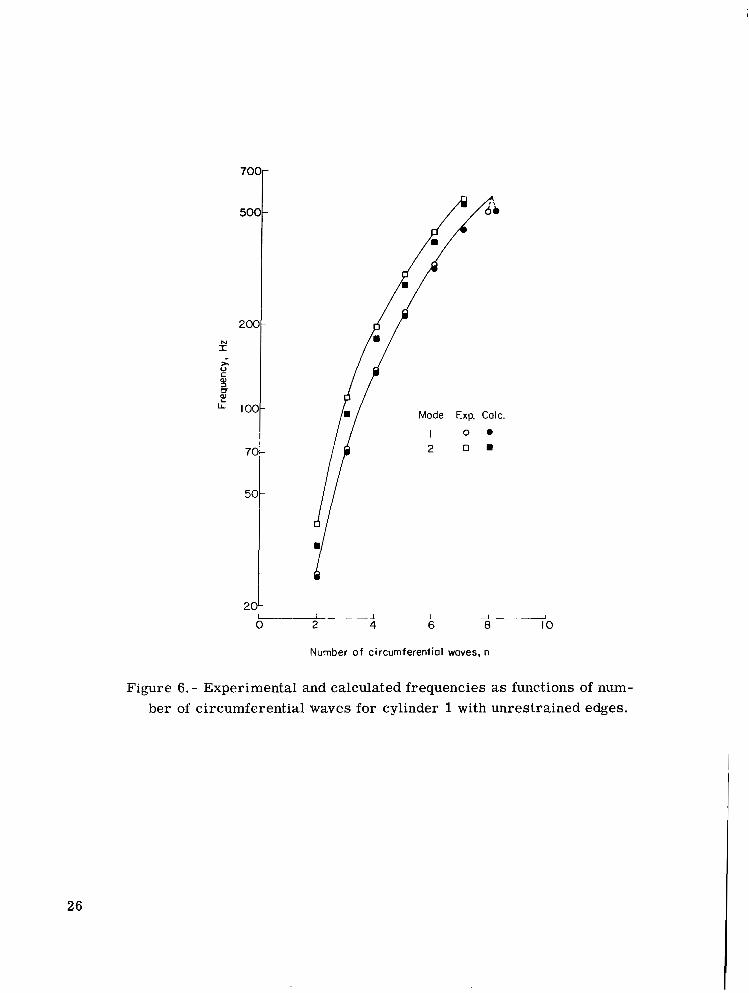
The results of this study are presented in figures 6 to 19. The modes and fre- quencies of the three cylinders with the various edge restraints are presented first. Fig- ures 6 to 10 show the comparisons of experiment and calculation in terms of frequency as a function of the number of circumferential waves n. Curves are faired through the data points to indicate trends, but no physical significance should be given to frequencies other than at integral values of n. Table 111 is a compilation of these frequencies. Fig- ures 11 to 15 show the comparisons of experiment and calculation in t e rms of normalized mode shapes. The radial component of amplitude is plotted along a generator of the cylinder and is normalized to the maximum radial amplitude. The distance along the cylinder is measured from the top of ring 1. Also shown in these figures are the fre- quencies and circumferential wave numbers. Figure 16 shows a comparison of the calcu- lated frequencies for the clamped-edge cylinder and the u-deflection-released cylinder in terms of the number of circumferential waves.
The effects of the ring properties are presented in figures 17 to 19. Figure 17 shows a comparison of experimental and calculated frequencies for various values of n for the end rings separated from the shells. Figure 18 shows the effect of varying the bending stiffness of the end rings in the calculations of frequency for several values of n and presents experimental frequencies for comparison. Figure 19 shows the effect of varying the bending stiffness on the predicted mode shapes.
Resonant frequencies determined by the Kennedy-Pancu method and damping factors obtained from the Kennedy-Pancu plots are presented in table IV.
Modes and Frequencies
Unrestrained-edge (free-edge) conditions. - The analysis gave good frequency results for the cylinders having free edges (see figs. 6, 7, and 8) over the range of modes investigated. Excellent agreement was obtained for the mode shapes of cylinders 2 and 3 in the range of n from 2 to 7 (see figs. 12 and 13). In general, the agreement between experimental and calculated mode shapes for cylinder 1 was good; however, for some of the modes, experimental data indicated a local bending at the end of this cylinder, where- as analysis did not predict this phenomenon (for example, see the mode at an experi- mental frequency value of 38.8 Hz in fig. 11). No explanation for this bending was
9

determined in the present study. Other deviations from the predicted mode shapes were observed, such as the wiggles at experimental values of 326.2 Hz in figure 11 and 159.6 Hz in figure 12; however, these wiggles were attributed to difficulties in the instrumentation and are not considered significant.
The radial components of amplitude along a generator for cylinders 2 and 3 (figs. 12 and 13) do not behave like those for cylinder 1 (fig. 11). For cylinder 1, the components of amplitude are all in phase at the lowest frequency mode for all values of n and they all have one nodal line near the center of the cylinder at the second lowest frequency mode for all values of n. These modes for cylinders 2 and 3 cannot be described in such a manner. For example, as shown in figure 12, the lowest frequency mode at n = 5 has a nodal line near one end of the cylinder. The lowest frequency mode for n = 6 has not only a nodal line near one end of the cylinder but considerable curva- ture at the opposite end. These complex mode shapes are attributed to complicated ring effects which make simple descriptions of the various mode shapes difficult.
Restrained-edge conditions. - " ~ - Representing the standard fasteners as clamped edges and the hinged joints as simply supported edges did not result in as high a degree of analytical-experimental correlation as was achieved for the free-edge condition. For cylinder 2 the measured frequencies differed from the calculated frequencies by as much as 12.5 percent for modes with values of n from 4 to 8 (figs. 9 and 10). For the modes with n = 2 and n = 3, the difference was much greater, reaching almost 100 percent at n = 2 for cylinder 2 with hinged joints (fig. 10). The predicted and measured normalized mode shapes for cylinder 2 were in excellent agreement for all values of n (figs. 14 and 15).
Analysis in&cated that there should be little difference (less than 1 percent) between the calculated frequencies for the clamped-edge cylinder and the simply supported cylin- der (compare calculated frequency values in figs. 14 and 15). For cylinder 2 with standard fasteners, asymmetries in the cylinder caused two similar modes to occur at n = 2 and at n = 3. Experimentally, the largest difference between the frequency when standard fasteners were used and when hinged joints were used was approximately 18 per- cent for the n = 2 mode. However, for the modes above n = 3, there is less than a 2.6-percent difference in experimental frequencies for the two conditions.
The analytical investigation into the clamped-edge condition indicated that a releasing of the restraint on u at the clamped edge caused little change in the radial components of amplitudes; however, the predicted frequencies at n = 2 and n = 3 reduce to approximately one-eighth and one-half of their original values, respectively, as shown in figure 16. Since using just this variation of parameters caused the predicted
10

frequencies to bound the experimental frequencies by wide margins, far more under- standing of these types of boundary restraint is needed to obtain a good mathematical representation.
Effects of Ring Properties
Properties of rings 1 and 4-.- A study of rings 1 and 4 (with clips) was conducted to investigate the accuracy of their representation in the mathematical model. The natural frequencies of these rings were calculated by using the same mass and stiffness matrices that are used as input in the ring-stiffened-shell program. These frequencies are compared with experimentally obtained frequencies of the rings in both the in-plane direction and the out-of-plane direction, and a plot of frequency as a function of the num- ber of circumferential waves is shown for rings 1 and 4 in figures 17(a) and 17(b), respectively. The in-plane modes for both rings show correlations of better than 5 per- cent, while the calculated frequencies in the out-of-plane direction are, at best, approxi- mately 60 percent of the experimental frequencies. The differences between calculated and experimental out-of-plane frequencies were attributed to the inadequacies of the assumption that the clips add only mass.
Effect on cylinder response.- Although the out-of-plane frequencies of rings 1 and 4 were not accurately predicted from the mathematical model, there was good experimental-analytical correlation between both the mode shapes and frequencies for all the cylinders with free edges. This agreement indicates that the out-of-plane stiffnesses of rings 1 and 4 do not have much effect on the response of these cylinders. In addition, ring 5 in cylinder 3 is composed of two rings back to back and, as stated previously, the experimental-analytical correlations for this cylinder were excellent.
Further investigation into the effects of the end rings on the response of the cylinders was conducted analytically by varying the parameter E11 of rings 1 and 4. Shown in figure 18 is a comparison of the frequencies predicted by using three bendmg- stiffness conditions: (1) E11 calculated from the structure, (2) increasing E11 50 percent for rings 1 and 4, and (3) increasing E11 50 percent for ring 4 and decreasing E11 50 percent for ring 1.
A band covering *11 percent of a mean value would encompass all three conditions for the lowest mode for any value of n; bands covering *6 percent and k7 percent would suffice for the second lowest mode and third lowest mode, respectively. These bound- aries completely enclose all frequencies obtained, and if just the condition of EI1 being increased by 50 percent for both rings were considered, the percentage deviation would be less than k5 percent. It may also be noted that the curves all follow the same general
11
I

trend. Thus, in order to obtain good predictions of the resonant frequencies in the pres- ent investigation, it is not necessary to know very accurately the bending stiffness in either the in-plane or out-of-plane direction of the end rings.
While the parameter E11 does not have a major effect on the resonant frequencies of the free-edge cylinders, it does affect the mode shapes. Previously, it was shown that excellent experimental-analytical agreement was obtained for the mode shapes up to values of n = 7. With variations on EI, significant differences can be observed; for example, in figure 19(a) the lowest frequency mode that exhibits a node line occurs at n = 3 for the case of decreasing E11 of ring 1 and increasing E11 of ring 4, a t n = 5 for the calcu- lated EI1, and at n = 6 for the case of increasing E11 of rings 1 and 4. Other gross discrepancies can be observed in the mode shapes, with the worst being for the second lowest mode at n = 7 (fig. 19(b)).
Structural Damping
Str-xtural damping factors, equal to twice the ratio of structural damping to critical damping for an equivalent viscous damped system (see eq. (l)), and resonant frequencies determined from the Kennedy-Pancu plots for cylinder 2 supported on strings are pre- sented in table IV. The resonant frequencies determined from the complex plane plots concurred with those determined by selecting peak amplitudes which had a phase angle between input force and acceleration of close to 90°. In addition, the complex plane plots indicated there was little off-resonant contribution to the various modes. The maximum difference between resonant frequencies obtained by the two methods was only 2.3 percent, which occurred for the fourth lowest frequency mode at n = 5.
Damping factors p ranged from 0.016 for the second lowest frequency mode at n = 2 to 0.004 for both the second lowest frequency mode at n = 5 and the third lowest frequency mode at n = 6. With damping values this low, the differences in the predicted shapes and the resonant frequencies with and without damping would be negligible. Com- parison of these damping values with equivalent damping values computed from experi- mental logarithmic decrements reported in reference 5 shows the damping to be slightly lower for the present cylinders, but not significantly so when considering the accuracy of damping measurements.
CONCLUDING REMARKS
An experimental and analytical investigation of the dynamic response character- ist ics of axisymmetric-ring-stiffened bonded-aluminum honeycomb cylinders has been
12

conducted. Calculated natural frequencies and mode shapes were compared with experi- mental resonant frequencies and normalized resonant response shapes in order to evalu- ate a finite-element analytical representation of the cylinders. Three configurations having length-diameter ratios of 0.25, 0.92, and 1.16 were investigated with free edges. In addition, the cylinder with a length-diameter ratio of 0.92 was studied with two types of edge restraints.
It was determined that both mode shapes and resonant frequencies can be adequately predicted for cylinders having free edges. Rings produced complicated mode shapes; however, the analysis predicted these mode shapes with excellent agreement for the cylinders having length-diameter ratios of 0.92 and 1.16. Some discrepancy in the mode shapes was observed at the end of the cylinder with a length-diameter ratio of 0.25, where the analysis did not predict a sharp change in curvature as was observed experimentally in some of the modes.
The agreement between predicted and experimental frequencies for the restrained- edge conditions was poor for the lower values of circumferential wave number n (values of 2, 3, and 4) but was better for the higher values of n. An analytical investigation into the representation of the edge restraint showed a significant sensitivity of the predicted frequencies to this parameter (variations of almost 100 percent for the lower values of n)
1 The predicted and measured mode shapes were in excellent agreement for all values of n and were not significantly affected by the edge restraint.
In this study, it was determined that an accurate representation of neither the in- plane nor out-of-plane stiffness of the end rings was necessary to obtain good frequency predictions for the cylinders. In addition, good mode-shape agreement between calcula- tions and experiment for the cylinders was obtained when using a poor representation of the out-of-plane stiffness of the end rings. However, significant differences were observed in the calculated and experimental mode shape of a cylinder when the in-plane stiffness of the end rings was varied in the analysis. The damping values of these honey- comb cylinders are in the range of those for other reported honeycomb structures.
Langley Research Center, National Aeronautics and Space Administration,
Hampton, Va., October 1, 1970.
13

REFERENCES
1. Bert, Charles W.; Egle, Davis M.: Dynamics of Composite, Sandwich, and Stiffened Shell-Type Structures. J. Spacecraft Rockets, vol. 6, no. 12, Dec. 1969, pp. 1345-1361.
2. Yu, Yi-Yuan: Vibrations of Elastic Sandwich Cylindrical Shells. Trans. ASME, Ser. E: J. Appl. Mech., vol. 27, no. 4, Dec. 1960, pp. 653-662.
3. Powell, Clemans A., Jr.; and Stephens, David G.: Vibrational Characteristics of Sand- wich Panels in a Reduced-Pressure Environment. NASA TN D-3549, 1966.
4. Clary, Robert R.; and Leadbetter, Sumner A.: An Analytical and Experimental Investi- gation of the. Natural Frequencies of Uniform Rectangular-Cross-Section Free-Free Sandwich Beams. NASA TN D-1967, 1963.
5. Bert, C. W.; Wilkins, D. J., Jr.; and Crisman, W. C.: Damping in Sandwich Beams With Shear-Flexible Cores. Trans, ASME, Ser. B: J. Eng. Ind., vol. 89, no. 4, NOV. 1967, pp. 662-670.
6. Steeves, Earl C.; Durling, Barbara J.; and Walton, William C., Jr.: A Method for Computing the Response of a General Axisymmetric Shell With an Attached Asym- metric Structure. AIAA Structural Dynamics and Aeroelasticity Specialist Con- ference and the ASME/AIAA 10th Structures, Structural Dynamics, and Materials 6
Conference, Apr. 1969, pp. 302-328.
7. Adelman, Howard M.; Catherines, Donnell S.; and Walton, William C., Jr.: A Method for Computation of Vibration Modes and Frequencies of Orthotropic Thin Shells of Revolution Having General Meridional Curvature. NASA T N D-4972, 1969.
8. Adelman, Howard M.; Catherines, Donnell S.; Steeves, Earl C.; and Walton, William C., Jr.: User's Manual for a Digital Computer Program for Computing the Vibration Characteristics of Ring-Stiffened Orthotropic Shells of Revolution. NASA TM X-2138, 1970.
9. Naumann, Eugene C.; and Flagge, Bruce: A Noncontacting Displacement Measuring Technique and Its Application to Current Vibration Testing. Preprint No. 16.18-5-66, Instrum. SOC. Amer., Oct. 1966.
10. Mead, D. J.: The Internal Damping Due to Structural Joints and Techniques for General Damping Measurement. C.P. No. 452, Brit. A.R.C., 1959.
11. Kennedy, Charles C.; and Pancu, C. D. P.: Use of Vectors in Vibration Measurement and Analysis. J. Aeron. Sci., vol. 14, no. 11, Nov. 1947, pp. 603-625.
12. Schoenster, James A.; and Clary, Robert R.: Experimental Investigation of the Longi- tudmal Vibration of a Representative Launch Vehicle With Simulated Propellants. NASA TN D-4502, 1968.
14

TABLE I. - MODEL DESCRIPTION
(a) Properties of cylinders 1, 2, and 3
Property
1, cm . . . d, cm . . .
1 l/d . . . .
Cylinder 1
16.22 66.04 0.25
60.45 76.67 66.04 66.04
(b) Properties of shells for cylinders 1, 2, and 3
[ Property I Cylinder 1 I Cylinder 2
M, kg/m2 . . . 0.6623 0.7329
hc, cm . . . . 0.15367 0.15367 hf, c m . . . . .
6.22 €7, cm . . . . 7.60 €6, cm . . . .
10.19 3.28 e 5 , cm . . . . 10.16 2.54 e 4 , cm . . . . 10.92 2.54 €3, cm . . . . 6.35 2.54 €2 , cm . . . . 6.22 2.54 €1, cm . . . . 0.33 0.33 v . . . . . . .
0.00508 0.00508
(c) Properties of rings
Property I Ring 1 1 Ring 2 1 Ring 3
il, cm . . . . . 0.0594 0 -0.0393 i.3, cm . . . . .
0 0 *0.820
@, deg . . . . . . 90 90 90
EI1, N-m2 . . . 4.355
32.802 32.861 32.900 a, cm . . . . . . 3.073 3.049 0.08943 GJ, N-m2 . . . . 3.242 2.864 1.297 EA, MN . . . . .
0 0 -2.695 EI13, N-m2 . . . 4.813 4.811 29.90 EI3, N-m2 . . . 9.110 0.3007
m i , kg/m . . . . 0.1263 0.1116 0.06978 m2, mg-cm . . .
3.550 0.1172 2.342 m3, mg-cm . . . 1.876 1.875 16.07
~~
Cylinder 3
0.6623 0.7329
0.15367 0.00508
0.33 12.57 10.92 10.16 10.19 15.21 14.83
~
Ring 4
-0.818
0.00137
90 2.791 24.58
-0.2797 1.229
0.08443 32.847
0.06753 13.51 1.533
Ring 5
0
0.00137 90
5.581 213.9
0
2.458 0.1689 32.847 0.1350
117.5 3.066
*Except for cylinder 3 at juncture 7, where E l = -0.820.
15

Section
TABLE 11.- SUMMARY OF CONDITIONS USED FOR
EXPERIMENTAL-ANALYTICAL COMPARISONS
Cylinder 1 Cylinder 2 Cylinder 3 Ring 1 (with clips) Ring 4 (with clips)
~~
Unrestrained (Free edge)
J J J J J
~ ."
Edge restraints
Standard fasteners (Clamped edge)
J
Hinged joint (Simply supported edge)
J
16
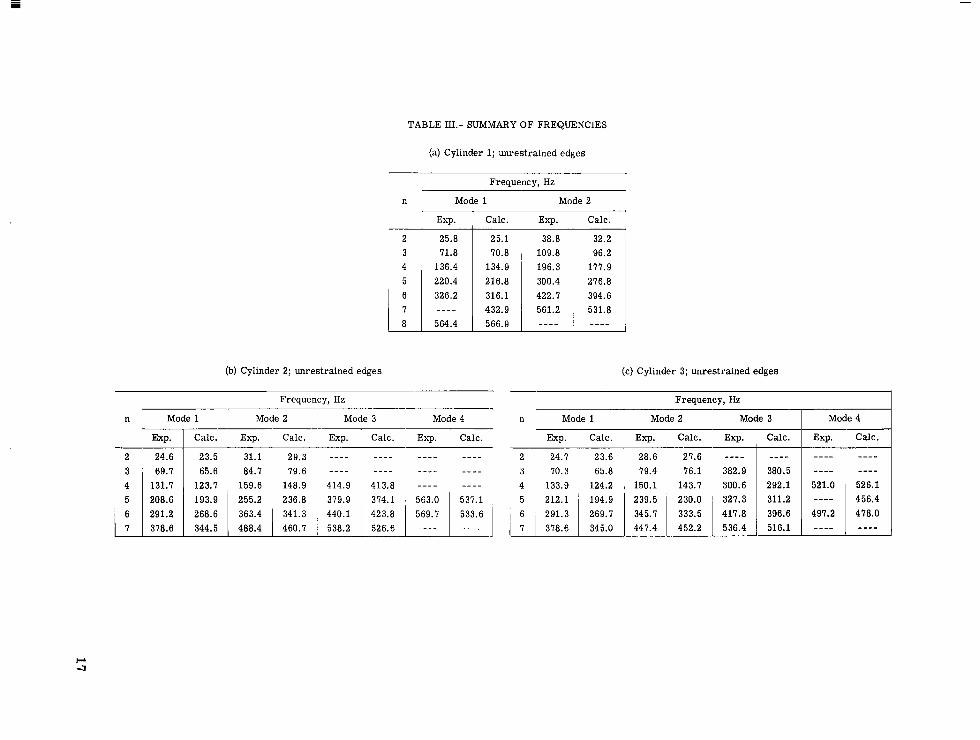
TABLE W.- SUMMARY OF FREQUENCIES
(a) Cylinder 1; unrestrained edges
Frequency, Hz
n Mode 1 Mode 2
Exp. Calc. Exp. Calc.
2 25.8 3 71.8
564.4
25.1 70.8
134.9 216.8 316.1 432.9 566.9
38.8 109.8 196.3 300.4 422.7 561.2 ""
32.2 96.2
177.9 276.8 394.6 531.8 "" 1 1
(b) Cylinder 2; unrestrained edges (c) Cylinder 3; unrestrained edges
7 - I Frequency, Hz Frequency, Hz
n Mode 1 Mode 2 Mode 3 n Mode 1 Mode 2 Mode 3 Mode 4 Mode 4
Exp. Calc. "
""
-~ ~~~
Calc. Exp. Calc. Exp. Calc. Exp. Calc. "
""
I L Exp. Calc. Exp. Calc. Exp. _ _ _ ~ ~ ~
""
382.9 300.6
417.8
Calc.
""
380.5 292.1 311.2 396.6 516.1
Exp.
2 24.6 " c
27.6 76.1
143.7 230.0 333.5 452.2
31.1 29.3 84.7 79.6
159.6 148.9 255.2 236.8
28.6 79.4
150.1 239.5 345.7 447.4
23.5 65.6
123.7 193.9 268.6 344.5
2 24.7 3 70.3 4 133.9 5 212.1
23.6 65.8
124.2
269.7 345.0
""
""
521.0 ""
497.2 ""
""
""
414.9 379.9 440.1 538.2
"" ""
"" ""
413.8 - - - -
i I L
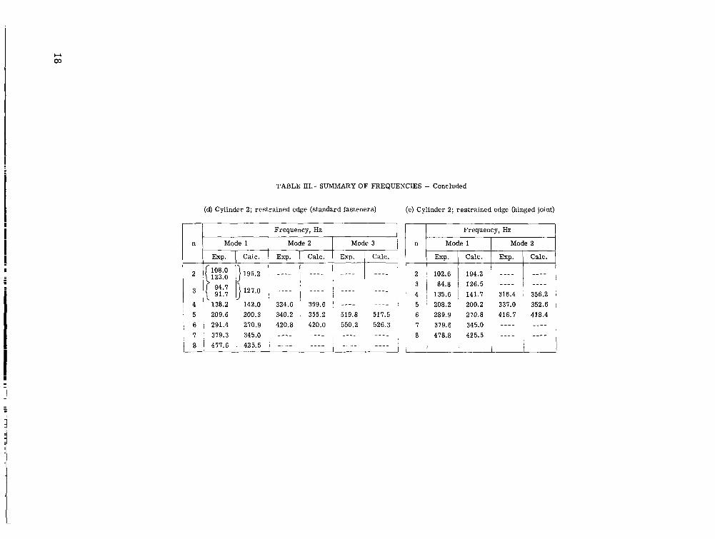
TABLE IIL- SUMMARY OF FREQUENCIES - Concluded
(d) Cylinder 2; restrained edge (standard fasteners) (e) Cylinder 2; restrained edge (hinged joint)
~
Frequency, Hz
Mode 1 Mode 2 Mode 3
Exp. Calc. Exp. Calc. Exp. Calc.
""
3 !( :::; ) 127.0 , - - - -
4 j 138.2 142.0 ' 324.6 359.6
'
---- "" ,
' 5 209.6 200.3 340.2 , 355.2 519.8 517.5 I 6 ; 291.4 270.9 420.8 420.0 , 550.2 526.3
345.0 ---- "" , "" ""
i 425.5 1 _ -__ , _ _ _ _ 1 _ _ _ _ _ _ _ _ ~ I
i n i
I Frequency, Hz I Mode 1
Calc. Exp. Calc. Exp.
Mode 2
102.6 126.5 ---- I "" 84.8
"" 194.2 ---- !
1 135.6 1 141.7 316.4 , 356.2 1 1 208.2 200.2 337.0 352.6 I
289.9 270.8 416.7 418.4 379.6 345.0 ---- ""
478.8 425.5 ---- ""
I
-!

TABLE IV.- RESONANT FREQUENCIES AND DAMPING FACTORS
OBTAINED FROM KENNEDY-PANCU PLOTS FOR
CYLINDER 2 WITH STRING SUPPORT
1 I Mode 1 I
I Mode 2 Mode 4 Mode 3
Frequency, Hz factor p Hz
Frequency, Damping
2
482.9 .005 377.8 7 360.3 .007 289.7 6 253.0 .006 207.1 5 157.9 .015 131.0 4 83.7 .008 69.1 3 30.9 0.008 24.6
Damping factor p Hz factor p Hz factor p
' Damping Frequency, Damping Frequency,
0.016 "" "" "" ""
.005
.005
"" "" .005 536.7 .005 .005 567.5 ,004 437.6 .005
0.007 550.6 ,005 379.8 .004
"" "" 0.007 410.6
"" "" "" ""

L-70-3321.1 (a) Cylinder 1. (b) Cylinder 2.
Figure 1.- The honeycomb cylinders.
‘f ’.

Electromagnetic
.. , I '' 1 \ * - Ayelerometer
r I
shaker I
(c) Cylinder 3.
Figure 1. - Concluded.
L-70-3322.1
21

7-
1 1.270 crn
# .719 crn I
I I 60.45 crn
t I .270 cm 1.397 c m t
,704 cm .592 crn
R i m 4 Ring 3
Figure 2.- Schematic drawing of cylinder 2.
22

Displacement probe -
. -
4 Test cylinder
Force Conditioning equipment
I
l i t I l\- Accelerometer - I Conditioning I I 1-
Tracking
Conditioning equipment
Relative omplitude
(dc onolog)
Position Indicator x plotter on trolley
oscillator
Frequency (dc onolog)
1 Analog I Analog
acceleration signol signal
force
component
In-phose Quadrature component component
1-
Figure 3.- Schematic view of instrumentation.
23

362 "1 I'
t Out of phose I n phase 4 Components referenced to force
Figure 4. - Kennedy-Pancu plot of acceleration at the input-force location. Cylinder 2 with unrestrained edges; second lowest mode (mode 2) at n = 6.
24

* diom 66.04 cm,
I . I I i Ring 2
66.04 cm - diom
U
I
12.57
I 31.32
15.16
14.83
cm
-
cm
-
cm
I Ring I
(a) Cylinder 1. (b) Cylinder 2. (c) Cylinder 3.
Figure 5.- Analytical representation of the shells and ring attachments.
25
Mode Exp. Colc.
I 0 .
2 0 .
I "1 2
Number of circumferential waves, n
- 4 6 8 I O
Figure 6.- Experimental and calculated frequencies as functions of num- ber of circumferential waves for cylinder 1 with unrestrained edges.
26

Mode Exp. Colc.
I O . 2 0 .
3 o * 4 A A
I 2 A 6 I I
8 I O
Number of circumferential waves, n
Figure 7.- Experimental and calculated frequencies as functions of num- ber of circumferential waves for cylinder 2 with unrestrained edges.
27

1 rl 20L -
0 2
2 3 4
I 4 ~ 6
Exp. Colc.
0 . 0 . o + A A
I
8 10 1
Number of circurnferentiol woves, n
Figure 8.- Experimental and calculated frequencies as functions of num- ber of circumferential waves for cylinder 3 with unrestrained edges.
28

0
I O 0 ; \ i 70 L 0 L" . .1 . ~
2 i
Mode
I 2 3
6 - 1 I 8 IO
Number o f c i rcurn feren t io l woves, n
Figure 9.- Experimental and calculated frequencies as functions of num- ber of circumferential waves for cylinder 2 with standard fasteners.
29

a
a
Number of circurnferentiol waves, n
Figure 10. - Experimental and calculated frequencies as functions of number of circumferential waves for cylinder 2 with hinged joints.
30

I
. ""L " """_
"
I .Or
I.Oy
d 4 ' I I 8 12 16
Distance along cylinder, cm
Frequency, Hz
Exp.- - C d C .
25.8
38.8
71.8
109.8
136.4
25. I
32.2
70.8
96.2
134.9
Figure 11.- Experimental resonant response shapes and cal- culated mode shapes for cylinder l with unrestrained edges.
31

n Frequency, Hz
- E X ~ . - " C O ~ C .
4 196.3 177.9
0 5 220.4 216.8
0 6 326.2 316.1
6 422.7 394.6
Distance along cylinder, cm
Figure 11.- Continued.
32

I
n Frequency, Hz -ExP. --
I T "-- Calc
" -" " -- 1
0 I 7 - 432.9
7 56 1.2 531.8
'4 7 , -J " --" " 0 I I 8 564.4 566.9
0 4 8 12 16
Distance along cylinder, cm
Figure 11.- Concluded.
33

n Frequency, Hz
$ 1 2 -1.0 +
2
3
3
4
4
31. I
69.7
84.7
I3 1.7
159.6
29.3
65.6
79.6
123.7
148.9
Distance along cylinder, cm
Figure 12.- Experimental resonant response shapes and cal- culated mode shapes for cylinder 2 with unrestrained edges.
34

n Frequency, Hz -Exp.- - Colc.
k Y
Oi ”------ 5 208.6 193.9
- 7 378.6 344.5
L
0 I I I
20 ~~~
40 60
Distance along cylinder, cm
Figure 12. - Continued.
35
I

n Frequency, Hz -Exp.- - C O ~ C .
379.9
41 4.9
374. I
41 3.8
6 440.1 423.8
6
- 1.01 0 I I " - "" .. J
20 40 60
Distance along cylinder, cm
488.4
538.2
563.0
569.7
460.7
5 26.6
537. I
533.6
Figure 12. - Concluded.
36

n Frequency, Hz “ E x p . - - Calc.
””” 2 24.7 23.6
I .Or
0 ”-”“-” 3 70.3 65.8
- 1.0 I I 0
I
IO 1
20 1 30
I
40 I
50 I
60 u 70 80
Distance along cylinder, cm
Figure 13. - Experimental resonant response shapes and calculated mode shapes for cylinder 3 with unrestrained edges. (The dis- tance along the cylinder is measured from the top of the ring 1 that is attached at juncture 1.)
37

Frequency, Hz
Exp. --Calc.
212.1 194.9 - ~~-
- I.0L
-I .o i 0 IO 20 30 40 50 60 70 80
1 L - L___L ""
Distance along cylinder, cm
Figure 13.- Continued.
38

I I I I I I I 0 10 20 30 40 50
u 60 70 80
Distance along cylinder, cm
Figure 13.- Concluded.
39
I

n Frequency, Hz
40
2 108.0 195.2 123.1
I .o- 0) -0 3 c 0-
4 138.2 142.0 .- - a 5 U er .- -
1.0 _"" b
- z 0 5 209.6 200.3
4 324.6 359.6
Distance along cylinder, cm
Figure 14.- Experimental resonant response shapes and calculated mode shapes for cylinder 2 with standard fasteners (clamped edges).
.. . .. . _. .. -. .. .. ... .... .. .

n Frequency, Hz
'g OI
5 519.8 517.5
- I.O\ I I J
0 20 40 60
Distance along cylinder, cm
Figure 14. - Concluded.
41

n Frequency, Hz
2 102.6 I 94.2
I .Or
I - 1 0 20 40 60
- 1
Distance along cylinder, c m
Figure 15.- Experimental resonant response shapes and calculated mode shapes for cylinder 2 with hinged joints (simply supported edges).
42

I. n Frequency, Hz " E x p . --CO~C.
337.0 352.6 /
-1.0
I . 1 7 379.6 345.0
- I .oL I I I I 0 20 40 60
Distance along cylinder, cm
Figure 15.- Concluded.
43

700-
500-
? Clamped u deflection Mode
/ l I I
I
f released e 0 I
0 2 0 3
~ ""_
i) I I I I I I I
I 0
1 I 2 4 k A I
I O
Number of Circumferential waves, n
Figure 16.- Comparison of calculated frequencies as functions of number of circumferential waves for cylinder 2 with a clamped edge and cylinder 2 with the u deflection released.
44

60(
20(
I O( N I
0 ZI
al CT
LL
c 6C
E
2c
I C
6
P
Exp. Calc
-c- -f- In p lane
-0- -.- Out of p l a n e
I I i
I 2 4 I - I
6 a I IO
Number o f c i r c u m f e r e n t i a l waves , n
(a) Ring 1.
Figure 17.- Experimental and calculated frequencies as functions of number of circumferential waves n for rings 1 and 4 with clips.
I

200-
I" loo- )I 0 C a,
60-
2 a,
20- I
Colc.
"o-- In plane
-m- Out of plane
I I 8 I O
Number of circumferential waves, n
(b) Ring 4.
Figure 17.- Concluded.
46

Number o f circumferential waves, n
(a) Lowest frequency mode for any value of n.
Figure 18.- Comparison of experimental resonant frequencies with natural frequencies calculated by using modified values of EI1. Cylinder 2 with unrestrained edges.
47

6oor
20 ! (!" 2 4 I tk A I10 Number of circumferential waves, n
(b) Second lowest frequency mode for any value n.
Data boundaries f 7%
30d 6 I 1- J 2 4 6 8 IO
Number of circumferential waves, n
(c) Third lowest frequency mode for any value n.
Figure 18. - Concluded.
48

Bending stiffness
Ring I Ring 4
- € 1 1 E I I "" 1.5 €11 1.5 E11 - " .5 E11 1.5 €11
Frequency, Hz Frequency, HZ
23.5 "" " "
-.5 I I I I I 1 I I 1 I I 1
268 6
-.5 1 1 1 J 1 1 I I I I
0 .2 .4 .6 .8 1.0 0 .2 .4 .6 .8 1.0 1 1
s / 1 S / l
(a) Lowest frequency modes.
Figure 19.- Calculated mode shapes for modified values of E11 for r ings 1 and 4. Cylinder 2 with unrestrained edges.
49

Bending stiffness
Ring I Ring 4
- E I I E11 "" 1.5 E11 1.5 E11 - " .5 E11 1.5 E11
I .o Frequency, Hz
n = 2 - I .o n.3
I I I L I J 1 1 1 111
341.3
- . s t /
- I .o L n=6
L 1 I 1 - 1 I 1 1 1 0 .2 .4 .6 .8 1.0 0 .2 .4 .6 .8 1.0
111
s/l 5/1
(b) Second lowest frequency modes.
Figure 19.- Continued.
50
" . ...

Bending stiffness
Ring I Ring 4
- E I I EII "" 1.5 €1, 1.5 E11 -" .5 €11 1.5 €11
I . O r Frequency, Hz Frequency, Hz
420.5 0 \ '
\ '\ y, 374.1 :'. -.5 413.8 '\
n = 4 \ . ...a
- 1.0 n=5
L
(c ) Third lowest frequency modes.
Figure 19.- Concluded.
51
I .

NATIONAL AERONAUTICS AND SPACE ADMINISTRAI ION
WASHINGTON, D. C. 20546
OFFICIAL BUSINESS FIRST CLASS MAIL
NATIONAL AERONAUTICS . POSTAGE A N D FEES PA11
SPACE ADMINISTRATIOb
06U 001 5 7 51 305 '71012 00903 A I R F O R C E W E A P O N S L A B O R A T O R Y / W L O L / K I R T L A N O A F B ? NEW PEXICO 87117
A T T E. L O U BOWMAN, CHIEFvrECH. L I B R A R Y
If Undeliverable (Secrion 1 Posral Manual) Do Nor Re
"The aeronaatical and space activities of the United Stntes shall be conducted so as t o contribute . . . t o the expansion of human knowl- edge of phenomena in the atmosphere and space. The Administration shall provide for the widest practicable and appropriate dissemination of jnforvration concerning i t s actiqlities and the resalts thereof."
-NATIONAL AERONAUTICS AND SPACE ACT OF 1958
NASA SCIENTIFIC A N D TECHNICAL PUBLICATIONS
TECHNICAL REPORTS: Scientific and TECHNICAL TRANSLATIONS: Information technical information considered important, published in a foreign language considered complete, and a lasting contribution to existing to merit NASA distribution in English. knowledge.
TECHNICAL NOTES: Information less broad derived from or of value to NASA activities. in scope but nevertheless of importance as a Publications include conference proceedings,
SPECIAL PUBLICATIONS: Information
contribution to existing knowledge.
TECHNICAL MEMORANDUMS:
monographs, data compilations, handbooks, sourcebooks, and special bibliographies.
Information receiving limited distribution TECHNOLOGY UTILIZATION because of preliminary data, security classifica- PUBLICATIONS: Information on technology tion, or other reasons. used by NASA that may be of particular
CONTRACTOR REPORTS: Scientific and interest in commercial and other non-aerospace applications. Publications include Tech Briefs,
technical information generated under a NASA Technology utilization R~~~~~~ and contract or grant and considered an important contribution to existing knowledge.
Technology Surveys.
Details on the availability of these publications may be obtained from:
SCIENTIFIC AND TECHNICAL INFORMATION OFFICE
NATIONAL AERONAUTICS AND SPACE ADMINISTRATION Washington, D.C. PO546