calibration and verification of detailed … · but the physical response of the hybrid iii is...
TRANSCRIPT

2017 NDIA GROUND VEHICLE SYSTEMS ENGINEERING AND TECHNOLOGY
SYMPOSIUM MODELING & SIMULATION, TESTING AND VALIDATION (MSTV) TECHNICAL SESSION
AUGUST 8-10, 2017 - NOVI, MICHIGAN
CALIBRATION AND VERIFICATION OF DETAILED HYBRID III 50TH PERCENTILE MALE ANTHROPOMORPHIC TEST DEVICE (ATD) BASED ON
EXTENSIVE MINE BLAST TESTS
Morten Rikard Jensen, PhD. CertaSIM, LLC
Castro Valley, CA
Mike Honaker General Dynamics Land Systems
Sterling Heights, MI
Alex Boglaev General Dynamics Land Systems
Sterling Heights, MI
ABSTRACT The work presented here comprises preliminary results for calibrating the
IMPETUS Afea Hybrid III 50th
percentile Male ATD for a blast scenario. The
calibration of the ATD model based upon the requirements defined for frontal
crash impact are presented followed by a discussion of the blast survivability tests
that were performed at General Dynamics Edgefield Test Center in South
Carolina. The model setup for the calibration based upon the blast tests are
presented which includes a discussion of the seating and blast models.
Preliminary numerical results for Lumbar and Lower Tibia forces are compared
with the experimental results. The correlation was good and calibration of the
remaining critical parameters continues.
INTRODUCTION Improvised Explosive Devices (IEDs) are a
major cause of warfighter injuries. The battlefield
is a dangerous environment and enhancements in
vehicle protection are critical. Studying the effect
of a mine blast on the vehicle structure is central
to improvements in vehicle designs. However, to
fully assess the effectiveness of a design it is
necessary to include the effect of the blast on the
warfighter and that is why an ATD
(Anthropomorphic Test Device) has to be included
in the design process.
ATDs are invaluable in the design of both
military and commercial vehicles. The first whole
body ATD, Sierra Sam, was built in 1949 for the
US Air Force [1]. Since then many other types
have been developed, the Hybrid II, SID, Tuff
Kelly, etc. [1] and in most cases the development
has been driven by the automotive industry to
improve the safety of commercial vehicles. The
Hybrid III ATD is an integral part of the design
process to assess automotive designs for safety.
The defense industry has also adopted the same
philosophy and so the Hybrid III ATD is currently
being used to assess survivability of the warfighter
for vehicle impact but also for the blast
environment. However, the loading that results
from a blast event is quite different than an
automobile frontal crash because the major
loading is characterized by large vertical forces.
But the physical response of the Hybrid III is
focused on automotive industry standards for

Proceedings of the 2017 Ground Vehicle Systems Engineering and Technology Symposium (GVSETS)
Calibration and Verification of Detailed Hybrid III 50th
Percentile Male Anthropomorphic Test Device (ATD) Based on
Extensive Mine Blast Tests, Jensen, et al.
Page 2 of 11
crashworthiness which means front and side
impact and the standards for calibrating a
numerical model of the Hybrid III ATD also
focuses on the same response parameters. This
makes it questionable to use them when applied to
mine blast scenarios [2] and the same problem
also occurs when applying a Hybrid III model to
drop tower tests [3]. The WIAMan (Warrior Injury
Assessment Manikin) project [4] was initiated
several years ago to better quantify injury
associated with mine blast events and it is
currently still in development and not ready for
widespread use. In the meantime the Hybrid III is
still the workhorse for the underbody blast design
and testing of military vehicles.
The work presented here highlights a detailed
model of the Hybrid III 50th
percentile Male ATD
that was developed for the IMPETUS Afea
Solver®, an Explicit Non-linear Transient Finite
Element Code. The geometry of the ATD model is
based upon the standards published by the
NHTSA (National Highway Traffic Safety
Administration). The ATD is calibrated to the
standard requirements specified in [5] and [6]. To
calibrate an ATD for blast events requires blast
test data. Blast survivability tests using
instrumented ATDs were performed at the General
Dynamics Edgefield Test Center in South
Carolina. A Hybrid III 50th
percentile physical
ATD was used in the tests. The ATD was placed
in a seated position in a rig and buried charges
were detonated in a very controlled and repeatable
manner under the rig in order to collect the
necessary injury data. The tests were performed in
July 2016. The test data can now be used to
calibrate the ATD, focusing on response
parameters such as Pelvic Acceleration, Lumbar
Force, etc. This paper provides a short
introduction to the ATD, shows the results of a
few selected configurations as verification of the
calibrated ATD for the automotive industry.
Furthermore, the mine blast experiments are
presented along with preliminary simulation
results for the lumbar and lower tibia forces.
THE ATD MODEL The ATD project was initiated in 2012 by
IMPETUS Afea AS and the Norwegian Defense
Research Establishment (FFI) with the goal of
developing a virtual ATD to capture the impulse
and deformations that occur during a blast event.
The Hybrid III 50th
percentile male ATD was
chosen since it represents the average size of a
warfighter and is often used in live-fire blast
testing of combat vehicles. The SAE standards
provide a basis for calibrating the ATD Model.
The ATD is equipped with the standard leg
components used in the automotive industry and is
show in Figure 1.
Figure 1: The ATD is based on the geometry of the Hybrid
III 50th
percentile Male ATD.
The first step in the project was to create the
finite element model based on the documentation
in [7]. The meshing took several iterations and a
mix of elements of different orders was applied to
fully utilize the benefits of the IMPETUS element
technology. The model takes advantage of
accurate high order elements (quadratic and cubic)
where accuracy is needed and linear elements in
those sections that are appropriate to maximize
computational efficiency. This includes both
hexahedron and tetrahedron elements. Figure 2
shows a mix of the different element types used in
various portions of the ATD.

Proceedings of the 2017 Ground Vehicle Systems Engineering and Technology Symposium (GVSETS)
Calibration and Verification of Detailed Hybrid III 50th
Percentile Male Anthropomorphic Test Device (ATD) Based on
Extensive Mine Blast Tests, Jensen, et al.
Page 3 of 11
Figure 2: The ATD makes use of a mixture of linear and
higher order elements.
An ATD model is in itself rather complex, but
the complexity increases significantly when
implementing it within a full vehicle model.
Therefore, it is of vital importance to have a good
file structure and dataflow. One needs to be able to
identify parts quickly in large models. To ensure
this, the model is organized in seven different
assemblies, where each represents a certain clearly
identifiable region of the ATD. The seven
assemblies are:
Head
Arms
Legs
Feet
Upper Torso
Lower Torso
Neck
The assemblies are shown individually in Figure
3. Each of the assemblies is presented in detail in
[8] where the data flow, files and positioning are
clearly described.
Figure 3: The ATD makes use of seven different assemblies.
The positioning of the parts (i.e., angles of the limbs) is
based upon the blast test set-up.
VERIFICATION FOR FRONTAL CRASH The Hybrid III 50
th Percentile ATD was
developed for automotive crash testing and with
that comes calibration tests specified for the
automotive industry. The first step to certify the
Hybrid III 50th
Percentile Blast dummy involves
satisfying those requirements. The tests used for
the calibration of the ATD follow the guidelines in
[5] or [6] depending upon the set-up as defined for
each test. The calibration work was performed by
IMPETUS Afea AB and FFI. In the later stages,
CertaSIM, LLC was also involved. In total nine
different calibration tests where successfully
completed, leading to an accurate ATD that can be
used for crash test simulations. The tests, well
known in the automotive industry, are as follows:
Head Drop Test
Neck Flexion Test
Neck Extension Test
Thorax Impact Test
Knee Impact Test
Knee Slider Test
Upper Foot Impact Test
Lower Foot Impact Test
Static Foot Impact Test

Proceedings of the 2017 Ground Vehicle Systems Engineering and Technology Symposium (GVSETS)
Calibration and Verification of Detailed Hybrid III 50th
Percentile Male Anthropomorphic Test Device (ATD) Based on
Extensive Mine Blast Tests, Jensen, et al.
Page 4 of 11
Verification and documentation of all the above
calibration tests have been performed and
described in [8]. In the following sections, the
Neck Flexion, the Knee Impact Test and the Foot
Test from the verification work are briefly
described and the results shown.
Neck Flexion Test The Neck Flexion Test consists of the Neck and
Head assembly mounted on a pendulum which
includes the brackets. The test results for the neck
initially bending forward then backwards are show
in Figure 4.
Figure 4: Finite Element set-up for the Neck Flexion Test.
The Hybrid III User’s Manual J2856 [5] is the
standard on which this calibration is based. A
pendulum is released to allow a free fall from a
given height that makes it achieve a velocity
between 6.89 m/s and 7.13 m/s. The pendulum is
deaccelerated according to values in the standard.
In the numerical simulation the pendulum is not
modeled but the Pad Sternum is used. A
prescribed velocity is defined to represent the
motion in the experimental set-up. The Pad
Sternum is located in the lower Torso assembly
which is the only part added besides the Neck and
Head assemblies.
The performance specifications are given in [5],
covering rotation and moments. Rotation is
referenced to a horizontal plane passing through
the base of the skull. Maximum rotation of the D-
plane should be 64° to 78° with respect to the
pendulum and must occur between 57 and
64 msec after impact. Furthermore, the head
rotation versus time curve must cross the zero
angle between 113 and 128 msec. Figure 5 shows
that the modeled results are within the
requirements.
Figure 5: Numerical results for Neck Flexion compared
with J2856 [5] maximum rotation and zero crossing,
showing agreement with the requirements.
IMPETUS Modeled Pendulum Response
J2856 Window for Maximum Moment
J2856 Window for Zero Crossing
Figure 6: Numerical results for the Neck Flexion Test
compared with the specification in J2856 [5] showing the
model is in agreement with the moment requirements.
There are more requirements for the computed
moments where the maximum moment of the head
around the global Y-axis must be between 88.1 N-
m and 108.4 N-m occurring between 47 and 58
msec. Also, the decaying part of the moment
versus time curve must cross the zero axis
between 97 and 107 msec. Figure 6 shows that the
numerical results are within the requirements,
Proceedings of the 2017 Ground Vehicle Systems Engineering and Technology Symposium (GVSETS)
Calibration and Verification of Detailed Hybrid III 50th
Percentile Male Anthropomorphic Test Device (ATD) Based on
Extensive Mine Blast Tests, Jensen, et al.
Page 5 of 11
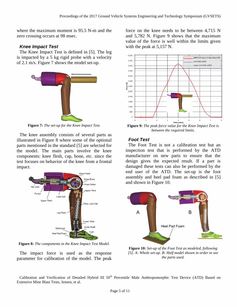
where the maximum moment is 95.5 N-m and the
zero crossing occurs at 98 msec.
Knee Impact Test The Knee Impact Test is defined in [5]. The leg
is impacted by a 5 kg rigid probe with a velocity
of 2.1 m/s. Figure 7 shows the model set-up.
Figure 7: The set-up for the Knee Impact Test.
The knee assembly consists of several parts as
illustrated in Figure 8 where some of the optional
parts mentioned in the standard [5] are selected for
the model. The main parts involve the knee
components: knee flesh, cap, bone, etc. since the
test focuses on behavior of the knee from a frontal
impact.
Figure 8: The components in the Knee Impact Test Model.
The impact force is used as the response
parameter for calibration of the model. The peak
force on the knee needs to be between 4,715 N
and 5,782 N. Figure 9 shows that the maximum
value of the force is well within the limits given
with the peak at 5,157 N.
Figure 9: The peak force value for the Knee Impact Test is
between the required limits.
Foot Test The Foot Test is not a calibration test but an
inspection test that is performed by the ATD
manufacturer on new parts to ensure that the
design gives the expected result. If a part is
damaged these tests can also be performed by the
end user of the ATD. The set-up is the foot
assembly and heel pad foam as described in [5]
and shown in Figure 10.
Figure 10: Set-up of the Foot Test as modeled, following
[5]. A: Whole set-up. B: Half model shown in order to see
the parts used.

Proceedings of the 2017 Ground Vehicle Systems Engineering and Technology Symposium (GVSETS)
Calibration and Verification of Detailed Hybrid III 50th
Percentile Male Anthropomorphic Test Device (ATD) Based on
Extensive Mine Blast Tests, Jensen, et al.
Page 6 of 11
This is a static compression test since the loading
is 15 mm/min according to the standard. The force
deflection curve has to be within a specified
corridor. The curve is to be offset so that zero
displacement is at a force of 1 lbf (4.5 N). In the
numerical model this curve is found by cross
plotting the force and displacement for the ground
in the global Z-direction. The numerical result is
plotted together with the corridor in Figure 11
showing the response is well within the required
limits.
Figure 11: Numerical result within the limits required in [5].
MINE BLAST TESTS There is very little specific and useful
information about blast tests of an ATD that can
be found in the open literature. In general, relevant
information as charge size, blast impulse, etc. are
presented as normalized values. Furthermore, the
accuracy of the blast test is important because it is
used to validate numerical models. Blast event
experiments have to be under very controlled and
consistent procedures which require a very
professional and knowledgeable staff. Based on
these observations, CertaSIM, LLC chose the GD
Land Systems Edgefield Test Center located in
South Carolina to perform the tests. There were
three days of blast tests performed with a Hybrid
III 50th
Percentile ATD. A series of tests were
carried out in July 2016 according to an
experimental matrix as shown in Table 1.
Table 1: Mine Blast Shot Matrix.
Shot Number Tibia Angle
1 90°
2 90°
3 90°
4 90°
5 110°
6 110°
The test structure itself is composed of thick-
section steel in order to produce a rigid structure
that transmits loads to the floor and seat with a
minimum of flexural motion. The lower floor of
the structure is constructed of 6” thick steel, while
the sidewalls are made of 3/8” steel plate. The
blast delivers a shock load that rapidly accelerates
the entire structure. This load is delivered to the
seated ATD through the seat structure and
cushion, and also through the floor plate on which
the ATD’s feet are placed. The floor plate of the
structure consists of a 3/16” thick aluminum panel
bolted to an aluminum L-bracket frame which is
subsequently bolted to the steel floor of the test
rig. A foam cushion is placed on the rigid seat and
a thinner foam piece is placed behind the back of
the ATD. A harness is used to strap the ATD to
the seat.
In addition to 56 channels of instrumentation on
the ATD, the test rig was also instrumented with
three 2,000 g LOFFI mounted accelerometers.
One accelerometer was placed on the lateral steel
beam under the seat in order to record the input to
the cushion and ATD. Another was placed on the
vertical seat back. The third accelerometer was
placed on the floor plate. Two sets of high-speed
video were also recorded during the shots, one
from a tower located above the test rig and another
from the side, at speeds of 5,000 and 1,000 frames
per second, respectively. This data provided a time
history of the motion of the test rig. Figure 12
shows the initial position of the test rig for one of
the 90° blast tests and the lifting of the cage
during the test.

Proceedings of the 2017 Ground Vehicle Systems Engineering and Technology Symposium (GVSETS)
Calibration and Verification of Detailed Hybrid III 50th
Percentile Male Anthropomorphic Test Device (ATD) Based on
Extensive Mine Blast Tests, Jensen, et al.
Page 7 of 11
Figure 12: Blast experiments at General Dynamics
Edgefield Test Site. Top: Initial position of the 90° test.
Bottom: Motion of the fixture during the blast event.
The blast testing followed procedures described in
NATO Standard AEP-55 [9], including
measurement of soil density and moisture content
in the test pit. The soil was excavated and
repacked between each firing. The high explosive
consisted of C4 charges packed into a cylindrical
shape with a diameter/height ratio of 3. The soil
overburden was 4”, and the charge was centered
under the fixture. The standoff distance from the
soil surface to the bottom of the test rig was 17”.
Two to three firings can be obtained within a
single day since it takes a considerable amount
of time to repack the soil, place the charge,
position the ATD, and document the set-up.
Positioning of the ATD has been shown to be
important for injury responses [10] and should be
done with care.
In the work presented here the lumbar and tibia
forces in the vertical direction were selected as
response parameters of interest. The repeatability
of the experiments was in general found to be very
good as shown in Figure 13 where the lumbar
force in the vertical direction for Shot # 3 is
plotted together with the result for Shot # 4.
Figure 13: Experimental results for the vertical lumbar
force in Shot # 3 and Shot # 4, showing good repeatability.
VERIFICATION FOR MINE BLAST A numerical model was developed for the blast
set-up including the ATD and the fixture. The
numerical ATD is the exact same one used in the
crash verification simulations described earlier.
For the blast event, two simulations were carried
out, namely, seating due to gravity followed by a
transient dynamic blast event. This approach is
commonly applied, see [11]. Both simulations are
described in short in the next sections, while a
more detailed description can be found in [8]. At
the end of this section selected numerical results
are compared with experiments.

Proceedings of the 2017 Ground Vehicle Systems Engineering and Technology Symposium (GVSETS)
Calibration and Verification of Detailed Hybrid III 50th
Percentile Male Anthropomorphic Test Device (ATD) Based on
Extensive Mine Blast Tests, Jensen, et al.
Page 8 of 11
Seating of the ATD The goal of this simulation is to seat the ATD
prior to testing and hence obtain the correct
position and compression of the seat cushion prior
to the blast loading. Since IMPETUS is an
Explicit Solver mass damping has been applied as
well as conventional mass-scaling to obtain a
quasi-static simulation, with a minimum amount
of kinetic energy. Figure 14 shows the initial
seating of the ATD and the configuration as well
as the final compression of the foam cushion. The
results from the seating process were then used in
the blast simulation. The solver relies on GPU
Technology for massively parallel processing and
using a workstation with a single NVIDIA Tesla
K40c GPU resulted in a simulation time of ~9
hours to complete the gravity loading phase.
Figure 14: Settling of ATD due to gravity. Left: Initial
position and set-up. Right: Final seat cushion compression.
Modeling of the Blast Event In the experiments the motion of the fixture was
recorded and used as the basis to simulate the blast
event based on real experimental data. The
instrumentation data from the seat-bottom
accelerometer was used to calculate the seat
displacement during the event, and this was used
as input to the simulation of ATD response. This
allows the focus to be fully on the response of the
ATD, without regard to the structural response of
the test fixture. The displacement is applied to the
seat and floor frame.
An example of the input to the seat is shown in
Figure 15. This is the integrated data from the
LOFFI-mounted accelerometer on the lateral steel
beam supporting the seat pan during Shot #3. The
data represents the velocity of the beam during the
first 500 msec of the event, showing the vibration
of the seat structure in response to the initial blast
loading, as well as the subsequent free fall due to
gravity. The actual input to the numerical model
was the displacement history of the seat, which
was calculated by integrating the velocity history
shown in the figure.
Figure 15: Velocity history from the LOFFI-mounted
accelerometer placed under the seat pan in Shot #3.
During the initialization of the model, the results
from the first run, the seating model, are included
which means that the ATD is seated and the foam
compressed at time zero for the blast run. This is a
transient dynamic event with a simulation time of
100 msec. Again using a workstation with a single
NVIDIA Tesla K40c GPU for the computation
took around 7 ½ hours to complete the simulation.
Figure 16 illustrates the position of the ATD at
100 msec for both the numerical simulation and
experiment Shot #3. It is seen that the ATD
response is visually similar.

Proceedings of the 2017 Ground Vehicle Systems Engineering and Technology Symposium (GVSETS)
Calibration and Verification of Detailed Hybrid III 50th
Percentile Male Anthropomorphic Test Device (ATD) Based on
Extensive Mine Blast Tests, Jensen, et al.
Page 9 of 11
Figure 16: The ATD in the blast model at 100 msec. Left:
Numerical model. Right: Image from high-speed video of
Shot # 3. The seat and floor frame are displacement
controlled with sampled values from the experiment.
With a successful simulation of the blast event,
the injury criteria can now be studied. All relevant
information is gathered with sensors and written to
the dummy_sensor_1.out file for post-processing.
Lumbar Compression Force Figure 17 illustrates the location of the Lumbar
Spine, which experiences large forces during a
blast event. Minimizing this force is critical to
protection against injuries.
Figure 17: Lumbar Spine in the ATD.
A time history comparison of the numerical and
experimental results (Shot #3 & #4) together with
the experimental maximum and minimum band is
illustrated in Figure 18.
Figure 18: Comparison of the numerical and experimental
vertical Lumbar force showing reasonable matching.
During the calibration of the Lumbar force it was
found that the material properties for the foam in
the seat significantly influences the magnitude of
the peak force. Foam material properties from
experiments performed by GD Land Systems were
applied to the model. The loading on the ATD is
significantly different from the load cases obtained
in the previously shown SAE cases and revealed
that parts of the ATD model needed to be
improved. For example, it was determined that a
change in joint stiffness and a change in the local
coordinate system for the Lumbar force sensor
was required.
It can be seen from the comparison that the
numerical result follows closely the trend of the
experimental time history. (The numerical result is
time-shifted to overlay the peak obtained from the
experiments owing to the delays associated with
the physical blast and instrumentation system,
which are not present in the numerical simulation.)
It is very encouraging that the value and shape of
the peak force is captured very well. Adding to
this is the fact that the motion applied to the
fixture is based on Shot # 3.

Proceedings of the 2017 Ground Vehicle Systems Engineering and Technology Symposium (GVSETS)
Calibration and Verification of Detailed Hybrid III 50th
Percentile Male Anthropomorphic Test Device (ATD) Based on
Extensive Mine Blast Tests, Jensen, et al.
Page 10 of 11
Lower Tibia Compression Force The left and right Tibia are in the lower part of
the leg, very close to the impact area during an
under belly mine blast event. Thus, the Tibia
forces need to be investigated to estimate the
damage to the warfighter. The location is shown in
Figure 19.
Figure 19: Location of the left and right Lower
Tibia in the ATD.
The end result of the current calibration is seen
in Figure 20 (Left Tibia) and Figure 21 (Right
Tibia), where numerical data from the simulation
is plotted together with experimental data from
Shots #3 and #4 for comparison.
Figure 20: Comparison of the numerical and
experimental Left Lower Tibia force in vertical
direction. Reasonable matching is seen.
Figure 21: Comparison of the numerical and
experimental Right Lower Tibia force in the
vertical direction. A reasonable matching is seen.
The material behavior of the shoes was found to
have a strong influence on the force values in the
Lower Tibia. Furthermore, noise was seen in the
force response which was related to the setting of
the stiffness in the related joints. Both Figures 20
and 21 show a reasonable correlation between the
numerical obtained values and experimental data
from Shot #3 and #4.
SUMMARY The IMPETUS model of the Hybrid III 50
th
Percentile Male ATD is described and three
different SAE calibration cases have been verified,
though a total of nine calibration tests exist for the
ATD. A total of six blast tests were carried out at
the General Dynamics Edgefield Blast Site and the
measured injury results were presented. The
experimental data was used to calibrate the
numerical ATD for vertical loading as seen in a
mine blast event. This is ongoing work – the first
selected response parameters considered were the
Left and Right Lower Tibia as well as the Lumbar
Spine Force. These preliminary results show
reasonable agreement between numerical and
experimental data leading to a promising final
calibration.

Proceedings of the 2017 Ground Vehicle Systems Engineering and Technology Symposium (GVSETS)
Calibration and Verification of Detailed Hybrid III 50th
Percentile Male Anthropomorphic Test Device (ATD) Based on
Extensive Mine Blast Tests, Jensen, et al.
Page 11 of 11
Current ongoing work is calibration of the Pelvis
Acceleration and verification of the Dynamic
Response Index (DRIz). The final step will be to
place the ATD in a vehicle in a seated position
with an under-belly IED loading for comparison
with experimental data.
REFERENCES [1] AGARD, “Anthropomorphic Dummies for
Crash and Escape System Testing”, AGARD
Advisory Report 330, 1996, North Atlantic
Treaty Organization.
[2] M. Cheng et al., “Evaluation of ATD Models
for Simulating Occupant Responses under
Vertical Impact”, 13th
International LS-
DYNA Users Conference, June 8 - 10, 2014,
Hyatt Regency Dearborn Dearborn, Michigan
USA.
[3] M. A. Polanco et al., “Vertical Drop Testing
and Simulation of Anthropomorphic Test
Devices”, American Helicopter Society 67th
Annual Forum, Virginia Beach, VA, May 3-
5, 2011.
[4] U.S. Army RDECOM/ARL, "Warrior Injury
Assessment Manikin (WIAMan),
Introduction & Science and Technology
Program", WIAMan Industry Day, PEO-
STRI, Orlando, FL, June 13, 2016.
[5] SAE International J2856 September 2009,
“User’s Manual for the 50th
Percentile Male
Hybrid III Dummy”.
[6] DIRECTIVE 96/79/EC OF THE
EUROPEAN PARLIAMENT AND OF THE
COUNCIL of 16 December 1996 on the
protection of occupants of motor vehicles in
the event of a frontal impact and amending
Directive 70/156/EEC.
[7] National Highway Traffic Safety
Administration, “Parts List and Drawings –
Subpart E – Hybrid III 50th
Percentile Male”,
April, 1997.
[8] M. R. Jensen, “The IMPETUS Hybrid III 50th
Percentile Male Blast ATD”, CertaSIM
Report # CS-0052-09012017.
[9] NATO Standard AEP-55,”Procedures for
Evaluating the Protection Level of Armoured
Vehicles – IED Threat”, Edition C Volume 3
(Part 1), Version 1, 2014.
[10] M. Saleh et al., “Numerical FE Modeling of
Occupant Injury in Soil-Vehicle Blast
Interaction”, 28th
International Symposium
On Ballistics, Atlanta, GA, September 22-26,
2014.
[11] J. Ramalingam et al., “Effect of Occupant
Position Variations in Physical Test on the
Prediction and Validation of Computational
Models”, 2015 NDIA Ground Vehicles
Systems Engineering and Technology
Symposium, Modeling & Simulation, Testing
and Validation, Technical Session, August 4-
6, 2015, Novi, Michigan.