calibration of optical monitoring systems (improve protocol)
TRANSCRIPT

QUALITY ASSURANCE/QUALITY CONTROL DOCUMENTATION SERIES
TITLE CALIBRATION OF OPTICAL MONITORING SYSTEMS(IMPROVE PROTOCOL)
TYPE STANDARD OPERATING PROCEDURE
NUMBER 4200
DATE JULY 1993
AUTHORIZATIONS
TITLE NAME SIGNATURE
ORIGINATOR D. Scott Cismoski
PROJECT MANAGER James H. Wagner
PROGRAM MANAGER David L. Dietrich
QA MANAGER Gloria S. Mercer
OTHER
REVISION HISTORY
REVISIONNO.
CHANGEDESCRIPTION
DATE AUTHORIZATIONS
1.0 Added responsibilities/equipment/methods. October 1996

Number 4200Revision 1.0Date OCT 1996Page i of i
TABLE OF CONTENTS
Section Page
1.0 PURPOSE AND APPLICABILITY 1
2.0 RESPONSIBILITIES 2
2.1 Project Manager 22.2 Field Specialist 22.3 Instrument Technician 22.4 Site Operator 3
3.0 REQUIRED EQUIPMENT AND MATERIALS 3
3.1 Nephelometer Calibration 33.2 Transmissometer Calibration 3
4.0 METHODS 4
4.1 Nephelometer Calibrations 5
4.1.1 Simple Calibration 54.1.2 Complete Calibration 54.1.3 Instrument Adjustment 5
4.2 Transmissometer Calibrations 6
4.2.1 Lamp Preparation 64.2.2 Transmissometer Calibration 6

Number 4200Revision 1.0Date OCT 1996Page 1 of 6
1.0 PURPOSE AND APPLICABILITY
This standard operating procedure (SOP) outlines the steps for calibration of opticalmonitoring instruments operated according to IMPROVE Protocol. Optical monitoringinstruments are calibrated periodically to verify an instrument's performance, assure quality datacapture, and minimize data loss by measuring an instrument's output in response to well-definedand controlled operating conditions.
The two types of optical monitoring instruments currently operating in the IMPROVEvisibility monitoring network are ambient nephelometers and transmissometers. Calibration ofambient nephelometers is required under any of the following circumstances:
• Upon acceptance testing of a new instrument.
• Upon installation in the field.
• Prior to any corrective action, service, or maintenance to any portion of the instrumentthat would change the instrument's response to specified input conditions.
• At weekly intervals.
Calibration of transmissometers is required under the following circumstances:
• Upon acceptance testing of a new instrument.
• Prior to installation in the field.
• Immediately following removal of the instrument from the field.
• Following any corrective action, servicing, or maintenance that could affect theinstrument's operational performance.
Nephelometer and transmissometer calibration results are used to:
• Convert raw measurement values to appropriate engineering units.
• Evaluate the instrument's performance and estimate the precision and accuracy of theinstrument for specific operational periods.
The following technical instructions (TIs) provide detailed information regarding specificcalibration procedures:
• TI 4200-2000 Calibration of Optec NGN-2 Nephelometers (IMPROVE Protocol)
• TI 4200-2100 Calibration of Optec LPV-2 Transmissometers (IMPROVEProtocol)
• TI 4200-2110 Transmissometer Lamp Preparation (Burn-in) Procedures

Number 4200Revision 1.0Date OCT 1996Page 2 of 6
2.0 RESPONSIBILITIES
2.1 PROJECT MANAGER
The project manager shall:
• Verify that nephelometer calibrations are performed as required.
• Schedule transmissometer calibrations.
• Review all calibration results with the field specialist.
• Identify inconsistencies in calibration results and initiate corrective action as required.
• Review and approve all changes to calibration procedures.
• Review transmissometer lamp inventory and status records to ensure a sufficientnumber of burned-in lamps are available.
• Approve purchase orders for new lamps.
2.2 FIELD SPECIALIST
The field specialist shall:
• Perform all required field calibrations.
• Document calibration results on the appropriate form.
• Review all calibration results with the project manager.
• Identify inconsistencies in calibration results and initiate corrective action as required.
• Enter calibration results in the site-specific Quality Assurance Database.
2.3 INSTRUMENT TECHNICIAN
The instrument technician shall:
• Perform a nephelometer calibration during acceptance testing and laboratorymaintenance.
• Maintain a printout of nephelometer calibration results.
• Enter the calibration results in the site-specific Quality Assurance Database.
• Prepare lamps for transmissometer calibration.
• Measure pre-calibration transmissometer lamp voltages.
• Assist the field specialist in analyzing inconsistencies in calibration results.
Number 4200Revision 1.0Date OCT 1996Page 3 of 6
• Prepare purchase orders for new lamps.
• Perform lamp burn-in procedures.
• Maintain the lamp inventory and status records.
• Coordinate with Optec, Inc. for replacement of lamps.
2.4 SITE OPERATOR
The site operator shall:
• Perform a nephelometer calibration every week.
• Record the results of the nephelometer calibration on the NGN-2Nephelometer/Meteorology Log Sheet.
3.0 REQUIRED EQUIPMENT AND MATERIALS
3.1 NEPHELOMETER CALIBRATION
Required equipment and materials to calibrate nephelometer systems include:
• Calibration span gas
• A pressure regulator and adjustable flowmeter
• Calibration gas hoses and fittings
• HP200LX palmtop computer with DATACOMM software
• NEPHCOM.DCF communication configuration file
• Site maintenance forms
• Calibration forms
• TI 4200-2000, Calibration of Optec NGN-2 Nephelometers (IMPROVE Protocol)
• TI 4100-3100, Routine Site Operator Maintenance Procedures for Optec NGN-2Nephelometer Systems (IMPROVE Protocol)
3.2 TRANSMISSOMETER CALIBRATION
Prior to calibrating a transmissometer, the lamps to be used with a specific instrument mustbe burned-in, to stabilize the lamp's filament position and light output. Required equipment andmaterials for burn-in includes:
• A supply of lamps
• Lamp ID labels
Number 4200Revision 1.0Date OCT 1996Page 4 of 6
• Lamp burn-in fixture
• Power supply (13.8 VDC @ 25 amps)
• Documentation forms
• KimWipe tissues
• TI 4200-2110, Transmissometer Lamp Preparation (Burn-in) Procedures
Calibration of LPV-2 transmissometers is performed at the Fort Collins TransmissometerTest Facility. Equipment and materials required at the test facility include:
• Tracking transmissometer (LPV-2 transmissometer installed to monitor lighttransmission measurements over a path parallel and adjacent to the calibration path)
• Tracking nephelometer (NGN-2 nephelometer installed to monitor ambient scatteringmeasurements adjacent to the calibration path)
• Campbell 21X datalogger and solid state storage modules
• Serial printer
• Digital voltmeter (4 1/2 digit)
• Neutral Density Filters (NDFs)
• Assorted calibration apertures
• Power supplies (12 volts DC)
• Cleaning supplies (for windows and transmissometer optics)
• Calibration documentation forms
• TI 4200-2100, Calibration of Optec LPV-2 Transmissometers (IMPROVE Protocol)
Analysis and review of transmissometer calibration data requires the following:
• IBM-compatible 386/486 computer system with VGA and 80 megabyte hard disk
• Campbell Scientific datalogger support software
• ARS calibration support software
4.0 METHODS
This section includes two (2) major subsections:
4.1 Nephelometer Calibrations4.2 Transmissometer Calibrations

Number 4200Revision 1.0Date OCT 1996Page 5 of 6
4.1 NEPHELOMETER CALIBRATIONS
Nephelometer calibration includes performing a clean air zero calibration and a spancalibration. Calibration may be simple or complete:
• Simple calibration: A single zero and a single span value generally obtained by the siteoperator during routine servicing.
• Complete calibration: A series of zero and span values generally obtained duringacceptance testing, installation, removal, laboratory servicing, or audit of thenephelometer by the field specialist or instrument technician.
4.1.1 Simple Calibration
Simple calibration of NGN-2 nephelometers occurs during any of the following checks:
• Site operator initiated zero and span checks performed weekly
• Remote, telephone modem initiated zero and span checks
• Field specialist initiated zero and span checks
Simple calibration of NGN-2 nephelometers includes:
• Clean air zero consisting of the average of 10 one-minute readings of particle-free air.
• Span consisting of the average of 10 one-minute readings of a span gas with knownscattering properties.
The results of a simple calibration must be recorded on the appropriate documentationform and entered into the site-specific Quality Assurance Database.
4.1.2 Complete Calibration
Complete calibration of NGN-2 nephelometers are generally performed by the fieldspecialist or instrument technician during servicing in the field or in the laboratory. Completecalibrations include:
• Twenty (20) 1-minute clean air zero readings
• Twenty (20) 1-minute span readings
• Recording of ambient temperature, relative humidity, and barometric pressure
The results of a complete calibration must be recorded on the appropriate calibration formand entered into the site-specific Quality Assurance Database.
4.1.3 Instrument Adjustment
Nephelometers must not be adjusted during calibration. Unadjusted calibration values arerequired for evaluating the performance and estimating the precision and accuracy ofnephelometers. If the nephelometer cannot be calibrated, refer to the appropriate troubleshootingstandard operating procedure and technical instruction.

Number 4200Revision 1.0Date OCT 1996Page 6 of 6
4.2 TRANSMISSOMETER CALIBRATIONS
Transmissometer calibration includes pre-calibration preparation of lamps and the actualtransmissometer calibration.
4.2.1 Lamp Preparation
Preparation of lamps prior to transmissometer calibration includes:
• Purchasing and visually inspecting lamps upon receipt
• Burning-in the lamps
• Visually inspecting burned-in lamps
• Documenting lamp voltage measurements of burn-in
4.2.2 Transmissometer Calibration
Transmissometer calibration includes pre-field and post-field calibration of an operationalinstrument, calibration of the audit instrument, and measuring window transmittances, including:
• Uniformity test of transmissometer receiver detector
• Calibration of transmissometer with the appropriate number of lamps for the definedoperating period and sample frequency. Ten (10) lamps are calibrated for annualservice intervals for instruments operating according to IMPROVE protocols.
• Measuring window transmittances
• Processing preliminary calibration data
• Documenting calibration configuration, weather and visibility conditions, and lampvoltage measurements on the calibration form
• Quality assurance review of calibration data
• Entry of calibration data in to the Transmissometer Calibration Database
• Calculation of site-specific calibration numbers for each lamp
• Maintenance of calibration documentation

QUALITY ASSURANCE/QUALITY CONTROL DOCUMENTATION SERIES
TITLE
CALIBRATION OF OPTEC NGN-2 NEPHELOMETERS – TYPE 1 (IMPROVE PROTOCOL)
TYPE
TECHNICAL INSTRUCTION
NUMBER
4200-2000
DATE
JULY 1993
AUTHORIZATIONS
TITLE NAME SIGNATURE
ORIGINATOR Dave Beichley
PROJECT MANAGER Mark Tigges
PROGRAM MANAGER David L. Dietrich
QA MANAGER Gloria S. Mercer
OTHER
REVISION HISTORY
REVISION NO.
CHANGE DESCRIPTION DATE AUTHORIZATIONS
1.0 Up-scale calibration using upgraded valve March 1995
2.0 Modify for use with palmtop computer October 1996
3.0 Add in-line filter / correct Rayleigh table April 2004
Number 4200-2000 Revision 3.0 Date APR 2004 Page i of i
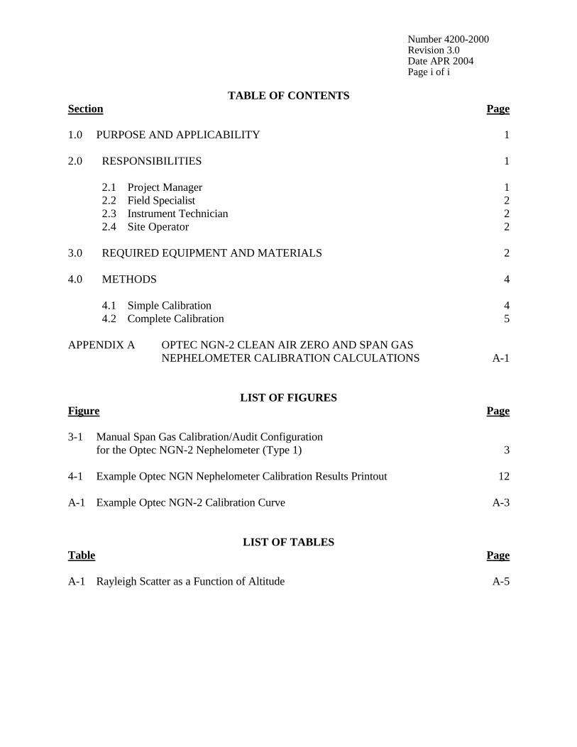
TABLE OF CONTENTS Section Page 1.0 PURPOSE AND APPLICABILITY 1 2.0 RESPONSIBILITIES 1 2.1 Project Manager 1 2.2 Field Specialist 2 2.3 Instrument Technician 2 2.4 Site Operator 2 3.0 REQUIRED EQUIPMENT AND MATERIALS 2 4.0 METHODS 4 4.1 Simple Calibration 4 4.2 Complete Calibration 5 APPENDIX A OPTEC NGN-2 CLEAN AIR ZERO AND SPAN GAS NEPHELOMETER CALIBRATION CALCULATIONS A-1
LIST OF FIGURES Figure Page 3-1 Manual Span Gas Calibration/Audit Configuration for the Optec NGN-2 Nephelometer (Type 1) 3 4-1 Example Optec NGN Nephelometer Calibration Results Printout 12 A-1 Example Optec NGN-2 Calibration Curve A-3
LIST OF TABLES Table Page A-1 Rayleigh Scatter as a Function of Altitude A-5

Number 4200-2000 Revision 3.0 Date APR 2004 Page 1 of 12
1.0 PURPOSE AND APPLICABILITY
This technical instruction (TI) describes the calibration procedures for Optec NGN-2 nephelometers (type 1) operated according to IMPROVE Protocol. Type 1 systems operate with a Campbell Scientific 21X datalogger, and are configured for manual span calibrations. The purpose of nephelometer calibration is to assure quality data capture and minimize data loss by:
• Performing simple calibrations every week. • Performing simple and complete calibrations during acceptance testing, installation,
removal, and annual site visits. • Performing simple and complete calibrations during laboratory testing.
The calibration of Optec NGN-2 nephelometers includes: • Performing a zero calibration using the nephelometer’s internal air filtration system. • Performing a span calibration using a span gas with known scattering properties,
usually SUVA-134a. • Documenting calibration results.
2.0 RESPONSIBILITIES 2.1 PROJECT MANAGER
The project manager shall: • Verify that simple calibrations are performed by the site operator according to the
required schedule, and during: - Acceptance testing of a new instrument - Installation or removal of a nephelometer - Laboratory maintenance - Annual or audit site visits
• Verify that complete calibrations are performed during: - Acceptance testing of a new instrument - Installation or removal of a nephelometer by ARS staff - Laboratory maintenance - Annual or audit site visits

Number 4200-2000 Revision 3.0 Date APR 2004 Page 2 of 12
2.2 FIELD SPECIALIST The field specialist shall:
• Perform a simple calibration and a complete calibration during any site visit. • Document the results of both calibrations on the annual site visit documentation form. • Enter the calibration results in the site-specific Quality Assurance Database.
2.3 INSTRUMENT TECHNICIAN The instrument technician shall:
• Perform a simple calibration and a complete calibration during acceptance testing and laboratory maintenance.
• Maintain a printout of the results of both calibrations. • Enter the calibration results in the site-specific Quality Assurance Database.
2.4 SITE OPERATOR The site operator shall:
• Perform a simple calibration every week. • Record the results of the simple calibration on the NGN-2 Nephelometer/Meteorology
Log Sheet.
3.0 REQUIRED EQUIPMENT AND MATERIALS A span gas calibration system, which includes the following materials, is required for all calibrations:
• Calibration span gas (typically a 30 lb. non-refillable tank of DuPont SUVA-134a refrigerant)
• A pressure regulator capable of providing tight regulation at low pressure (4 psi) and
an adjustable flowmeter compatible and calibrated for use with the span gas are required for providing optimum span gas supply to the NGN-2 nephelometer. (Suggested regulator – Air Products MN E11-N510B). (Suggested flowmeter is the Cole Parmer rotameter MN N014-96ST).
• Calibration gas hoses and fittings to connect the tank, regulator, flowmeter, and
nephelometer (refer to Figure 3-1). The hoses must be compatible with SUVA-134a.

Number 4200-2000 Revision 3.0 Date APR 2004 Page 3 of 12
Figure 3-1. Manual Span Gas Calibration/Audit Configuration for the Optec NGN-2 Nephelometer (Type 1).

Number 4200-2000 Revision 3.0 Date APR 2004 Page 4 of 12
The following additional materials are required to perform a simple calibration: • TI 4100-3100, Routine Site Operator Maintenance Procedures for Optec NGN-2
Nephelometer Systems – Type 1 (IMPROVE Protocol) • NGN-2 Nephelometer/Meteorology Log Sheet (site operator only) • NGN-2 Nephelometer Annual Site Visit Documentation Form (field specialist only)
The following additional equipment and materials are required to perform a complete
calibration:
• HP200LX palmtop computer with Datacomm software -or- A laptop computer with HyperTerminal software
• Nephcom.dcf communications configuration file • Computer-to-nephelometer support system interface cable
4.0 METHODS The two methods of calibrating Optec NGN-2 nephelometers are the simple calibration and the complete calibration. Simple calibrations are initiated by site operators and field specialists to check the operation of the nephelometer system. Complete calibrations are performed by the field specialist or instrument technician during installations, removals, and laboratory testing. These methods are discussed in the following two (2) major subsections: 4.1 Simple Calibration 4.2 Complete Calibration 4.1 SIMPLE CALIBRATION Simple calibration of NGN-2 nephelometers occurs during any of the following checks:
• Site operator initiated zero and span checks • Remote, telephone modem initiated zero and span checks • Field specialist initiated zero and span checks
Simple calibration of NGN-2 nephelometers includes: • Span consisting of ten (10) minutes of gas introduction, then an average of ten (10)
1-minute readings of a span gas with known scattering properties.

Number 4200-2000 Revision 3.0 Date APR 2004 Page 5 of 12
• Clean air zero consisting of five (5) minutes of internal air filtering, then an average of ten (10) 1-minute readings of particle-free air.
Detailed instructions for performing simple calibrations are included in TI 4100-3100,
Routine Site Operator Maintenance Procedures for Optec NGN-2 Nephelometer Systems – Type 1 (IMPROVE Protocol). Record the results of the simple calibration on the Optec NGN-2 Nephelometer/Meteorology Log Sheet (site operator) or the NGN-2 Nephelometer Annual Site Visit Documentation Form (field specialist). 4.2 COMPLETE CALIBRATION Complete calibration of NGN-2 nephelometers occurs during any of the following:
• Acceptance testing of a new instrument • Installation or removal of a nephelometer by ARS staff • Laboratory maintenance • Annual or audit site visits
The HP200LX palmtop computer, or a laptop computer with HyperTerminal software is used by the field specialist to control nephelometer functions and log calibration data during a complete calibration of the NGN-2 nephelometer. Complete calibration includes the following:
• Nephelometer power-on self test (POST) information • Twenty (20) 1-minute clean air zero readings • Twenty (20) 1-minute span readings
Procedures for initiating a complete calibration include: • Attaching the span gas system to the nephelometer. • Attaching the palmtop computer or laptop computer to the nephelometer support
system. • Executing the specific procedures outlined below.

Number 4200-2000 Revision 3.0 Date APR 2004 Page 6 of 12
Specific procedures are detailed as follows:
ATTACH SPAN GAS SYSTEM
Attach the span gas system to the nephelometer as follows: • Connect the regulator input hose to the calibration gas tank
outlet connector. • Connect the flowmeter input hose (bottom) to the in-line filter
assembly, then to the calibration gas regulator output connector.
• Connect the span gas hose from the nephelometer to the
output connector (top) of the rotameter. • Turn the flowmeter adjustment knob to the OFF position
(fully clockwise).
ATTACH COMPUTER Attach the palmtop or laptop computer to the nephelometer support system (field calibration) or directly to the nephelometer (lab calibration) using the appropriate interface cable. The cable must be attached to the bottom of the datalogger at the connector labeled “Terminal” (AMP-A directly behind the connector labeled “Phone”).
SETUP COMMUNICATION SETTINGS
HP200LX with Datacomm software Perform the following steps to establish communications with the nephelometer: • Turn the computer on. • Press the MORE key. • Close all active applications except Filer. (To close an
application, highlight the icon for that application and press F6).
• After all applications (except Filer) have been closed,
highlight the Datacomm icon and press F5 or <Enter>. • Press the Menu key. • Move the cursor to Connect and press <Enter>. • Move the cursor down to Settings and press <Enter>. • Press O to list stored configuration files. • Use the <Tab> key to move the cursor to the listed files.
Then highlight the nephelometer communication configuration file Nephcom.dcf.

Number 4200-2000 Revision 3.0 Date APR 2004 Page 7 of 12
SETUP COMMUNICATION SETTINGS (continued)
• Press F10. • Verify that the palmtop computer or laptop computer
configuration settings are correct:
Baud: 9600 Data Bits: 8 Interface: Com1 Stop Bits: 1 Parity: None
• If the palmtop computer configuration settings are not correct, use the <Tab> key to move the cursor from one parameter (e.g., Baud) to another parameter (e.g., Parity) and then move the cursor to the proper setting for that parameter.
• When the settings are correct, press F10. Laptop with HyperTerminal Software Perform the following steps to establish communications with the nephelometer:
• Turn the computer on.
• Open the HyperTerminal program. HyperTerminal comes with all versions of Windows operating systems and is located in the Windows Start Menu, Programs/Accessories/ Communications.
• Follow the on-screen prompts for the area code entry and connect using the port that will be connected to the nephelometer directly.
• Verify that the com port configuration settings are correct: Baud: 9600 Data Bits: 8 Interface: Com1 Stop Bits: 1 Parity: None
• If the com port configuration settings are not correct, update the parameter with the proper setting.
OPEN A DATA FILE
HP200LX with Datacomm software Perform the following steps to open a data file: • Press the Menu key. • Move the cursor to Connect and press <Enter>. • Press F5. • Press the <BackSpace> key to clear the filename entry box.

Number 4200-2000 Revision 3.0 Date APR 2004 Page 8 of 12
OPEN A DATA FILE (continued)
• Type the desired filename into the entry box using the following format: C:\_Dat\sitemmyy.dat, where site is the site abbreviation, mm is the month, and yy is the year. NOTE: STOPCAP should be indicated on the bottom status bar on the palmtop. Note that if you have to start over for nay reason, be sure to use a different file name.
• Press <Enter>. Laptop with HyperTerminal software Perform the following steps to save a data file: • Select Transfer, then Capture Text. • Click Browse to select the area to save to, and type the
desired filename into the entry box using the following format: C:\path\sitemmyy.dat, where site is the site abbreviation, mm is the month, and yy is the year. Note that if you have to start over for any reason, be sure to use a different file name.
• Press <Enter>.
PERFORM A MANUAL CALIBRATION
Perform the following calibration steps: • Reset the nephelometer by interrupting power to the
nephelometer (press the red reset button on the datalogger panel).
• Quickly press ^C several times to get the nephelometer prompt (>).
• Press <Enter> once to get a clean line. • If the nephelometer will not respond, disconnect the palmtop
or laptop computer cable from the datalogger system. Install the circular connector adapter between the cable and the datalogger system and repeat the two preceding steps.
• Press FN (function) and ZOOM (spacebar) to see all of the printed lines.
• Verify that the nephelometer settings, date, and time are correct:
SN (serial Number) = # Run Mode = 3 Intervals = 72 Date and Time = current date and time Auto Span = 1 Baud Rate = 1200 Auto Test = 1

Number 4200-2000 Revision 3.0 Date APR 2004 Page 9 of 12
PERFORM A MANUAL CALIBRATION (continued)
• Document any incorrect nephelometer settings. • Verify that the nephelometer is set to local standard time. If
the time is not correct, reset the nephelometer clock by entering the correct hour and minute. Note that the nephelometer uses a 24-hour clock (e.g., 4:30 pm would be entered as 16 hours, 30 minutes).
• When the nephelometer date, time, and configuration settings
are correct, enter POST at the nephelometer prompt. The current nephelometer settings will be displayed on the computer screen and written to the open capture file.
• Manually perform the POST functions by typing the following
commands, and pressing the <Enter> key after each command:
DOOR OPEN LAMP ON FAN ON FAN OFF SOL ON SOL OFF VALVE ON VALVE OFF PUMP ON PUMP OFF
• Close the nephelometer door by typing DOOR CLOSE. • Turn pump on by typing PUMP ON. • Type 1 TO INTEG. • Type 1 20 (minutes in field) DO WORK LOOP. • After the clean air calibration cycle is complete, perform a
span gas calibration. Before turning the gas on, verify that the flowmeter is turned off (fully clockwise). Turn the span gas tank valve (counter-clockwise) ½ turn and set the regulator to 4 psi.
• Turn the nephelometer valve on by typing VALVE ON and
slowly adjust the flowmeter to 20 mm. • Type 1 20 (minutes in the field) DO WORK LOOP. • After the span calibration is finished, turn the span gas tank
valve off.

Number 4200-2000 Revision 3.0 Date APR 2004 Page 10 of 12
PERFORM A MANUAL CALIBRATION (continued)
• Disconnect the supply hose between the flowmeter and tank. • Close the flowmeter (fully clockwise). • Perform POST calibration functions by typing the following
commands (press the <Enter> key after each command).
DOOR OPEN FAN ON LAMP OFF SOL ON VALVE OFF
To remove SUVA gas from the measurement chamber, let the instrument run for approximately five minutes, and type the following commands (press the <Enter> key after each command): PUMP OFF FAN OFF SOL OFF DOOR CLOSE • Press FN (function) and ZOOM (spacebar) to see the bottom
status bar.
STOP FILE CAPTURE
HP200LX with Datacomm software Perform the following steps to stop file capture: • After obtaining a valid calibration, press F5 to close the
capture file. The bottom status bar on the palmtop should indicate: CAPTURE.
• Press Menu, highlight Quit, and press <Enter> . • Press the Filer key on the computer, then press F5. Type or
highlight the correct path, (e.g., C:\Dat). Type or highlight the correct file name and enter.
• Press F8 (View) to verify that the data were captured. • Use the arrow keys to move through the entire file. • Press F8 to close the viewed file. • Press Menu, highlight Quit, and press <Enter> to close the
file. • Press Menu, highlight Quit, and press <Enter> to close
applications and return to the opening screen. • Turn the computer off and remove the cables.

Number 4200-2000 Revision 3.0 Date APR 2004 Page 11 of 12
STOP FILE CAPTURE (continued)
Laptop with HyperTerminal software Perform the following steps to stop file capture: • Select Transfer, then under Capture Text select Stop. • Use Windows Explorer to find the save file and open the file
with WordPad to verify that the data were captured. • Close the viewed file. • Close the HyperTerminal program. • Turn the computer off and remove the cables.
DOCUMENTING THE CALIBRATION
Place a printout of the calibration results in the instrument-specific nephelometer maintenance log book. An example of the printout is shown in Figure 4-1. Enter the results in the site-specific Quality Assurance Database.

Number 4200-2000 Revision 3.0 Date APR 2004 Page 12 of 12
RTL CPM VERSION - FOR OPTEC SBC COPYRIGHT 1992 OPTEC, INC. NGN-2 OPERATING SYSTEM VERSION: NEPH1056 SN = 21 RUN MODE = 3 INTERVALS = 72 DATE & TIME (YR-MO-DAY HR-MIN) = 960509 1641 AUTO SPAN (1 ON / 0 OFF) 1 STORED BAUD RATE = 1200 AUTO TEST (1 ON / 0 OFF) = 1 TOTAL RUN TIME = 4037 HOURS CSUM = 23 ROMTOP = 23 Column 1 2 3 4 5 6 7 8 >LAMP-ON PUMP ON 1 TO INTEG >1 15 DO WORK LOOP 1 131 4005 65 1 23.66 960509 1642 1 124 3989 62 1 23.72 960509 1643 1 123 3978 61 1 23.78 960509 1644 1 116 3971 58 1 23.81 960509 1645 1 120 3968 60 1 23.78 960509 1646 1 120 3967 60 1 23.84 960509 1647 1 118 3967 59 1 23.81 960509 1648 1 117 3967 59 1 23.84 960509 1649 1 119 3967 60 1 23.84 960509 1650 1 114 3967 57 1 23.87 960509 1651 1 118 3967 59 1 23.84 960509 1652 1 121 3968 61 1 23.90 960509 1653 1 117 3973 59 1 23.95 960509 1654 1 117 3979 58 1 23.92 960509 1655 1 120 3985 60 1 23.95 960509 1656 >VALVE ON >1 15 DO WORK LOOP 1 144 3979 72 1 24.13 960509 1702 1 189 3980 95 1 24.19 960509 1703 1 220 3982 110 1 24.22 960509 1704 1 233 3983 117 1 24.28 960509 1705 1 241 3984 121 1 24.34 960509 1706 1 244 3986 122 1 24.39 960509 1707 1 245 3988 122 1 24.42 960509 1708 1 246 3991 123 1 24.51 960509 1709 1 246 3993 123 1 24.54 960509 1710 1 246 3995 123 1 24.57 960509 1711 1 247 3997 123 1 24.60 960509 1712 1 248 3999 124 1 24.69 960509 1713 1 246 4000 123 1 24.75 960509 1714 1 246 4001 123 1 24.78 960509 1715 1 248 4002 124 1 24.86 960509 1716 >LAMP OFF PUMP OFF VALVE OFF Column Description 1 Status: 1 = ambient air measurement 2 = clean air calibration 3 = span gas calibration 4 = lamp low or burned out 5 = rain 6 = chopper motor failure 7 = span/clean air calibration in process (D/A channel-2 output only) 8 = fog level reached 2 Raw scattered light value 3 Raw lamp brightness value 4 Normalized scattered light value 5 Integration time in minutes 6 Temperature (°C) 7 Year-Month-Day 8 Hour-Minute using 24-hour clock
Figure 4-1. Example Optec NGN Nephelometer Calibration Results Printout.

Number 4200-2000 Revision 3.0 Date APR 2004 Page A-1 of A-5
APPENDIX A
Optec NGN-2 Clean-Air Zero and Span Gas
Nephelometer Calibration Calculations

Number 4200-2000 Revision 3.0 Date APR 2004 Page A-2 of A-5
Optec NGN-2 Clean-Air Zero and Span Gas
Nephelometer Calibration Calculations
1) Calibration of the nephelometer allows conversion of the reading in counts to bscat. This is a two-step process:
• The nephelometer reading in counts is converted to multiples of Rayleigh; and • The calculated multiple of Rayleigh is multiplied by the Rayleigh coefficient (specific
for each elevation) to provide bscat. 2) Two calibration points are required (see accompanying Optec NGN-2 Manual Calibration Procedures): 1) A clean air (Rayleigh) value obtained by recirculating air through the nephelometer’s internal clean air filter, and 2) an upscale span value obtained by introducing a gas of known scattering properties to the nephelometer chamber. 3) Nephelometer response to scattering can be represented by the linear equation: where: y = normalized nephelometer reading in counts m = slope of calibration line
x = multiple of Rayleigh scattering b = nephelometer wall scattering in counts
m and b are calculated as follows:
where: Cspan = nephelometer counts during upscale span calibration (in counts) Czero = nephelometer counts during clean air calibration (in counts) Sspan = span gas multiple of Rayleigh scattering (e.g., F12 = 15.3) Szero = clean air multiple of Rayleigh scattering (always 1.0)
An example calibration curve is provided as Figure A-1. Curves will vary between instruments.
For the measured calibration values displayed in Figure A-1, of 35 counts for clean air and 200 counts for Freon-12:
bmxy +=
zerozerozerospan
zerospan SmCandbSS
CCm ∗−=
−
−=
5.2354.11 == andbm

Number 4200-2000 Revision 3.0 Date APR 2004 Page A-3 of A-5
Figure A-1. Example Optec NGN-2 Calibration Curve.
Number 4200-2000 Revision 3.0 Date APR 2004 Page A-4 of A-5
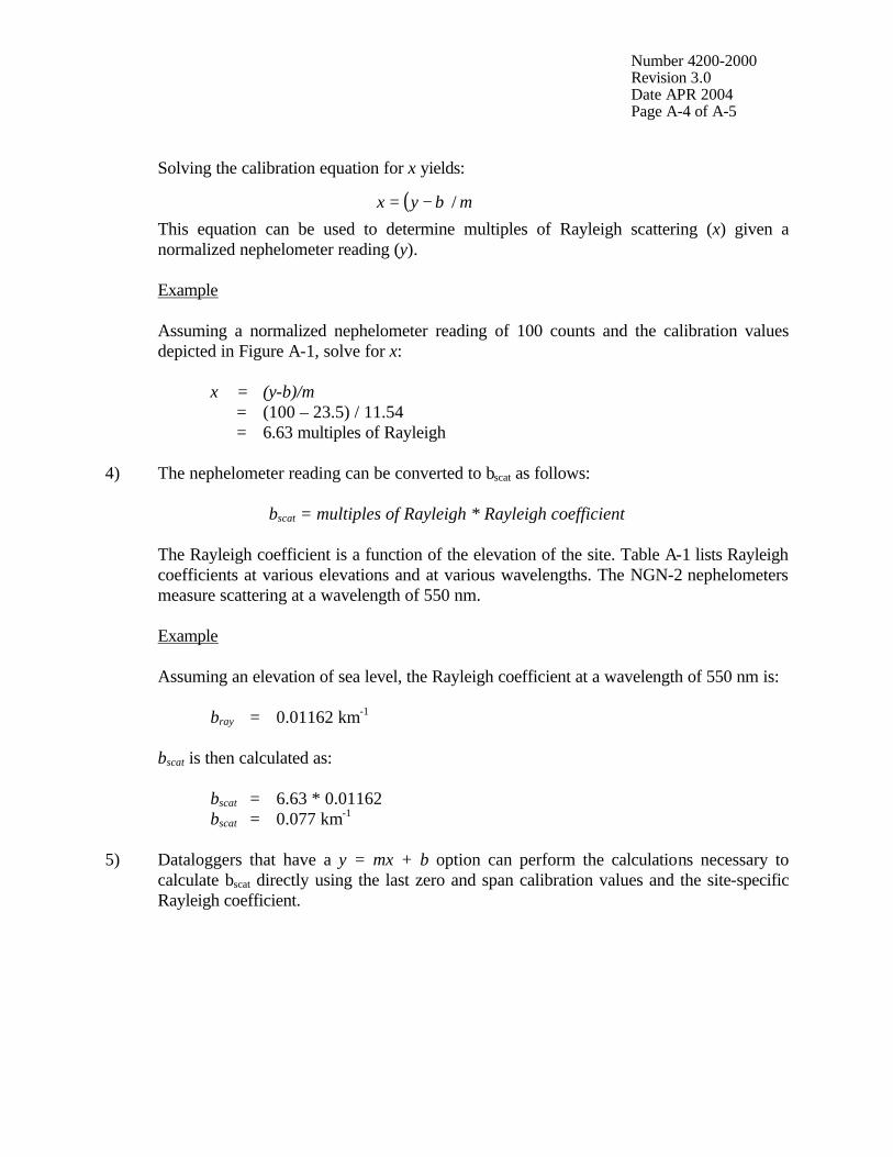
Solving the calibration equation for x yields:
This equation can be used to determine multiples of Rayleigh scattering (x) given a normalized nephelometer reading (y).
Example
Assuming a normalized nephelometer reading of 100 counts and the calibration values depicted in Figure A-1, solve for x:
x = (y-b)/m
= (100 – 23.5) / 11.54 = 6.63 multiples of Rayleigh
4) The nephelometer reading can be converted to bscat as follows:
bscat = multiples of Rayleigh * Rayleigh coefficient
The Rayleigh coefficient is a function of the elevation of the site. Table A-1 lists Rayleigh coefficients at various elevations and at various wavelengths. The NGN-2 nephelometers measure scattering at a wavelength of 550 nm.
Example Assuming an elevation of sea level, the Rayleigh coefficient at a wavelength of 550 nm is: bray = 0.01162 km-1
bscat is then calculated as:
bscat = 6.63 * 0.01162 bscat = 0.077 km-1 5) Dataloggers that have a y = mx + b option can perform the calculations necessary to
calculate bscat directly using the last zero and span calibration values and the site-specific Rayleigh coefficient.
( ) mbyx /−=

Number 4200-2000 Revision 3.0 Date APR 2004 Page A-5 of A-5
Table A-1
Rayleigh Scatter in km-1 as a Function of Altitude
Wavelength Altitude (m) UV (405) Blue (450) Green (550) Red (630)
0 0.03952181 0.02593026 0.01162000 0.00674986 100 0.03915788 0.02569148 0.01151300 0.00668770 200 0.03879395 0.02545271 0.01140600 0.00662555 300 0.03843003 0.02521394 0.01129900 0.00656340 400 0.03806610 0.02497517 0.01119200 0.00650124 500 0.03770217 0.02473639 0.01108500 0.00643909 600 0.03733824 0.02449762 0.01097800 0.00637693 700 0.03697432 0.02425885 0.01087100 0.00631478 800 0.03661039 0.02402008 0.01076400 0.00625262 900 0.03624646 0.02378130 0.01065700 0.00619047
1000 0.03588254 0.02354253 0.01055000 0.00612831 1100 0.03554242 0.02331938 0.01045000 0.00607023 1200 0.03520230 0.02309623 0.01035000 0.00601214 1300 0.03486218 0.02287308 0.01025000 0.00595405 1400 0.03452206 0.02264992 0.01015000 0.00589596 1500 0.03418194 0.02242677 0.01005000 0.00583787 1600 0.03384182 0.02220362 0.00995000 0.00577978 1700 0.03350170 0.02198047 0.00985000 0.00572170 1800 0.03316159 0.02175732 0.00975000 0.00566361 1900 0.03282147 0.02153416 0.00965000 0.00560552
2000 0.03248135 0.02131101 0.00955000 0.00554743 2100 0.03216844 0.02110571 0.00945800 0.00549399 2200 0.03185553 0.02090041 0.00936600 0.00544055 2300 0.03154262 0.02069511 0.00927400 0.00538711 2400 0.03122971 0.02048981 0.00918200 0.00533367 2500 0.03091680 0.02028451 0.00909000 0.00528023 2600 0.03060389 0.02007921 0.00899800 0.00522678 2700 0.03029098 0.01987391 0.00890600 0.00517334 2800 0.02997807 0.01966861 0.00881400 0.00511990 2900 0.02966516 0.01946331 0.00872200 0.00506646
3000 0.02935225 0.01925801 0.00863000 0.00501302 3100 0.02903934 0.01905271 0.00853800 0.00495958 3200 0.02872644 0.01884741 0.00844600 0.00490614 3300 0.02841353 0.01864211 0.00835400 0.00485270 3400 0.02810062 0.01843681 0.00826200 0.00479925 3500 0.02778771 0.01823152 0.00817000 0.00474581 3600 0.02747480 0.01802622 0.00807800 0.00469237 3700 0.02716189 0.01782092 0.00798600 0.00463893 3800 0.02684898 0.01761562 0.00789400 0.00458549 3900 0.02653607 0.01741032 0.00780200 0.00453205
4000 0.02622316 0.01720502 0.00771000 0.00447861 4100 0.02591025 0.01699972 0.00761800 0.00442517 4200 0.02559734 0.01679442 0.00752600 0.00437172 4300 0.02528443 0.01658912 0.00743400 0.00431828 4400 0.02497152 0.01638382 0.00734200 0.00426484

QUALITY ASSURANCE/QUALITY CONTROL DOCUMENTATION SERIES
TITLE
CALIBRATION OF OPTEC NGN-2 NEPHELOMETERS – TYPE 2 (IMPROVE PROTOCOL)
TYPE
TECHNICAL INSTRUCTION
NUMBER
4200-2005
DATE
APRIL 2004
AUTHORIZATIONS
TITLE NAME SIGNATURE
ORIGINATOR E. Marty Mills
PROJECT MANAGER Mark Tigges
PROGRAM MANAGER David L. Dietrich
QA MANAGER Gloria S. Mercer
OTHER
REVISION HISTORY
REVISION NO.
CHANGE DESCRIPTION DATE AUTHORIZATIONS

Number 4200-2005 Revision 0 Date APR 2004 Page i of i
TABLE OF CONTENTS Section Page 1.0 PURPOSE AND APPLICABILITY 1 2.0 RESPONSIBILITIES 1 2.1 Project Manager 1 2.2 Field Specialist 2 2.3 Instrument Technician 2 2.4 Site Operator 2 3.0 REQUIRED EQUIPMENT AND MATERIALS 2 4.0 METHODS 4 4.1 Automatic Simple Calibration 4 4.2 Manual Simple Calibration 5 4.3 Complete Calibration 5 APPENDIX A OPTEC NGN-2 CLEAN AIR ZERO AND SPAN GAS NEPHELOMETER CALIBRATION CALCULATIONS A-1
LIST OF FIGURES Figure Page 3-1 Automatic Span Gas Calibration System for the Optec NGN-2 Nephelometer (Type 2) 3 4-1 Example Optec NGN Nephelometer Calibration Results Printout 12 A-1 Example Optec NGN-2 Calibration Curve A-3
LIST OF TABLES Table Page A-1 Rayleigh Scatter as a Function of Altitude A-5

Number 4200-2005 Revision 0 Date APR 2004 Page 1 of 12
1.0 PURPOSE AND APPLICABILITY
This technical instruction (TI) describes the calibration procedures for Optec NGN-2 nephelometers (type 2) operated according to IMPROVE Protocol. Type 2 systems operate with a Campbell Scientific 23X datalogger, and can be configured for manual or automatic span calibrations. The purpose of nephelometer calibration is to assure quality data capture and minimize data loss by:
• Performing automatic simple calibrations every week. • Performing manual simple calibrations during monthly site visits. • Performing simple and complete calibrations during acceptance testing, installation,
removal, and annual site visits. • Performing simple and complete calibrations during laboratory testing.
The calibration of Optec NGN-2 nephelometers includes: • Performing a zero calibration using the nephelometer’s internal air filtration system. • Performing a span calibration using a span gas with known scattering properties,
usually SUVA-134a. • Documenting calibration results.
2.0 RESPONSIBILITIES 2.1 PROJECT MANAGER
The project manager shall: • Verify that the nephelometer and datalogging system are running automatic
calibrations every seven (7) days, as scheduled. • Verify that simple calibrations are performed by the site operator according to the
required schedule, and during: - Acceptance testing of a new instrument - Installation or removal of a nephelometer - Laboratory maintenance - Annual or audit site visits
• Verify that complete calibrations are performed during: - Acceptance testing of a new instrument - Installation or removal of a nephelometer by ARS staff - Laboratory maintenance - Annual or audit site visits
Number 4200-2005 Revision 0 Date APR 2004 Page 2 of 12
2.2 FIELD SPECIALIST The field specialist shall:
• Perform a simple calibration and a complete calibration during any site visit. • Document the results of both calibrations on the annual site visit documentation form. • Enter the calibration results in the site-specific Quality Assurance Database.
2.3 INSTRUMENT TECHNICIAN The instrument technician shall:
• Perform a simple calibration and a complete calibration during acceptance testing and laboratory maintenance.
• Maintain a printout of the results of both calibrations. • Enter the calibration results in the site-specific Quality Assurance Database.
2.4 SITE OPERATOR The site operator shall:
• Verify that the automatic calibration system is operating properly. • Perform a simple calibration at monthly site visits. • Record the results of the simple calibration on the NGN-2 Nephelometer/Meteorology
Log Sheet.
3.0 REQUIRED EQUIPMENT AND MATERIALS A span gas calibration system, which includes the following materials, is required for all calibrations:
• Calibration span gas (typically a 30 lb. non-refillable tank of DuPont SUVA-134a refrigerant).
• A pressure regulator capable of providing tight regulation at low pressure (4 psi) and
an adjustable flowmeter compatible and calibrated for use with the span gas are required for providing optimum span gas supply to the NGN-2 nephelometer. (Suggested regulator – Air Products MN E11-N510B). (Suggested flowmeter is the Cole Parmer rotameter MN N014-96ST).
• Calibration span gas inlet and outlet valves and inlet and outlet relays. • Calibration gas hoses and fittings to connect the tank, regulator, flowmeter, and
nephelometer (refer to Figure 3-1). The hoses must be compatible with SUVA-134a.

Number 4200-2005 Revision 0 Date APR 2004 Page 3 of 12
Figure 3-1. Automatic Span Gas Calibration System
for the Optec NGN-2 Nephelometer (Type 2).
Environmental Enclosures
Flowmeter
Span Gas Outlet Purge Valve
Gas Regulator
Power Supply
DuPont SUVA 134a Refrigerant Gas (30 lb)
Tank Valve
Refrigerant Hose
Outlet Relay
Span Gas Inlet Valve
Inlet Relay

Number 4200-2005 Revision 0 Date APR 2004 Page 4 of 12
The following additional materials are required to perform a simple calibration: • TI 4100-3105, Routine Site Operator Maintenance Procedures for Optec NGN-2
Nephelometer Systems – Type 2 (IMPROVE Protocol) • NGN-2 Nephelometer/Meteorology Log Sheet (site operator only) • NGN-2 Nephelometer Annual Site Visit Documentation Form (field specialist only)
The following additional equipment and materials are required to perform a complete
calibration:
• HP200LX palmtop computer with Datacomm software -or- A laptop computer with HyperTerminal software
• Nephcom.dcf communications configuration file • Computer-to-nephelometer support system interface cable
4.0 METHODS The three methods of calibrating Type 2 Optec NGN-2 nephelometers are the automatic simple calibration, the manual simple calibration, and the complete calibration. Automatic simple calibrations are set up to be initiated by the datalogging and control subsystem on a weekly basis (every seven days as scheduled). Manual simple calibrations are initiated by site operators and field specialists to check the operation of the nephelometer system while on site. Complete calibrations are performed by the field specialist or instrument technician during installations, removals, and laboratory testing. These methods are discussed in the following three (3) major subsections: 4.1 Automatic Simple Calibration 4.2 Manual Simple Calibration 4.3 Complete Calibration 4.1 AUTOMATIC SIMPLE CALIBRATION Automatic simple calibrations of NGN-2 nephelometers occur every seven (7) days at the scheduled time, once they are scheduled by the site operator or field specialist. Detailed instructions for scheduling the automatic simple calibrations are included in TI 4100-3105, Routine Site Operator Maintenance Procedures for Optec NGN-2 Nephelometer Systems – Type 2 (IMPROVE Protocol).
Automatic simple calibration of NGN-2 nephelometers includes: • Span consisting of ten (10) minutes of gas introduction, then an average of ten (10)
1-minute readings of a span gas with known scattering properties. • Clean air zero consisting of five (5) minutes of internal air filtering, then an average of
ten (10) 1-minute readings of particle-free air.
Results of the automatic simple calibration are recorded by the Campbell 23X datalogger.

Number 4200-2005 Revision 0 Date APR 2004 Page 5 of 12
4.2 MANUAL SIMPLE CALIBRATION Manual simple calibration of NGN-2 nephelometers occurs during any of the following checks:
• Site operator initiated zero and span checks • Remote, telephone modem initiated zero and span checks • Field specialist initiated zero and span checks
Manual calibration of NGN-2 nephelometers includes the same measurement readings and
procedures as in automatic simple calibration (see Section 4.1): • Span consisting of ten (10) minutes of gas introduction, then an average of ten (10)
1-minute readings of a span gas with known scattering properties. • Clean air zero consisting of five (5) minutes of internal air filtering, then an average of
ten (10) 1-minute readings of particle-free air. Detailed instructions for performing simple calibrations are included in TI 4100-3105,
Routine Site Operator Maintenance Procedures for Optec NGN-2 Nephelometer Systems – Type 2 (IMPROVE Protocol). Record the results of the simple calibration on the Optec NGN-2 Nephelometer/Meteorology Log Sheet (site operator) or the NGN-2 Nephelometer Annual Site Visit Documentation Form (field specialist). 4.3 COMPLETE CALIBRATION Complete calibration of NGN-2 nephelometers occurs during any of the following:
• Acceptance testing of a new instrument • Installation or removal of a nephelometer by ARS staff • Laboratory maintenance • Annual or audit site visits
The HP200LX palmtop computer or a laptop computer with HyperTerminal software is used by the field specialist to control nephelometer functions and log calibration data during a complete calibration of the NGN-2 nephelometer. Complete calibration includes the following:
• Nephelometer power-on self test (POST) information • Twenty (20) 1-minute clean air zero readings • Twenty (20) 1-minute span readings

Number 4200-2005 Revision 0 Date APR 2004 Page 6 of 12
Procedures for initiating a complete calibration include: • Attaching the span gas system to the nephelometer. • Attaching the palmtop computer or laptop computer to the nephelometer support
system. • Executing the specific procedures outlined below.
Specific procedures are detailed as follows:
ATTACH SPAN GAS SYSTEM
For laboratory calibration, attach the span gas system to the nephelometer as follows: • Connect the regulator input hose to the calibration gas tank
outlet connector. • Connect the flowmeter input hose (bottom) to the calibration
gas regulator output connector. • Connect the span gas hose from the nephelometer to the
output connector (top) of the flowmeter. • Turn the flowmeter adjustment knob to the OFF position
(fully clockwise). For field calibration, the span gas system is already connected to the nephelometer.
ATTACH COMPUTER Attach the palmtop or laptop computer to the nephelometer support system (field calibration) or directly to the nephelometer (lab calibration) using the appropriate interface cable. The cable must be attached to the serial connection on the connector panel on the bottom of the datalogger enclosure.
SETUP COMMUNICATION SETTINGS
HP200LX with Datacomm software Perform the following steps to establish communications with the nephelometer: • Turn the computer on. • Press the MORE key. • Close all active applications except Filer. (To close an
application, highlight the icon for that application and press F6).

Number 4200-2005 Revision 0 Date APR 2004 Page 7 of 12
SETUP COMMUNICATION SETTINGS (continued)
• After all applications (except Filer) have been closed, highlight the Datacomm icon and press F5 or <Enter>.
• Press the Menu key. • Move the cursor to Connect and press <Enter>. • Move the cursor down to Settings and press <Enter>. • Press O to list stored configuration files. • Use the <Tab> key to move the cursor to the listed files.
Then highlight the nephelometer communication configuration file Nephcom.dcf.
• Press F10. • Verify that the palmtop computer configuration settings are correct:
Baud: 9600 Data Bits: 8 Interface: Com1 Stop Bits: 1 Parity: None
• If the palmtop computer configuration settings are not correct, use the <Tab> key to move the cursor from one parameter (e.g., Baud) to another parameter (e.g., Parity) and then move the cursor to the proper setting for that parameter.
• When the settings are correct, press F10. Laptop with HyperTerminal software Perform the following steps to establish communications with the nephelometer: • Turn the computer on. • Open the HyperTerminal program. HyperTerminal comes
with all versions of Windows operating systems and is located in the Windows Start Menu, Programs/Accessories/ Communications.
• Follow the on-screen prompts for the area code entry and
connect using the port that will be connected to the nephelometer directly.
• Verify that the com port configuration settings are correct:
Baud: 9600 Data Bits: 8 Interface: Com1 Stop Bits: 1 Parity: None
• If the com port configuration settings are not correct, update the parameter with the proper setting.

Number 4200-2005 Revision 0 Date APR 2004 Page 8 of 12
OPEN A DATA FILE HP200LX with Datacomm software Perform the following steps to open a data file: • Press the Menu key. • Move the cursor to Connect and press <Enter>. • Press F5. • Press the <BackSpace> key to clear the filename entry box. • Type the desired filename into the entry box using the
following format: C:\_Dat\sitemmyy.dat, where site is the site abbreviation, mm is the month, and yy is the year. NOTE: STOPCAP should be indicated on the bottom status bar on the palmtop. Note that if you have to start over for nay reason, be sure to use a different file name.
• Press <Enter>. Laptop with HyperTerminal software Perform the following steps to save a data file: • Select Transfer, then Capture Text. • Click Browse to select the area to save to, and type the
desired filename into the entry box using the following format: C:\path\sitemmyy.dat, where site is the site abbreviation, mm is the month, and yy is the year. Note that if you have to start over for any reason, be sure to use a different file name.
• Press <Enter>.
PERFORM A MANUAL CALIBRATION
Perform the following calibration steps: • Reset the nephelometer by pressing *6A0 to enter the port
locations. Then press 1 to turn the nephelometer off and 1 again to restart the nephelometer.
• Quickly press ^C several times to get the nephelometer
prompt (>). • Press <Enter> once to get a clean line. • If the nephelometer will not respond, disconnect the palmtop
or laptop computer cable from the datalogger system. Install the null modem adapter between the cable and the datalogger system and repeat the two preceding steps.

Number 4200-2005 Revision 0 Date APR 2004 Page 9 of 12
PERFORM A MANUAL CALIBRATION (continued)
• Press FN (function) and ZOOM (spacebar) to see all of the printed lines.
• Verify that the nephelometer settings, date, and time are correct:
SN (serial Number) = # Run Mode = 3 Intervals = 72 Date and Time = current date and time Auto Span = 1 Baud Rate = 1200 Auto Test = 1
• Document any incorrect nephelometer settings. • Verify that the nephelometer is set to local standard time. If
the time is not correct, reset the nephelometer clock by entering the correct hour and minute. Note that the nephelometer uses a 24-hour clock (e.g., 4:30 pm would be entered as 16 hours, 30 minutes).
• When the nephelometer date, time, and configuration settings
are correct, enter POST at the nephelometer prompt. The current nephelometer settings will be displayed on the computer screen and written to the open capture file.
• Manually perform the POST functions by typing the following
commands, and pressing the <Enter> key after each command:
DOOR OPEN LAMP ON FAN ON FAN OFF SOL ON SOL OFF VALVE ON VALVE OFF PUMP ON PUMP OFF
• Close the nephelometer door by typing DOOR CLOSE. • Turn pump on by typing PUMP ON. • Type 1 TO INTEG. • Type 1 20 (minutes in field) DO WORK LOOP.

Number 4200-2005 Revision 0 Date APR 2004 Page 10 of 12
PERFORM A MANUAL CALIBRATION (continued)
• After the clean air calibration cycle is complete, perform a span gas calibration by entering 2 and 3 on the 23X keypad to open the solenoid valves.
• Turn the nephelometer valve on by typing VALVE ON and
slowly adjust the flowmeter to 20 mm. • Type 1 20 (minutes in the field) DO WORK LOOP. • After the span calibration is finished, turn off the solenoid
valves by resetting Ports 2 and 3 to 0 using the 23X keypad. • Perform POST calibration functions by typing the following
commands (press the <Enter> key after each command).
DOOR OPEN FAN ON LAMP OFF SOL ON VALVE OFF
To remove SUVA gas from the measurement chamber, let the instrument run for approximately five minutes, and type the following commands (press the <Enter> key after each command): PUMP OFF FAN OFF SOL OFF DOOR CLOSE • Press FN (function) and ZOOM (spacebar) to see the bottom
status bar.
STOP FILE CAPTURE
HP200LX with Datacomm software Perform the following steps to stop file capture: • After obtaining a valid calibration, press F5 to close the
capture file. The bottom status bar on the palmtop should indicate: CAPTURE.
• Press Menu, highlight Quit, and press <Enter> . • Press the Filer key on the computer, then press F5. Type or
highlight the correct path, (e.g., C:\Dat). Type or highlight the correct file name and enter.
• Press F8 (View) to verify that the data were captured. • Use the arrow keys to move through the entire file. • Press F8 to close the viewed file.

Number 4200-2005 Revision 0 Date APR 2004 Page 11 of 12
STOP FILE CAPTURE (continued)
• Press Menu, highlight Quit, and press <Enter> to close the file.
• Press Menu, highlight Quit, and press <Enter> to close
applications and return to the opening screen. • Turn the computer off and remove the cables. Laptop with HyperTerminal software Perform the following steps to stop file capture: • Select Transfer, then under Capture Text select Stop. • Use Windows Explorer to find the save file and open the file
with WordPad to verify that the data were captured. • Close the viewed file. • Close the HyperTerminal program. • Turn the computer off and remove the cables.
DOCUMENTING THE CALIBRATION
Place a printout of the calibration results in the instrument-specific nephelometer maintenance log book. An example of the printout is shown in Figure 4-1. Enter the results in the site-specific Quality Assurance Database.

Number 4200-2005 Revision 0 Date APR 2004 Page 12 of 12
RTL CPM VERSION - FOR OPTEC SBC COPYRIGHT 1992 OPTEC, INC. NGN-2 OPERATING SYSTEM VERSION: NEPH1056 SN = 21 RUN MODE = 3 INTERVALS = 72 DATE & TIME (YR-MO-DAY HR-MIN) = 960509 1641 AUTO SPAN (1 ON / 0 OFF) 1 STORED BAUD RATE = 1200 AUTO TEST (1 ON / 0 OFF) = 1 TOTAL RUN TIME = 4037 HOURS CSUM = 23 ROMTOP = 23 Column 1 2 3 4 5 6 7 8 >LAMP-ON PUMP ON 1 TO INTEG >1 15 DO WORK LOOP 1 131 4005 65 1 23.66 960509 1642 1 124 3989 62 1 23.72 960509 1643 1 123 3978 61 1 23.78 960509 1644 1 116 3971 58 1 23.81 960509 1645 1 120 3968 60 1 23.78 960509 1646 1 120 3967 60 1 23.84 960509 1647 1 118 3967 59 1 23.81 960509 1648 1 117 3967 59 1 23.84 960509 1649 1 119 3967 60 1 23.84 960509 1650 1 114 3967 57 1 23.87 960509 1651 1 118 3967 59 1 23.84 960509 1652 1 121 3968 61 1 23.90 960509 1653 1 117 3973 59 1 23.95 960509 1654 1 117 3979 58 1 23.92 960509 1655 1 120 3985 60 1 23.95 960509 1656 >VALVE ON >1 15 DO WORK LOOP 1 144 3979 72 1 24.13 960509 1702 1 189 3980 95 1 24.19 960509 1703 1 220 3982 110 1 24.22 960509 1704 1 233 3983 117 1 24.28 960509 1705 1 241 3984 121 1 24.34 960509 1706 1 244 3986 122 1 24.39 960509 1707 1 245 3988 122 1 24.42 960509 1708 1 246 3991 123 1 24.51 960509 1709 1 246 3993 123 1 24.54 960509 1710 1 246 3995 123 1 24.57 960509 1711 1 247 3997 123 1 24.60 960509 1712 1 248 3999 124 1 24.69 960509 1713 1 246 4000 123 1 24.75 960509 1714 1 246 4001 123 1 24.78 960509 1715 1 248 4002 124 1 24.86 960509 1716 >LAMP OFF PUMP OFF VALVE OFF Column Description 1 Status: 1 = ambient air measurement 2 = clean air calibration 3 = span gas calibration 4 = lamp low or burned out 5 = rain 6 = chopper motor failure 7 = span/clean air calibration in process (D/A channel-2 output only) 8 = fog level reached 2 Raw scattered light value 3 Raw lamp brightness value 4 Normalized scattered light value 5 Integration time in minutes 6 Temperature (°C) 7 Year-Month-Day 8 Hour-Minute using 24-hour clock
Figure 4-1. Example Optec NGN Nephelometer Calibration Results Printout.
Number 4200-2005 Revision 0 Date APR 2004 Page A-1 of A-5
APPENDIX A
Optec NGN-2 Clean-Air Zero and Span Gas
Nephelometer Calibration Calculations

Number 4200-2005 Revision 0 Date APR 2004 Page A-2 of A-5
Optec NGN-2 Clean-Air Zero and Span Gas
Nephelometer Calibration Calculations
1) Calibration of the nephelometer allows conversion of the reading in counts to bscat. This is a two-step process:
• The nephelometer reading in counts is converted to multiples of Rayleigh; and • The calculated multiple of Rayleigh is multiplied by the Rayleigh coefficient (specific
for each elevation) to provide bscat. 2) Two calibration points are required (see accompanying Optec NGN-2 Manual Calibration Procedures): 1) A clean air (Rayleigh) value obtained by recirculating air through the nephelometer’s internal clean air filter, and 2) an upscale span value obtained by introducing a gas of known scattering properties to the nephelometer chamber. 3) Nephelometer response to scattering can be represented by the linear equation: where: y = normalized nephelometer reading in counts m = slope of calibration line
x = multiple of Rayleigh scattering b = nephelometer wall scattering in counts
m and b are calculated as follows:
where: Cspan = nephelometer counts during upscale span calibration (in counts) Czero = nephelometer counts during clean air calibration (in counts) Sspan = span gas multiple of Rayleigh scattering (e.g., F12 = 15.3) Szero = clean air multiple of Rayleigh scattering (always 1.0)
An example calibration curve is provided as Figure A-1. Curves will vary between instruments.
For the measured calibration values displayed in Figure A-1, of 35 counts for clean air and 200 counts for Freon-12:
bmxy +=
zerozerozerospan
zerospan SmCandbSS
CCm ∗−=
−
−=
5.2354.11 == andbm

Number 4200-2005 Revision 0 Date APR 2004 Page A-3 of A-5
Figure A-1. Example Optec NGN-2 Calibration Curve.

Number 4200-2005 Revision 0 Date APR 2004 Page A-4 of A-5
Solving the calibration equation for x yields:
This equation can be used to determine multiples of Rayleigh scattering (x) given a normalized nephelometer reading (y).
Example
Assuming a normalized nephelometer reading of 100 counts and the calibration values depicted in Figure A-1, solve for x:
x = (y-b)/m
= (100 – 23.5) / 11.54 = 6.63 multiples of Rayleigh
4) The nephelometer reading can be converted to bscat as follows:
bscat = multiples of Rayleigh * Rayleigh coefficient
The Rayleigh coefficient is a function of the elevation of the site. Table A-1 lists Rayleigh coefficients at various elevations and at various wavelengths. The NGN-2 nephelometers measure scattering at a wavelength of 550 nm.
Example Assuming an elevation of sea level, the Rayleigh coefficient at a wavelength of 550 nm is: bray = 0.01162 km-1
bscat is then calculated as:
bscat = 6.63 * 0.01162 bscat = 0.077 km-1 5) Dataloggers that have a y = mx + b option can perform the calculations necessary to
calculate bscat directly using the last zero and span calibration values and the site-specific Rayleigh coefficient.
( ) mbyx /−=

Number 4200-2005 Revision 0 Date APR 2004 Page A-5 of A-5
Table A-1
Rayleigh Scatter in km-1 as a Function of Altitude
Wavelength Altitude (m) UV (405) Blue (450) Green (550) Red (630)
0 0.03952181 0.02593026 0.01162000 0.00674986 100 0.03915788 0.02569148 0.01151300 0.00668770 200 0.03879395 0.02545271 0.01140600 0.00662555 300 0.03843003 0.02521394 0.01129900 0.00656340 400 0.03806610 0.02497517 0.01119200 0.00650124 500 0.03770217 0.02473639 0.01108500 0.00643909 600 0.03733824 0.02449762 0.01097800 0.00637693 700 0.03697432 0.02425885 0.01087100 0.00631478 800 0.03661039 0.02402008 0.01076400 0.00625262 900 0.03624646 0.02378130 0.01065700 0.00619047
1000 0.03588254 0.02354253 0.01055000 0.00612831 1100 0.03554242 0.02331938 0.01045000 0.00607023 1200 0.03520230 0.02309623 0.01035000 0.00601214 1300 0.03486218 0.02287308 0.01025000 0.00595405 1400 0.03452206 0.02264992 0.01015000 0.00589596 1500 0.03418194 0.02242677 0.01005000 0.00583787 1600 0.03384182 0.02220362 0.00995000 0.00577978 1700 0.03350170 0.02198047 0.00985000 0.00572170 1800 0.03316159 0.02175732 0.00975000 0.00566361 1900 0.03282147 0.02153416 0.00965000 0.00560552
2000 0.03248135 0.02131101 0.00955000 0.00554743 2100 0.03216844 0.02110571 0.00945800 0.00549399 2200 0.03185553 0.02090041 0.00936600 0.00544055 2300 0.03154262 0.02069511 0.00927400 0.00538711 2400 0.03122971 0.02048981 0.00918200 0.00533367 2500 0.03091680 0.02028451 0.00909000 0.00528023 2600 0.03060389 0.02007921 0.00899800 0.00522678 2700 0.03029098 0.01987391 0.00890600 0.00517334 2800 0.02997807 0.01966861 0.00881400 0.00511990 2900 0.02966516 0.01946331 0.00872200 0.00506646
3000 0.02935225 0.01925801 0.00863000 0.00501302 3100 0.02903934 0.01905271 0.00853800 0.00495958 3200 0.02872644 0.01884741 0.00844600 0.00490614 3300 0.02841353 0.01864211 0.00835400 0.00485270 3400 0.02810062 0.01843681 0.00826200 0.00479925 3500 0.02778771 0.01823152 0.00817000 0.00474581 3600 0.02747480 0.01802622 0.00807800 0.00469237 3700 0.02716189 0.01782092 0.00798600 0.00463893 3800 0.02684898 0.01761562 0.00789400 0.00458549 3900 0.02653607 0.01741032 0.00780200 0.00453205
4000 0.02622316 0.01720502 0.00771000 0.00447861 4100 0.02591025 0.01699972 0.00761800 0.00442517 4200 0.02559734 0.01679442 0.00752600 0.00437172 4300 0.02528443 0.01658912 0.00743400 0.00431828 4400 0.02497152 0.01638382 0.00734200 0.00426484