the space-based calibration of optical systems …the space-based calibration of optical systems and...
TRANSCRIPT

The Space-Based Calibration of Optical Systems and HF Radars Using the Precision Expandable Radar Calibration Sphere (PERCS)
Paul A. Bernhardt, Carl L. Siefring
Plasma Physics Division, Naval Research Laboratory Washington, DC 20375
Phone: 202-767-0196, E-Mail: [email protected]
Joe F. Thomason, Serafin P. Rodriquez Radar Division, Naval Research Laboratory
Washington, DC 20375
Andrew C. Nicholas Space Science Division, Naval Research Laboratory
Washington, DC 20375 Abstract. Many high resolution imaging systems are used to track and identify moving objects in space. Similarly, high frequency (HF) radars are used to detect ionospheric irregularities, meteor trails and moving targets. In both systems, Doppler frequency shifts provide the velocity of the moving objects. The time delay is interpreted to give the range to the reflection point. The amplitudes of laser or radar echoes provide information on the size and aspect orientation of the target. All of these parameters rely on precise calibration source. The Precision Expandable Radar Calibration Sphere (PERCS) is designed to be a relatively simple radar target in space that can be used to determine the operational parameters of ground optical and HF radars. PERCS will have a known radar cross section that is independent of observation direction within 0.5 dB. PERCS will have corner-cube reflectors at the each vertex of a large polyhedron sphere. Using laser satellite tracking, the orbital position and velocity of PERCS will be known to within 1 %. The PERCS satellite can be launched in a stowed configuration that has about one meter in diameter. After launch, the PERCS will expand to a diameter of almost 10 meters using expanding sphere technology discussed by Bernhardt et al. [2007]. After expansion, a stable wire-frame is formed to act as an optical and radar scatter target in the form of a polyhedral sphere. The structure of the sphere is based on a truncated icosahedron commonly known in chemistry as a “buckyball”. The simplest version has 60 vertices (V60) that are joined to 90 rigid segments. Each segment is hinged so that the PERCS can be folded into a compact package for launch. Optical intensity of laser scatter from the PERCS retro reflectors provides information on the spin rate and orientation of the sphere. Analysis of the V60 wire frame with a 10 meter diameter shows that the radar cross section (RCS) is independent of viewing angle up to 23 MHz. The PERCS is ideal for calibration of all ground based laser/optical imaging systems and HF radars. Radar performance will be measured or validated using the radar echo data and the precise knowledge of the target RCS, position, and velocity. The wire frame structure has several advantages over a metalized spheroid “balloon” with (1) much less drag, (2) larger radar cross section, and (3) lower fabrication cost.
1. Introduction Laser imaging systems track the positions of orbiting objects and attempt to characterize the size and the physical structures. One useful technique for calibration of ground laser optical imagers is satellites with multiple retro-reflectors. Usually, solid satellites with have surface mounted retro-reflectors. A target with retro-reflections from varying depths in the satellites can provide a valuable source for optical calibration. In the radio frequency range 2 to 40 MHz, Medium Frequency (MF), High Frequency (HF), and Very High Frequency (VHF) radars are used by surveillance systems to track surface and airborne targets and by atmospheric researchers to study natural and artificial ionospheric irregularities, and backscatter from meteoric ionization. Over-the-horizon radars (OTHRs) are required not only to locate targets but also to use the measured backscatter power to characterize the target size. The Precision Expandable Radar Calibration Sphere (PERCS) will provide both an optical target and an HF radar target. Retro-reflectors located on 90 or more vertices of a 10-meter diameter structure can be used for laser ranging and imaging system calibration. PERCS is an isotropic radar reflector that can be used by all ground based HF radars. The target sphere will make use of transformable sphere technology for deployment of large objects in space [Bernhardt et al., 2007]. The absolute accuracy for scatter from space targets will be greatly improved after ground optical systems and HF radars are absolutely calibrated with the PERCS target. The PERCS is a deployable sphere that has < 1 meter diameter in stowed configuration and a 10 meter diameter in deployed state. On the each of the 90 vertices of the sphere will be a 1-cm diameter retro-reflector given a total laser cross of 1.3 cm2 integrated over all the reflectors. The PERCS can be designed to yield a radar cross section that is constant at any viewing angle within 0.5 dB. The fully deployed sphere has a precise radar cross section for frequencies less than 23 MHz and some frequencies up to 40 MHz. The sphere can placed in a high inclination orbit to service the north and south Polar Regions. PERCS can be a geodesic sphere with 60, 240, 540 or 960 vertices and 12 pentagonal faces. 2. Spherical Polyhedra with Pentagon and Hexagon Faces All of the spherical calibration targets will be based on wire frame approximations to a smooth spheroid. These wire frame representations of a nearly spherical object use conducting wires at the edges of spherical polyhedra. All of the geometric structures are derived from the icosahedron (Figure 1a) which has 12 vertices, 20 faces and 30 edges. Truncation at each vertex of the icosahedron yields a well known Archimedean solid or “soccer ball” with 60 vertices (V60) as illustrated in Figure 1b. During the truncation process, each edge of the triangular face of an icosahedron is divided by 1/3rd and each corner is removed leaving a hexagon. All the vertices of this structure lie at a common distance from the center and all the 90 edges have the same length. The faces are thus

composed of 12 pentagons and 20 hexagons. The radar cross section from the V60 truncated icosahedron will vary to some degree if the vertex, edge, hexagon, or pentagon face is rotated toward the radar beam. The polyhedron becomes more like a perfect sphere as the number of faces increases. Consider if the edges of the icosahedron are truncated at a distance 1/6th from the vertex. The remaining long edge is divided into two edges on either side of a hexagon. Using the procedure described by Wang and Chiu [1993], the resulting spherical V240 polyhedron is generated with 240 vertices, 360 edges, 12 pentagons, and 110 hexagonal faces (Figure 1c). The polyhedra generation process that starts with a 1/9th icosahedron edge truncation yields a V540 polyhedron with 540 vertices, 810 edges, 12 pentagons, and 250 hexagons (Figure 1d). A 1/12th icosahedron edge truncation yields a V960 polyhedron 960 vertices, 1440 edges, 12 pentagons, and 470 hexagons (Figure 1e). As the number of edges increases, the target becomes more spherical and the variation of the radar cross section with viewing direction is reduced.
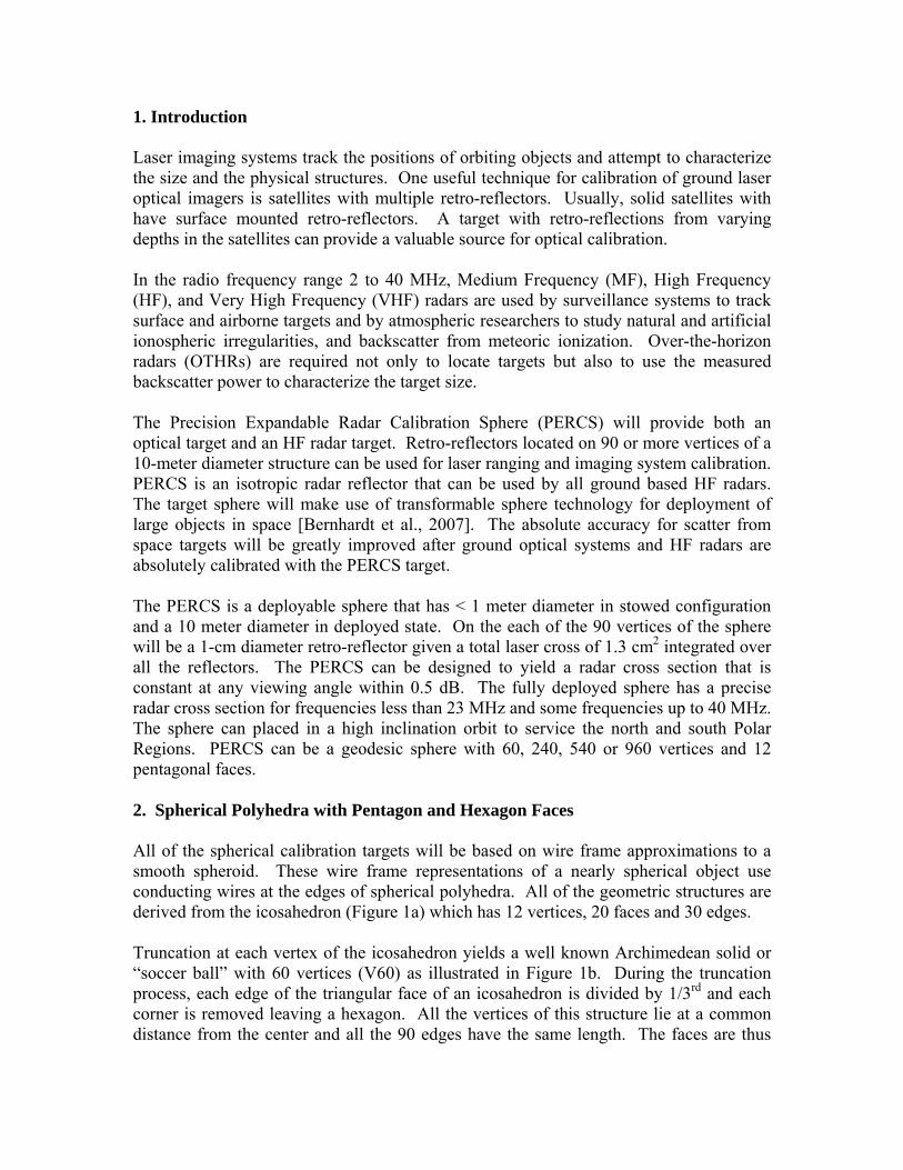
Figure 1. Geometric structures of potential radar calibration targets. The icosahedron (a) has each vertex truncated to yield a hexagonal face. The rest of the spherical surface is filled with hexagons to yield spherical polyhedra with (b) 60 vertices, (c) 240 vertices, (d) 540 vertices, and (e) 960 vertices. For simplicity of construction and reduction of atmospheric drag, the polyhedral surfaces shown in Figure 1 will be replaced by the wire frame targets of Figure 2. The targets are 10-meter in diameter with 60, 240, 540 and 960 vertices joined with conducting wires. The polygons on the geodesic structure are open so the wire frame has much lower drag than a similar design using a spheroid such as metalized balloon.
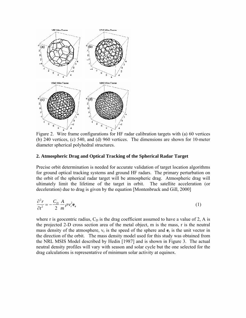
Figure 2. Wire frame configurations for HF radar calibration targets with (a) 60 vertices (b) 240 vertices, (c) 540, and (d) 960 vertices. The dimensions are shown for 10-meter diameter spherical polyhedral structures. 2. Atmospheric Drag and Optical Tracking of the Spherical Radar Target Precise orbit determination is needed for accurate validation of target location algorithms for ground optical tracking systems and ground HF radars. The primary perturbation on the orbit of the spherical radar target will be atmospheric drag. Atmospheric drag will ultimately limit the lifetime of the target in orbit. The satellite acceleration (or deceleration) due to drag is given by the equation [Montenbruck and Gill, 2000]
22
2 2D
rCr A v
t mρ∂
= −∂ re (1)
where r is geocentric radius, CD is the drag coefficient assumed to have a value of 2, A is the projected 2-D cross section area of the metal object, m is the mass, r is the neutral mass density of the atmosphere, vr is the speed of the sphere and er is the unit vector in the direction of the orbit. The mass density model used for this study was obtained from the NRL MSIS Model described by Hedin [1987] and is shown in Figure 3. The actual neutral density profiles will vary with season and solar cycle but the one selected for the drag calculations is representative of minimum solar activity at equinox.

Figure 3. Neutral density used for atmospheric drag calculations for the spherical radar target in space. Numerically integrating (3) for circular orbits yield a time history of the orbiting sphere. The mass and drag area for a fully metalized target with a 30 micron thick spherical shell is estimated to be 24 kg and 78 m2, respectively. Then this solid-surface spheroid is injected to orbit at 600 km, it will have a lifetime of only 40 days (see red line in Figure 4). For the V60 sphere made with 4 mm diameter arms, the spherical wire frame will remain in orbit for over 5 years (see blue line in Figure 4). For this model, the wire frame consists of gold plated aluminum struts with 4 cm thickness. The area to mass ration in (3) will be similar to the V60 for the higher order wire frames. Consequently, the orbit lifetime should be about 5 years. Even though the details of the orbit lifetime will vary with number of vertices and background neutral density, the wire frame has an obvious advantage a metal spherical balloon. The addition of corner cube reflectors to each vertex of the wire frame sphere permits laser satellite tracking of the radar target. Corner reflectors provide a reflection cross section for visible light that depends on the incident angle (Figure 5). With one corner cube on each vertex, those that are facing toward a ground laser system will reflect visible light back to the source (Figure 6). The total intensity of the reflected light will vary as the spherical target rotates. Using the V60 Wire-frame sphere and the tilt angle dependence on optical cross section, the fluctuations in total optical cross section were calculated for rotation around several axes on the sphere (Figure 7). The rotation rate for the target can be determined for the temporal fluctuations in the reflected light (Figure 7a and c). The lowest harmonic component of the frequency spectrum gives the rotation period (Figure 7b and d).

Figure 4. Neutral density imposed limitations on the lifetime of a 10-meter spherical radar target because of atmospheric drag. Laser satellite ranging sites can therefore provide both position and rotation information on the orbiting polyhedral sphere in space. This information can provide precise location of the target for HF radar calibration. Any small fluctuations in the optical scatter or HF radar return signal can be correlated with the independently measured rotation of the spherical target. The time dependent orientation of the PERCS sphere may be extracted from the temporal variations in the intensity of the laser reflections from the PERCS retro-reflectors. The differences in Figures 7 (a) and 7(c) illustrate the effects of tilt angle and rotation orientation of the total laser cross section. A single laser pulse will produce multiple time delayed pulses when the physical range to each laser reflector is considered. The time delay between laser pulse reflections will also provide information of the line-of-sight depth of the sphere. 3. Radar Cross Section of Spherical Polyhedra Monostatic radar cross section determines the amount of power reflected from an object back to the transmitter. The radar equation incorporates the radar cross section with transmitting system and receiving system parameters and range to the target
220 0r
2 2 2 4t
λ C (f, θ, )P G 1 σ = σ(f)P L (4π R ) 4π R
φ= (2)

where P is received (r) and transmitted (t) power, G is gain, L is loss, R is range, λ0 is wavelength, σ is radar cross section and C0 is the radar system parameter. The directional antenna gain G(f, θ, φ)for a ground radar system is dependent on the radar frequency (f), on the zenith angel to the target (θ) and the azimuth angle to the target (φ). The system losses L(f) are only frequency dependent. The cross section σ(f) of a spherical radar target is dependent on frequency but is independent of θ and φ. Measurements of the ratio Pr/Pt with a known σ over a range of look directions and frequencies permits estimation of the system parameter C0(f, θ, φ).
Figure 5. Laser light reflection cross section for a small corner cube reflector with less than 1 cm diameter. The estimations of RCS were obtained by applying the method of moments solutions to the electric field integral equations the using WIPL-D 3D Electromagnetic Solver [Kolundzija, et al., 2004]. The polyhedral wire frame is excited by a right-hand circular polarized (RHCP) electromagnetic wave. The incident and reflected waves are compared to yield the monostatic RCS. Radar scatter from the 60-vertex (V60) wire frame with 90 edges was examined in detail. The full range of RCS changes variations with radar observation direction is obtained by stepping the WIPL simulations through all target angles. The average value of RCS for all viewing angles is given in Figure 8. Between 9 and 33 MHz, the wire frame has a larger radar cross section than the spheroid with a continuous conducting surface.

Figure 6. Laser illumination of a V60 sphere with corner cube reflectors at each vertex.
Figure 7. Illustration of fluctuations in optical reflection cross section (a and c) and frequency spectra (b and d) as the spherical polyhedron rotates about an axis with tilts of 60 degrees (a and b) and 18 degrees (c and d), respectively. The maximum RCS deviation based on the WIPL computations shows that the 10-meter diameter V60 wire frame is well suited for a calibration target for frequencies less than

23 MHz where this deviation is less than 0.5 dB (Figure 9). Above 23 MHz, a local maximum in RCS variation with orientation is found to be 9.6 dB at 26 MHz. This makes the V60 of less useful in the 25 to 29 MHz band unless the orientation of the sphere is know. Figure 8, however, shows that that in the 30 to 34 MHz the variation in RCS with is at a minimum so that at this frequency the V60 conducting frame may be a useful radar calibration target.
Figure 8. Computed monostatic RCS averaged over all viewing directions.
Figure 9. Maximum variation in monostatic RCS for the V60 wire frame radar reflector. The useful radio frequency increases with the complexity of polyhedron sphere. Computations with the 240 vertex sphere (V240) have been reported by Bernhardt et al., [2007] 7. Summary

The Precise Expandable Radar Calibration Sphere (PERCS) has applications to programs at many organizations. Operators of space surveillance telescopes can use PERCS to check resolution. Algorithms for characterization of space objects may be validated with observations of the 10-meter diameter sphere with a well-defined structure. The Navy and Air Force manages the operational and development of both the relocatable over the horizon radar (ROTHR) and the High Frequency Active Auroral Research Program (HAARP). PERCS will provide the first long range calibration target for HF radars associated with these systems. All HF radars are affected by ionospheric refraction. The refraction effects are estimated using plasma density data from backscatter ionograms and other independent measurements. With radar scatter from the PERCS at a known location, the algorithms for target location will be tested and validated. Acknowledgments. This work was sponsored by the Office of Naval Research. References Bernhardt, P.A., C. L. Siefring, J. F. Thomason, S. P. Rodriquez, A. C. Nicholas, S. M. Koss, C. Hoberman, D. L. Hysell, The Design and Applications of A Versatile HF Radar Calibration Target in Low Earth Orbit, Radio Science (In Press) 1977. Hedin, A.E., MSIS-86 Thermospheric Model, J. Geophys. Res., 92, 4649, 1987. Koludzija, B., J. Oganjanovic, T. Sarkar, Miodrag Tasic, D. Olcan, B. Janic, D Sumic, WIPLE-D Software Users Manual, WIPL-D Ltd., Belgrade, 2004. Montenbruck, O. and E Gill, Satellite Orbits: Models, Methods and Applications, Springer, Berlin, 2000. Wang, B-C, and Y-N Chiu, Geometry and orbital symmetry relationships of gian and hyperfullerenes: C240, C540, C960, and C1500., Synthetic Metals, 55-57, 2949-2954, 1993.