cam followers...cam followers with roller cage and outer diameter from 16 to 90 mm • outer ring...
TRANSCRIPT

CAM FOLLOWERS

2 |

| 3
0SUMMARY
PAGE 4 1.0 THE NADELLA GROUP
PAGE 8 2.0 PRODUCT OVERVIEW
PAGE 18 3.0 PRODUCT DETAILS
PAGE 44 4.0 SPECIAL APPLICATIONS
PAGE 50 5.0 ACCESSORIES
PAGE 54 6.0 TECHNICAL SPECIFICATIONS
4 |
THE NADELLA GROUPTHE SPECIALIST FOR MOTION TECHNOLOGYNADELLA has grown and expanded continuously over the decades, moving from a simple supplier of needle roller bearings, parts for guide linear systems and industrial components, to expert and qualified partner capable of providing a full range of services and customisation in every sector linked to mechanical movement technology. Innovative ideas, precision and reliability are what make the companies in our Group stand out from the crowd.
CUSTOMISED SOLUTIONS
Our experts follow the projects developed with Nadella in the minutest detail, starting with the initial product development right up to delivery. Our internal procedures have, in fact, been developed in such a way as to guarantee quality and efficiency throughout the entire production process and all strictly within the company. Together with the standard processings found in the catalogue, special treatments on specific components are also available as well as rapid, express delivery. This applies to any kind of order or amount, including small and medium onex.
EXPERIENCE AND SKILLS
Production of customised parts and practical consulting are just some of our distinguishing features: our engineers follow our clients every step of the way and actively contribute to the development of their applications providing them with their skills, experience and technical knowledge of the industry. This often allows us to come up with special solutions that are so effective that they are adopted as new company standards.
MAXIMUM QUALITY AND CERTIFIED ENVIRONMENTAL MANAGEMENT
Excellent product quality and services have always been Nadella'stop priority. This is why each stage of the entire production process is regularly followed, controlled and scrupulously checked by our experts.
Furthermore, all the companies and plants that make up our Group have been certified in compliance with DIN EN ISO 9001.
In order to comply with these requirements and guarantee the top quality of our products over time, we make use of the latest instruments and test equipment available on the market, such as:
• CAQ System• CNC 3D Machinery• Force testing• Radiographic Inspection• Microsection analyses• Material tests on metal and plastic

| 5
1THE NADELLA GROUPTHE SPECIALIST FOR MOTION TECHNOLOGY

6 |
NUMEROUS ROADS LEAD TO NADELLABUT THEY ALL GET THERE QUICKLY, IRRESPECTIVE OF THE POINT OF DEPARTURE Our clients' satisfaction is at the heart of our success and growth. This is why we are here to serve you across the world and we always have your needs in mind.To date, we have a world network of distributors in all of the most important industrialised countries in Europe, Asia and the United Statex.This means we can guarantee client orientated consulting, delivery and service at any time.
BRANCHES AND DISTRIBUTORS
BelgiumBrazilDenmarkFinlandFranceEnglandIndiaKoreaThe NetherlandsNorwayAustriaPolandRomania
SwedenSwitzerlandSingaporeSlovakiaSloveniaSpainTaiwanCzech RepublicTurkeyHungary
GLOBAL NETWORKFOR AN IDEAL SERVICE
NADELLA'S KEY LOCATIONS ItalyGermanyChinaUnited States
DURBAL LOCATIONS Germany
CHIAVETTE UNIFICATE LOCATIONS Italy

| 7
8 |

| 9
PRODUCTOVERVIEW
PAGE 10 2.1 PRODUCT OVERVIEW
PAGE 11 2.2 INTRODUCTION TO CAM FOLLOWERS
PAGE 12 2.3 CAM FOLLOWERS WITH STUD GC ..MINICAM FOLLOWERS WITH STUD GC ..SW
PAGE 13 2.4 CAM FOLLOWERS WITH STUD KR ..EEFULL COMPLEMENT ROLLERS GCU
PAGE 14 2.5 SMALL CAM ROLLERS FPFULL COMPLEMENT NEEDLE ROLLERS FG..SW
PAGE 15 2.6 FULL COMPLEMENT ROLLERS FGUFULL COMPLEMENT NEEDLE ROLLERS RNA 11000
PAGE 16 2.7 CAM FOLLOWERS WITH PIVOT AND TAPERED BEARINGS PKGUIDE WHEELS FK
PAGE 17 2.8 CAM FOLLOWERS WITH HEAVY STUD PFLDOUBLE CAM FOLLOWERS WITH STUD PFDL
2

10 |
PRODUCTOVERVIEWCAM FOLLOWERS
Cam followers with stud GC ..MINI 20
Cam followers with stud GC ..SW 22
Cam followers with stud KR ..EE 24
Full complement rollers GCU 25
Small cam followers without stud FP 28
Full complement needle rollers FG..SW 30
Full complement rollers FGU light series 32
Full complement rollers FGU heavy series 34
Full complement needle rollers RNA 11000 36
Cam followers with pivot and tapered bearings PK 38
Tapered roller bearings FK 39
Cam followers with heavy stud PFL 40
Double cam followers with stud PFDL 42
2.1PAGE

| 11
2.2NADELLA cam followers are designed to rotate directly on cams, flat surfaces or guidex. In order to meet the unusual conditions of use - significant loads accompanied by substantial and repeated shocks - these types of bearings have the following characteristics:
• Heavy section outer ring, to support the load and minimise the risk of deformations that reduce the bearing's load-supporting capacity.
• Rolling or cup needle roller bearing, with cage or full complement to guarantee maximum load capacity.
• Outer profiled ring to compensate for parallelism errors between the roller and track or cylindrical ring to reduce contact pressure with the sliding surfacex.
• Lubrication hole with output under the needles to restore the grease through the axle.
CAMFOLLOWERS
The cam followers with stud can be equipped with an eccentric collar to adjust the pre-load during assembly.
The cam followers can be equipped with synthetic or metal seals to retain the grease.
Apart from the products shown in this catalogue, NADELLA produces numerous variants for specific operating conditions.

12 |
Full complement needle rollers with outer diameter up to 15mm • Convex (GC..) or cylindrical (GCL..) outer ring• Screwdriver slot head side to seal in position while blocking the nut The mini roller which thanks to the needle roller bearing has the highest load/diameter capacity ratio. See Page 20
Cam followers with stud GC.. MINI
2.3
Full complement needle rollers with outer diameter from 16 to 90 mm New SW version • Outer ring with optimised profile• Dimensions compliant with ISO 6278• More restrictive tolerances compared to ISO 7063• Built-in hexagonal socket on head side and stud side• Re-greasing on the head side, stud side and radial on the stud (see
tables for restrictions on small sizes)• Without seals, with plastic (suffix..EE) or metal (suffix...EEM) sliding
seals• With eccentric bearing (GCR..)
Cam followers with stud GC.. SW
This is the classic Nadella cam follower with stud updated with the extension of the adjustment hexagonal socket on each end and for all dimensions. The optimised profile on the outer diameter of the ring was also introduced (see pag. 59 for details) The full complement of needles guarantees full load capacity and rigidity the careful construction guarantee stricter tolerances compared to the ISO standard, with the tolerances on the outer diameter of the cam follower h6 (instead of h9 in ISO7063). See Page 22

| 13
2.4Cam followers with roller cage and outer diameter from 16 to 90 mm • Outer ring with convex profile • Re-greasing on the head side, stud side and radial on the stud (see
tables for restrictions on small sizes)• With axial drag yoke and plastic seal• With eccentric bearing (KRE..) The classic cam follower with cage. The need to re-lubricate the bearing, is reduced thanks to the cage and the axial drag yoke. This kind of bearing is suitable for less demanding applications but with elevated speed. See Page 24
Cam followers with stud KR.. EE
Full complement needle rollers with outer diameter from 35 to 130 mm • Dimensions compliant with ISO 6278• More restrictive tolerances compared to ISO 7063• Built-in hexagonal socket on head side and stud side• Re-greasing on the head side, stud side and radial on the stud • Without seals, or with metal seals (suffix...MM)• With eccentric bearing (GCUR..) This is the classic Nadella full complement roller updated with the extension of the adjustment hexagonal socket on both ends and for all dimensions.
Full complement rollers GCU
The assembly dimensions, for equivalent sizes, are the same as GC..SW. The roller solutions instead of the needles reduces the thickness of the outer ring and the number of rollers. The maximum load is reduced but the dynamic capacity of the cam follower without stud is increased. The larger dimensions, up to 130 mm, are the solution with the highest load capacity of all the cam followers with stud. See Page 25

14 |
2.5Full complement needle rollers with outer diameter from 10 mm to 15 mm • Convex (FP..) or cylindrical (FPL..) outer ring The mini roller which thanks to the needle roller bearing has the highest load/diameter capacity ratio. See Page 28
Mini cam followers without stud FP
Full complement needle rollers with outer diameter from 16 to 250 mm New SW version • Outer ring with optimised profile• Dimensions compliant with ISO 6278• More restrictive tolerances compared to ISO 7063• Without seals, with plastic (suffix..EE) or metal (suffix...EEM) sliding
seals The full complement of needle rollers guarantees full load capacity and rigidity. The unusual aspect of this cam roller without stud is the assembly of the axial yokes that are firmly fastened to the inner ring, as if it were one piece. See Page 30
Full complement needle rollers FG.. SW

| 15
2.6Full complement rollers with outer diameter from 35 to 300 mm. The heavy series differs from the light series in the thickness of the outer ring, from which a greater outer diameter derives and the ability to sustain more significant loads. • Dimensions compliant with ISO 6278• More restrictive tolerances compared to ISO 7063• Without seals, with metal guards (suffix...MM) The full complement rollers guarantee full load capacity and rigidity. The assembly dimensions, for equivalent sizes, are the same as GC..SW. The roller solutions instead of the needle followers reduces the thickness of the outer ring and the number of rolling elements. The maximum load is reduced but the dynamic capacity of the cam follower without stud is increased.
See Page 32 (light series) and Page 34 (heavy series)
Full complement rollers FGU
Ring with full complement of needle rollers, mechanically fastened and separate inner ring. Outer diameter from 19 to 90 mm
See Page 36
Full complement needle rollersRNA 11000

16 |
2.7Cam followers without stud with high load capacity and tapered roller bearings. Outer diameter from 52 to 110 mm • Version with eccentric stud PKR• Standard drag seal in NBR• Possibility of Viton seal for high temperature• Also available in stainless steel NX The tapered bearings absorb the axial thrusts due to the misalignments between the cam follower without stud and rolling track without compromising the function of the cam follower without stud. The width of the sleeve allows for the strain to be distributed on a wide contact surface with the rolling track. The amount of grease is sufficient for a life-long greasing of the cam follower without stud. The result is a robust, reliable component. See Page 38
Cam followers with pivot and tapered bearings PK
Cam followers without stud with high load capacity and tapered roller bearings. Outer diameter from 52 to 110 mm • Standard drag seal in NBR• Possibility of Viton seal for high temperature• Also available in stainless steel NX The tapered bearings absorb the axial thrusts due to the misalignments between the cam follower without stud and rolling track without compromising the function of the cam follower without stud. The width of the sleeve allows for the strain to be distributed on a wide contact surface with the rolling track. The amount of grease is sufficient for a life-long greasing of the cam follower without stud. The result is a robust, reliable component. See Page 39
Guide wheels FK

| 17
2.8Cam followers without stud with high precision and load capacity. Outer diameter of cam follower without stud from 10 to 22 mm Cam follower with heavy stud and careful construction for use on automatic machinery, positioners and cam movements. See Page 40
Cam followers with heavy stud PFL
For assembly on double contact cam movements. Outer diameter of cam follower without stud from 24 to 32 mm This is the ideal solution in the applications in which the cam is strained in alternating direction • Elimination of play between the cam and cam follower without stud in
the loading inversion points.• Elimination of the rotation inversion due to dragging and wear. See Page 42
Double cam followers with stud PFDL

18 |

| 19
PRODUCTDETAILS
PAGE 20 3.1 CAM FOLLOWERS WITH STUD GC ..MINI
PAGE 22 3.2 CAM FOLLOWERS WITH STUD GC ..SW
PAGE 24 3.3 CAM FOLLOWERS WITH STUD KR ..EE
PAGE 26 3.4 FULL COMPLEMENT ROLLERS GCU
PAGE 28 3.5 SMALL CAM ROLLERS FP
PAGE 30 3.6 FULL COMPLEMENT ROLLERS FG..SW
PAGE 32 3.7 COMBINED ROLLER FOLLOWERS FGU LIGHT SERIES
PAGE 34 3.8 COMBINED ROLLER FOLLOWERS FGU HEAVY SERIES
PAGE 36 3.9 FULL COMPLEMENT NEEDLE ROLLERS RNA 11000
PAGE 38 3.10 CAM FOLLOWERS WITH PIVOT AND TAPERED BEARINGS PK
PAGE 39 3.11 GUIDE WHEELS FK
PAGE 40 3.12 CAM FOLLOWERS WITH HEAVY STUD PFL
PAGE 42 3.13 DOUBLE CAM FOLLOWERS WITH STUD PFDL
3

20 |
CAM FOLLOWERS WITH STUDTYPE GC ..MINI 3.1Full complement needle rollers with outer diameter up to 15mm.
GC, GCL series without seal.
D
r
RC
d1
P
G
G1C1
dA
B2
L
B1
GC.. Mini
∅ outer D mm
Designation 1) d1 2)
mmLmm
B1
mmB2
mmThreading G mm
G1
mmCmm
C1
mmdA
mmrmm
R 3)
mmGC, GCL
10 10 4 19.5 8.5 11 M4x0.7 6 8 0.25 8.4 0.2 130
11 11 4 19.5 8.5 11 M4x0.7 6 8 0.25 8.4 0.2 130
12 12 5 22.5 9.5 13 M5x0.8 7 9 0.25 10.3 0.2 130
13 13 5 22.5 9.5 13 M5x0.8 7 9 0.25 10.3 0.2 130
14 14 6 26 10 16 M6x1 8 9 0.25 11.8 0.3 130
15 15 6 26 10 16 M6x1 8 9 0.25 11.8 0.3 130 1) Cam follower with stud designation GC.. Concentric cam follower with stud with convex outer ring GCL.. Concentric cam follower with stud with cylindrical outer ring2) Hole diameter for assembly d1 H73) Convex radius for GC version..

| 21
CAM FOLLOWERS WITH STUDGC ..MINI 3.1
Pmm
Load coefficients (N) Speed limit with grease (min-1)
WeightKg
Clamping torqueNm
∅ outer DmmCw Din. Fr Stat. For
6 2100 520 960 7500 0.006 0.9 10
6 2400 520 960 7400 0.007 0.9 11
5.4 2900 900 1700 6000 0.011 1.8 12
5.4 3200 900 1700 6000 0.011 1.8 13
6.4 3400 1500 2800 5500 0.016 3 14
6.4 3600 1500 2800 5500 0.018 3 15 The concentric cam followers with stud in the GC Mini series are supplied with two clamping nuts.

22 |
CAM FOLLOWERS WITH STUDTYPE GC .. SW 3.2Full complement needle rollers with outer diameter from 16 to 90 mm
Rp C P
B3
d1
r
D
W
B1
C1
dA
B2
L
G1
W
G
GC..SW
Foro 1 a partire da D=22 mmForo 2 a partire da D=30 mm
12
∅ outer Dmm
Designation 1)
d1 2)
mmLmm
B1
mmB2
mmThreading G mm
G1
mmCmm
C1
mmdA
mmB3
mmrmm
Rp 3)
mmGC .. SW
16 16 6 28,2 12,2 16,5 M6x1 8 11 0,6 13,3 0,3 500
19 19 8 32,2 12,2 20,5 M8x1.25 10 11 0,6 15,3 0,3 500
22 22 10 36,2 13,2 23,5 M10x1.25 12 12 0,6 18,2 0,3 600
24 24 10 36,2 13,2 23,5 M10x1.25 12 12 0,6 18,2 0,3 600
26 26 10 36,2 13,2 23,5 M10x1.25 12 12 0,6 20,8 0,3 600
28 28 10 36,2 13,2 23,5 M10x1.25 12 12 0,6 20,8 0,3 600
30 30 12 40,2 15,2 25,5 M12x1.5 13 14 0,6 24,8 6 0,6 700
32 32 12 40,2 15,2 25,5 M12x1.5 13 14 0,6 24,8 6 0,6 700
35 35 16 52,2 19,6 33 M16x1.5 17 18 0,8 28,8 8 0,6 800
40 40 18 58,1 21,6 37 M18x1.5 19 20 0,8 33,8 8 1 1000
47 47 20 66,1 25,6 41 M20x1.5 21 24 0,8 38,7 9 1 1200
52 52 20 66,1 25,6 41 M20x1.5 21 24 0,8 38,7 9 1 1200
62 62 24 80,1 30,6 50 M24x1.5 25 29 0,8 52 11 1 1500
72 72 24 80,1 30,6 50 M24x1.5 25 29 0,8 52 11 1 1500
80 80 30 100 37 63,5 M30x1.5 32 35 1 68 15 1 1700
85 85 9) 30 100 37 63,5 M30x1.5 32 35 1 68 15 1 1700
90 90 30 100 37 63,5 M30x1.5 32 35 1 68 15 1 1700
1) Cam follower with stud designation GC..SW Concentric cam follower with stud optimised profile outer ring GCL..SW Concentric cam follower with stud cylindrical outer ring (product available on request) GCR.. Cam follower with stud with eccentric collar No suffix Without seal Suffix ..EE With plastic seal, ex. GC40EESW Suffix ..EEM With metal seal, ex. GC40EEMSW2) Hole diameter for assembly of concentric cam follower without stud: d1 H73) Convex radius in the central part to contact pressure calculation
See page 47 for detailson stainless steel versions.
Bore hole 1 starting from D=22 mm
Bore hole 2 starting from D=30 mm

| 23
CAM FOLLOWERS WITH STUDTYPE GC .. SW 3.2
Rp C P
B3
d1
r
D
W
B1
C1
dA
B2
L
G1
W
G
GC..SW
Foro 1 a partire da D=22 mmForo 2 a partire da D=30 mm
12
Be Pe
kde
4 Be Pe
k
de M
da GCR16SW a GCR52SW da GCR62SW a GCR90SW
Wmm
P 7)
mm
Eccentric bearing Load coefficients (N) 6)
Greasing speed limitwith grease (min-1)
Weight of nut and washers Kg
Clamping torque Nm
∅ outer Dmmde 4) 5)
mmk 5)
mmM 5)
mmBe 5)
mmPe 8)
mmCw Din. Fr Stat. For
4 6,4 9 0,5 8 5,6 4900 1200 2300 5000 0,024 3 16
4 8 11 0,5 10 6,4 5600 2900 5400 4100 0,039 8 19
4 10 14 1 11 7,9 6900 5300 9400 3400 0,057 20 22
4 10 14 1 11 7,9 7600 5300 9800 3400 0,072 20 24
4 10 14 1 11 7,9 8600 5300 9800 3000 0,08 20 26
4 10 14 1 11 7,9 9200 5300 9800 3000 0,088 20 28
6 12 16 1 11 9,5 13000 7900 15000 2600 0,118 26 30
6 12 16 1 11 9,5 13000 7900 15000 2600 0,126 26 32
10 16 21 1,5 14 12,2 18000 14000 23000 2100 0,22 64 35
12 18 24 1,5 16 13,4 22000 19000 34000 1800 0,321 90 40
14 20 27 2 17,5 14,4 27000 22000 35000 1500 0,5 120 47
14 20 27 2 17,5 14,4 33000 22000 40000 1500 0,568 120 52
12 24 36 3 44 18 17,5 42000 31000 58000 1200 1,035 220 62
12 24 36 3 44 18 17,5 46000 31000 58000 1200 1,278 220 72
14 30 42 3 50 27 20,6 58000 50000 93000 900 2,074 450 80
14 30 42 3 50 27 20,6 61000 50000 93000 900 2,235 450 85
14 30 42 3 50 27 20,6 63000 50000 93000 900 2,435 450 90 4) Hole diameter for assembly of the eccentric cam follower without stud: de H75) Dimensions of the eccentric bearing.6) Fr and For load for cam follower without stud, with no eccentric collar.7) The GC concentric cam followers with stud are supplied with two clamping nuts.8) GCR eccentric cam followers with stud are supplied with eccentric bearing already fitted, clamping nut, cogged washer and support surface washer.9) Product available on request
See page 47 for detailson stainless steel versions.
from GCR16SW to GCR52SW from GCR62SW to GCR90SW

24 |
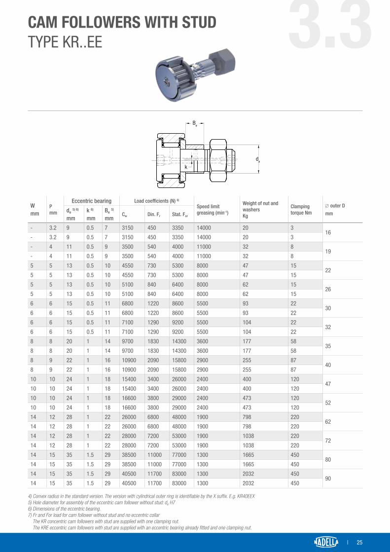
CAM FOLLOWERS WITH STUDTYPE KR..EE 3.3Cam followers with stud, with roller cage and outer diameter from 16 to 90 mm
D
W
R
r
C
B1
C1
LB2
G1
dA
W
G
d1
B3
P
12
Foro 1 a partire da D=22 mmForo 2 a partire da D=30 mm
∅ outer Dmm
Designation 1)
d1 2)
mmLmm
B1
mmB2
mmThreading G mm
G1
mmCmm
C1
mmdA
mmB3
mmrmm
R 4)
mmKR, KR..EE
16KR16 3) 6 28 12.2 16 M6x1 8 11 0.6 12.5 - 0.15 500
KR16EE 3) 6 28 12.2 16 M6x1 8 11 0.6 12.5 - 0.15 500
19KR19 3) 8 32 12.2 20 M8x1.25 10 11 0.6 15 - 0.15 500
KR19EE 3) 8 32 12.2 20 M8x1.25 10 11 0.6 15 - 0.15 500
22KR22 10 36 13.2 23 M10x1 12 12 0.6 17.5 - 0.3 500
KR22EE 10 36 13.2 23 M10x1 12 12 0.6 17.5 - 0.3 500
26KR26 10 36 13.2 23 M10x1 12 12 0.6 17.5 - 0.3 500
KR26EE 10 36 13.2 23 M10x1 12 12 0.6 17.5 - 0.3 500
30KR30 12 40 15.2 25 M12x1.5 13 14 0.6 23 6 0.6 500
KR30EE 12 40 15.2 25 M12x1.5 13 14 0.6 23 6 0.6 500
32KR32 12 40 15.2 25 M12x1.5 13 14 0.6 23 6 0.6 500
KR32EE 12 40 15.2 25 M12x1.5 13 14 0.6 23 6 0.6 500
35KR35 16 52 19.6 32.5 M16x1.5 17 18 0.8 27.6 8 0.6 500
KR35EE 16 52 19.6 32.5 M16x1.5 17 18 0.8 27.6 8 0.6 500
40KR40 18 58 21.6 36.5 M18x1.5 19 20 0.8 31.5 8 1 500
KR40EE 18 58 21.6 36.5 M18x1.5 19 20 0.8 31.5 8 1 500
47KR47 20 66 25.6 40.5 M20x1.5 21 24 0.8 36.5 9 1 500
KR47EE 20 66 25.6 40.5 M20x1.5 21 24 0.8 36.5 9 1 500
52KR52 20 66 25.6 40.5 M20x1.5 21 24 0.8 36.5 9 1 500
KR52EE 20 66 25.6 40.5 M20x1.5 21 24 0.8 36.5 9 1 500
62KR62 24 80 30.6 49.5 M24x1.5 25 29 0.8 44 11 1 500
KR62EE 24 80 30.6 49.5 M24x1.5 25 29 0.8 44 11 1 500
72KR72 24 80 30.6 49.5 M24x1.5 25 29 0.8 44 11 1.1 500
KR72EE 24 80 30.6 49.5 M24x1.5 25 29 0.8 44 11 1.1 500
80KR80 30 100 37 63 M30x1.5 32 35 1 53 15 1.1 500
KR80EE 30 100 37 63 M30x1.5 32 35 1 53 15 1.1 500
90KR90 30 100 37 63 M30x1.5 32 35 1 53 15 1.1 500
KR90EE 30 100 37 63 M30x1.5 32 35 1 53 15 1.1 500
1) Cam follower with stud designation KR.. Cam follower with stud, with no seals, KR..EE Cam follower with stud with axial drag discs and seals, KRE.. Cam follower with stud with no seals, with eccentric collar, KRE.. EE Cam follower with stud with axial drag discs and seals and with eccentric collar.2) Hole diameter for assembly of concentric cam follower without stud: d1 H73) For 16 and 19 mm diameter the standard cam followers with stud on the head side are supplied with screwdriver slot and grease nipple. The version with built-in hexagonal socket and no grease nipple is identifiable by the SK suffix
Bore hole 1 starting from D=22 mm
Bore hole 2 starting from D=30 mm
| 25
CAM FOLLOWERS WITH STUDTYPE KR..EE 3.3
Be
de
k
Wmm
Pmm
Eccentric bearing Load coefficients (N) 6)
Speed limitgreasing (min-1)
Weight of nut and washers Kg
Clamping torque Nm
∅ outer Dmmde 5) 6)
mmk 6)
mmBe 5)
mmCw Din. Fr Stat. For
- 3.2 9 0.5 7 3150 450 3350 14000 20 316
- 3.2 9 0.5 7 3150 450 3350 14000 20 3
- 4 11 0.5 9 3500 540 4000 11000 32 819
- 4 11 0.5 9 3500 540 4000 11000 32 8
5 5 13 0.5 10 4550 730 5300 8000 47 1522
5 5 13 0.5 10 4550 730 5300 8000 47 15
5 5 13 0.5 10 5100 840 6400 8000 62 1526
5 5 13 0.5 10 5100 840 6400 8000 62 15
6 6 15 0.5 11 6800 1220 8600 5500 93 2230
6 6 15 0.5 11 6800 1220 8600 5500 93 22
6 6 15 0.5 11 7100 1290 9200 5500 104 2232
6 6 15 0.5 11 7100 1290 9200 5500 104 22
8 8 20 1 14 9700 1830 14300 3600 177 5835
8 8 20 1 14 9700 1830 14300 3600 177 58
8 9 22 1 16 10900 2090 15800 2900 255 8740
8 9 22 1 16 10900 2090 15800 2900 255 87
10 10 24 1 18 15400 3400 26000 2400 400 12047
10 10 24 1 18 15400 3400 26000 2400 400 120
10 10 24 1 18 16600 3800 29000 2400 473 12052
10 10 24 1 18 16600 3800 29000 2400 473 120
14 12 28 1 22 26000 6800 48000 1900 798 22062
14 12 28 1 22 26000 6800 48000 1900 798 220
14 12 28 1 22 28000 7200 53000 1900 1038 22072
14 12 28 1 22 28000 7200 53000 1900 1038 220
14 15 35 1.5 29 38500 11000 77000 1300 1665 45080
14 15 35 1.5 29 38500 11000 77000 1300 1665 450
14 15 35 1.5 29 40500 11700 83000 1300 2032 45090
14 15 35 1.5 29 40500 11700 83000 1300 2032 450 4) Convex radius in the standard version. The version with cylindrical outer ring is identifiable by the X suffix. E.g. KR40EEX 5) Hole diameter for assembly of the eccentric cam follower without stud: de H76) Dimensions of the eccentric bearing.7) Fr and For load for cam follower without stud and no eccentric collar The KR concentric cam followers with stud are supplied with one clamping nut. The KRE eccentric cam followers with stud are supplied with an eccentric bearing already fitted and one clamping nut.

26 |
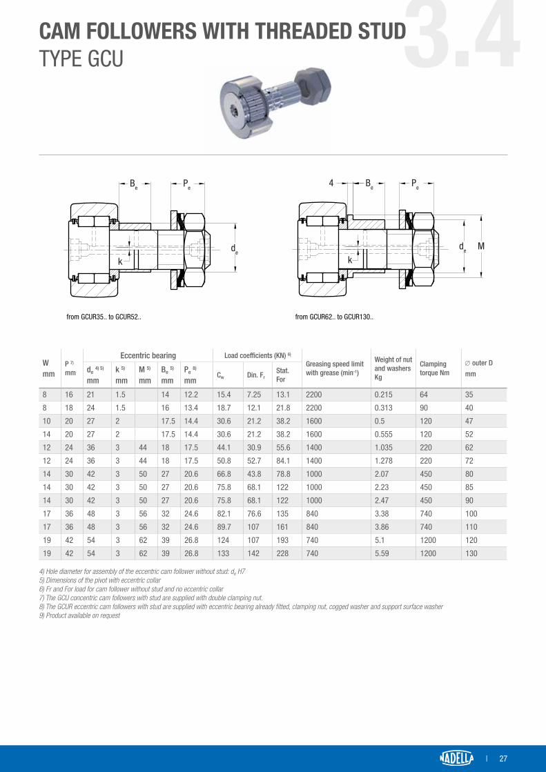
CAM FOLLOWERS WITH THREADED STUDTYPE GCU 3.4Full complement needle followerswith outer diameter from 35 to 130 mm
D
W
R
r
CB3
d1
P
G
WG1
dA
B2
C1
B1
LGCU..
∅ outer Dmm
Designation 1)
d1 2)
mmLmm
B1
mmB2
mmThreading G mm
G1
mmCmm
C1
mmdA
mmB3
mmrmm
R 3)
mmGCU,GCU..MM
35 35 16 52.5 19.7 32.8 M16x1.5 17 18 0.85 26 8 0.6 320
40 40 18 58.5 21.7 36.8 M18x1.5 19 20 0.85 28.6 8 1 400
47 47 20 66.5 25.7 40.8 M20x1.5 21 24 0.85 33.6 9 1 500
52 52 20 66.5 25.7 40.8 M20x1.5 21 24 0.85 33.6 9 1 500
62 62 24 80.5 30.7 49.8 M24x1.5 25 29 0.85 38.9 11 1 640
72 72 24 80.5 30.7 49.8 M24x1.5 25 29 0.85 38.9 11 1.1 640
80 80 30 100.5 37.2 63.3 M30x1.5 32 35 1.1 51.8 15 1.1 800
85 85 9) 30 100.5 37.2 63.3 M30x1.5 32 35 1.1 51.8 15 1.1 800
90 90 30 100.5 37.2 63.3 M30x1.5 32 35 1.1 51.8 15 1.1 800
100 100 36 117.5 42.2 75.3 M36x3 38 40 1.1 61 20 2 1000
110 110 36 117.5 42.2 75.3 M36x3 38 40 1.1 61 20 2 1000
120 120 42 136.5 48.2 88.3 M42x3 44 46 1.1 71 24 2 1200
130 130 42 136.5 48.2 88.3 M42x3 44 46 1.1 71 24 2 1200
1) Cam follower with stud designation GCU.. Concentric cam follower with stud and convex outer ring GCUL.. Concentric cam follower with stud and cylindrical outer ring GCUR.. Eccentric cam follower with stud and convex outer ring GCURL.. Eccentric cam follower with stud and cylindrical outer ring No suffix Without guards Suffix..MM With metal guards 2) Hole diameter for assembly of concentric cam follower without stud: d1 H7 3) Convex radius in the standard version GCU.
| 27
CAM FOLLOWERS WITH THREADED STUDTYPE GCU 3.4
Be Pe
kde
da GCUR35.. a GCUR52..
4 Be Pe
kde M
da GCUR62.. a GCUR130..
Wmm
P 7)
mm
Eccentric bearing Load coefficients (KN) 6)
Greasing speed limitwith grease (min-1)
Weight of nut and washers Kg
Clamping torque Nm
∅ outer Dmmde 4) 5)
mmk 5)
mmM 5)
mmBe 5)
mmPe 8)
mmCw Din. Fr
Stat. For
8 16 21 1.5 14 12.2 15.4 7.25 13.1 2200 0.215 64 35
8 18 24 1.5 16 13.4 18.7 12.1 21.8 2200 0.313 90 40
10 20 27 2 17.5 14.4 30.6 21.2 38.2 1600 0.5 120 47
14 20 27 2 17.5 14.4 30.6 21.2 38.2 1600 0.555 120 52
12 24 36 3 44 18 17.5 44.1 30.9 55.6 1400 1.035 220 62
12 24 36 3 44 18 17.5 50.8 52.7 84.1 1400 1.278 220 72
14 30 42 3 50 27 20.6 66.8 43.8 78.8 1000 2.07 450 80
14 30 42 3 50 27 20.6 75.8 68.1 122 1000 2.23 450 85
14 30 42 3 50 27 20.6 75.8 68.1 122 1000 2.47 450 90
17 36 48 3 56 32 24.6 82.1 76.6 135 840 3.38 740 100
17 36 48 3 56 32 24.6 89.7 107 161 840 3.86 740 110
19 42 54 3 62 39 26.8 124 107 193 740 5.1 1200 120
19 42 54 3 62 39 26.8 133 142 228 740 5.59 1200 130 4) Hole diameter for assembly of the eccentric cam follower without stud: de H75) Dimensions of the pivot with eccentric collar6) Fr and For load for cam follower without stud and no eccentric collar7) The GCU concentric cam followers with stud are supplied with double clamping nut.8) The GCUR eccentric cam followers with stud are supplied with eccentric bearing already fitted, clamping nut, cogged washer and support surface washer9) Product available on request
Be Pe
kde
da GCUR35.. a GCUR52..
4 Be Pe
kde M
da GCUR62.. a GCUR130..from GCUR62.. to GCUR130..from GCUR35.. to GCUR52..

28 |
SMALL CAM ROLLERS WITHOUT STUDFP 3.5Full complement needle followerswith outer diameter from 10 to 15mm
Dr1
r
RC
B
d dA
∅ outer Dmm
Designation 1) d 2)
mmBmm
Cmm
dA
mmrmm
r1
mmR 3)
mmFP, FPL
10 3 10 3 8.7 8 8.5 0.2 0.15 130
11 3 11 4) 3 8.7 8 8.5 0.2 0.15 130
12 4 12 4 9.7 9 9.9 0.2 0.15 130
13 4 13 4) 4 9.7 9 9.9 0.2 0.15 130
14 4 14 4) 4 10.2 9 11.8 0.3 0.15 130
15 4 15 4 10.2 9 11.8 0.3 0.15 130
1) Designation FP outer convex ring FPL outer cylindrical ring2) Diameter of the pivot to insert in the recommended hole: h53) Version FP convex radius4) Product available on request

| 29
SMALL CAM ROLLERS WITHOUT STUDFP 3.5
Load coefficients (N) Grease speed limit(min-1)
WeightKgCw Din Fr Stat. For
2200 2200 2200 8200 0.004
2300 2300 2300 8200 0.005
3100 3500 3500 6800 0.006
3200 3800 3800 6800 0.008
3300 3900 3900 6800 0.010
3300 3900 3900 6800 0.011

30 |
FULL COMPLEMENT NEEDLE ROLLERSFG ..SW 3.6Full complement needle followerswith outer diameter from 16 to 270 mm
CRp
r
D d
r1
D1 dA
B
∅ outer Dmm
Designation 1)d 2)
mmBmm
Cmm
D1
mmdA
3) mm
rmm
r1
mmRp
4)
mmFG ..SW
16 5 16 5 12 11 7,1 10,4 0,3 0,3 500
19 6 19 6 12 11 8,1 12,6 0,3 0,3 500
248 24 8 13 12 10,8 15,5 0,3 0,3 600
8 24 15 8 15 14 10,8 15,5 0,3 0,3 600
30 10 30 10 15 14 13,8 22 0,6 0,3 700
32 12 32 12 15 14 14,6 22 0,6 0,3 700
35 15 35 15 19 18 18,7 26 0,6 0,3 800
40 17 40 17 21 20 21,1 31 0,6 0,3 1000
47 20 47 20 25 24 25,7 35 1 0,3 1200
52 25 52 25 25 24 29,5 35 1 0,3 1200
62 30 62 30 29 28 34,8 45 1 0,3 1500
72 35 72 35 29 28 39,9 45 1 0,6 1500
80 40 80 40 32 30 46,6 61,1 1 0,6 1700
85 45 85 5) 45 32 30 51 61,1 1 0,6 1700
90 50 90 50 32 30 59 71 1 0,6 1700
100 55 100 55 36 34 61,3 71 1,5 0,6 2000
110 60 110 60 36 34 67 77 1,5 0,6 2000
120 65 120 65 42 40 74 83 1,5 0,6 2500
125 70 125 5) 70 42 40 80 91 1,5 0,6 2500
130 75 130 5) 75 42 40 82 94 1,5 0,6 2500
140 80 140 80 48 46 87 100 2 1 2800
150 85 150 5) 85 48 46 94 105 2 1 2800
160 90 160 5) 90 54 52 100,9 115 2 1 3000
170 95 170 95 54 52 107 120 2 1 3000
180 100 180 100 65 63 112 128 2 1,5 4000
200 110 200 5) 110 65 63 122,5 138 2 1,5 4000
215 120 215 5) 120 65 63 130,1 145 2 1,5 4000
230 130 230 5) 130 78 75 150 168 3 1,5 4500
250 140 250 5) 140 78 75 162 183 3 1,5 4500
270 150 270 5) 150 78 75 168 188 3 1,5 4500

| 31
FULL COMPLEMENT NEEDLE ROLLERSFG ..SW 3.6
Load coefficients (N) Speed limitgreasing (min-1)
WeightKg
Designation FG ..SWCw Din Fr Stat. For
4900 4900 5300 5000 0,016 5 16
5600 5800 6600 4100 0,019 6 19
7600 10000 10000 3400 0,037 8 24
9200 13000 13000 3400 0,044 8 24 15
13000 12000 15000 2600 0,066 10 30
12000 17000 18000 2500 0,077 12 32
17000 15000 24000 2000 0,103 15 35
22000 21000 34000 1800 0,155 17 40
27000 22000 35000 1500 0,295 20 47
29000 33000 54000 1400 0,31 25 52
38000 43000 69000 1100 0,49 30 62
43000 56000 87000 1000 0,67 35 72
52000 66000 110000 870 0,89 40 80
54000 68000 110000 810 0,97 45 85 5)
49000 57000 93000 710 1,04 50 90
66000 100000 150000 670 1,35 55 100
71000 120000 170000 620 1,65 60 110
81000 140000 210000 560 2,35 65 120
84000 140000 220000 530 2,5 70 125 5)
84000 140000 220000 510 2,65 75 130 5)
110000 190000 280000 480 3,4 80 140
110000 200000 300000 440 4 85 150 5)
130000 320000 340000 420 5,3 90 160 5)
130000 250000 390000 390 6 95 170
180000 280000 460000 360 8,05 100 180
200000 380000 550000 340 10 110 200 5)
220000 460000 620000 320 11,5 120 215 5)
250000 340000 560000 280 15,5 130 230 5)
280000 410000 670000 260 18,5 140 250 5)
300000 540000 860000 250 22 150 270 5)
1) Cam follower without stud designation FG..SW Cam follower without stud with optimised outer profile ring without seal Suffix..EE With plastic seals available up to outer diameter of 90 mm e.g. FG40EESW Suffix ..EEM With metal seals e.g. FG40EEMSW FGL..SW Cam follower with cylindrical outer ring
2) Recommended diameter for pivot: h5
3) Minimum recommended abutment support diameter in the event of excessive axial load or if there are vibrations
4) Convex radius in the central part to contact pressure calculation
5) Product available on request
32 |
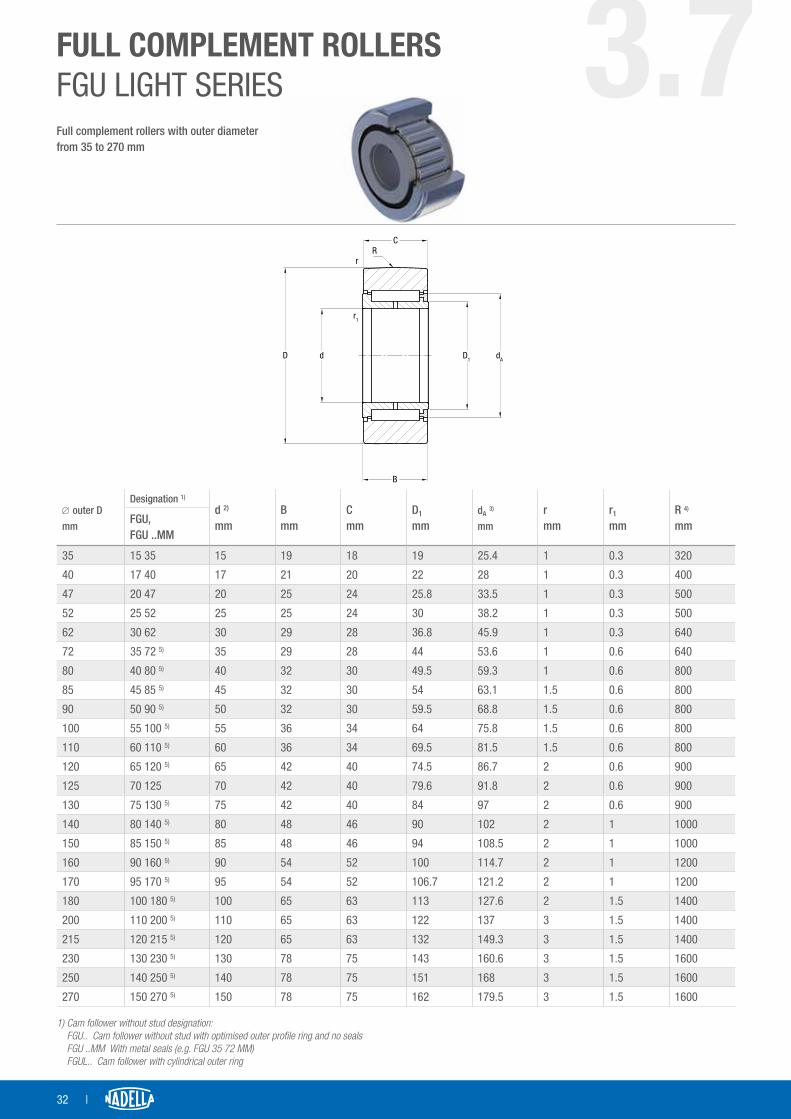
FULL COMPLEMENT ROLLERSFGU LIGHT SERIES 3.7Full complement rollers with outer diameter from 35 to 270 mm
D d
r1
rR
C
D1 dA
B
∅ outer Dmm
Designation 1)
d 2)
mmBmm
Cmm
D1
mmdA 3) mm
rmm
r1
mmR 4)
mmFGU,FGU ..MM
35 15 35 15 19 18 19 25.4 1 0.3 320
40 17 40 17 21 20 22 28 1 0.3 400
47 20 47 20 25 24 25.8 33.5 1 0.3 500
52 25 52 25 25 24 30 38.2 1 0.3 500
62 30 62 30 29 28 36.8 45.9 1 0.3 640
72 35 72 5) 35 29 28 44 53.6 1 0.6 640
80 40 80 5) 40 32 30 49.5 59.3 1 0.6 800
85 45 85 5) 45 32 30 54 63.1 1.5 0.6 800
90 50 90 5) 50 32 30 59.5 68.8 1.5 0.6 800
100 55 100 5) 55 36 34 64 75.8 1.5 0.6 800
110 60 110 5) 60 36 34 69.5 81.5 1.5 0.6 800
120 65 120 5) 65 42 40 74.5 86.7 2 0.6 900
125 70 125 70 42 40 79.6 91.8 2 0.6 900
130 75 130 5) 75 42 40 84 97 2 0.6 900
140 80 140 5) 80 48 46 90 102 2 1 1000
150 85 150 5) 85 48 46 94 108.5 2 1 1000
160 90 160 5) 90 54 52 100 114.7 2 1 1200
170 95 170 5) 95 54 52 106.7 121.2 2 1 1200
180 100 180 5) 100 65 63 113 127.6 2 1.5 1400
200 110 200 5) 110 65 63 122 137 3 1.5 1400
215 120 215 5) 120 65 63 132 149.3 3 1.5 1400
230 130 230 5) 130 78 75 143 160.6 3 1.5 1600
250 140 250 5) 140 78 75 151 168 3 1.5 1600
270 150 270 5) 150 78 75 162 179.5 3 1.5 1600
1) Cam follower without stud designation: FGU.. Cam follower without stud with optimised outer profile ring and no seals FGU ..MM With metal seals (e.g. FGU 35 72 MM) FGUL.. Cam follower with cylindrical outer ring

| 33
FULL COMPLEMENT ROLLERSFGU LIGHT SERIES 3.7
Load coefficients (N)Speed limitgreasing (min-1)
WeightKg
Designation 1)
FGU,FGU ..MMCw Din. Fr Stat. For
15000 8100 13000 2200 0.099 15 35
19000 15000 21000 2000 0.142 17 40
28000 25000 30000 1800 0.239 20 47
27000 17000 28000 1500 0.276 25 52
41000 22000 36000 1200 0.461 30 62
52000 46000 67000 1100 0.629 35 72 5)
59000 50000 72000 1000 0.831 40 80 5)
59000 38000 62000 890 0.895 45 85 5)
61000 38000 62000 830 0.963 50 90 5)
72000 37000 60000 730 1.35 55 100 5)
90000 70000 110000 700 1.672 60 110 5)
110000 89000 140000 640 2.364 65 120 5)
110000 84000 140000 600 2.48 70 125
110000 79000 130000 670 2.611 75 130 5)
140000 120000 190000 540 3.52 80 140 5)
140000 130000 200000 500 4.077 85 150 5)
180000 160000 260000 480 5.227 90 160 5)
190000 180000 290000 460 5.943 95 170 5)
240000 240000 390000 430 8.178 100 180 5)
260000 290000 470000 390 10.343 110 200 5)
280000 320000 510000 370 11.782 120 215 5)
350000 340000 550000 340 15.859 130 230 5)
380000 400000 650000 310 19.034 140 250 5)
430000 590000 810000 310 20.014 150 270 5)
2) Recommended diameter for pivot: h53) Minimum recommended abutment support diameter in the event of excessive axial load or if there are vibrations4) Convex radius in the central part to contact pressure calculation5) Product available on request

34 |
FULL COMPLEMENT ROLLERSFGU HEAVY SERIES 3.8Full complement rollers with outer diameter from 42 to 320 mm.
∅ outer Dmm
Designation 1)
d 2)
mmBmm
Cmm
D1
mmdA 3) mm
rmm
r1
mmR 4)
mmFGU,FGU ..MM
42 15 42 15 19 18 19 25.4 1 0.3 320
47 17 47 17 21 20 22 28 1 0.3 400
52 20 52 20 25 24 25.8 33.5 1 0.3 500
62 25 62 25 25 24 30 38.2 1 0.3 500
72 30 72 30 29 28 36.8 45.9 1 0.3 640
80 35 80 35 29 28 44 53.6 1 0.6 640
90 40 90 5) 40 32 30 49.5 59.3 1 0.6 800
100 45 100 45 32 30 54 63.1 1.5 0.6 800
110 50 110 50 32 30 59.5 68.8 1.5 0.6 800
120 55 120 55 36 34 64 75.8 1.5 0.6 800
130 60 130 60 36 34 69.5 81.5 1.5 0.6 800
140 65 140 65 42 40 74.5 86.7 2 0.6 900
150 70 150 70 42 40 79.6 91.8 2 0.6 900
160 75 160 5) 75 42 40 84 97 2 0.6 900
170 80 170 80 48 46 90 102 2 1 1000
180 85 180 5) 85 48 46 94 108.5 2 1 1000
190 90 190 5) 90 54 52 100 114.7 2 1 1200
200 95 200 95 54 52 106.7 121.2 2 1 1200
215 100 215 100 65 63 113 127.6 2 1.5 1400
240 110 240 5) 110 65 63 122 137 3 1.5 1400
260 120 260 5) 120 65 63 132 149.3 3 1.5 1400
280 130 280 5) 130 78 75 143 160.6 3 1.5 1600
300 140 300 140 78 75 151 168 3 1.5 1600
320 150 320 5) 150 78 75 162 179.5 3 1.5 1600
1) Cam follower without stud designation FGU.. Cam follower without stud with optimised outer profile ring and no seals FGU ..MM With metal seals e.g. FGU 35 80 MM FGUL.. Cam follower without stud with cylindrical outer ring
D d
r1
rR
C
D1 dA
B

| 35
FULL COMPLEMENT ROLLERSFGU HEAVY SERIES 3.8
Load coefficients (N)Speed limitgreasing (min-1)
WeightKg
Designation 1)
FGU,FGU ..MMCw Din Fr Stat. For
23000 26000 26000 2200 0.16 15 42
25000 30000 30000 2000 0.22 17 47
34000 40000 40000 1800 0.31 20 52
39000 50000 50000 1500 0.45 25 62
58000 70000 76000 1200 0.7 30 72
64000 88000 88000 1100 0.73 35 80
74000 98000 98000 1000 1.13 40 90 5)
83000 120000 120000 890 1.4 45 100
90000 130000 130000 830 1.7 50 110
110000 150000 160000 730 2.27 55 120
120000 180000 180000 700 2.68 60 130
140000 220000 220000 640 3.6 65 140
150000 240000 240000 600 4.17 70 150
150000 260000 260000 570 4.75 75 160 5)
180000 330000 330000 540 6.16 80 170
190000 350000 350000 500 6.87 85 180 5)
240000 400000 400000 480 8.57 90 190 5)
250000 420000 420000 460 9.5 95 200
310000 570000 570000 430 13.54 100 215
330000 630000 630000 390 13.95 110 240 5)
350000 670000 670000 370 21.19 120 260 5)
460000 860000 860000 340 27.63 130 280 5)
480000 910000 910000 310 31.73 140 300
500000 930000 930000 310 35.97 150 320 5)
2) Recommended diameter for pivot: h53) Minimum recommended abutment support diameter in the event of excessive axial load or if there are vibrations4) Convex radius in the central part to contact pressure calculation5) Product available on request

36 |
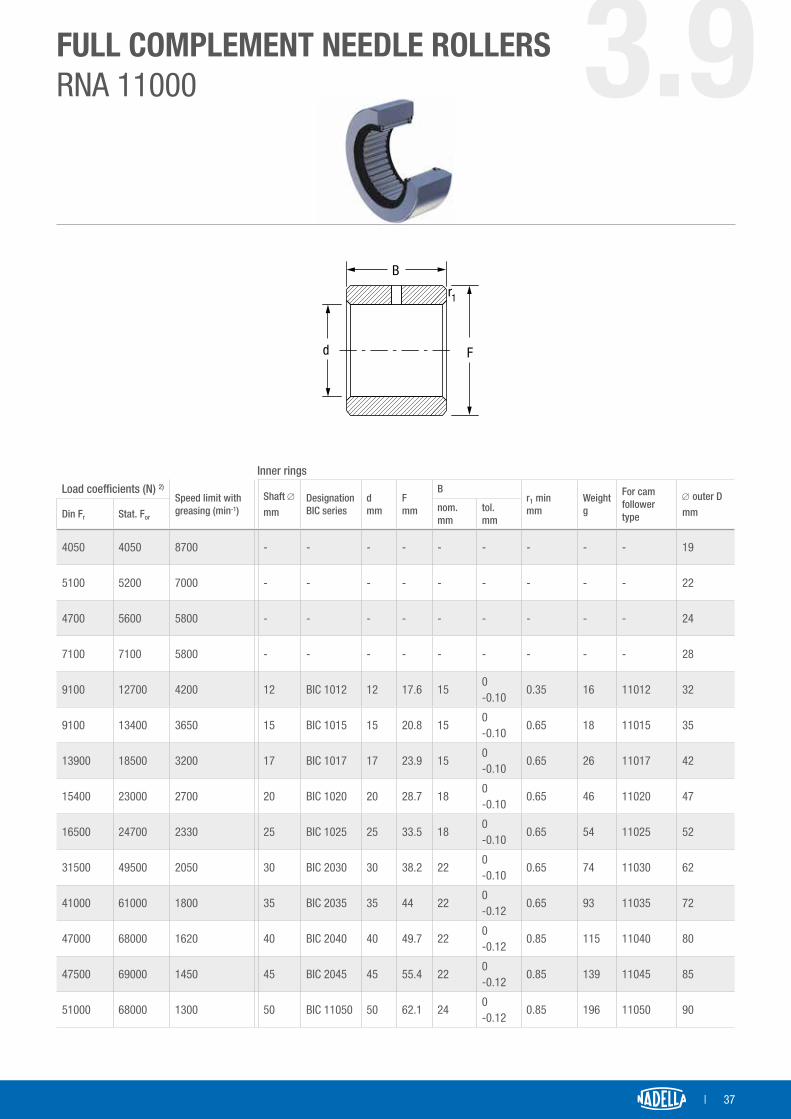
FULL COMPLEMENT NEEDLE ROLLERSRNA 11000 3.9Ring with full complement needle rollers, mechanically fastened and separate inner ring.Outer diameter from 19 to 90 mm
DE w Fw
rC
B
Fd
r1
∅ outer Dmm
DesignationFw 2)
mmD 1)
mm
CEW mm
r min.mm
Weightg
Load coefficients (N) 2)
RNA ..B6 nom.mm
tol.mm Cw
19 11005 B6 7.3 19 120-0.10
7.3 0.35 19 5100
22 11007 B6 9.7 22 120-0.10
14.7 0,35 25 6000
24 14601 B6 12.1 24 120-0.10
17.1 0.35 27 6200
28 11009 B6 12.1 28 12-0.20-0.30
17.1 0.35 42 7400
32 11012 B6 17.6 32 15-0.20-0.30
22.6 0.35 57 10800
35 11015 B6 20.8 35 15-0.20-0.30
25.8 0.65 62 10800
42 11017 B6 23.9 42 15-0.20-0.30
28.9 0.65 98 13400
47 11020 B6 28.7 47 18-0.20-0.30
34.7 0.65 133 16800
52 11025 B6 33.5 52 18-0.20-0.30
39.5 0.65 152 17200
62 11030 B6 38.2 62 22-0.20-0.30
44.2 0.65 275 28500
72 11035 B6 44 72 22-0.22-0.34
50 0.65 370 32000
80 11040 B6 49.7 80 22-0.22-0.34
55.7 0.85 450 34000
85 11045 B6 55.4 85 22-0.22-0.34
62.4 0.85 480 33500
90 11050 B6 62.1 90 24-0.22-0.34
68.1 0.85 540 32500
1) Tolerances on the D dimension: h72) Recommended tolerance per Fw diameter of the pivot without the use of inner ring: h53) Misalignment permitted for convexing the B6 ring: 1.5/1000
| 37
FULL COMPLEMENT NEEDLE ROLLERSRNA 11000 3.9
DE w Fw
rC
B
Fd
r1
Load coefficients (N) 2)
Speed limit with greasing (min-1)
Shaft ∅
mmDesignation BIC series
dmm
Fmm
Br1 minmm
Weightg
For cam follower type
∅ outer DmmDin Fr Stat. For
nom.mm
tol.mm
4050 4050 8700 - - - - - - - - - 19
5100 5200 7000 - - - - - - - - - 22
4700 5600 5800 - - - - - - - - - 24
7100 7100 5800 - - - - - - - - - 28
9100 12700 4200 12 BIC 1012 12 17.6 150-0.10
0.35 16 11012 32
9100 13400 3650 15 BIC 1015 15 20.8 150-0.10
0.65 18 11015 35
13900 18500 3200 17 BIC 1017 17 23.9 150-0.10
0.65 26 11017 42
15400 23000 2700 20 BIC 1020 20 28.7 180-0.10
0.65 46 11020 47
16500 24700 2330 25 BIC 1025 25 33.5 180-0.10
0.65 54 11025 52
31500 49500 2050 30 BIC 2030 30 38.2 220-0.10
0.65 74 11030 62
41000 61000 1800 35 BIC 2035 35 44 220-0.12
0.65 93 11035 72
47000 68000 1620 40 BIC 2040 40 49.7 220-0.12
0.85 115 11040 80
47500 69000 1450 45 BIC 2045 45 55.4 220-0.12
0.85 139 11045 85
51000 68000 1300 50 BIC 11050 50 62.1 240-0.12
0.85 196 11050 90
Inner rings

38 |
3.10CAM FOLLOWERS WITHOUT STUD WITH PIVOTAND TAPERED BEARINGS PKHigh load capacity cam followers with tapered roller bearings. Outer diameter from 52 to 110 mm
D
W
R
d1 W
G
A
C
M
P
k=1
l1B2B1
m smin
L
PK concentrici PKR eccentrici
Type
concentric
Type
eccentric
Dimensions (mm) Load coefficient (N) Clamping
Nm
Weight
KgD d1 1) L A B1 B2 m C R G l1 Smin M W P Cw 2) Cw 3) Din. Fr Stat. For
PK 52C PKR 52C 52 21 73 35 41 32 19.8 29 800 M 20 x 1,5 14 15 28 8 13.4 36000 42000 11900 22000 80 6
PK 62C PKR 62C 62 27 83 37 44 39 20.8 29 800 M 24 x 1,5 18 19 35 10 15.4 39000 48000 22100 40000 160 9
PK 72C PKR 72C 72 36 100 45 55 45 27 33 1.2 M 30 x 1,5 18 19 44 12 21.6 54000 69000 31300 58000 300 16
PK 90C PKR 90C 90 38 115 53 62 53 30 45 1.2 M 36 x 1,5 23 24 50 14 24.6 98000 134000 43800 80000 450 28
PK 110C PKR 110C 110 42 135 60 70 65 34 48 1.2 M 36 x 1,5 32 33 56 14 24.6 131000 190000 55600 100000 450 49
1) Recommended tolerance of the clamping hole in the support: H72) Coefficient of the calculation for the duration with base 1 million revs 3) Coefficient of the calculation for the duration with base 100 km4) AISI 440 stainless steel version available (suffix NX). Inner rolling elements in steel for standard bearing (not stainless)5) Version with Viton seals available (suffix V). Up to and inclusive of diameter size 90
The concentric and eccentric cam followers with stud are supplied complete with self-locking washer and hexagonal nut (DIN 439b)
Eccentric PK Concentric PKR

| 39
GUIDE WHEELSFK 3.11
D F
d2
A
CR
B
d M
High load capacity cam followers without studwith tapered roller bearings.Outer diameter from 52 to 110 mmc
TypeDimensions (mm) Load coefficient (N) Load limit Weight
KgD d 1) B A C M F d2 R Cw 2) Cw 3) Din. Fr Stat For
FK 52C 52 15 42 35 29 25 2.5 30 800 36000 42000 11900 22000 0.5
FK 62C 62 20 45 37 29 29 3 35 800 39000 48000 22100 40000 0.6
FK 72C 72 25 56 45 33 37 4 44 1200 54000 69000 31300 58000 1.2
FK 90C 90 28 64 53 45 42 4 49 1200 98000 134000 43800 80000 2.3
FK 110C 110 35 72 60 48 52 4 59 1200 131000 190000 55600 100000 3.9
1) Recommended tolerance of the clamping pivot: h7 (free coupling)2) Coefficient of the calculation for the duration with base 1 million revs 3) Coefficient of the calculation for the duration with base 100 km4) AISI 440 stainless steel version available (suffix NX). Inner rolling elements in steel for standard bearing (not stainless)5) Version with Viton seals available (suffix V). Up to and inclusive of diameter size 90

40 |
CAM FOLLOWERSWITH HEAVY STUD PFLCam followers with high precision and load capacity. Outer diameter of cam follower without stud from 10 to 22 mm
D
R
r
C
P
G
W
G1
B2
L
dA
d1
C1
B1PFL
L.T.C. 0,01
∅ outer Dmm
Designation 1) d1 2)
mmLmm
B1
mmB2
mmThreading G mm
G1
mmCmm
C1
mmdA
mmrmm
R 3)
mmPF.. PFL..
10 10 6 26.5 10 16 M6 x 1 8 9 0.5 8.5 0.5 800
11 11 6 26.5 10 16 M6 x 1 8 9 0.5 8.5 0.5 800
12 12 6 26.5 10 16 M6 x 1 8 9 0.5 9.9 0.5 800
13 13 6 26.5 10 16 M6 x 1 8 9 0.5 9.9 0.05 800
14 14 8 31.5 11 20 M8 x 1.25 10 10 0.5 11.8 0.5 800
15 15 8 31.5 11 20 M8 x 1.25 10 10 0.5 11.8 0.5 800
16 16 8 32.5 12 20 M8 x 1.25 10 11 0.5 13.3 1 800
19 19 10 36.5 13 23 M10 x 1.25 12 12 0.5 15.3 1 800
22 22 10 36.5 13 23 M10 x 1.25 12 12 0.5 18.2 1 800
1) Designation PFL: cam follower with stud and outer cylindrical ring Designation PF: cam follower with stud and outer convex ring R=800 mm2) The diameter of the stud is calculated with h6 tolerance. Greasing holes are not foreseen.3) Convex radius for PF version
3.12

| 41
CAM FOLLOWERSWITH HEAVY STUD PFL
Wmm
Pmm
Load coefficients (N) Speed limitwith grease (min-1)
Weight Kg
Clamping torqueNm
∅ outer DmmCw Din. Fr Stat. For
3 6.4 2400 1500 2600 13000 0.011 3 PFL 10
3 6.4 2900 1500 2800 13000 0.013 3 PFL 11
3 6.4 3000 1500 2800 11400 0.014 3 PFL 12
3 6.4 3300 1500 2800 11400 0.015 3 PFL 13
3 8 4200 3200 4200 10100 0.025 8 PFL 14
3 8 4700 3200 4900 10100 0.027 8 PFL 15
3 8 4900 2900 5400 9300 0.031 8 PFL 16
4 10 6300 5300 7900 7600 0.046 20 PFL 19
4 10 6200 5300 8100 6300 0.06 20 PFL 22
3.12

42 |
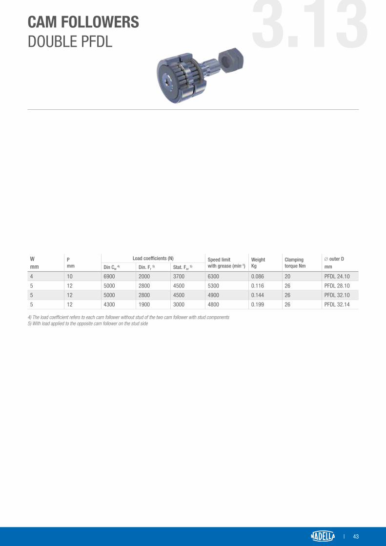
CAM FOLLOWERSDOUBLE PFDLFor assembling on double contact cam movements. Outer diameter of cam follower without stud from 24 to 32 mm
D
R
r
C
a a
dA
P
G
WG1
B2
d1
C1
B1
LPFDL perni folli doppi
∅ outer Dmm
Designation 1) d1 2)
mmLmm
B1
mmB2
mmThreading G mm
G1
mmCmm
amm
C1
mmdA
mmrmm
R 3)
mmPFDL
24 PFDL 24.10 10 45 23 21.5 M10 x 1.25 12.5 21 10 1 17.9 1.6 200
28 PFDL 28.10 12 45 22 22.5 M12 x 1.5 13.5 21 10 0.5 20.5 1.6 200
32 PFDL 32.10 12 45 22 22.5 M12 x 1.5 13.5 21 10 0.5 24.5 1.8 250
32 PFDL 32.14 12 60 30 29.5 M12 x 1.5 19 29 14 0.5 24.5 1.8 250
1) Designation PFDL, cam follower with outer cylindrical ring Designation PFD.. cam follower with stud and outer convex rings2) The diameter of the stud is calculated with h6 tolerance3) Convex radius for the PFD version
3.13
Double PFDL
| 43
CAM FOLLOWERSDOUBLE PFDL
Wmm
Pmm
Load coefficients (N) Speed limitwith grease (min-1)
Weight Kg
Clamping torque Nm
∅ outer DmmDin Cw
4) Din. Fr 5) Stat. For 5)
4 10 6900 2000 3700 6300 0.086 20 PFDL 24.10
5 12 5000 2800 4500 5300 0.116 26 PFDL 28.10
5 12 5000 2800 4500 4900 0.144 26 PFDL 32.10
5 12 4300 1900 3000 4800 0.199 26 PFDL 32.14 4) The load coefficient refers to each cam follower without stud of the two cam follower with stud components 5) With load applied to the opposite cam follower on the stud side
3.13
44 |
| 45
SPECIALAPPLICATIONS
PAGE 46 4.1 SPECIAL APPLICATIONS• Cam followers without stud with special connections to the greasing
system• Cam followers without stud for cams and indexers• Anti-corrosion cam followers without stud• Other products with special shape• Cam followers without stud for high/low temperature• Cam followers without stud for vacuum• Wear-resistant materials• Mirror finishing
PAGE 48 4.2 OTHER PRODUCTS WITH SPECIAL SHAPE
4

46 |
4.1SPECIALAPPLICATIONSAs well as the products in the catalogue, Nadella also designs and manufactures special needle and roller cam followers for specific applications. There can be variations on standard products or completely special products. Here are some examples:
CAM FOLLOWER WITHOUT STUD WITH SPECIAL CONNECTIONS TO THE GREASING SYSTEM
PFDL28.10 with threaded hole to connect to the grease dispensing system. The full complement needle follower generally requires periodical greasing or, for more load and speed strained applications, the oil-filled function. An additional threaded hole in the stud was added to simplify periodical re-greasing connecting the cam roller to a centralised dispensing system.
PK52CNX LB cam followers without stud.The PK series cam followers without stud with tapered bearings are normal-ly considered greased for life. In some environments, for example, where there is a high humidity level, the grease might deteriorate over time and it is, therefore, advisable to take into consideration the possibility of having to top up the grease. The LB option for guide wheels with stud allows you to connect the nipple or plug screw to the threaded hole. For cam followers without stud and with through hole, this allows the grease to be inserted from the pivot (create hole and circular groove on the assembly pivot).
NOTI
CE: T
HIS
DRAW
ING
CONT
AINS
PRO
PRIE
TARY
INFO
RMAT
ION
OF N
ADEL
LA A
ND IS
NOT
TO
BE D
ISCL
OSED
TO
OTHE
RS W
ITHO
UT T
HE E
XPRE
SSED
WRI
TTEN
APP
ROVA
L OF
NAD
ELLA
28Ø
h6
12M
x 1
,5
6M
45
10 10
12Ø
h6
0,51
A-A ( 1,5 : 1 )
NOTI
CE: T
HIS
DRAW
ING
CONT
AINS
PRO
PRIE
TARY
INFO
RMAT
ION
OF N
ADEL
LA A
ND IS
NOT
TO
BE D
ISCL
OSED
TO
OTHE
RS W
ITHO
UT T
HE E
XPRE
SSED
WRI
TTEN
APP
ROVA
L OF
NAD
ELLA
M6B-B ( 1,5 : 1 )
NOTI
CE: T
HIS
DRAW
ING
CONT
AINS
PRO
PRIE
TARY
INFO
RMAT
ION
OF N
ADEL
LA A
ND IS
NOT
TO
BE D
ISCL
OSED
TO
OTHE
RS W
ITHO
UT T
HE E
XPRE
SSED
WRI
TTEN
APP
ROVA
L OF
NAD
ELLA
Nadella
Smussi non quotati
lavorazione generaleMateriale
Trattamenti termici Finitura superficiale
Tolleranze generali secondo EN 22768-1 classe m
Stato
Durezza Prof. TT sul finito
Data
CodiceRif.
Form.
Scala
Verif.
Dis.
Rev.Descrizione
> 6± 0.1
> 30± 0.2
> 120± 0.3
> 400± 0.5
> 1000± 0.8
> 2000± 1.2
> 4000± 2
0.2x45°
31/07/2015
1:1
Peso
CAM FOLLOWERS FOR CAMS AND INDEXERS
In the case of more complex mechanical applications, cam followers with-out stud are manufactured with materials, processing cycles, finishings, di-mensional tolerances and radial play that are optimised to increase rigidity, load capacity and precision as much as possible.
44
35Ø
h5 A
0,005
20Ø
h5
18
0,02 A
0,010
34,2 [1.346 in]
25,4
h6
[1 h
6 in
]Ø
15,88 [0.625 in]
15,8
75 h
5 [0
.625
h5
in]
Ø

| 47
ANTI-CORROSION CAM FOLLOWERS WITHOUT STUD
The cam followers without stud and full complement needle followers can be supplied in anti-corrosion NX version. Nadella offers stainless steel or protected cam followers without stud with surface treatments. The stainless steel used is AISI 400 and achieves a hardness comparable to steel for bear-ings but has a limited resistance to corrosion. The inner needles can be in stainless steel or more commonly in 100Cr6 steel. In this case the corrosion protection of the needles is entrusted to grease (NSF H1 classified grease for alimentary use and resistant to humidity). Nuts and washers are supplied in A2 stainless steel, the greasing nipple in raw brass or stainless steel.
As an alternative to the stainless steel versions hard nickel or hard chrome treatments can be used.
Different solutions can be configured based on the environment in which it is applied
• NX-11: is the most common version that has outer parts in stainless steel, protected with chrome treatment and standard steel rollers and needles for bearings.
• NX-12: stainless steel outer ring, other protected components with nickel treatment and standard steel rollers and needles for bearings.
• NX-17: entirely in stainless steel.
• NX-18: protection using hard chrome and standard steel needles for bearings. This is the best option for small production batches.
CAM FOLLOWERS WITHOUT STUD FOR HIGH/LOW TEMPERATURE
These require suitable grease and stabilisation of the material for expected operating temperature.
CAM FOLLOWERS WITHOUT STUD FOR VACUUM
Entirely in stainless steel and slow evaporating grease.
WEAR-RESISTANT MATERIALS
Cam followers without stud with stainless outer ring for wear-resistant tools.
SURFACE FINISHINGS
Mirror polishing and oxidisation to add the colour black.

48 |
4.2OTHER PRODUCTSWITH SPECIAL SHAPE
12Ø
15
32S
Ø
Ø32
()
Ø7,
8
16Ø
10
28,5
Ø25
,4 [
1 in
]
76,2
Ø
[ 3
in ]
47,125 [ 1 3/8 in ]
16Ø
19Ø Ø
10M6
42,5
1111
6M12Ø
32
18
72
110
28Ø
52Ø

| 49
NOTES

50 |

| 51
ACCESSORIES
PAGE 52 5.1 ACCESSORIES FOR CAM FOLLOWERS WITH STUD• Eccentric collars• Nut and washer• Nipple and greasing plug• Greasing injector
5
52 |
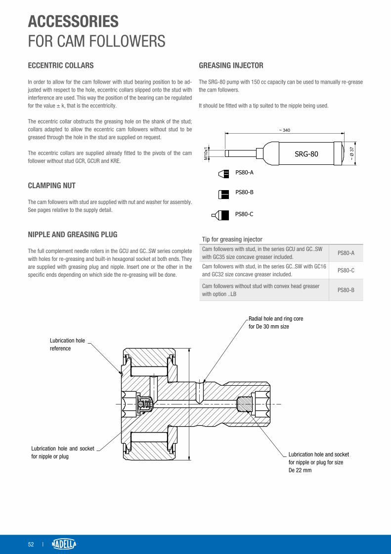
ACCESSORIESFOR CAM FOLLOWERSECCENTRIC COLLARS
In order to allow for the cam follower with stud bearing position to be ad-justed with respect to the hole, eccentric collars slipped onto the stud with interference are used. This way the position of the bearing can be regulated for the value ± k, that is the eccentricity.
The eccentric collar obstructs the greasing hole on the shank of the stud; collars adapted to allow the eccentric cam followers without stud to be greased through the hole in the stud are supplied on request.
The eccentric collars are supplied already fitted to the pivots of the cam follower without stud GCR, GCUR and KRE.
CLAMPING NUT
The cam followers with stud are supplied with nut and washer for assembly. See pages relative to the supply detail.
NIPPLE AND GREASING PLUG
The full complement needle rollers in the GCU and GC..SW series complete with holes for re-greasing and built-in hexagonal socket at both ends. They are supplied with greasing plug and nipple. Insert one or the other in the specific ends depending on which side the re-greasing will be done.
GREASING INJECTOR
The SRG-80 pump with 150 cc capacity can be used to manually re-grease the cam followers.
It should be fitted with a tip suited to the nipple being used.
NOTI
CE: T
HIS
DRAW
ING
CONT
AINS
PRO
PRIE
TARY
INFO
RMAT
ION
OF N
ADEL
LA A
ND IS
NOT
TO
BE D
ISCL
OSED
TO
OTHE
RS W
ITHO
UT T
HE E
XPRE
SSED
WRI
TTEN
APP
ROVA
L OF
NAD
ELLA
PS80-A
PS80-B
SRG-80
~ 340
37~
Ø
10M
x1
PS80-C
Tip for greasing injectorCam followers with stud, in the series GCU and GC..SW with GC35 size concave greaser included.
PS80-A
Cam followers with stud, in the series GC..SW with GC16 and GC32 size concave greaser included.
PS80-C
Cam followers without stud with convex head greaser with option ..LB
PS80-B
NOTI
CE: T
HIS
DRAW
ING
CONT
AINS
PRO
PRIE
TARY
INFO
RMAT
ION
OF N
ADEL
LA A
ND IS
NOT
TO
BE D
ISCL
OSED
TO
OTHE
RS W
ITHO
UT T
HE E
XPRE
SSED
WRI
TTEN
APP
ROVA
L OF
NAD
ELLA
Foro di lubrificazione e sedeper nipplo o tappo dalla taglia De 22 mm
Foro radiale e cava anularedalla taglia De 30 mm
Riferimento foro di lubrificazione
Foro di lubrificazione e sedeper nipplo o tappo
Lubrication holereference
Lubrication hole and socket for nipple or plug
Radial hole and ring corefor De 30 mm size
Lubrication hole and socketfor nipple or plug for sizeDe 22 mm

| 53
NOTES 5.1

54 |
| 55
TECHNICAL SPECIFICATIONS 6PAGE 56 6.1 TECHNICAL SPECIFICATIONS
• Reference standards• Load capacity• Precision• Radial play• Selection of seal type• Greasing operating temperature• Optimised profile• Alignment tolerance permitted between roller and track• Assembly instructions
56 |
TECHNICALSPECIFICATIONSREFERENCE STANDARDS
The cam followers in the series GC, KR, FG, GCU and FGU comply with standards: ISO 6278 – Contrast rollers – Bulk dimensionsISO 7063 – Contrast rollers – Tolerances
LOAD CAPACITY
The cam follower is generally used as a wheel that runs on a guide or cam. The load is applied to the cam follower without stud at the contact point with the race track and, unlike a bearing, the outer ring is not kept in the case and is free to deform. The elastic deformation of the outer ring affects the load distribution between the rolling bearing elements reducing the capacity calculated in compliance with ISO standards for bearings.
The dimensional tables show the load values
• The Cw load coefficient to be used to calculate the duration t. Keep in mind the bearing's load capacity C in compliance with ISO281 based on the rigidity of the outer ring.
Cw : dynamic load coefficient of the cam follower without stud for 106 revsfw : overload factorPr : radial load applied in NL10 : duration calculated in millions of revsLh : duration in hoursLkm : duration in kmn : average speed in revs/minute
The maximum load applicable to the cam followers without stud takes into consideration the acceptable load from the bearing (Co in accordance with ISO 76 reduced on the basis of the rigidity of the outer ring), the resistance of the outer ring and, for cam followers with stud, the resistance of the stud's resistance. The tables show the applicable limit load.
• Dynamic load limit Fr: this is the load which should not be exceeded when the cam followers without stud are subject to repeated strain.
• Static load limit For: this is the static resistance limit that the cam fol-lower without stud can bear under exceptional conditions and should never be exceeded.
The safety coefficient fs can be calculated as
fs = Fr / Pr
Fr: Product dynamic limit load
In any event, the applied load Pr needs to be lower than the product's static load For.
The load limit Fr and For for the cam followers with stud in the product tables refers to the concentric version. Assessment will need to be made as to whether the eccentric load can rotate the pivot in its seating, if the GCR or GCUR or KRE eccentric version is used.
Furthermore, the rolling track resistance needs to be taken into considera-tion. The assessment method adopted is based on the calculation of the Hertz pressure compared to the pressure accepted by the cam material.
The product catalogue data refers to the standard steel version. The stain-less steel products or those stabilised by high temperature have a reduced load capacity.
Contact Nadella Technical Assistance for more details.
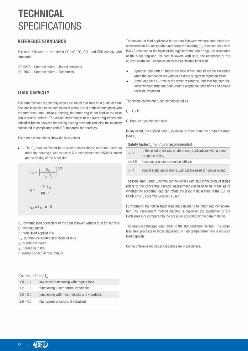
Cw 10/3
L10 = ( ) fw · Pr
106 · L10Lh = 60 · n
Lkm = L10 · π · D
Overload factor fw
1.0 - 1.2 low speed functioning with regular load
1.2 - 1.5 functioning under normal conditions
1.5 - 2.0 functioning with minor shocks and vibrations
2.0 - 4.0 high speed, shocks and vibrations
Safety factor fs minimum recommended
>=3in the event of shocks or vibrations, applications with a need for gentle rolling
>=1.5 functioning under normal conditions
>=1 almost static applications, without the need for gentle rolling

| 57
PRECISION
Cam followers with stud in the series GC, GCU, FG, FGU, KR refer to the dimensions in standard ISO 6278.The reference standard for the same products is ISO 7063.The cam follower manufacturing tolerance given in the tables below are generally more restrictive compared to the reference standard, but in any event, still compliant with the standard.In particular, the outer diameter of the cam followers without stud is pro-duced in h6 or h7 tolerance even for the versions with profiled or convex outer ring
RADIAL PLAY
The radial play of the standard cam followers without stud normally falls into category C2 established for needle roller bearings in compliance with standard ISO 5753-1.
TECHNICALSPECIFICATIONS
Cam follower without stud outer diameter tolerance D GC / PF / FG / FL / PFDL / GCU / FGUUp to diameter 32 inclusive h6
Beyond diameter 32 h7
Max error on rotationGC / PF / FG / FL / PFDL / GCU / FGU
Diameter d Kea um
10 18 15
18 30 15
30 50 20
50 80 25
80 120 35
120 150 40
150 180 45
180 240 50
Diameter tolerance on cam follower stud d1
GC / PF / PFDL / GCUAll dimensions h6
Cam follower hole tolerance d (Micron)GC / PF / PFDL / GCU
Diameter d Tolerance um
from up to upper lower
3 10 0 -8
10 18 0 -8
18 30 0 -10
30 50 0 -12
50 80 0 -15
80 120 0 -20
120 180 0 -25
6.1

58 |
TECHNICALSPECIFICATIONSSELECTION OF SEAL TYPE
The key function of the seals is to protect the bearing from its surrounding environment and treat the grease inside.
• The cam followers with no seal are shown in the applications with oil greasing coming from outside the cam follower without stud (typically high load and speed cams) where it is essential to allow for the entry of the oil in the bearing for greasing and cooling.
• The cam followers with stud in series GC and FG with a diameter of 16 inclusive can fit seals:
- EEM type, of metal guards, are mechanically resistant and suited to any temperature.
- EE type seal is manufactured with a Teflon ring in contact with the moving parts. The seal's maximum operating temperature is 220°C.
• Cam followers with stud in the GCU series can be fitted with MM type seals that act as labyrinth metal guards and are suited to any temperature.
• Cam followers without stud in the FGU series can be fitted with MM type seals that act as metal guards and are suited to any temperature.
• The cam followers without stud in the KK..EE series are fitted with plastic seals (not Teflon) integrated with the outer ring's axial contain-ment abutment.
• The cam followers without stud in the PK and FK series fitted with RS type seals in NBR, can be used up to a temperature of 80°C. For temperatures in excess of this, the cam followers without stud up to and including size 90 can be fitted with Viton seals (suffix V). The ac-ceptable temperature of the seal is 200°C.
OPERATIONAL GREASING AND SEAL
The type of cam followers shown in this catalogue, with the exception of the RNA type cam followers without stud are supplied with a grease that permits an operating temperature from -20°C to 120°C. The stainless steel cam followers without stud use a category NSF H1 grease for alimentary purposex.
The RNA 11000 type cam followers without stud are supplied with a pro-tection compatible to a lithium soap based grease. As with bearings, the protection is unsuited for greasing the cam followers without stud. The maximum operating temperature depends on the grease used.
For cam followers and full complement needle followers GC, GCU and de-rivatives, with metal or plastic seals (EE - Teflon), the operating temperature limit depends on the grease and in the case of standard cam followers without stud, is between -20°C and 120°C.
For full complement needle rollers with cage, the operating temperature is between -20°C and 80°C.
The cam followers without stud with tapered bearings type PK and FK are supplied already greased and in the standard version can operate between -20°C and 80°C (standard seals in NBR) or 120°C (seals in Viton). a suitable grease needs to be used for a higher temperature.
Greased bearings can be provided with suitable grease at high or low tem-peratures, or with no grease.
For high temperatures starting at 150°C, the products need to undergo sta-bilising heat treatment which involves a reduction of hardness and load capacity.

| 59
6.1OPTIMISED PROFILE
Cam rollers are generally used in contact with the cams or sliding guidex. The contact between the surface of the guide or cam and cam follower without stud is selected on the basis of the application considering the strain caused on the material and the consequences of any misalignments. Cam followers without stud with constant radius convex outer ring. The theoretical point of contact under the effect of elastic deformations caused by the load converts into a surface, the contact pressure is calculated with the classic Hertz formulae and has a parabolic tendency with maximum strain in the centre of the contact area. The maximum value is taken as reference for the resistance assessment requested of the rolling track. As the diameter of the cam follower without stud and the convex radius ex-pands, the contact pressure drops. Any misalignment of the cam follow-er without stud moves the contact zone without modifying dimension or strain. This is a solution suited to the application with an average load and relatively inexact geometries, typically applications for a linear movement. Cam followers without stud with cylindrical outer ring. The theoretical con-tact line under the effect of the contact load opens onto a vast surface reducing the average and maximum pressure. As an initial estimate according to the Hertz formulae with equal load, the strain and deformation are considerably lower compared to the contact with the convex cam roller without stud but two important considerations need to be made: 1) at the ends of the contact line, due to the edge, there is a peak in the strain which, in practical terms, reduces the difference compared to the previous case 2) the effect of a mis-alignment, even a minor one, moves the contact to an extreme prejudicing the contact itself and even the load which weighs on the bearing below. This is a solution suited to applications with a high load and which require the machine to make careful mechanical processings to avoid misalignments. Cam followers without stud with optimised profile outer ring. The profile of the cam follower without stud is created with a wide radius in the central part of the sleeve that decreases by moving away from the central line of the cam follower without stud. When the cam follower without stud is properly aligned, the wide radius allows for a vast contact area and ex-cellent distribution of the load; in the event of misalignment between the track and cam follower without stud, the contact moves in a similar fashion to the convex cam followers without reaching the edge of the strip, thus protecting the track and inner bearing against abnormal strain. This is a solution suited both to applications that require a high level of load ac-curacy and rigidity as well as to applications with misalignments. The cam followers without stud with optimised profile are identified by the SW suffix.
ALIGNMENT TOLERANCE PERMITTED BETWEEN ROLLER AND TRACK
Cam followers without stud with convex outer ring or optimised profile allow for an inclination compared to the surface of the track, up to a maximum as shown in the table.
Cam follower without stud type Inclination Δ
RNA 11 000 B6 1.5 per 1000
Cam followers FG, GC, GCU with convex outer ring or optimised profile
7 per 1000
NOTI
CE: T
HIS
DRAW
ING
CONT
AINS
PRO
PRIE
TARY
INFO
RMAT
ION
OF N
ADEL
LA A
ND IS
NOT
TO
BE D
ISCL
OSED
TO
OTHE
RS W
ITHO
UT T
HE E
XPRE
SSED
WRI
TTEN
APP
ROVA
L OF
NAD
ELLA
NOTI
CE: T
HIS
DRAW
ING
CONT
AINS
PRO
PRIE
TARY
INFO
RMAT
ION
OF N
ADEL
LA A
ND IS
NOT
TO
BE D
ISCL
OSED
TO
OTHE
RS W
ITHO
UT T
HE E
XPRE
SSED
WRI
TTEN
APP
ROVA
L OF
NAD
ELLA
NOTI
CE: T
HIS
DRAW
ING
CONT
AINS
PRO
PRIE
TARY
INFO
RMAT
ION
OF N
ADEL
LA A
ND IS
NOT
TO
BE D
ISCL
OSED
TO
OTHE
RS W
ITHO
UT T
HE E
XPRE
SSED
WRI
TTEN
APP
ROVA
L OF
NAD
ELLA
Rollers with convex outer ring with constant radius
Rollers with cylindrical outer ring
Rollers with convex outer ring with constant radius.
NOTI
CE: T
HIS
DRAW
ING
CONT
AINS
PRO
PRIE
TARY
INFO
RMAT
ION
OF N
ADEL
LA A
ND IS
NOT
TO
BE D
ISCL
OSED
TO
OTHE
RS W
ITHO
UT T
HE E
XPRE
SSED
WRI
TTEN
APP
ROVA
L OF
NAD
ELLA
Nadella
Smussi non quotati
lavorazione generaleMateriale
Trattamenti termici Finitura superficiale
Tolleranze generali secondo EN 22768-1 classe m
Stato
Durezza Prof. TT sul finito
Data
CodiceRif.
Form.
Scala
Verif.
Dis.
Rev.Descrizione
> 6± 0.1
> 30± 0.2
> 120± 0.3
> 400± 0.5
> 1000± 0.8
> 2000± 1.2
> 4000± 2
0.2x45°
30/07/2015
1:1
Peso

60 |
TECHNICALSPECIFICATIONSASSEMBLY INSTRUCTIONS
Direction of the greasing radial hole In the case of use with heavy loads, shocks or vibrations, it is best to avoid the greasing hole ending up in the area in which the load weighs down on the needles, which is the side in contact with the cam or rolling track. The position of the hole in question in the cam followers with stud that is not visible from the outside, is indicated by a reference on the head of the cam follower with stud.
Side rest for the cam followersIn the event of relevant axial loads or functioning in the presence of vibra-tions, we recommend the outer diameter of the rest be at least equal to the dA quota in the dimensions tablex.
Assembly hole diameterThe recommended tolerance for the slot hole in the cam follower with stud is d1 H7.
Assembly pivot diameterThe recommended tolerance for the pivot to be inserted in the cam follow-ers hole in the FG and FGU series is h5.
Nut clampingThe clamping torque given in the table allows the pivot to be clamped se-curely in the housing. An upper clamping torque can damage the product.The clamping torques are taken for non-greased threads; for greased threads, multiply the value of the torque in the table by 0.8.For products in the GC and GCU series supplied with two nuts, clamp the first nut with the recommended torque and then the second one.
Cam followers without stud with eccentric collarThe load applied to the cam follower without stud with eccentric collar gen-erates a clamp that tends to rotate the stud in its housing. In order to avoid this effect generating a movement that could slacken the nut, adjust the ec-centricity so that the cam follower is alongside the rolling track by rotating the stud in the same direction as the nut clamping.
NOTI
CE: T
HIS
DRAW
ING
CONT
AINS
PRO
PRIE
TARY
INFO
RMAT
ION
OF N
ADEL
LA A
ND IS
NOT
TO
BE D
ISCL
OSED
TO
OTHE
RS W
ITHO
UT T
HE E
XPRE
SSED
WRI
TTEN
APP
ROVA
L OF
NAD
ELLA
NOTI
CE: T
HIS
DRAW
ING
CONT
AINS
PRO
PRIE
TARY
INFO
RMAT
ION
OF N
ADEL
LA A
ND IS
NOT
TO
BE D
ISCL
OSED
TO
OTHE
RS W
ITHO
UT T
HE E
XPRE
SSED
WRI
TTEN
APP
ROVA
L OF
NAD
ELLA
NOTI
CE: T
HIS
DRAW
ING
CONT
AINS
PRO
PRIE
TARY
INFO
RMAT
ION
OF N
ADEL
LA A
ND IS
NOT
TO
BE D
ISCL
OSED
TO
OTHE
RS W
ITHO
UT T
HE E
XPRE
SSED
WRI
TTEN
APP
ROVA
L OF
NAD
ELLA
Lubrication hole in the wrong position
Lubrication hole in the right position

| 61
NOTES 6.1

62 |
NOTES

| 63
Vers
ion
08/2
019
Nade
lla S
pA |
nade
lla.c
omEr
rors
and
om
issio
ns e
xcep
ted.
PF19
1ENNADELLA S.p.A.
ItalyVia Melette, 1620128 Milan
Tel. : +39 02 270 93Fax : +39 02 257 64 [email protected]
www.nadella.it
NADELLA GmbH GermanyRudolf-Diesel-Str. 2871154 Nufringen
Tel. : +49 7032 9540-0Fax : +49 7032 [email protected]
www.nadella.de
CHIAVETTE UNIFICATE S.p.A. ItalyVia G.Brodolini 6-8-10 40069 Zola Predosa, Bologna
Tel.: +39 051 75 87 67Fax: +39 051 75 47 [email protected]
www.chiavette.com
NADELLA Linear Shanghai Co. Ltd. ChinaRoom D314, N0.245 Xinjunhuan Road 201114 Minhang Shanghai
Tel. : +86 21 5068 [email protected]
www.nadella.cn.com
NADELLA Inc. United States14115 – 63 Way NorthClearwater – Florida 33760-3621
Toll free: +1 844-537-0330Fax : +1 [email protected]
www.nadella.com
DURBAL Metallwarenfabrik GmbHGermanyVerrenberger Weg 2 74613 Öhringen
Tel.: +49 7941 9460-0Fax: +49 7941 [email protected]
www.durbal.de
Members of Nadella Group