cam followers stud type - nrb industrial … followers – stud type 1 cam followers are designed to...
TRANSCRIPT

CAM FOLLOWERSSTUD TYPE
REGD. OFFICE : DHANNUR, 2ND FLOOR, 15, SIR P. M. RAOD, FORT, MUMBAI - 400 001. INDIATEL: (022) 2270 4206 FAX: (022) 2270 4207
PLANT:PLOT NO. B -18, FIVE STAR M.I.D.C AREA, SHENDRA, AURANGABAD - 431201
TEL: 0240 - 2622180www: nrbindustrialbearings.com
CAM FOLLOWERS – STUD TYPE
1
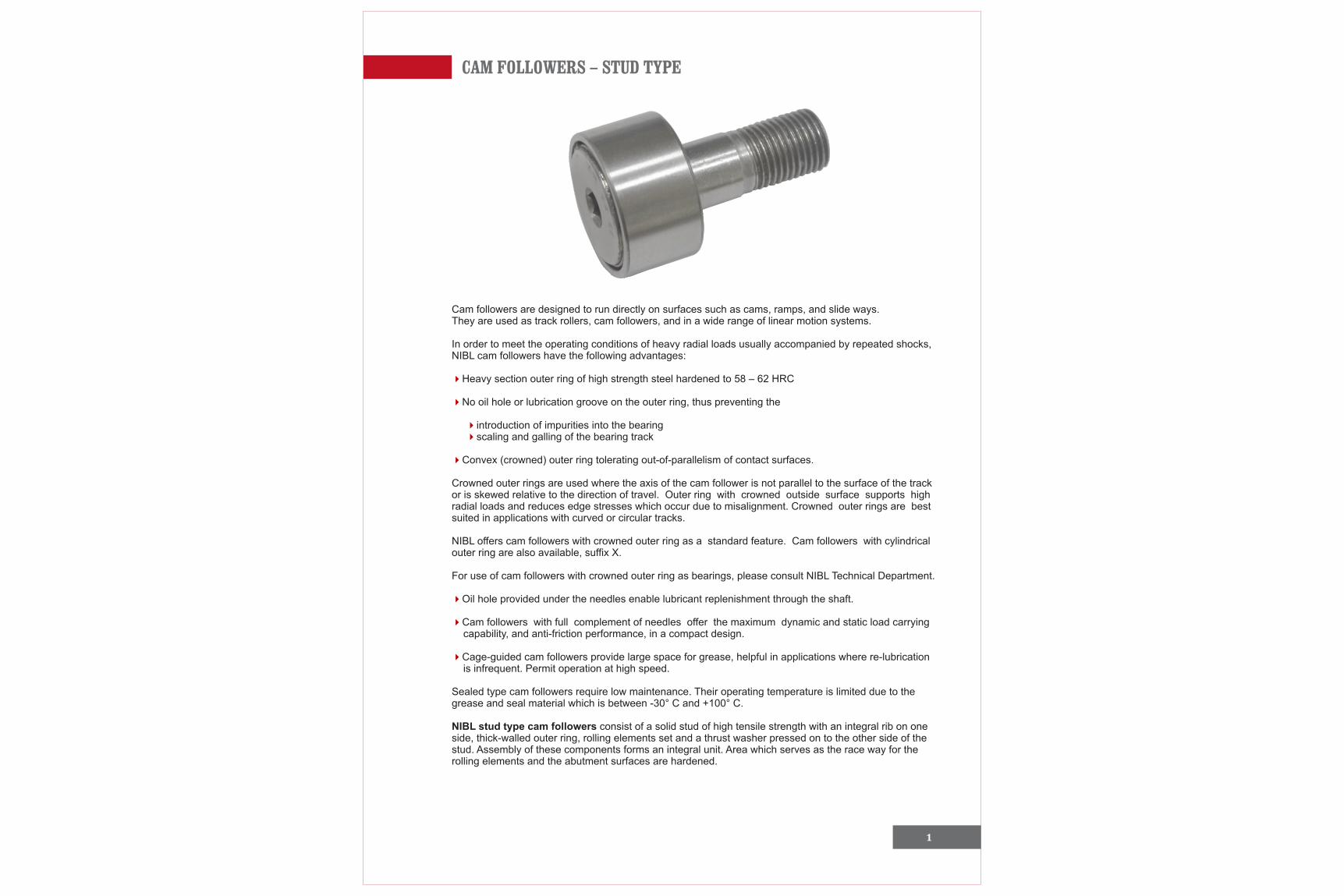
Cam followers are designed to run directly on surfaces such as cams, ramps, and slide ways.They are used as track rollers, cam followers, and in a wide range of linear motion systems.
In order to meet the operating conditions of heavy radial loads usually accompanied by repeated shocks,NIBL cam followers have the following advantages:
Heavy section outer ring of high strength steel hardened to 58 – 62 HRC
No oil hole or lubrication groove on the outer ring, thus preventing the
introduction of impurities into the bearing scaling and galling of the bearing track
Convex (crowned) outer ring tolerating out-of-parallelism of contact surfaces.
Crowned outer rings are used where the axis of the cam follower is not parallel to the surface of the trackor is skewed relative to the direction of travel. Outer ring with crowned outside surface supports highradial loads and reduces edge stresses which occur due to misalignment. Crowned outer rings are bestsuited in applications with curved or circular tracks.
NIBL offers cam followers with crowned outer ring as a standard feature. Cam followers with cylindricalouter ring are also available, suffix X.
For use of cam followers with crowned outer ring as bearings, please consult NIBL Technical Department.
Oil hole provided under the needles enable lubricant replenishment through the shaft.
Cam followers with full complement of needles offer the maximum dynamic and static load carrying capability, and anti-friction performance, in a compact design.
Cage-guided cam followers provide large space for grease, helpful in applications where re-lubrication is infrequent. Permit operation at high speed.
Sealed type cam followers require low maintenance. Their operating temperature is limited due to the grease and seal material which is between -30° C and +100° C.
NIBL stud type cam followers consist of a solid stud of high tensile strength with an integral rib on oneside, thick-walled outer ring, rolling elements set and a thrust washer pressed on to the other side of thestud. Assembly of these components forms an integral unit. Area which serves as the race way for therolling elements and the abutment surfaces are hardened.
4
4
44
4
4
4
4
2
CAM FOLLOWERS – STUD TYPE
Axial guidance to the outer ring is by means of integral rib on the stud and a thrust washer which is pressfitted on to the stud.
For re-lubrication lubrication holes are provided at the ribbed face of the stud as well as at the threadedend. In case of symbols 16 and 19 lubrication hole is at the ribbed face only. Additional lubrication holesare provided in the stud for cam followers with an outside diameter of 30 mm and above.
Threads on the end of the stud, hexagonal socket in the ribbed face and threads side of the stud areprovided for ease of mounting. In case of symbols 16 and 19 threads on the end of the stud and a screwdriver slot is provided in the ribbed face.
, different design variations of stud type cam followers are available:
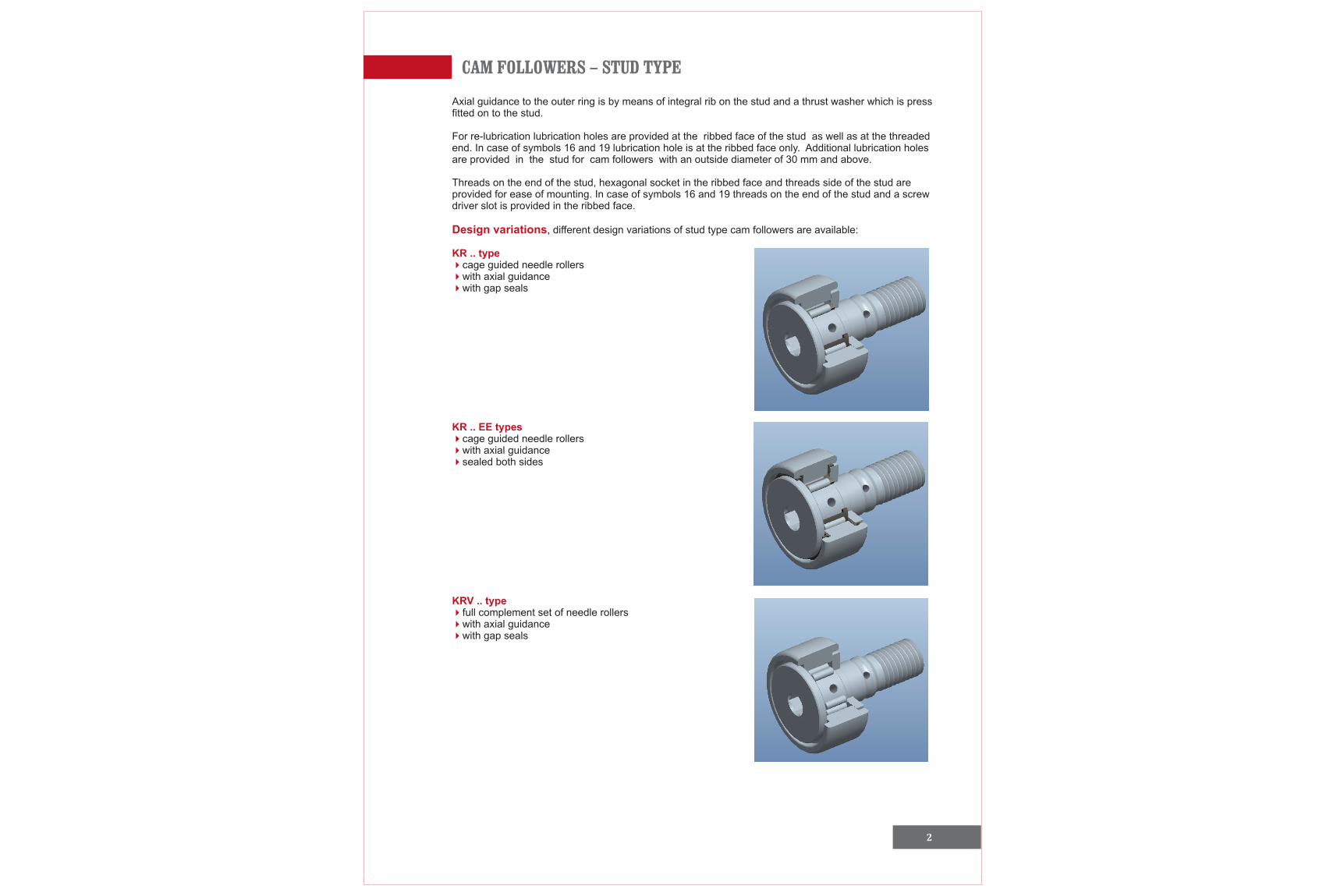
cage guided needle rollerswith axial guidancewith gap seals
cage guided needle rollerswith axial guidancesealed both sides
full complement set of needle rollerswith axial guidancewith gap seals
Design variations
KR .. type444
KR .. EE types
44
KRV .. type444
4
CAM FOLLOWERS – STUD TYPE
3
KRV .. EE type444
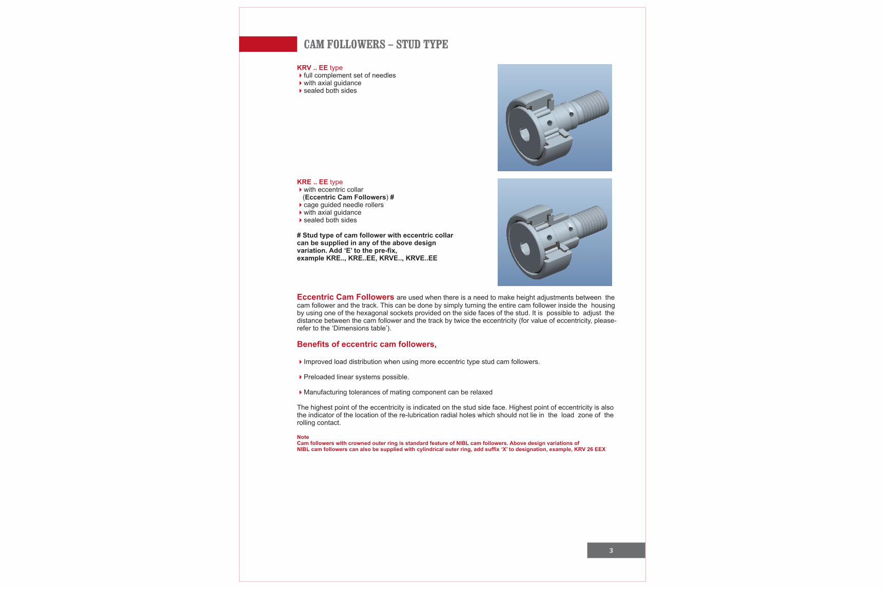
KRE .. EE type4
444
Eccentric Cam Followers
Benefits of eccentric cam followers,
4
4
4
NoteCam followers with crowned outer ring is standard feature of NIBL cam followers. Above design variations of NIBL cam followers can also be supplied with cylindrical outer ring, add suffix ‘X’ to designation, example, KRV 26 EEX
full complement set of needleswith axial guidancesealed both sides
with eccentric collar (Eccentric Cam Followers) #
cage guided needle rollerswith axial guidance sealed both sides
# Stud type of cam follower with eccentric collarcan be supplied in any of the above designvariation. Add ‘E’ to the pre-fix,example KRE.., KRE..EE, KRVE.., KRVE..EE
are used when there is a need to make height adjustments between thecam follower and the track. This can be done by simply turning the entire cam follower inside the housingby using one of the hexagonal sockets provided on the side faces of the stud. It is possible to adjust thedistance between the cam follower and the track by twice the eccentricity (for value of eccentricity, please-refer to the ‘Dimensions table’).
Improved load distribution when using more eccentric type stud cam followers.
Preloaded linear systems possible.
Manufacturing tolerances of mating component can be relaxed
The highest point of the eccentricity is indicated on the stud side face. Highest point of eccentricity is alsothe indicator of the location of the re-lubrication radial holes which should not lie in the load zone of therolling contact.
CAM FOLLOWERS – STUD TYPE
4 5
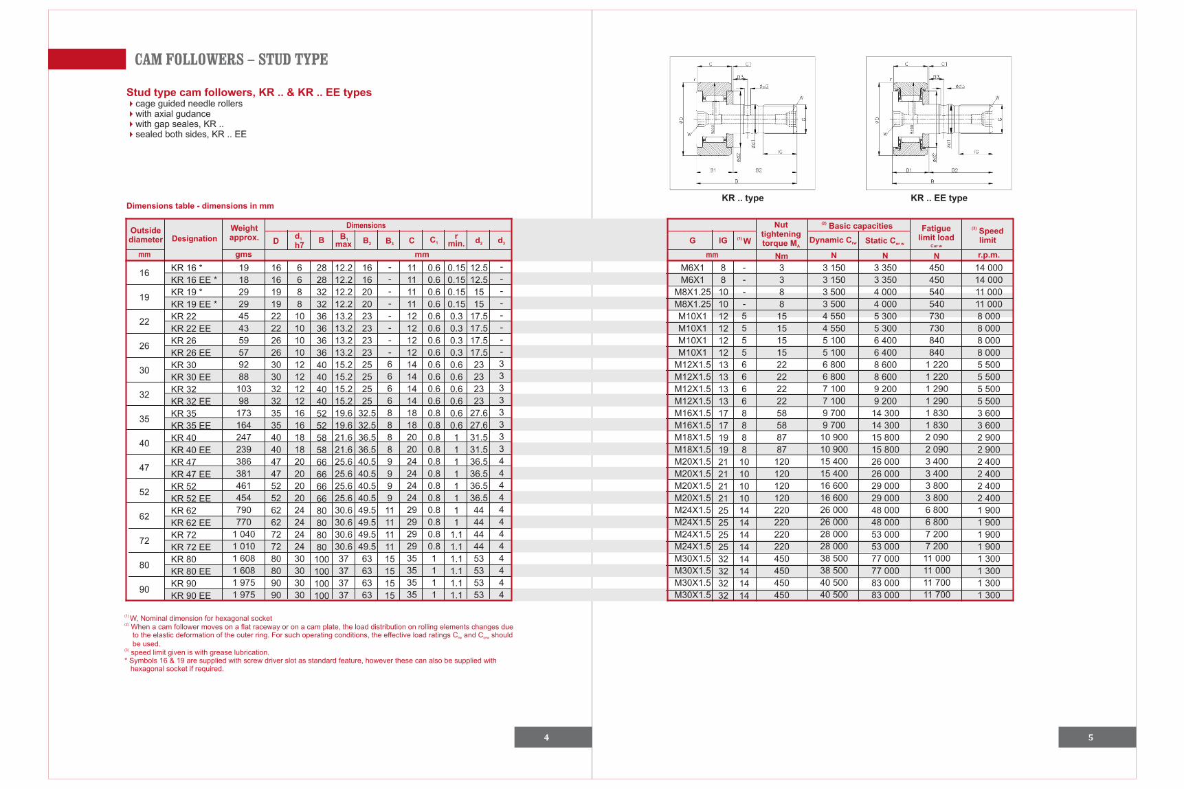
Stud type cam followers, KR .. & KR .. EE types4444
cage guided needle rollerswith axial gudancewith gap seales, KR ..sealed both sides, KR .. EE
KR .. type KR .. EE typeDimensions table - dimensions in mm
mm
Designation
DimensionsOutsidediameter
Weight approx.
gms
Dd1
h7B
B 1
max
B2 B 3 C C1
rmin. d2 d3 G
mm mm N N N
lG (1) W
Nut tighteningtorque MA
(2) Basic capacities Fatiguelimit load
Cur w
(3) Speedlimit
Nm
Dynamic Crw Static Cor w
r.p.m.
16
19
22
26
30
32
35
40
47
52
62
72
80
90
KR 16 *
KR 16 EE *
KR 19 *
KR 19 EE *
KR 22
KR 22 EE
KR 26
KR 26 EE
KR 30
KR 30 EE
KR 32
KR 32 EE
KR 35
KR 35 EE
KR 40
KR 40 EE
KR 47
KR 47 EE
KR 52
KR 52 EE
KR 62
KR 62 EE
KR 72
KR 72 EE
KR 80
KR 80 EE
KR 90
KR 90 EE
19
18
29
29
45
43
59
57
92
88
103
98
173
164
247
239
386
381
461
454
790
770
1 040
1 010
1 608
1 608
1 975
1 975
16
16
19
19
22
22
26
26
30
30
32
32
35
35
40
40
47
47
52
52
62
62
72
72
80
80
90
90
6
6
8
8
10
10
10
10
12
12
12
12
16
16
18
18
20
20
20
20
24
24
24
24
30
30
30
30
28
28
32
32
36
36
36
36
40
40
40
40
52
52
58
58
66
66
66
66
80
80
80
80
100
100
100
100
12.2
12.2
12.2
12.2
13.2
13.2
13.2
13.2
15.2
15.2
15.2
15.2
19.6
19.6
21.6
21.6
25.6
25.6
25.6
25.6
30.6
30.6
30.6
30.6
37
37
37
37
16
16
20
20
23
23
23
23
25
25
25
25
32.5
32.5
36.5
36.5
40.5
40.5
40.5
40.5
49.5
49.5
49.5
49.5
63
63
63
63
-
-
-
-
-
-
-
-
6
6
6
6
8
8
8
8
9
9
9
9
11
11
11
11
15
15
15
15
11
11
11
11
12
12
12
12
14
14
14
14
18
18
20
20
24
24
24
24
29
29
29
29
35
35
35
35
0.6
0.6
0.6
0.6
0.6
0.6
0.6
0.6
0.6
0.6
0.6
0.6
0.8
0.8
0.8
0.8
0.8
0.8
0.8
0.8
0.8
0.8
0.8
0.8
1
1
1
1
0.15
0.15
0.15
0.15
0.3
0.3
0.3
0.3
0.6
0.6
0.6
0.6
0.6
0.6
1
1
1
1
1
1
1
1
1.1
1.1
1.1
1.1
1.1
1.1
12.5
12.5
15
15
17.5
17.5
17.5
17.5
23
23
23
23
27.6
27.6
31.5
31.5
36.5
36.5
36.5
36.5
44
44
44
44
53
53
53
53
-
-
-
-
-
-
-
-
3
3
3
3
3
3
3
3
4
4
4
4
4
4
4
4
4
4
4
4
M6X1
M6X1
M8X1.25
M8X1.25
M10X1
M10X1
M10X1
M10X1
M12X1.5
M12X1.5
M12X1.5
M12X1.5
M16X1.5
M16X1.5
M18X1.5
M18X1.5
M20X1.5
M20X1.5
M20X1.5
M20X1.5
M24X1.5
M24X1.5
M24X1.5
M24X1.5
M30X1.5
M30X1.5
M30X1.5
M30X1.5
8
8
10
10
12
12
12
12
13
13
13
13
17
17
19
19
21
21
21
21
25
25
25
25
32
32
32
32
-
-
-
-
5
5
5
5
6
6
6
6
8
8
8
8
10
10
10
10
14
14
14
14
14
14
14
14
3
3
8
8
15
15
15
15
22
22
22
22
58
58
87
87
120
120
120
120
220
220
220
220
450
450
450
450
3 150
3 150
3 500
3 500
4 550
4 550
5 100
5 100
6 800
6 800
7 100
7 100
9 700
9 700
10 900
10 900
15 400
15 400
16 600
16 600
26 000
26 000
28 000
28 000
38 500
38 500
40 500
40 500
3 350
3 350
4 000
4 000
5 300
5 300
6 400
6 400
8 600
8 600
9 200
9 200
14 300
14 300
15 800
15 800
26 000
26 000
29 000
29 000
48 000
48 000
53 000
53 000
77 000
77 000
83 000
83 000
450
450
540
540
730
730
840
840
1 220
1 220
1 290
1 290
1 830
1 830
2 090
2 090
3 400
3 400
3 800
3 800
6 800
6 800
7 200
7 200
11 000
11 000
11 700
11 700
14 000
14 000
11 000
11 000
8 000
8 000
8 000
8 000
5 500
5 500
5 500
5 500
3 600
3 600
2 900
2 900
2 400
2 400
2 400
2 400
1 900
1 900
1 900
1 900
1 300
1 300
1 300
1 300
(1) W, Nominal dimension for hexagonal socket(2) When a cam follower moves on a flat raceway or on a cam plate, the load distribution on rolling elements changes due to the elastic deformation of the outer ring. For such operating conditions, the effective load ratings C and C shouldrw orw
be used.(3) speed limit given is with grease lubrication.* Symbols 16 & 19 are supplied with screw driver slot as standard feature, however these can also be supplied with hexagonal socket if required.
CAM FOLLOWERS – STUD TYPE
6 7
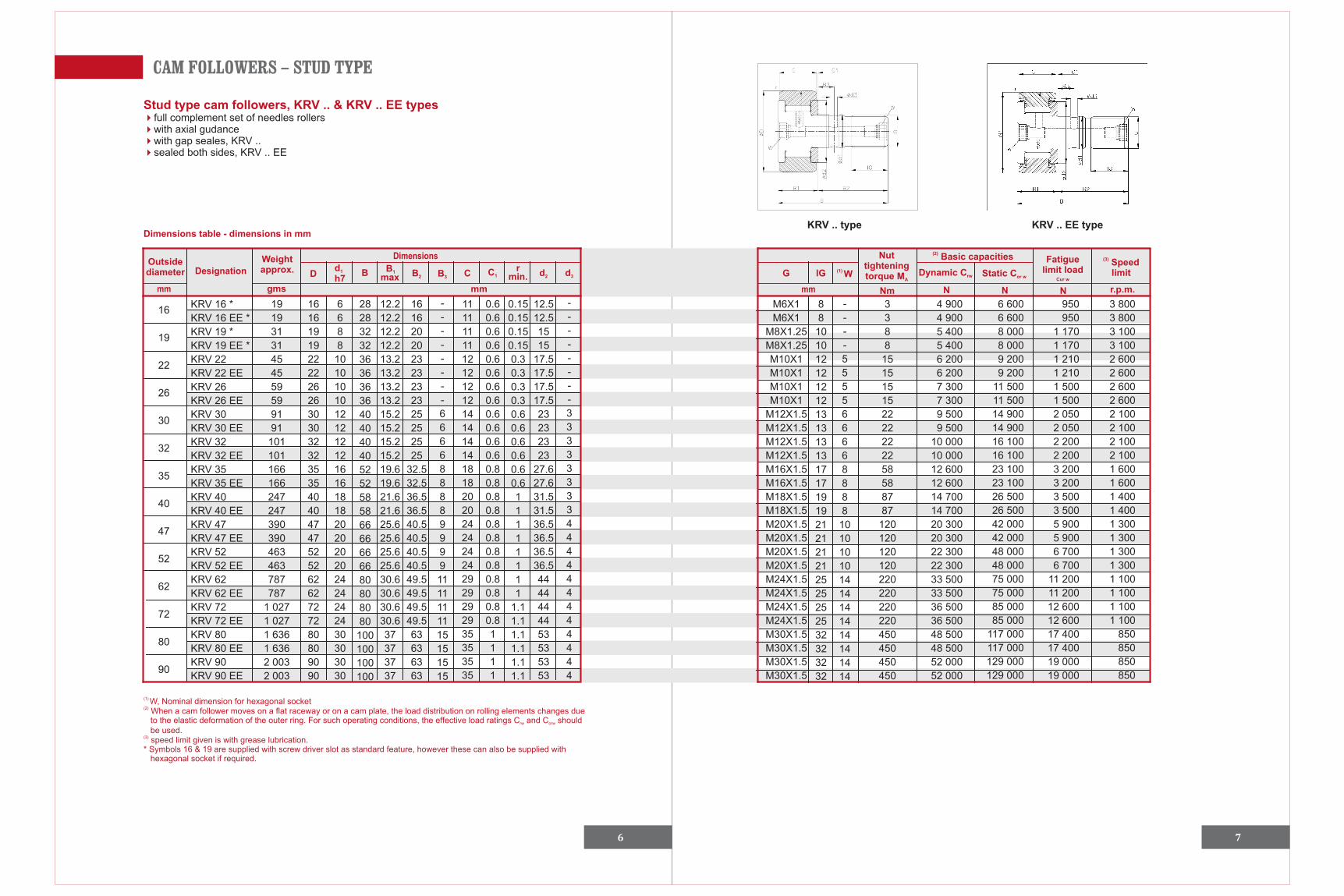
Stud type cam followers, KRV .. & KRV .. EE types4444
full complement set of needles rollerswith axial gudancewith gap seales, KRV ..sealed both sides, KRV .. EE
KRV .. type KRV .. EE typeDimensions table - dimensions in mm
mm
Designation
DimensionsOutsidediameter
Weight approx.
gms
Dd1
h7B
B 1
max
B2 B 3 C C1
rmin. d2 d3 G
mm mm N N N
lG (1) W
Nut tighteningtorque MA
(2) Basic capacities Fatiguelimit load
Cur w
(3) Speedlimit
Nm
Dynamic Crw Static Cor w
r.p.m.
16
19
22
26
30
32
35
40
47
52
62
72
80
90
16
16
19
19
22
22
26
26
30
30
32
32
35
35
40
40
47
47
52
52
62
62
72
72
80
80
90
90
6
6
8
8
10
10
10
10
12
12
12
12
16
16
18
18
20
20
20
20
24
24
24
24
30
30
30
30
28
28
32
32
36
36
36
36
40
40
40
40
52
52
58
58
66
66
66
66
80
80
80
80
100
100
100
100
12.2
12.2
12.2
12.2
13.2
13.2
13.2
13.2
15.2
15.2
15.2
15.2
19.6
19.6
21.6
21.6
25.6
25.6
25.6
25.6
30.6
30.6
30.6
30.6
37
37
37
37
16
16
20
20
23
23
23
23
25
25
25
25
32.5
32.5
36.5
36.5
40.5
40.5
40.5
40.5
49.5
49.5
49.5
49.5
63
63
63
63
-
-
-
-
-
-
-
-
6
6
6
6
8
8
8
8
9
9
9
9
11
11
11
11
15
15
15
15
11
11
11
11
12
12
12
12
14
14
14
14
18
18
20
20
24
24
24
24
29
29
29
29
35
35
35
35
0.6
0.6
0.6
0.6
0.6
0.6
0.6
0.6
0.6
0.6
0.6
0.6
0.8
0.8
0.8
0.8
0.8
0.8
0.8
0.8
0.8
0.8
0.8
0.8
1
1
1
1
0.15
0.15
0.15
0.15
0.3
0.3
0.3
0.3
0.6
0.6
0.6
0.6
0.6
0.6
1
1
1
1
1
1
1
1
1.1
1.1
1.1
1.1
1.1
1.1
12.5
12.5
15
15
17.5
17.5
17.5
17.5
23
23
23
23
27.6
27.6
31.5
31.5
36.5
36.5
36.5
36.5
44
44
44
44
53
53
53
53
-
-
-
-
-
-
-
-
3
3
3
3
3
3
3
3
4
4
4
4
4
4
4
4
4
4
4
4
M6X1
M6X1
M8X1.25
M8X1.25
M10X1
M10X1
M10X1
M10X1
M12X1.5
M12X1.5
M12X1.5
M12X1.5
M16X1.5
M16X1.5
M18X1.5
M18X1.5
M20X1.5
M20X1.5
M20X1.5
M20X1.5
M24X1.5
M24X1.5
M24X1.5
M24X1.5
M30X1.5
M30X1.5
M30X1.5
M30X1.5
8
8
10
10
12
12
12
12
13
13
13
13
17
17
19
19
21
21
21
21
25
25
25
25
32
32
32
32
-
-
-
-
5
5
5
5
6
6
6
6
8
8
8
8
10
10
10
10
14
14
14
14
14
14
14
14
3
3
8
8
15
15
15
15
22
22
22
22
58
58
87
87
120
120
120
120
220
220
220
220
450
450
450
450
(1) W, Nominal dimension for hexagonal socket(2) When a cam follower moves on a flat raceway or on a cam plate, the load distribution on rolling elements changes due to the elastic deformation of the outer ring. For such operating conditions, the effective load ratings C and C shouldrw orw
be used.(3) speed limit given is with grease lubrication.* Symbols 16 & 19 are supplied with screw driver slot as standard feature, however these can also be supplied with hexagonal socket if required.
KRV 16 *
KRV 16 EE *
KRV 19 *
KRV 19 EE *
KRV 22
KRV 22 EE
KRV 26
KRV 26 EE
KRV 30
KRV 30 EE
KRV 32
KRV 32 EE
KRV 35
KRV 35 EE
KRV 40
KRV 40 EE
KRV 47
KRV 47 EE
KRV 52
KRV 52 EE
KRV 62
KRV 62 EE
KRV 72
KRV 72 EE
KRV 80
KRV 80 EE
KRV 90
KRV 90 EE
19
19
31
31
45
45
59
59
91
91
101
101
166
166
247
247
390
390
463
463
787
787
1 027
1 027
1 636
1 636
2 003
2 003
4 900
4 900
5 400
5 400
6 200
6 200
7 300
7 300
9 500
9 500
10 000
10 000
12 600
12 600
14 700
14 700
20 300
20 300
22 300
22 300
33 500
33 500
36 500
36 500
48 500
48 500
52 000
52 000
6 600
6 600
8 000
8 000
9 200
9 200
11 500
11 500
14 900
14 900
16 100
16 100
23 100
23 100
26 500
26 500
42 000
42 000
48 000
48 000
75 000
75 000
85 000
85 000
117 000
117 000
129 000
129 000
950
950
1 170
1 170
1 210
1 210
1 500
1 500
2 050
2 050
2 200
2 200
3 200
3 200
3 500
3 500
5 900
5 900
6 700
6 700
11 200
11 200
12 600
12 600
17 400
17 400
19 000
19 000
3 800
3 800
3 100
3 100
2 600
2 600
2 600
2 600
2 100
2 100
2 100
2 100
1 600
1 600
1 400
1 400
1 300
1 300
1 300
1 300
1 100
1 100
1 100
1 100
850
850
850
850
CAM FOLLOWERS – STUD TYPE
8 9
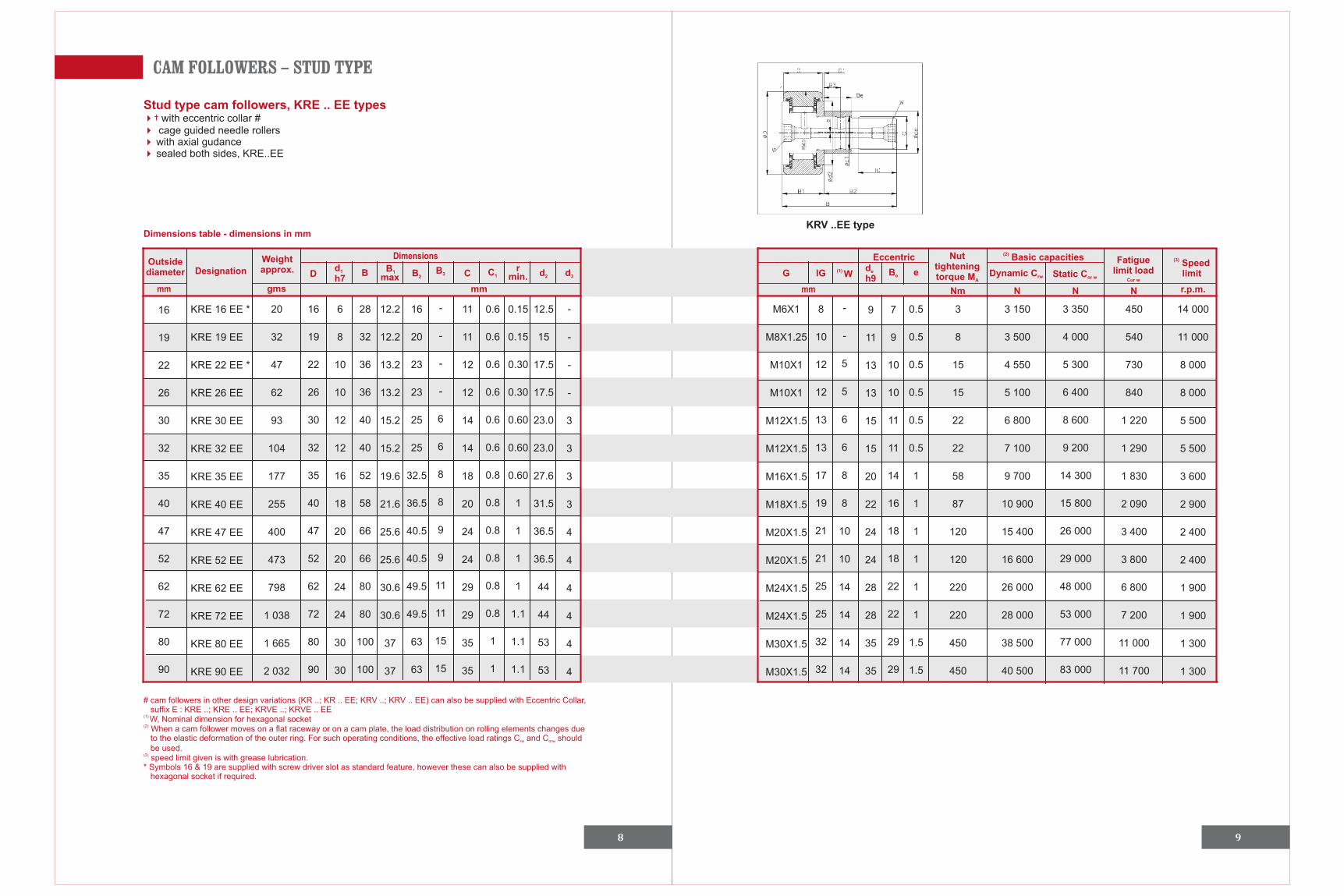
Stud type cam followers, KRE .. EE types4†444
with eccentric collar # cage guided needle rollers with axial gudance sealed both sides, KRE..EE
Dimensions table - dimensions in mm
mm
Designation
DimensionsOutsidediameter
Weight approx.
gms
Dd1
h7B
B 1
max
B2B 3 C C1
rmin. d2 d3 G
mm mm
lG (1) W
16
19
22
26
30
32
35
40
47
52
62
72
80
90
KRV ..EE type
# cam followers in other design variations (KR ..; KR .. EE; KRV ..; KRV .. EE) can also be supplied with Eccentric Collar, suffix E : KRE ..; KRE .. EE; KRVE ..; KRVE .. EE(1) W, Nominal dimension for hexagonal socket(2) When a cam follower moves on a flat raceway or on a cam plate, the load distribution on rolling elements changes due to the elastic deformation of the outer ring. For such operating conditions, the effective load ratings C and C shouldrw orw
be used.(3) speed limit given is with grease lubrication.* Symbols 16 & 19 are supplied with screw driver slot as standard feature, however these can also be supplied with hexagonal socket if required.
KRE 16 EE *
KRE 19 EE
KRE 22 EE *
KRE 26 EE
KRE 30 EE
KRE 32 EE
KRE 35 EE
KRE 40 EE
KRE 47 EE
KRE 52 EE
KRE 62 EE
KRE 72 EE
KRE 80 EE
KRE 90 EE
20
32
47
62
93
104
177
255
400
473
798
1 038
1 665
2 032
16
19
22
26
30
32
35
40
47
52
62
72
80
90
6
8
10
10
12
12
16
18
20
20
24
24
30
30
28
32
36
36
40
40
52
58
66
66
80
80
100
100
12.2
12.2
13.2
13.2
15.2
15.2
19.6
21.6
25.6
25.6
30.6
30.6
37
37
16
20
23
23
25
25
32.5
36.5
40.5
40.5
49.5
49.5
63
63
-
-
-
-
6
6
8
8
9
9
11
11
15
15
11
11
12
12
14
14
18
20
24
24
29
29
35
35
0.6
0.6
0.6
0.6
0.6
0.6
0.8
0.8
0.8
0.8
0.8
0.8
1
1
0.15
0.15
0.30
0.30
0.60
0.60
0.60
1
1
1
1
1.1
1.1
1.1
12.5
15
17.5
17.5
23.0
23.0
27.6
31.5
36.5
36.5
44
44
53
53
-
-
-
-
3
3
3
3
4
4
4
4
4
4
M6X1
M8X1.25
M10X1
M10X1
M12X1.5
M12X1.5
M16X1.5
M18X1.5
M20X1.5
M20X1.5
M24X1.5
M24X1.5
M30X1.5
M30X1.5
8
10
12
12
13
13
17
19
21
21
25
25
32
32
-
-
5
5
6
6
8
8
10
10
14
14
14
14
N N N
Nut tighteningtorque MA
(2) Basic capacities Fatiguelimit load
Cur w
(3) Speedlimit
Nm
Dynamic Crw Static Cor w
r.p.m.
9
11
13
13
15
15
20
22
24
24
28
28
35
35
7
9
10
10
11
11
14
16
18
18
22
22
29
29
Eccentricde
h9Be e
0.5
0.5
0.5
0.5
0.5
0.5
1
1
1
1
1
1
1.5
1.5
3
8
15
15
22
22
58
87
120
120
220
220
450
450
3 150
3 500
4 550
5 100
6 800
7 100
9 700
10 900
15 400
16 600
26 000
28 000
38 500
40 500
3 350
4 000
5 300
6 400
8 600
9 200
14 300
15 800
26 000
29 000
48 000
53 000
77 000
83 000
450
540
730
840
1 220
1 290
1 830
2 090
3 400
3 800
6 800
7 200
11 000
11 700
14 000
11 000
8 000
8 000
5 500
5 500
3 600
2 900
2 400
2 400
1 900
1 900
1 300
1 300

10
NOTES

11
NOTES

12
NOTES