cameras. lenses. photo scale. principles of aerial...
TRANSCRIPT

NRMT 2270, Photogrammetry/Remote Sensing
Lecture 4
Cameras. Lenses. Photo Scale. Principles of Aerial Photography. Principle and Conjugate Principal Points.
Vertical and Oblique Aerial photos. Stereo Viewing. Vertical Exaggeration.
Tomislav Sapic GIS Technologist
Faculty of Natural Resources Management Lakehead University
Cameras
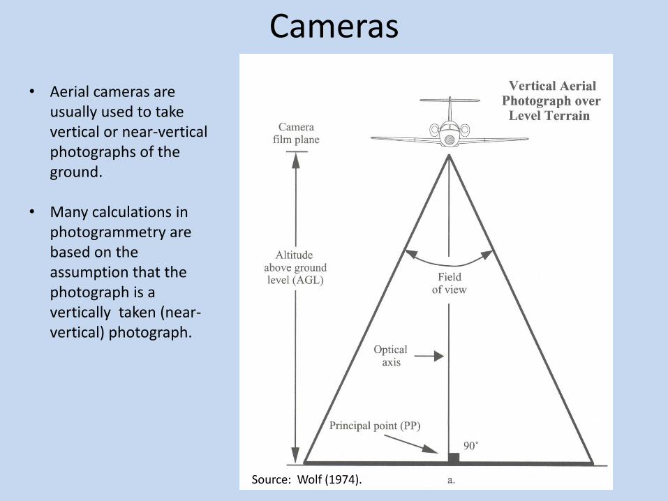
Source: Wolf (1974).
• Aerial cameras are usually used to take vertical or near-vertical photographs of the ground.
• Many calculations in photogrammetry are based on the assumption that the photograph is a vertically taken (near-vertical) photograph.

Camera and Eye Optics
Cameras Focal (Film) Plane: The plane of the film or sensor Focal Length: The distance from the rear nodal point of the lens to the film plane. • Professional aerial photo cameras usually have longer focal length lenses, e.g. 88 mm, 105 mm, 152 mm, 305 mm, etc.
Lens: Optical glass that gathers light rays from object points and brings them to focus at some distance on the opposite side of the lens. Aperture: The hole or the opening through which light is let through the lens and onto the film. Shutter: The device that lets the light to pass for a specific period of time.
Source: Jensen (2007).
Lenses
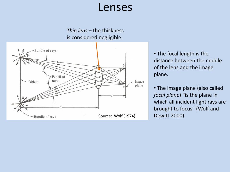
• The focal length is the distance between the middle of the lens and the image plane. • The image plane (also called focal plane) “is the plane in which all incident light rays are brought to focus” (Wolf and Dewitt 2000)
Thin lens – the thickness is considered negligible.
Source: Wolf (1974).

Lenses Thick lens – one thick lens or a combination of several thin lenses.
An aerial photo camera thick lens – Super Aviogon.
Incident node
Emergent node (rear nodal point)
• The focal length is the distance between the rear nodal point and the image plane. Source: Wolf (1974).
Source: Wolf (1974).

Lenses • The lens assembly is the most important part of the camera.
• The aerial camera lens on an aircraft is focused at infinity because aircrafts
usually fly at thousands of meters above the terrain.
• Lenses can have different angles of view, depending on the mission
requirements.
Camera Lens Angle of View
• Narrow lens: < 60⁰
• Normal lens: 60⁰ - 75⁰
• Wide-angle lens: 75⁰ - 100⁰
• Super-wide angle lens: > 100 ⁰
Source: Jensen (2007).
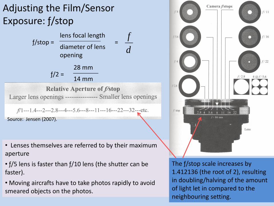
lens focal length
diameter of lens opening
= d
fƒ/stop =
Adjusting the Film/Sensor Exposure: ƒ/stop
ƒ/2 = 28 mm
14 mm
• Lenses themselves are referred to by their maximum aperture
• ƒ/5 lens is faster than ƒ/10 lens (the shutter can be faster).
• Moving aircrafts have to take photos rapidly to avoid smeared objects on the photos.
The ƒ/stop scale increases by 1.412136 (the root of 2), resulting in doubling/halving of the amount of light let in compared to the neighbouring setting.
Source: Jensen (2007).
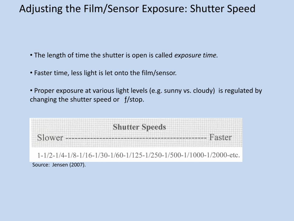
• The length of time the shutter is open is called exposure time. • Faster time, less light is let onto the film/sensor. • Proper exposure at various light levels (e.g. sunny vs. cloudy) is regulated by changing the shutter speed or ƒ/stop.
Adjusting the Film/Sensor Exposure: Shutter Speed
Source: Jensen (2007).

Aerial Analog Metric Camera
Source: Jensen (2007).

Film Annotation
• Aerial photos are taken in great numbers and in different conditions, requiring a system of their identification. • Aerial photos are also used for different measurements of the earth objects -- the geometry at the moment of taking the photo needs to be recorded and used during the measurements (e.g. fiducial marks recorded on films).

Aerial Digital Cameras
Two main arrays of detectors:
Linear – create seamless digital image strips.
Area – create separate, frame, digital images.
Two main imaging sensors:
Charge-coupled device (CCD)
Complimentary Metal Oxide Semiconductor (CMOS)
Source: Jensen (2007).

Aerial Digital Cameras
• Voltages (reflectance/radiance) captured by CCD or CMOS sensor detectors is converted to digital brightness values within the designed data depth (8 bit, or 11 bit, or 16 bit, etc.) and stored in image files (rasters).
• Depending on the number of detectors (pixels), aerial digital cameras are divided into small-format, medium-format, and large-format cameras.
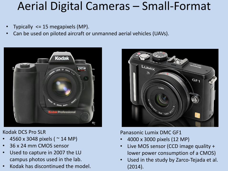
Aerial Digital Cameras – Small-Format
• Typically <= 15 megapixels (MP). • Can be used on piloted aircraft or unmanned aerial vehicles (UAVs).
Kodak DCS Pro SLR • 4560 x 3048 pixels ( ~ 14 MP) • 36 x 24 mm CMOS sensor • Used to capture in 2007 the LU
campus photos used in the lab. • Kodak has discontinued the model.
Panasonic Lumix DMC GF1 • 4000 x 3000 pixels (12 MP) • Live MOS sensor (CCD image quality +
lower power consumption of a CMOS) • Used in the study by Zarco-Tejada et al.
(2014).
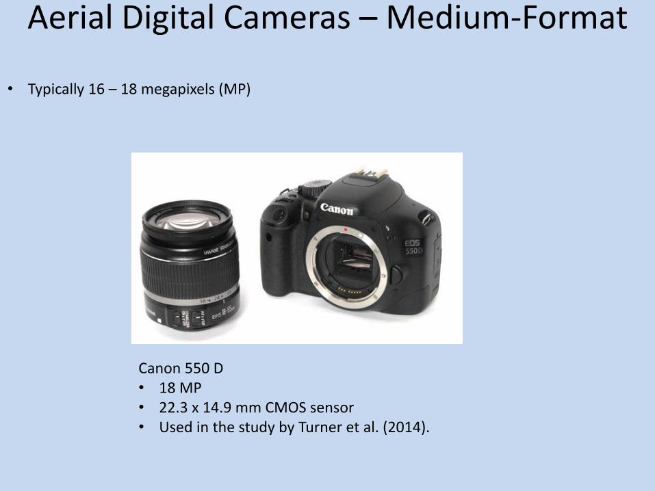
Aerial Digital Cameras – Medium-Format
• Typically 16 – 18 megapixels (MP)
Canon 550 D • 18 MP • 22.3 x 14.9 mm CMOS sensor • Used in the study by Turner et al. (2014).
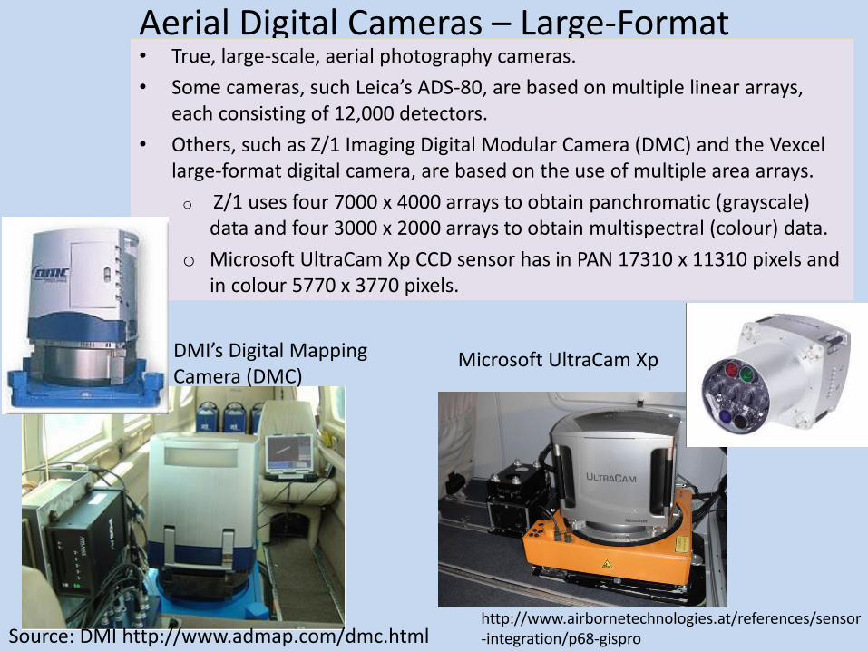
Aerial Digital Cameras – Large-Format • True, large-scale, aerial photography cameras.
• Some cameras, such Leica’s ADS-80, are based on multiple linear arrays, each consisting of 12,000 detectors.
• Others, such as Z/1 Imaging Digital Modular Camera (DMC) and the Vexcel large-format digital camera, are based on the use of multiple area arrays.
o Z/1 uses four 7000 x 4000 arrays to obtain panchromatic (grayscale) data and four 3000 x 2000 arrays to obtain multispectral (colour) data.
o Microsoft UltraCam Xp CCD sensor has in PAN 17310 x 11310 pixels and in colour 5770 x 3770 pixels.
DMI’s Digital Mapping Camera (DMC)
Source: DMI http://www.admap.com/dmc.html http://www.airbornetechnologies.at/references/sensor-integration/p68-gispro
Microsoft UltraCam Xp
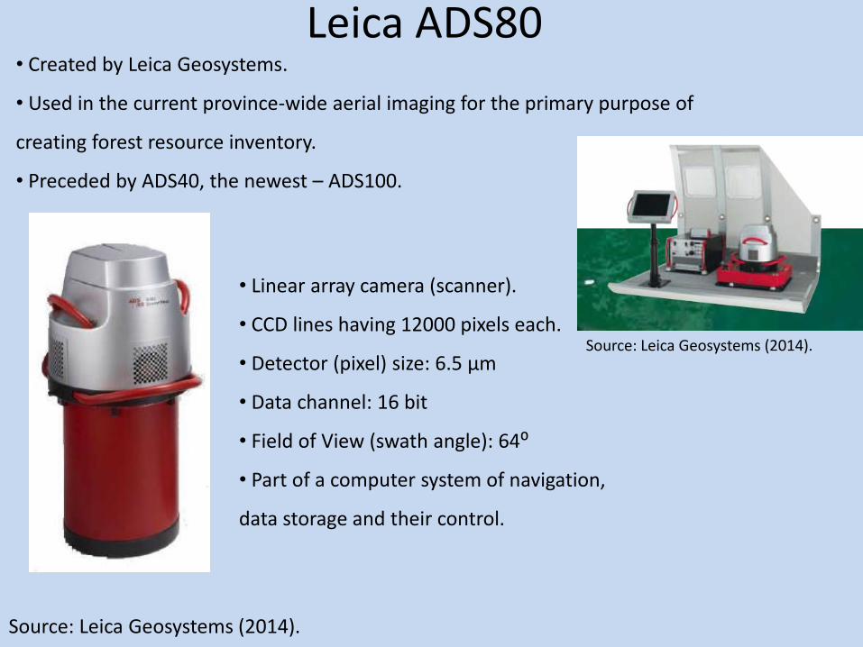
Leica ADS80 • Created by Leica Geosystems.
• Used in the current province-wide aerial imaging for the primary purpose of
creating forest resource inventory.
• Preceded by ADS40, the newest – ADS100.
• Linear array camera (scanner).
• CCD lines having 12000 pixels each.
• Detector (pixel) size: 6.5 μm
• Data channel: 16 bit
• Field of View (swath angle): 64⁰
• Part of a computer system of navigation,
data storage and their control.
Source: Leica Geosystems (2014).
Source: Leica Geosystems (2014).
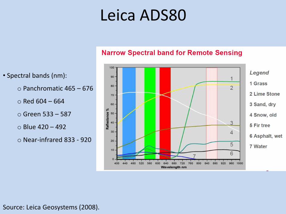
Leica ADS80
• Spectral bands (nm):
o Panchromatic 465 – 676
o Red 604 – 664
o Green 533 – 587
o Blue 420 – 492
o Near-infrared 833 - 920
Source: Leica Geosystems (2008).
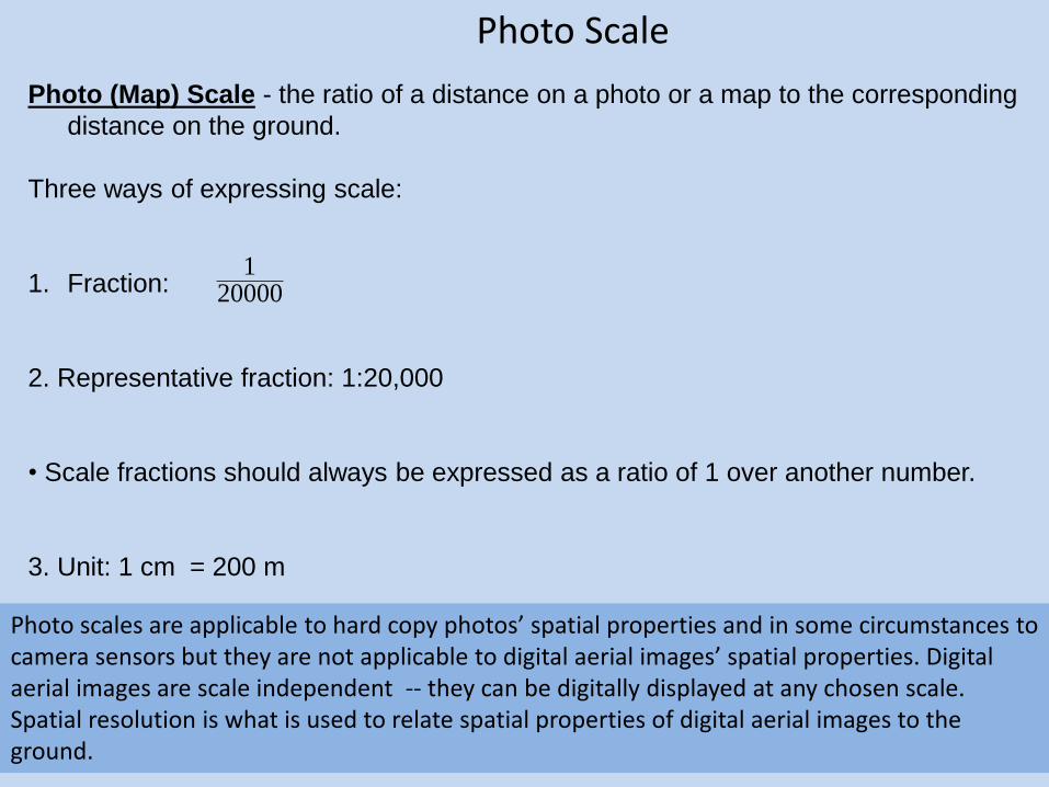
Photo (Map) Scale - the ratio of a distance on a photo or a map to the corresponding
distance on the ground.
Three ways of expressing scale:
1. Fraction:
2. Representative fraction: 1:20,000
• Scale fractions should always be expressed as a ratio of 1 over another number.
3. Unit: 1 cm = 200 m
200001
Photo Scale
Photo scales are applicable to hard copy photos’ spatial properties and in some circumstances to camera sensors but they are not applicable to digital aerial images’ spatial properties. Digital aerial images are scale independent -- they can be digitally displayed at any chosen scale. Spatial resolution is what is used to relate spatial properties of digital aerial images to the ground.

Photo Scale
20000
1
1750
0875.0
1750
75.8
m
m
m
cms
AB
ab
cetanDis_Ground
cetanDis_Photos
Example:
Source: Jensen (2007).

Photo Scale
Map Scale = 1:50,000
ScalexMapceDisMap
ceDisPhotos _
tan_
tan_
17157
1
9.17156
1
175000
2.10
50000
1
5.3
2.10 xsExample:

Photo Scale (Vertical Frame Photography)
height)(flying_Hlength)_(focalfS
20000
1
'10000
'5.0S
• The scale of a vertical photo is directly proportional to the camera focal length and inversely proportional to flying height above ground. • The focal length based calculation should be directly applied to only the photo printouts (positives) that are at a 1:1 scale versus their negative. Otherwise a scaling of the printout measures to the sensor (film frame) measures is required. Example:
Source: Wolf (1974).

Focal Length Based Photo Scale on Variable Terrain (Vertical Frame Photography)
avgh-HfSavg
ƒ = 105 mm = 0.105 m H = 4500 m asl h = 400 m h1 = 450 m h2 = 50 m havg= 300
Example:
40000
1300-4500
105.0 avgSSource: Wolf (1974).

Photo Scale (Vertical Frame Photography)
Camera sensor (CCD): 24 x 35 mm; Camera focal length: 105 mm. Flying height: 3120 m (GPS measured - a.s.l. ) Average terrain height: 440 m Photo printout: 193 x 290 mm.
25524
1
4403120
105.0
avgh-Hf)sensor(S
Photo (short side) / sensor (short side) = 193/24 = 8 Photo (long side) / sensor (long side) = 290/35 = 8
Photo scale = 3190
18
25524
1
• When it comes to digital photos, since the printouts are larger than the sensors that captured the photo, the focal length based calculation needs to be adjusted for this difference
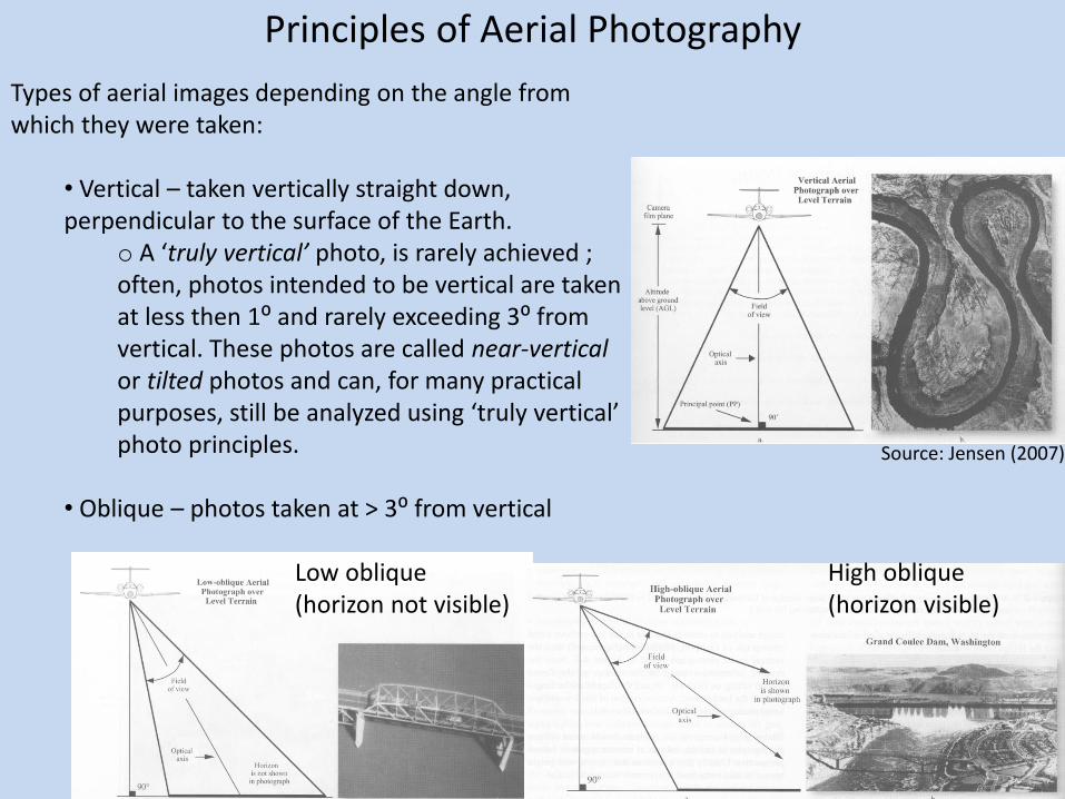
Principles of Aerial Photography
Types of aerial images depending on the angle from which they were taken:
• Vertical – taken vertically straight down, perpendicular to the surface of the Earth.
o A ‘truly vertical’ photo, is rarely achieved ; often, photos intended to be vertical are taken at less then 1⁰ and rarely exceeding 3⁰ from vertical. These photos are called near-vertical or tilted photos and can, for many practical purposes, still be analyzed using ‘truly vertical’ photo principles.
• Oblique – photos taken at > 3⁰ from vertical
Low oblique (horizon not visible)
High oblique (horizon visible)
Source: Jensen (2007).
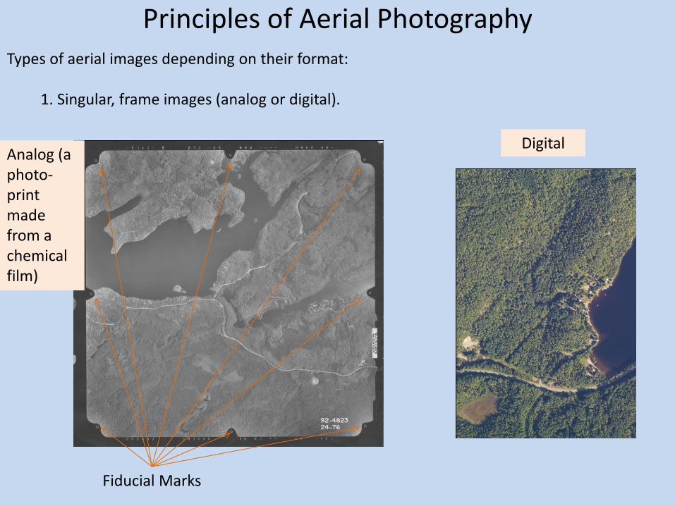
Principles of Aerial Photography Types of aerial images depending on their format:
1. Singular, frame images (analog or digital).
Analog (a photo-print made from a chemical film)
Fiducial Marks
Digital

Types of aerial images depending on their format:
2. Seamless image strip (digital).
Image strip GIS layer
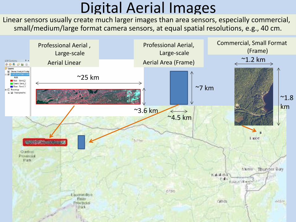
Commercial, Small Format (Frame)
Digital Aerial Images Linear sensors usually create much larger images than area sensors, especially commercial,
small/medium/large format camera sensors, at equal spatial resolutions, e.g., 40 cm.
~25 km
~3.6 km
~1.8 km
~1.2 km
~7 km
~4.5 km
Professional Aerial , Large-scale
Aerial Linear
Professional Aerial, Large-scale
Aerial Area (Frame)
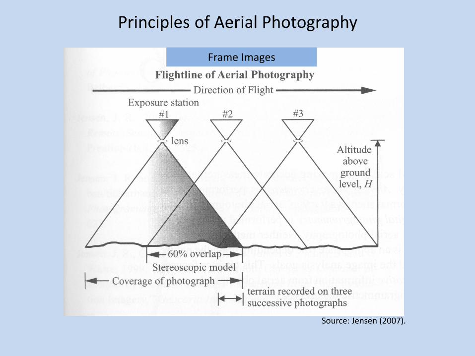
Principles of Aerial Photography
Source: Jensen (2007).
Frame Images

Principal Points (PPs), Conjugate Principal Points (CPPs) and Lines of Flight (Flight Lines) (Frame Images)
Source: Jensen (2007).
• Fiducial marks are part of the image coordinate system, formed by horizontally and vertically connecting the opposing fiducial marks and creating the x and y image axis, respectively
• The intersection of the two axes is called principal point.
• The principal point at the intersection of the x and y axes is through the manufacturing and calibration of the camera made very close to the true principal , which is the point in the image plane where a line from the rear nodal point of the lens, perpendicular to the image plane, intersects the image plane. (Wolf and Dewitt 2000).
• Contrary to the shown, the flight line rarely coincides with the image x axis.

CPP77 PP76
Flight Line
PP77 CPP76
Flight Line
Principal Points (PPs), Conjugate Principal Points (CPPs) and Flight Lines (Frame Images)
• A Conjugate Principal Point (CPP) on a photo is the location of the Principal Point on an adjacent, end-overlapping, photo. The CPP location needs to be identified stereoscopically to account for radial displacement. In other words, the CPP shows over which point the camera (the plane) was positioned when the adjacent photo was taken. That means that the line connecting the PP and a CPP on a photo represents the flight line over the area (terrain) shown in the photo.

Stereoscopic Vision
• When focusing with two eyes on an object, a parallactic angle is formed. • The closer the object is to the eyes the wider the parallactic angle is. • The brain has learned to associate distances DA and DB with parallactic angles Øa and Øb,
respectively, and gives the viewer the visual and mental impression that A is closer than B.
• Looking out farther away makes differences in parallactic angles more and more subtle, to the point of them being undistinguishable to an average human adult at around 1000 m. • The eye base would need to stretch out to a meter or hundreds of meters, creating hyperstereoscopy.
• Obviously, biologically this is impossible, but can be substituted by using a model, i.e. stereo (aerial) photos.
Source: Jensen (2007).
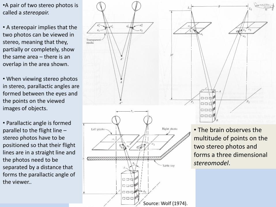
•A pair of two stereo photos is called a stereopair. • A stereopair implies that the two photos can be viewed in stereo, meaning that they, partially or completely, show the same area – there is an overlap in the area shown. • When viewing stereo photos in stereo, parallactic angles are formed between the eyes and the points on the viewed images of objects. • Parallactic angle is formed parallel to the flight line – stereo photos have to be positioned so that their flight lines are in a straight line and the photos need to be separated by a distance that forms the parallactic angle of the viewer..
• The brain observes the multitude of points on the two stereo photos and forms a three dimensional stereomodel.
Source: Wolf (1974).
Pseudostereo
• When the two photos are reversed and the left eye is viewing the right photo and the right eye the left photo, pseudostereo is created – the field of view 3D depth is reversed: e.g., hills look like valleys and valleys like hills.

• Once a stereopair is created what is left to do is to place the stereo photos/images in a proper position and restrict the left eye to seeing the left photo/image only and the right eye to seeing the right photo/image only. • This visual separation is achieved through different means, including using stereoscopes, anaglyph glasses, polaroid glasses, and shutter glasses.
Lens/pocket sterescope Source: Jensen (2007).

Anaglyph glasses
cyan red
Anaglyph Glasses
• The left image (from the viewer’s perspective) is displayed in red and the right in cyan. The left eye, red, filter on the glasses, absorbs cyan and lets through red and the right eye, cyan, filter, absorbs red and lets through only cyan.
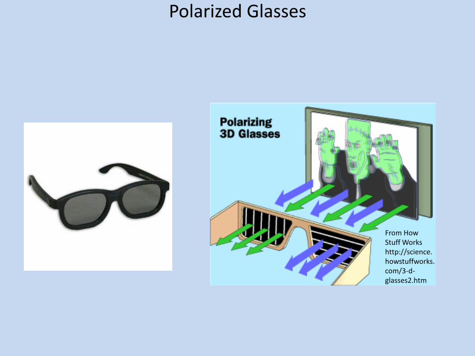
Polarized Glasses
From How Stuff Works http://science.howstuffworks.com/3-d-glasses2.htm

Shutter glasses
Picture from http://www.mnr.gov.on.ca/en/Business/Forests/2ColumnSubPage/199556.html
Computer Generated Stereo Display With Shutter Glasses
Emitter • The computer, through the graphics card, shows the left and the right image on the screen and alternately turns them on and off ~60 times/sec (Hz) each. • The emitter is connected to the computer graphics card and syncs through infrared the shutter glasses with the image displays - the left lens on the glasses opens up when the left image is displayed and closes when the right image is displayed; the opposite applies to the right lens.
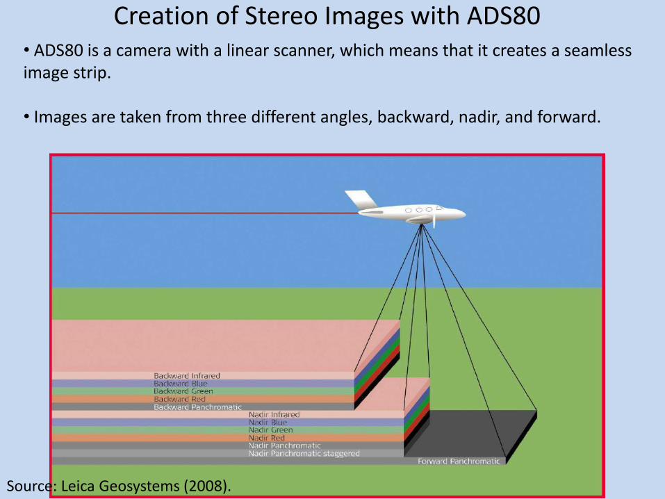
Creation of Stereo Images with ADS80 • ADS80 is a camera with a linear scanner, which means that it creates a seamless image strip. • Images are taken from three different angles, backward, nadir, and forward.
Source: Leica Geosystems (2008).
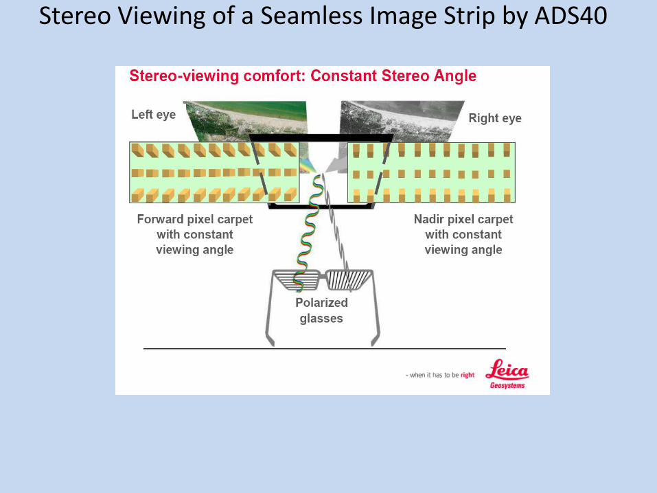
Stereo Viewing of a Seamless Image Strip by ADS40

From: http://www.photogrammetry.ethz.ch/summerschool/pdf/03_Gruen_Pateraki_DAC.pdf
Forward
Nadir
Backward
Seamless Image Strip Triplet (Forward, Nadir, and Backward View)
Direction of flight
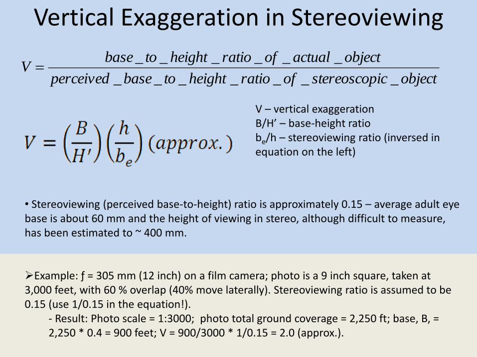
Vertical Exaggeration in Stereoviewing
V – vertical exaggeration B/H’ – base-height ratio be/h – stereoviewing ratio (inversed in equation on the left)
• Stereoviewing (perceived base-to-height) ratio is approximately 0.15 – average adult eye base is about 60 mm and the height of viewing in stereo, although difficult to measure, has been estimated to ~ 400 mm. Example: ƒ = 305 mm (12 inch) on a film camera; photo is a 9 inch square, taken at 3,000 feet, with 60 % overlap (40% move laterally). Stereoviewing ratio is assumed to be 0.15 (use 1/0.15 in the equation!).
- Result: Photo scale = 1:3000; photo total ground coverage = 2,250 ft; base, B, = 2,250 * 0.4 = 900 feet; V = 900/3000 * 1/0.15 = 2.0 (approx.).
objecticstereoscopofratioheighttobaseperceived
objectactualofratioheighttobaseV
_______
______
References:
Jensen., J. R. 2007. Remote Sensing of the Environment: An Earth Resource Perspective. Pearson Prentice Hall.
Leica Geosystems. 2008. Leica - 3rd Generation Airborne Digital Sensors: Features/Benefits for Remote Sensing
& Environmental Application.
http://www.google.com/url?sa=t&rct=j&q=&esrc=s&source=web&cd=1&ved=0CCoQFjAA&url=http%3A%
2F%2Fmars.jrc.ec.europa.eu%2Fmars%2Fcontent%2Fdownload%2F1176%2F6943%2Ffile%2FT1_Rohrbac
h_Rohrbach-AirborneSensors-3rd_Leica.pdf&ei=35NkUvrqMa-
E2gWWqoCwBw&usg=AFQjCNFxEdk3vWVOSM_CAXFELGDLjceZNg&bvm=bv.54934254,d.b2I&cad=rja.
Leica Geosystems. 2014. http://www.leica-
geosystems.com/downloads123/zz/airborne/ads80/brochures/ADS80_Brochure_en.pdf January 20,
2014.
Turner, D., A. Lucieer and L. Wallace. 2014. Direct georeferencing of ultrahigh-resolution UAV imagery. IEEE
Transactions on Geoscience and Remote Sensing. 52(5).
Vexcel. 2008. UltraCam-XP Technical Specifications.
White, R. 2006. How Computers Work. QUE, Indianapolis, IN, USA.
Wolf, P. R. 1974. Elements of Photogrammetry. McGraw-Hill, Inc.
Wolf, P. R. and Dewitt B. A. 2000 Elements of Photogrammetry with Applications in GIS. The McGraw-Hill
companies, Inc. 3rd Edition.
Zarco-Tejada, P.J., R. Diaz-Varela, V. Angileri and P. Loudjani. 2014. Tree height quantification using very high
resolution imagery acquired from an unmanned aerial vehicle (UAV) and automatic 3D photo-
rconstruction methods. European Journal of Agronomy. 55:89-99.