can steam turbine - enerji projeleri
TRANSCRIPT

CAN
STEAM
TURBINE
Training related to ST
performance
13 July 2017
| 2
INTRODUCTION - GOALS
▪ Steam turbine
Main principles
Technology
Focus on performances
Efficiency
• ST Terminal conditions
• Where losses could come from?
▪ Degradations
Illustrations on main degradation process
How to monitor?
How to prevent or maintain?
Comments when there are in the specific case of Can steam turbine
EDF-CIT / steam turbine / 13/07/2017

| 3
PART 1
PRINCIPLES
PERFORMANCES
EDF-CIT / steam turbine / 13/07/2017

| 4EDF-CIT / steam turbine / 13/07/2017
STEAM TURBINE PRINCIPLES
ST IN THE WATER/STEAM CYCLE

| 5
STEAM TURBINE PRINCIPLES
▪ To convert thermal power into
mechanical power
• Efficiency : nearby 90%
• Mechanical losses : at
bearing (by friction) less than
0.5%
• Generator loss: nearby 1%
EDF-CIT / steam turbine / 13/07/2017

| 6EDF-CIT / steam turbine / 13/07/2017
6
THERMODYNAMIC CONVERSION IN A SINGLE
STAGE
The thermodynamic 1st principle application to a steam turbine
single stage (static part 0→1 + wheel 1 →2) is : ( )02
2
=+=+ qwv
ddh t
Consequently, the energy conversion is : 02
2
00
2
22
22ttt hh
vh
vhw −=
+−
+=
This formula could be figured as followed in the Mollier (H versus S) diagram:
h
s
t : mechanical
work
v²2 /2 : remaining
velocity
v²0 /20
1
2
1is
2'is
Losses in the static
part
Losses in the wheel
P0
P1
P2
dP=0
2is
Available enthalpy
drop
v²1 /2
| 7EDF-CIT / steam turbine / 13/07/2017
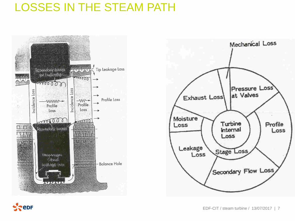
LOSSES IN THE STEAM PATH

| 8EDF-CIT / steam turbine / 13/07/2017
FLOW CALCULATION IN A MULTISTAGE
TURBINE
An empirical formula, very simple and often used, is the Stodola relationship giving the mass
flow function of inlet and exhaust pressure for a given ST rotation speed
i
ei
T
PPStM
22 −=
St : Stodola’s coefficient which depends on rotation speed and
steam turbine geometry.
Pi, Pe : inlet pressure, exhaust pressure
Ti : steam inlet temperature
Generally, Pe >> Ps, the steam turbine mass flow is therefore nearly proportional to inlet pressure
PePs
M

| 9
STEAM TURBINE TECHNOLOGY
▪ Steam turbine supplied by Alstom
Impulse type
Combined HP / IP turbine
LP turbine, single flow
Last LP stage blades : fir-tree root, with snubber
▪ Some dates
Commissioned in 2006
End of 2016 : 77000 OH, 90000 EOH
LP turbine maintenance in 2015
1st major overhaul for HIP turbine in 2018
EDF-CIT / steam turbine / 13/07/2017

| 10Titre de la présentation | mm/aaaaEDF-CIT / steam turbine / 13/07/2017

| 11EDF-CIT / steam turbine / 13/07/2017

| 12EDF-CIT / steam turbine / 13/07/2017
| 13
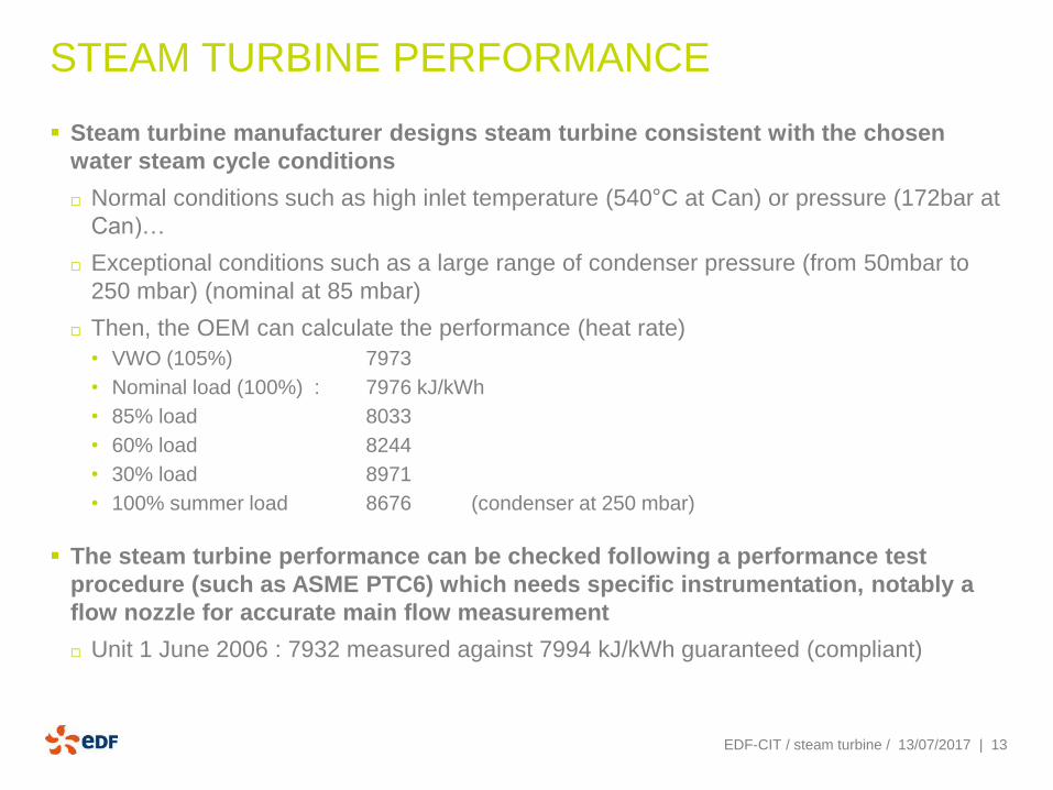
STEAM TURBINE PERFORMANCE
▪ Steam turbine manufacturer designs steam turbine consistent with the chosen
water steam cycle conditions
Normal conditions such as high inlet temperature (540°C at Can) or pressure (172bar at
Can)…
Exceptional conditions such as a large range of condenser pressure (from 50mbar to
250 mbar) (nominal at 85 mbar)
Then, the OEM can calculate the performance (heat rate)
• VWO (105%) 7973
• Nominal load (100%) : 7976 kJ/kWh
• 85% load 8033
• 60% load 8244
• 30% load 8971
• 100% summer load 8676 (condenser at 250 mbar)
▪ The steam turbine performance can be checked following a performance test
procedure (such as ASME PTC6) which needs specific instrumentation, notably a
flow nozzle for accurate main flow measurement
Unit 1 June 2006 : 7932 measured against 7994 kJ/kWh guaranteed (compliant)
EDF-CIT / steam turbine / 13/07/2017

| 14
IMPACT OF THE LAST STAGE BLADE CHOICE
▪ Example
Blade length approx 800mm 800mm 1100mm
Exhaust area approx 6 m² 2 x 6m² 10m²
Output at 60 mbar -4% +1.25% ref
Output at 200 mbar +3% 0 ref
Output at 250 mbar +4% ref impossible
EDF-CIT / steam turbine / 13/07/2017

| 15
IMPACT OF THE TERMINAL CONDITIONS
▪ Correction curves…. Can
HP Pressure -0.20%HR pour +10 bar
HP Temperature -0.30%HR when +10 °C
IP Pressure (reheat pressure drop) +0.08%HR when +1%reheat pressure drop
IP Temperature -0.27%HR when +10 °C
Condenser pressure +0.56%HR when +10mbar
EDF-CIT / steam turbine / 13/07/2017

| 16EDF-CIT / steam turbine / 13/07/2017
summer
nominal

| 17
▪ Order of magnitude
EDF-CIT / steam turbine / 13/07/2017

| 18EDF-CIT / steam turbine / 13/07/2017
With time, steam turbine performance is
deteriorating :
- Operating Conditions : notably steam
quality
- SPE or FOD
-Vibration behavior
-…
“A survey of 31 steam path audits
indicated average section efficiency
deterioration was 12.5% for the HP, 9.1%
for the IP, and 3% for the LP.
Most of the total loss in these turbines
was caused by either leakage (about
50% of the total) or surface roughness
(about 36% of the total).”

| 19
ENTHALPY DROP MEASUREMENT SEE INFORMATION SYSTEM (CNK 00 M OVE --- ER 101B) - PAGE 21
▪ HP Efficiency :
Hinlet – Hexhaust
---------------------------
Hinlet- Hexhaust,isentropic
EDF-CIT / steam turbine / 13/07/2017
Expected :
Design 86.4%
Perf test 83%
| 20
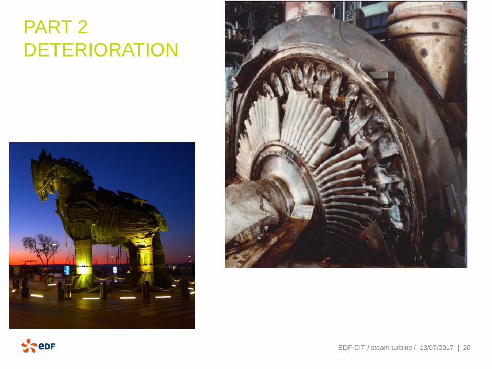
PART 2
DETERIORATION
EDF-CIT / steam turbine / 13/07/2017

| 21
STEAM TURBINE DAMAGES AFFECTING THE
STEAM PATH COMPONENTS
▪ Solid particle erosion at HP and IP
▪ Foreign object damages
▪ Deposits
▪ Creep and creep fatigue : high temperature
▪ Corrosion fatigue (mainly LP blades)
▪ Fatigue
▪ Stress corrosion : LP at disk and blade root
▪ General Corrosion : where carbon steel
▪ Pitting corrosion
▪ Fretting
▪ Moisture effects :
Erosion (mainly in LP section) … max acceptable 12%
▪ Water induction
▪ Vibration
▪ Rubbing
EDF-CIT / steam turbine / 13/07/2017

| 22
SOLID PARTICLE EROSION (SPE) AT HP AND IP
FOREIGN OBJECT DAMAGES (FOD)

| 23
SPE
▪ SPE is caused by oxide scales exfoliates from boiler
▪ Among other effects, SPE causes :
Damages of blades and diaphragms
Increase in surface roughness
Deterioration of seal strips (increase of clearance)
Then could involve significant reduction in turbine efficiency
▪ How to monitor
1st wheel pressure versus flow monitoring
Enthalpy drop test
Boroscopic inspection
▪ How to prevent
Bypass operation at start-up
Boiler chemical cleaning
Fine mesh at main valves (only for short period…)
EDF-CIT / steam turbine / 13/07/2017
| 24
DEPOSITS
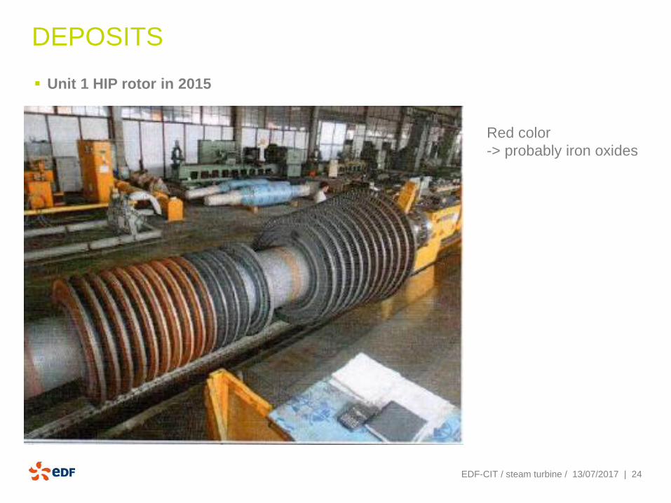
▪ Unit 1 HIP rotor in 2015
EDF-CIT / steam turbine / 13/07/2017
Red color
-> probably iron oxides

| 25
CAN FEEDBACK
▪ Unit 1: In 2007, the unit 1 was no more able to reach its full capacity. Indeed, to
accept the steam flow rate, the pressure at turbine inlet has notably increase,
showing that the steam turbine swallowing capacity had reduced.
▪ Decision was taken to open the HP/IP module: deposits were observed in large
quantity in the steam path (up to 2mm thick on the blades)
Mainly on stages HP 3 to 5 then decreasing along the others HP stages
Mainly on stage IP 6 then decreasing along the others HP stages
▪ Seals strips were also found deteriorated.
▪ The main suspected root cause was operation with bad steam quality during
commissioning and first months of operation before COD.
▪ The taken measures included:
Steam path cleaning (on damages seen on blades)
Gland packing replacement
And also several upgrade in operation procedure (notably of boiler one)
▪EDF-CIT / steam turbine / 13/07/2017
| 26
DEPOSITS
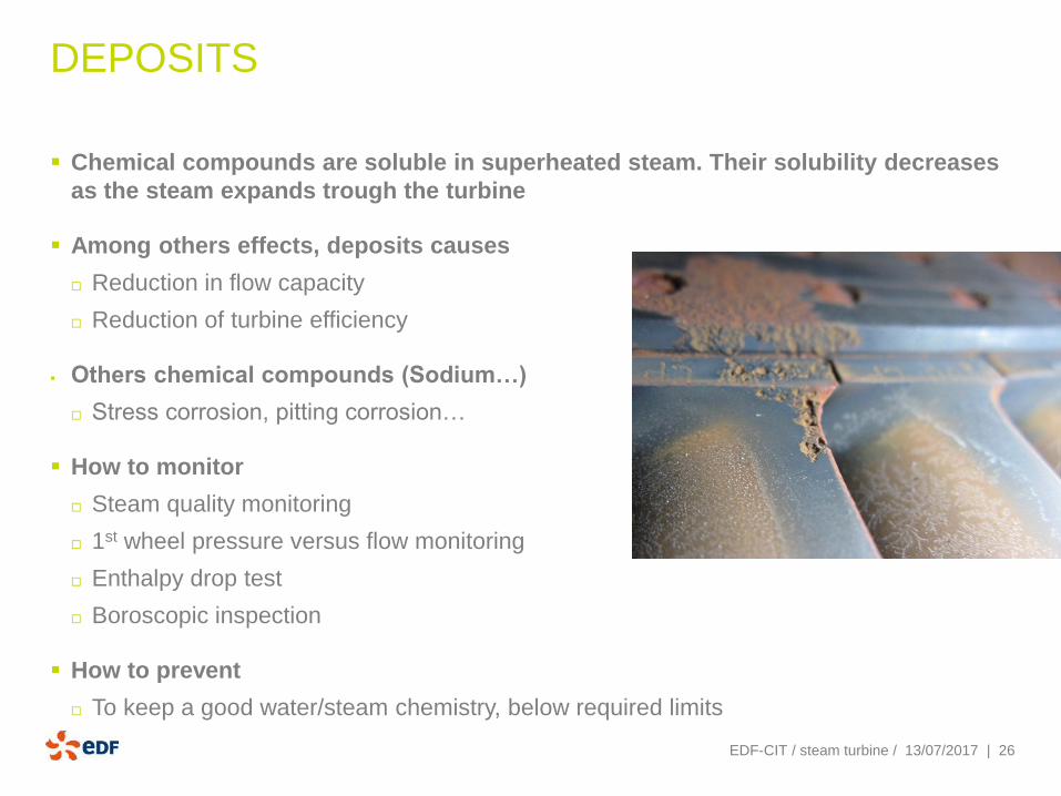
▪ Chemical compounds are soluble in superheated steam. Their solubility decreases
as the steam expands trough the turbine
▪ Among others effects, deposits causes
Reduction in flow capacity
Reduction of turbine efficiency
▪ Others chemical compounds (Sodium…)
Stress corrosion, pitting corrosion…
▪ How to monitor
Steam quality monitoring
1st wheel pressure versus flow monitoring
Enthalpy drop test
Boroscopic inspection
▪ How to prevent
To keep a good water/steam chemistry, below required limits
EDF-CIT / steam turbine / 13/07/2017

| 27
STEAM QUALITY
▪ Required at CAN (ST operating manual)
EDF-CIT / steam turbine / 13/07/2017

| 28EDF-CIT / steam turbine / 13/07/2017
STEAM QUALITY

| 29
RECOMMENDATIONS
▪ Monitoring
Steam path pollution is a concern since the commissioning: we recommend to perform a
performance monitoring.
At least, an annual “enthalpy drop test” for HP and IP turbine is simple to implement and could give a
could view on performance deterioration
▪ Steam quality
Steam quality is very important to keep, especially at start-up
After shutdown period, don’t hesitate to operate on bypass for a while
▪ Boiler cleanliness
To be checked (see with boiler specialist)
Separator to be inspected (to control that there is no bypass of the separator and that priming is very
low)
▪ Unit 2 HIP turbine cleaning
To plan HIP major maintenance as soon as possible (planned in 2018 according OEM maintenance
program)
EDF-CIT / steam turbine / 13/07/2017

| 30
MAIN VALVES DYSFUNCTION
▪ Currently, a IP stop valve of the unit 1 shows a dysfunction (closing slowing down
for the last 8% of the closing). A hydraulic problem is suspected, still on-going.
▪ These valves are very important for the safety (stop valves) and the availability of
the plant.
▪ Our recommendations:
▪ To solve the pending issues as soon as possible
▪ To continue regular test and maintenance based upon OEM recommendation. We
recommend not to change these test and maintenance periodicity without a full
study (FMEA with feedback from the plant)
EDF-CIT / steam turbine / 13/07/2017

| 31
MOISTURE EFFECTS
▪ Erosion is caused by water droplet present in the
last LP stages
▪ Detached pieces of eroded blades could impact
others LP blades
or condenser tubes
▪ Erosion could locally weaken blade, wire or snubber
resistance and increase risk of blade cracking
EDF-CIT / steam turbine / 13/07/2017
Leading
edge
Condenser
tubes
burst

| 32
FATIGUE IN LP BLADES
▪ Fatigue in LP turbine blade is one of the most common causes of steam turbine
catastrophic failures (with fire and overspeed)
EDF-CIT / steam turbine / 13/07/2017
Stresses at blade feet are
large for these long blade
Many scenario for failure are
possible
For instance, cracking could
be initiated by low cycle
fatigue and propagated by
high cycle fatigue
Initiation could be also from
stress corrosion, erosion,
pitting corrosion…
Unsteady flow, turbulent
wakes, flutter are at the
origin of strong excitation

| 33
OUR RECOMMENDATION
▪ These LP turbines are mainly in good shape.
Our recommendations:
▪ To continue regular maintenance based upon OEM recommendation. Considering
summer conditions in Can, the LP blades should be strongly “shaked” and it is
critical to inspect them regularly.
▪
EDF-CIT / steam turbine / 13/07/2017
| 34
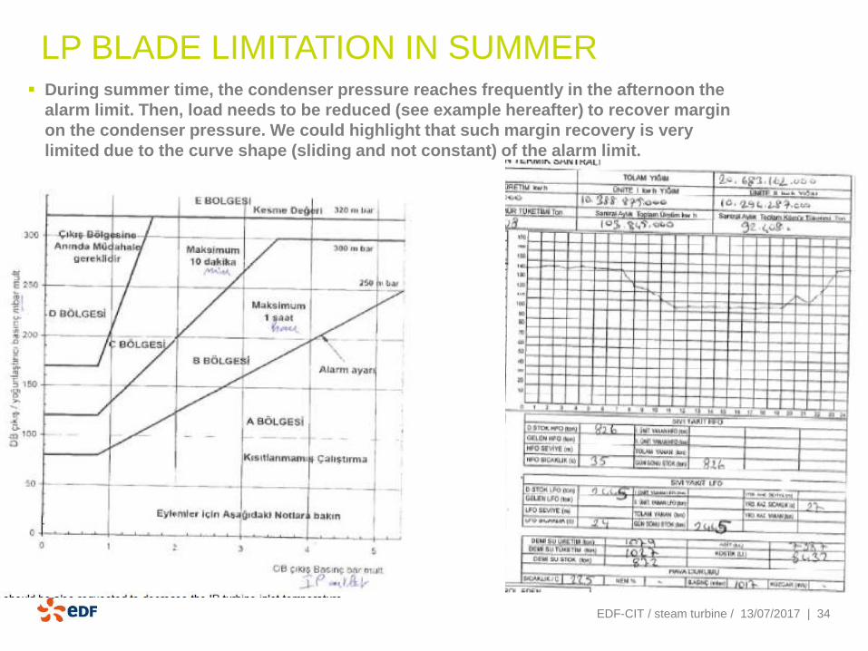
LP BLADE LIMITATION IN SUMMER ▪ During summer time, the condenser pressure reaches frequently in the afternoon the
alarm limit. Then, load needs to be reduced (see example hereafter) to recover margin
on the condenser pressure. We could highlight that such margin recovery is very
limited due to the curve shape (sliding and not constant) of the alarm limit.
EDF-CIT / steam turbine / 13/07/2017

| 35
OUR RECOMMENDATION
In addition of the power capacity decrease, there is also a strong efficiency reduction.
Our recommendations:
▪ Main cooling system
To limit the condenser pressure increase, we recommend preserving the cooling system
performance (cooling tower performance). That means regular monitoring of the fouling, regular
cleaning….
If possible, improvement of cooling system: Can Power plant has a project to add a new small
cooling tower. Providing there is no issue with circulating pumps operation (no vibration with this new
operating point), this project will bring useful margin for the summer operation of the LP turbine.
▪ Steam turbine:
The limitation (alarm threshold) comes from the last stage blade. The manufacturer could provide
alternative LP blades with higher limits but with bad consequences on all over the year performance
and above all, these alternative blades have larger roots which should need the LP rotor
replacement.
A monitoring of any air ingress and if any, a research of its origin and then repair
▪
EDF-CIT / steam turbine / 13/07/2017
| 36
LONG TERM DETERIORATION
Stress monitoring : This system, available is not currently used.
Our recommendations
▪ The power plant, becoming older, has this system available to regularly check its
lifetime consumption related to its normal or exceptional operation procedure.
▪ That may help
To evaluate lifetime consumption related to creep and fatigue damages of high
temperature component
To identify which operation case is responsible for lifetime consumption
To assess the impact of a new kind of operation (change in cold start-up number…) or
others
EDF-CIT / steam turbine / 13/07/2017

| 37
VIBRATIONS / RUBBING▪ Vibrations
They depends on
• Shafts line alignment… in case of house bearing level change, coupling shift
• Bearings behavior… in case of oil quality change or internal clearance
modification…
• Unbalance… in case of light rubbing (thermal), mechanical change
▪ Rubbing in either axial or radial directions depending on the cause
Can be caused by
• Differential expansion
• Sliding feet or keys seizing
• Creep (high temperature parts)
• Overheating by windage
Rubbing manifests vibrations
▪ On a performance point of view, vibrations and rubbing could deteriorate
interstage sealing as well as shaft end gland packing
Increasing clearances and so leakage losses
▪ How to monitor : vibration monitoring + analyser to have diagnostic
EDF-CIT / steam turbine / 13/07/2017
Light rubbing due
to blade creep

| 38EDF-CIT / steam turbine / 13/07/2017
GLAND STEAM SYSTEM
We could suggest performing flow
measurement at gland packing exhaust : That
will help in the assessment of leakage from
valves stem and from gland packing and so
far to appreciate their degradation.
Another simple criteria for this assessment is
to follow at which load the auxiliary steam
supply valve closed (when the gland steam
system is becoming self sufficient) : Higher the
load, worst the leakages from stems and HP
packing are.

teşekkürMERCI
| 40EDF-CIT / steam turbine / 13/07/2017
LOSSES IN BLADES
1. AERODYNAMIC LOSSES
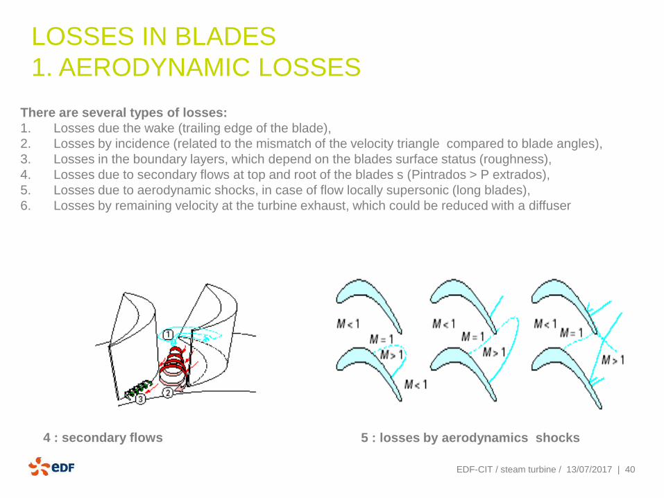
There are several types of losses:
1. Losses due the wake (trailing edge of the blade),
2. Losses by incidence (related to the mismatch of the velocity triangle compared to blade angles),
3. Losses in the boundary layers, which depend on the blades surface status (roughness),
4. Losses due to secondary flows at top and root of the blades s (Pintrados > P extrados),
5. Losses due to aerodynamic shocks, in case of flow locally supersonic (long blades),
6. Losses by remaining velocity at the turbine exhaust, which could be reduced with a diffuser
4 : secondary flows 5 : losses by aerodynamics shocks

| 41EDF-CIT / steam turbine / 13/07/2017
LOSSES IN THE BLADES
2. MOISTURE
The wet steam expansion creates water droplet by condensation. These droplets are centrifuged in
the wheel. By the way, this water flow : :
❑ doesn’t produce any work (i.e efficiency loss)),
❑ results in an erosion phenomenon of the blades and inner casing.
We could consider that 1% wetness in the steam decreases the stage efficiency by 1% (Bauman’s
rule) . Moreover, other steam expansion shall not go beyond 10-12% wetness (or 14-15% for half speed
turbine).

| 42EDF-CIT / steam turbine / 13/07/2017
LOSSES IN THE BLADES
3. LOSSES BY LEAKAGE
These losses are related to sealing between :
1. the fixed blades (nozzles, diaphragms) and shaft,
2. the moving blades shroud and the inner casing of the steam turbine.
These losses are proportional to the shaft diameter or inner casing diameter .
To reduce theses leakages, the manufacturer installs sealing which reduce the leakage flow. Moreover, it
could be beneficial to reduce the shaft diameter or to avoid small blades which have a relative loss larger .
Labyrinth seals at moving
blades