can you hear me now (final submitted to gastech 15) - kbr white papers/kbr... ·...
TRANSCRIPT

Page 1
GasTech 2015
Can You Hear Me Now? The Necessity for Noise Control in
LNG Liquefaction Plants
Jim Cowling – Chief Technology Engineer Noise & Vibration Sonia PG Sonnier – Senior Noise & Vibration Specialist, KBR, Houston, Texas
KBR, 601 Jefferson Street, Houston, TX 77002 USA
Introduction
Every new LNG export facility, irrespective of where it is to be built in the world, requires some degree of environmental impact assessment administered by the local and/or national legislating authorities. In addition, financial institutions involved in the project may also impose environmental requirements and restrictions. Noise, with in-‐plant noise affecting the plant operators and residential community receptors close to the plant, is one of the environmental issues that must be evaluated and controlled for any LNG project.
The key theme for this paper is; the earlier the noise control issues facing a project can be identified, addressed and resolved, the better the outcome for the project. That is outcome measured in the context of compliance with applicable noise limits, minimizing the environmental noise impact, providing a safe and manageable in-‐plant noise environment for the plant operators and minimizing the economic and schedule impact on the project. Contingent on this need to identify the noise control issues early is a need to accurately model and predict the plant noise levels utilizing field verified equipment noise levels and proven reference LNG plant noise models.
A hypothetical case study will be examined for a typical 10 Mt/a facility that will highlight the noise control analysis and noise control decisions that need to be addressed during the Front-‐End Engineering Design (FEED) phase of a project. The goal is to emphasize the importance of these critical noise control questions early in the project. This will allow the project to move forward with a feasible and practical Engineering, Procurement & Construction (EPC) Noise Control Basis of Design that is consistent with defined noise limits and environmental impact requirements and includes all operational, safety and economic considerations.
LNG Plant Noise Modeling
Effective and accurate plant noise modeling and prediction is critical for the successful noise control design for an LNG project. KBR experience has shown that LNG plant noise modeling must be based on a solid foundation of field verified equipment and piping noise data together with proven field verified LNG plant noise models[1]. Nothing gives more credibility in front of the plant owner than the statement “I know how noisy this piece of equipment is because I’ve measured one just like it in the field” and nothing can provide a better footing for the noise control design of an LNG facility. But, of course, that statement requires a significant amount of effort gathering good noise data in the field from a range LNG plants. KBR has been gathering field noise data from early LNG plants in Malaysia and Australia through the more recent LNG developments in Nigeria, Egypt and Algeria. The noise levels on KBR’s most recent LNG plant startup were in almost perfect agreement with those predicted from the plant noise model, again demonstrating the value and accuracy of modeling based on reliable field verified noise data.
Many LNG plant Environmental Impact Assessment (EIA) reports and preliminary noise reports exist that provide noise predictions based on suspect or poorly interpreted vendor data that leads to a noise control basis of design that is simply incorrect. These preliminary reports lead the Owner and engineering contractor project management teams in to a false sense of security that everything is fine on the noise front; when the problems to be identified late in a project, or even worse after startup, corrective action is difficult, costly and time consuming.

Page 2
It is important to remember that all new LNG plants have requirements, both legislative and contractual, for formal post-‐startup noise acceptance tests, often to be performed by independent third parties. Inaccurate noise modeling early in a project will be found out and post-‐startup is too late to discover noise issues on an LNG project; the consequences of needing to apply corrective noise control actions after a plant is operational are profound and potentially disastrous for the project.
Modeling an LNG plant so that the predicted contours match measured noise contours is also not sufficient. A plant noise model only yields value when it is modeled in sufficient detail that the effectiveness of different noise abatement options can be tested and evaluated in the model before they are include in the design. This requires a “bottom up” approach where all noise sources in the plant included in the model are modeled in sufficient detail to allow this analysis. To give a measure of this level of detail, a typical KBR LNG train noise model contains over 6,000 noise sources.
LNG Plant Noise Limits
All LNG facilities must be designed to comply with both in-‐plant noise limits that protect the noise exposure of the plant operators and community noise limits that protect the plant neighbors from excessive noise levels. From a design perspective, the distance to the nearest residential receptor will determine whether the in-‐plant noise limits, or the community noise limits are the governing factor that drives the overall project noise control design. If the residential receptor is closer to the plant then the community noise limit will drive the design. If the residential receptors are further away, then the in-‐plant noise limits will be more important.
In-‐plant Noise Limits
Typically for in-‐plant noise, the driver is compliance with an employee exposure limit of 85 dBA averaged over an 8 hour shift. In some cases, this requirement is adjusted to an exposure limit of 83 dBA for facilities where the operators work 12 hour shifts. The end result is that projects typically have an in-‐plant work area noise limit based on the employee exposure limit. There is a provision to designate an area of the plant where the 85 dBA limit is not feasible or practical as a restricted area, where the use of hearing protection is mandatory to ensure that the plant employees do exceed the exposure limit.
The use of restricted areas is an important decision that must be made early during FEED and it is the plant owner who must live with these noise control decisions for the life of the plant. It is the engineering contractor’s responsibility to provide the owner with accurate noise predictions together with relevant technical and economic information to allow the owner to make an informed decision. This decision making process is often times linked in to an “As Low As Reasonably Practical” (ALARP) assessment. While all of the economic, operational and safety considerations associated with noise abatement are important, the basic noise predictions and performance assessment must be accurate for the whole process to be worthwhile. It is critical that these issues are fully addressed during FEED and fully included in the Noise Control Basis of Design for EPC, and hence, fully considered and included in the cost estimates for the EPC phase of the project.
Property Line and Community Noise Limits
Community and/or property line noise limits intended to control the plant noise levels that could impact neighbors living close to a facility are naturally location specific and governed by local regulations and laws. In addition the World Bank[2] has a set of guidelines that include environmental noise limits and these are often enforced by financial institutions involved in LNG projects.
A summary of typical environmental or community noise limits applicable to a range of location where LNG facilities might be constructed is given below:

Page 3
• United States (Environmental Protection Agency (EPA), used by Federal Energy Regulatory Commission (FERC))
o Day-‐Night Sound Level -‐ Ldn 55 dBA at the nearest receptor § Translates to continuous level of 48.6 dBA
o Property line varies with local ordinances (70 dBA typical) • British Columbia (Canada):
o Residential/ institutional: day/night-‐50dBA & 40dBA o 40 dBA at 1,500 meters for “pristine area”
• Western Australia o Property Line 65 dBA o Nearest residential receptor 45 dBA
• World Bank Guidelines o Property Line (Industrial, Commercial): day/night-‐ 70dBA o Nearest residential receptor 45 dBA
These noise limits lead to a design for an operational noise level of <50 dBA at the nearest receptor. As mentioned earlier, the distance to that receptor is the critical location specific parameter that determines whether community noise is a governing issue for the project. It is relevant to note that currently proposed new LNG facilities, particularly those in North America and Canada, tend to be located closer to residential receptors. The noise limits below 50 dBA are significant limits and must be fully considered from the very initial phases of a project when site selection is defined. It is also important to perform a detailed baseline noise survey so that the influence of the existing ambient noise levels can be fully considered in noise control assessments and decisions.
LNG Plant Noise Sources
KBR’s field noise surveys in operational LNG plants have shown the major noise sources in the LNG train are the air fin coolers and the compressor suction, discharge & recycle piping together with the main compressors and their gas turbine drivers. It is important to stress at this point the importance of KBR’s Vibration Velocity Tube (VVT) developed in cooperation with the Southampton University Institute of Sound and Vibration Research[3,4]. The VVT provides a simple device for measuring piping noise in the presence of relatively high background noise levels and has been an invaluable tool in allowing KBR to understand the relative contributions of the major noise sources in LNG plants. The relative sound power level (i.e. radiated acoustic energy) contributions of these sources within an LNG train are compared below:
• Total sound power level for one LNG Train – 125 dBA o Air Coolers – 121 dBA
§ 95 dBA per fan sound power level • <80 dBA at 1 meter below the air coolers
o Compressors 114 dBA sound power level § Unenclosed compressor sound pressure level 93 dBA at 1 meter
o G/T Drivers – 116 dBA sound power level § Supplier standard 85 dBA at 1 meter sound pressure level with G/T enclosure package § G/T Exhaust – 105 dBA sound power level
o Compressor Piping – 121 dBA sound power level § Class D acoustic insulation
• elastomeric foam on suction piping • mineral wool on discharge piping
o All other equipment in LNG Train – 114 dBA sound power level § This category would cover pumps etc.

Page 4
The air coolers, the compressors and their G/T drivers together with the compressor piping are the dominant noise sources in the LNG train and account for 90% of total sound power level (acoustic energy) of the train. The remaining 10% of total train sound power is accounted for with all of the other sources (pumps etc.)
Further perspective can be added to these numbers if we consider a typical 10 Mt/a LNG plant consisting of 2 x 5 Mt/a LNG trains plus offsites and utilities.
The Total sound power level of this Reference Plant would be calculated as follows:
• LNG Trains o LNG Train 1 – 125 dBA o LNG Train 2 – 125 dBA
• Total sound power level 2 LNG Trains – 128 dBA
• Offsites/Utilities o Power Generation – 122 dBA o Condensate Stabilization – 118 dBA o Boil-‐off Gas Compressor – 115 dBA o Service Water Treatment – 109 dBA
• Total for Offsite/Utilities – 124 dBA (approximately equal to one LNG Train)
Total sound power level (acoustic energy) for the overall 2 train LNG facility including offsite/utilities – 129.5 dBA
If we consider the LNG Train with an overall sound power level of 125 dBA then the combined contributions for the air coolers and compressor piping at a sound power level of 121 dBA each, account for a sound power level 124 dBA. The additional 1 dBA to go to 125 dBA covers the contributions of the compressors and drivers together with all other equipment in the train. If there is a requirement to further reduce the noise levels, either within the plant or at the community location, then the noise control effort needs to focus initially on these two dominant groupings of noise sources. Noise abatement for the air coolers and the compressor piping have far reaching implications on plant operation, layout and cost and must be addressed during FEED when the impact of the noise abatement on operation, layout and plot space can be minimized and impact on project costs and schedule controlled.
Noise Abatement Options
This section of the paper will provide an overview of the noise abatement options for the major LNG plant noise sources with some details on implications for project economics, operation and safety.
Compressor Piping
Acoustic insulation is the preferred noise abatement option for compressor piping that has provided proven and reliable results in the field. The governing international standard for acoustic insulation is ISO 15665[5] which defines Classes A through C mineral wool based acoustic insulation systems with outer metal cladding. An additional Class D system, is now widely used in the industry and LNG plants in particular.
New elastomeric foam based acoustic insulation systems are available that offer advantages for LNG applications, particularly on the cold suction side of the compressors. Mineral wool based acoustic insulation systems in cold service applications are dependent on the integrity of the moisture barrier because the temperature at the interface with the insulation on the pipe will be below the dew point and attract condensation. If the moisture barrier fails, then the moisture will impregnate the mineral wool acoustic insulation and reduce the acoustic performance of the insulation system.

Page 5
The elastomeric based acoustic insulation systems consist of layers of open cell and closed cell foam with an outer rubber jacketing. Therefore, they have integral moisture barriers. Also they can offer layout benefits because Class C or Class D performance systems have reduced overall thickness compared to mineral wool systems. KBR has used these cold service elastomeric foam systems in both ammonia and LNG plant applications and has verified field noise models that validate the performance of these systems.
Elastomeric foam insulation systems with metal outer cladding acoustic insulation is available for warm service compressor discharge piping. These systems can offer up to a 7 dBA improvement in transmission loss performance. They typically represent a 15-‐20% increase in insulation costs, but do offer improved corrosion under insulation protection, which may be regarded as beneficial for floating LNG applications. The basic systems have a marginal impact on layout. But, flex temperatures during compressor recycle must be carefully considered and an additional layer of inner thermal insulation may be required to ensure that interface temperature for elastomeric acoustic insulation is acceptable.
Air Coolers
Fan tip speed is the critical design parameter for air cooler noise control design, but reducing the tip speed results in operational and performance issues. The fan or grouping of fans still has to provide the necessary cooling demanded by the process conditions. While some of the reduction in air flow, and hence cooling, due to reduced fan tip speed can be accounted for by additional fan blades on the same fan hub there is the possibility that low noise requirements for air coolers may necessitate additional fan bays to provide the required cooling duty.
Air coolers with a noise performance of 95 dBA/fan sound power level are readily available and are operational in many LNG plants worldwide. The move to low noise fans at a sound power level of 90 dBA, or less, is much more of a challenge and there are a limited number of suppliers who can meet this requirement. Based on recent project experience, the move from 95 dBA per fan sound power level air coolers to 90 dBA per fan sound power level could result in a 30% cost increase and 30% increase in cooling area.
Compressors and Gas Turbine Drivers
Acoustic enclosures are not recommended for the main compressors in an LNG plant, they have major cost impact, potentially exceeding $2,000,000 per machine, together with significant maintenance access issues. In addition, enclosures require major safety considerations that must be accounted for; the interior of the enclosure becomes a Class I Div. 1 electrical area classification, explosive gas detection and ventilation systems will be required together with CO2 fire suppression system. An acoustic enclosure over the compressors does not eliminate the noise restricted area near the compressors because of contributions from other dominant noise sources (i.e. piping and air coolers). The project pays for an 85 dBA at 1 meter acoustic enclosure only for the noise levels near the compressor to still exceed 85 dBA because of the contributions from the piping and air coolers.
Close fitting mass loaded acoustic blankets are an option for a compressor and can reduce the noise radiated by the compressor casing to <90 dBA at 1 meter. Care must be taken in the design and installation of the blankets to account for icing on the compressor casing.
A Gas turbine supplier’s typical standard offering is an 85 dBA at 1 meter sound pressure level acoustic enclosure over the machine with an 85 dBA at 1 meter sound pressure level intake silencer and a 105 dBA sound power level exhaust silencer. Improvements are possible to take the acoustic enclosure down to a sound pressure level of 80 dBA at 1 meter and the exhaust silencer down to a sound power level at the stack exit of 100 dBA, but this will increase the costs by $1-‐2 million per machine

Page 6
LNG Plant Case Study
To put some perspective on the noise abatement options and decision making process during the FEED phase of a project, we can consider a hypothetical LNG facility using KBR reference LNG train noise models. The plant to be considered has 10 Mt/a capacity (2 x 5 Mt/a LNG Trains) with typical offsites and utilities with the nearest community receptors located 1.0 Km from the facility. Initial in-‐plant and community noise predictions will be based on a readily achievable minimum project impact level of noise abatement. The noise abatement options addressing the compressor piping and air coolers will be considered in the context of both in-‐plant noise levels and community noise levels for receptors at 1.0 Km from the LNG plant. The modeling considers ground effects (hard/soft ground, water), vegetation screening (e.g. trees), topographic contour effects and climate effects (temperature, humidity). The model predictions follow ISO 9613[6,7], which assumes worst case downwind (5 m/s) conditions in all directions.
The initial design for noise abatement is as follows:
• 95 dBA per fan sound power level air coolers • Elastomeric Class D acoustic insulation on cold suction compressor piping • Mineral wool Class D acoustic insulation on warm discharge compressor piping • No acoustic enclosures or acoustic blankets on compressor casings • Gas Turbines with Supplier standard 85 dBA at 1 meter package • G/T exhaust silencer 105 dBA sound power level at stack exit
To get some perspective it is reasonable to firstly consider the operational noise levels within the LNG train. Predicted noise contours are presented in the following figures for two compressor driver combinations:
• Fig. 1 -‐ Predicted LNG train noise contours at grade level for an LNG train with 2 X LMS 100 gas turbine drives for the main refrigerant compressors (2 in 1 configuration)
At grade level within the train we have areas exceeding 85 dBA around the compressors with peak level exceeding 90 dBA in the immediate vicinity of the machines. These are typical levels for a world scale LNG train and these areas are normally designated as hearing protection areas where the use of appropriate hearing protection is mandatory. As discussed earlier, the compressor suction and discharge piping is a dominant grouping of noise sources and this influence can be seen with the extension of the 85 dBA contour and 80 dBA contour following the route of the compressor piping into and along the piperack. The influence of air cooler contributions is less pronounced at grade level, but it does have the effect of raising the general levels at grade under the pipe rack. This influence will be seen clearer as we investigate the influence of moving to lower noise design air coolers. The other areas within the train that exceed 85 dBA are small localized areas around individual item of equipment.
Noise abatement options for the compressor piping and the air coolers can now be evaluated for the LNG train. The noise abatement options to be tested include:
• Changing the compressor discharge piping to the Class D elastomeric foam insulation system with metal cladding that provides a 6-‐7 dBA improvement in overall system insertion loss compared the mineral wool based Class D system
• Change air coolers from a nominal 95 dBA sound power level per fan to low noise design 90 dBA per fan sound power level air coolers
The noise contour maps for these options are presented in the following figures:
• Fig. 2 -‐ LNG Train at Grade Level with Elastomeric Class D System on Compressor Discharge Piping

Page 7
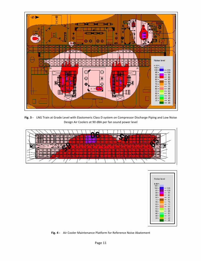
• Fig. 3 -‐ LNG Train at Grade Level with Elastomeric Class D system on Compressor Discharge Piping and Low Noise Design Air Coolers at 90 dBA per fan sound power level
• Fig. 4 -‐ Air Cooler Maintenance Platform for Reference Noise Abatement • Fig. 5 -‐ Air Cooler Maintenance Platform with change to Low Noise Design Air Coolers at 90 dBA per Fan
Sound Power Level • Fig. 6 -‐ Air Cooler Maintenance Platform with change to Elastomeric Class D System on Compressor
Discharge Piping only • Fig. 7 -‐ Air Cooler Maintenance Platform with change to Low Noise Design Air Coolers at 90 dBA per Fan
Sound Power Level and Elastomeric Class D System on Compressor Discharge Piping
Noise Abatement Effects at Grade Level
Fig. 1 shows the base case reference noise abatement levels at grade level within the LNG train. As the compressor piping is upgrade to the elastomeric foam Class D system (Fig. 2) we see a reduction in the area exceeding 85 dBA around the compressors of 16% and a further smaller 6% reduction on the area exceeding 85 dBA when the air coolers are changed to the 90 dBA per fan sound power level low noise design. While both of these options provide a reasonable reduction in the grade level noise the area exceeding 85 dBA is not totally eliminated and the areas near the compressors would still need to be designated as restricted areas.
This level of noise reduction for these noise abatement options would need to be carefully assessed during the FEED phase of the project. Based on in-‐plant noise levels these noise reduction measures may not be justified in the context of restricted areas, but, as will be discussed later, the impact on the community and compliance with community noise limits must also be considered.
Noise Abatement Effects at Air Cooler Maintenance Platform Level
The air cooler maintenance platform is an important work area within an LNG plant because maintenance activities may require personnel on the platform for extended periods. Many owners are keen to control the noise levels on this platform to manageable employee noise exposure levels.
The base case reference noise abatement with the 95 dBA per fan sound power levels (Fig. 4) has an extended area of the air cooler platform exceeding 85 dBA. When the air coolers are changed to the 90 dBA per fan sound power level (Fig. 5), we see a reduction in the areas exceeding 85 dBA of 7%. When only compressor discharge piping acoustic insulation is changed to the improved transmission loss elastomeric insulation (Fig.6), we see a similar 10% reduction in the area exceeding 85 dBA.
This demonstrates that on this elevated platform the influence of both air cooler noise and compressor piping noise, with enhanced noise abatement in both cases provide similar levels of noise reduction. When both the low noise design air coolers and enhanced elastomeric insulation are applied we see a more significant 37% reduction in the area exceeding 85 dBA, but the 85 dBA is not completely eliminated.
Again this information together with the design, layout and cost information, would need to be fully considered during FEED as part the decision making process on the air cooler noise limit and compressor piping insulation. This exercise would form the basis for ALARP analysis during FEED.
Noise Abatement Effects on Community Receptor
To evaluate the noise abatement effects on community noise we can consider a receptor located 1.0 Km away from the plant and assess performance against the US EPA Ldn – 55 dBA used by FERC, which translates to a Leq -‐ 48.6 dBA (24-‐hour equivalent continuous sound pressure level).

Page 8
Table 1 below shows the predicted noise levels at the community receptor for the range of noise abatement options available. The elastomeric insulation for the compressor discharge piping and the low noise 90 dBA per fan air coolers discussed earlier each only reduce the community receptor noise level by 1 dBA to 50 dBA. If both are applied to the design then the community noise level reduces to 49 dBA, still 1 dBA short of the target 48 dBA.
Other additional noise abatement options included going beyond the typical gas turbine suppliers standard 85 dBA at 1 m. acoustic enclosure package and applying custom fit acoustic blankets to the main compressor casings.
Table 1 – Community Noise Predictions for Residential Receptor 1.0 Km from Property Line
Reference Noise Abatement
Elastomeric Insulation on
Comp Discharge Piping
Low Noise Design Air Coolers
G/T Enclosures 80 dBA at 1m.
Acoustic Blankets on Compressors
Predicted Noise Level (dBA)
• 51 • 50 • 50 • • 49 • • • 48 • • • • 47
The predicted community noise levels show the importance and influence of compliance with these noise limits at residential receptors on the overall design of the plant. The base reference design starts at a predicted noise level of 51 dBA at the community receptor. To put some context on the required level of noise abatement to get the noise level at the receptor location down to 48 dBA is a 3 dBA reduction, which translates to reducing the overall acoustic energy being radiated by the plant (i.e. overall sound power level) by a factor of two.
Applying the already discussed noise abatement options for the compressor piping and air coolers, the two major groupings of noise sources in the LNG train, produces a reduction to 49 dBA, still short of the target 48 dBA. The additional step of reducing the gas turbine enclosures from 85 dBA at 1 m. to 80 dBA at 1m. and the gas turbine exhaust silencer from a sound power level 105 dBA to 100 dBA, just gets to the 48 dBA noise level at the receptor location. The additional measure of adding the acoustic blankets to the main compressor casing provides an additional 1 dBA of attenuation and brings the overall predicted noise level down to 47 dBA and provides some margin in the design.
It must be stressed that these noise abatement options must be applied in the correct order attacking the dominant noise sources first to reduce the overall noise levels. Applying the acoustic blankets to the compressors would not provide a 1 dBA reduction in the community noise level if the improved compressor piping acoustic insulation, low noise design air coolers and 80 dBA at 1 m. gas turbine package had not already be applied in the overall plant design.
Conclusions
The value of the KBR approach to LNG plant noise modeling, based on field validated noise survey data and verified by independent third-‐party noise surveys for world scale LNG facilities has been discussed in the context of a hypothetical LNG plant noise study. The importance of addressing noise control issues early in a project has been clearly demonstrated from the perspective of both in-‐plant noise levels and the important legislative requirements to control community noise levels to acceptable levels.
Community and in-‐plant noise levels are inextricably linked. Factors that influence in-‐plant noise also affects property line and community noise and vice versa. KBR’s modeling experience has demonstrated that a balanced approach to noise abatement with an understanding of the relative contributions of the major noise sources is

Page 9
essential. The major LNG plant noise sources are the air coolers and compressor piping followed by the gas turbine driven compressors. These are the sources where noise control effort needs to be focused during PreFEED/FEED and ALARP analysis with the plant owner.
This approach allows early definition of the noise abatement options in the context of layout and site location/configuration and other project drivers including cost and economic drivers. Then with plant owner input and consultation a reasonable and practical Noise Control Basis of Design for the EPC phase of the project can be developed during FEED to ensure that all noise abatement cost and design consideration are defined. The plant owner can only have confidence in this noise control basis of design if the engineering contractor can demonstrate that the noise modeling techniques have been validated and field verified.
References
1. James Cowling & Jon Richards “Centrifugal Compressor Piping Noise -‐ Field Measurements and Accurate Noise Modeling for Process Plants”, InterNoise 2012, 19-‐22 August 2012.
2. World Bank “Environmental, Health, and Safety General Guidelines” 30 April 2007. 3. ISO 15665:2003 Acoustics – “Acoustic insulation for pipes, valves and flanges” 4. Holland, K.R. and Fahy, F.J. “A Simple Transducer of Surface Vibrational Volume Velocity”, Institute of
Acoustics Proc. Vol. 15 Part 3. 5. Rainey, J.T. and Kushner, F. “Using a Soundtube to Measure Noise of Structural Sources in High
Background Noise Environments” Proceedings of the 9th Turbomachinery Symposium, Texas A&M University, 1980.
6. ISO 9613-‐1:1993 Acoustics – “Attenuation of sound during propagation outdoors -‐-‐ Part 1: Calculation of the absorption of sound by the atmosphere”.
7. ISO 9613-‐2:1996 Acoustics – “Attenuation of sound during propagation outdoors -‐-‐ Part 2: General method of calculation”.

Page 10
Fig. 1 -‐ Predicted LNG train noise contours at grade level for an LNG train with 2 X LMS 100 gas turbine drives for the main compressors (2 in 1 configuration)
Fig. 2 -‐ LNG Train at Grade Level with Elastomeric Class D System on Compressor Discharge Piping
Page 11
Fig. 3 -‐ LNG Train at Grade Level with Elastomeric Class D system on Compressor Discharge Piping and Low Noise Design Air Coolers at 90 dBA per fan sound power level
Fig. 4 -‐ Air Cooler Maintenance Platform for Reference Noise Abatement

Page 12
Fig. 5 -‐ Air Cooler Maintenance Platform with change to Low Noise Design Air Coolers at 90 dBA per Fan Sound Power Level
Fig. 6 -‐ Air Cooler Maintenance Platform with change to Elastomeric Class D System on Compressor Discharge Piping only

Page 13
Fig. 7 -‐ Air Cooler Maintenance Platform with change to Low Noise Design Air Coolers at 90 dBA per Fan Sound Power Level and Elastomeric Class D System on Compressor Discharge Piping