cancer cell detection and invasion depth estimation in brightfield … · cells from the tissue of...
TRANSCRIPT
P. QUELHAS et al.: CANCER CELL DETECTION AND INVASION DEPTH ESTIMATION 1
Cancer cell detection and invasion depthestimation in brightfield images
Pedro Quelhas1
Monica Marcuzzo1
Ana Maria Mendonça12
Maria José Oliveira1
Aurélio Campilho12
1 INEB - Instituto de EngenhariaBiomédica, Porto, Portugal
2 Universidade do Porto, Faculdade deEngenharia, Departamento de Engen-haria Electrotécnica e Computadores
Abstract
The study of cancer cell invasion under the effect of different conditions is funda-mental for the understanding of the invasion mechanism and to test possible therapiesfor its regulation. In this study, to simulate cancer cell invasion across tissue basementmembrane, biologists established in vitro invasion assays with cancer cells invading ex-tracellular matrix components. However, analysis of the assay is manual, being time-consuming and error-prone, which motivates an objective and automated analysis tool.
With the objective of automating the analysis of cell invasion assays we present anew methodology to detect cells in 3D matrix cell assays and correctly estimate theirinvasion, measured by the depth of the penetration in the gel. Detection is based on thesliding band filter, by evaluating the gradient convergence and not intensity. As such itcan detect low contrast cells which otherwise would be lost. For cell depth estimationwe present a new tool based on the analysis of cell detections from multiple brightfieldimages taken at different depths of focus, using a new focus estimation approach basedon the convergence gradient’s magnitude. The final cell detection’s precision and recallare of 0.896 and 0.910 respectively, and the average error in the cell’s position estimateis of 0.41µm, 0.37µm and 3.7µm in the x, y and z directions, respectively.
1 IntroductionInvasion, an important step in the development of cancer, consists on the extravasation ofcells from the tissue of origin into neighbor tissues. While invading, cancer cells establisha continuous molecular crosstalk with host elements of the surrounding microenvironment.In the case of gastric microenvironment, such elements consist of extracellular matrix com-ponents, bacteria and host cells, such as fibroblasts, myofibroblasts, endothelial cells, andmacrophages. The absence of good models to study the interactions between invasive can-cer cells and the other elements of the tumor microenvironment, led to the construction of
c© 2009. The copyright of this document resides with its authors.It may be distributed unchanged freely in print or electronic forms.
BMVC 2009 doi:10.5244/C.23.68
2 P. QUELHAS et al.: CANCER CELL DETECTION AND INVASION DEPTH ESTIMATION
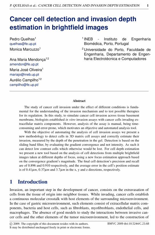
Figure 1: Scheme of the cell invasion assay: a dish well is made to contain a certain amountof gel upon which cells are deposited (red surface cells). With the passing of time cancercells invade the gel matrix (blue invading cells).
innovative 3D invasion assay [2]. However, the task of evaluating the results of such assaysis performed manually by microscopic observation, which is time-consuming, fatiguing, andprone to human errors, requiring frequent repetitions towards validation [2]. These limita-tions constitute a clear motivation for integrating automation in the analysis of such assays.
Most 3D analysis of cells is based on confocal microscopy which has the capacity toimage a single focal plane with little or no interference from out of focus objects [1, 4].However, researchers use brightfield microscopy which is much simpler and allow for theobservation of cells at different depths, which increases the difficulty of cell detection andcell depth estimation. Cell depth is in this case characterized by the best focal plane and isbased on the variation of depth of focus.
We present a tool to evaluate 3D cell invasion based on the analysis of multiple brightfieldimages taken at different depths of focus, using a new estimation approach. Cell depth is inthis case characterized by the best focal plane and is based on the variation of depth of focustowards the surface focus.
Automated cell analysis in microscopic images has been explored by many applications.However, most automated cell analysis approaches are based on segmentation [3, 7]. Whileoften used, segmentation for cell detection is semi-automated at best and requires frequentparameter readjustments due to image variability. The most prominent problem with seg-mentation is its inability to deal with cell clusters, which are detected as one entity. Toobtain a successful detection even at low contrast we investigate the use of a particular con-vergence filter, the Sliding Band Filter (SBF) [8], for cell detection in brightfield microscopyimages. SBF is based on image gradient convergence and not intensity. As such, it can detectlow contrast cells which otherwise would be lost in the background noise.
The main problem in the analysis of cancer cell invasion assays is that due to the bright-field imaging and the cell’s transparency, cells appear at several focal planes giving rise tomultiple detections. To solve the multiple detection problem we propose the use of 3D lo-cation information by stacking multiple detections and filtering out false detections. Fromthese 3D stacks of cell detection we present a focus measure to estimate the degree of focusof each detection, determining in this way the location of each cell in 3D. This is the finaldesired result and provides all necessary information to analyse the invasion assay.
This paper is organized as follows: Section 2 describes the biology experiments and data,Section 3 describes our cell detection approach and our cell depth estimation approach. Insection 4 we present the results. Finally, conclusion is presented in Section 5.
2 Biological Experimental Setup and Data CollectionIn their general formulation cancer cell invasion assays consist of gels of extracellular ma-trix components (collagen type I or Matrigel, for instance), on top of which isolated cancer
P. QUELHAS et al.: CANCER CELL DETECTION AND INVASION DEPTH ESTIMATION 3
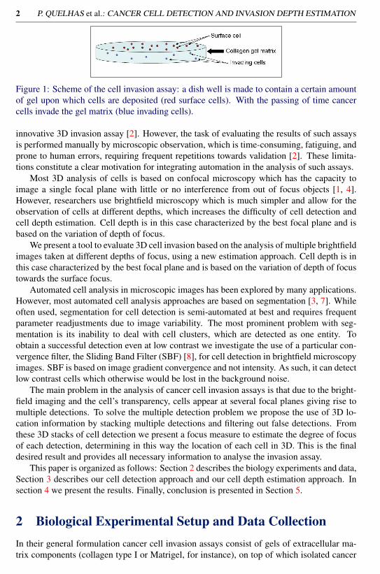
Figure 2: Images from the 3D focus stack from a cancer cell invasion assay (croped to fitfigure). Images obtained focused on the surface of the gel where most cells are, at −20µmwhere some invading cells can already be seen, at −40µm and −60µm where only invasivecells can be seen in focus.
cells, treated or not with specific drugs, are added (Figure 1).Alternatively, the extracellularmatrix might be intermixed or not with other host cells (such as fibroblasts, endothelial cellsor macrophages. After 24 hours of incubation at 37◦ C and 5% CO2 atmosphere, the sys-tem is visualized using an inverted Zeiss microscope.The experiments used to validate ourmethodology were prepared by adding naturally invasive or non-invasive cancer cells, in theabsence of any additional treatment, to the top of collagen type I gels without cancer cellsintermixed. In the case of the experiments used to validate our methodology collagen gelwas used and no macrophages or fibroblasts were introduced into the culture.
To obtain the image data which will enable us to estimate cell invasion, a stack of imagesis collected varying the depth of focus. The images are collected from a depth above thesurface until past the depth of the most invasive of all cells within the field of view, withfocus being varied in 5µm steps. The joint focal length and camera CCD resolution give aspatial scale of 0.256µm per pixel, each image size being 1388×1040 pixels. Examples ofthe collected images can be seen in Figure 2.
2.1 In focus definition
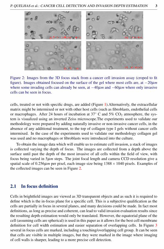
Cells in brightfield images are viewed as 3D transparent objects and as such it is required todefine which is the in-focus plane for a specific cell. This is a subjective qualification as thecells are partially in focus in several planes, and many decisions could be made. In fact mostdefinitions, as long as precise and coherent, can lead to valid invasion evaluation results sincethe resulting depth estimation would only be translated. However, the equatorial plane of thecell (assuming cells are spherical) is used in this paper as it allows for the best cell membranedefinition for cell width estimation and easier separation of overlapping cells. In Figure 3several in focus cells are marked, including a touching/overlapping cell group. It can be seenthat cells are visible in multiple images, but they were marked in the image where imagingof cell walls is sharper, leading to a more precise cell detection.
4 P. QUELHAS et al.: CANCER CELL DETECTION AND INVASION DEPTH ESTIMATION
Figure 3: Detail of focus images through varying focus lengths (from −60µm (top left) to+25µm (bottom right) relative to the surface; in-focus cells are marked at the respectivefocal plane where the cell membrane is sharper.
3 MethodologyTo evaluate the cancer cell invasion in 3D collagen matrix assays we need first to detectall possible cells at all focus depths, then decide which detections correspond to valid celllocations and finally evaluate the most likely depth for each detected cell. As such ourmethodology can be divided into three steps:
• Cell detection in each image. As each image contains in focus and out of focus cells,the amount of detected cells be larger than the total number of cells in the 3D volume.
• After 2D detection we search for cell detection, at adjacent planes, which are closeto each other, associating them in a stack, each representing a possible cell at a deter-mined (x,y) location. However, the z or depth for each cell is still unknown.
• Finally, for each detection stack, estimation of the most likely image plane for thecell’s location. This enables the determination the 3D position for each cell.
The following sections give details on each of the steps in our methodology.
3.1 2D Cell DetectionFor the task of cell detection we base our decision on image enhancement through filtering,where locations which correspond to cell will have strong filter response. Subsequently, cellsare associated with the locations of filter maxima response.
Most cell detection approaches are based on image segmentation. These approachesassume that cells are mostly isolated with few agglomerated cases that must be solved [3, 7].However, in our case, cell’s appear often in groups and, as they are in a 3D structure, canappear superimposed and with different intensities (different focus level). The difficultyof segmentation also increases due to the fact that the images in this case are obtained bybrightfield microscopy.
Our approach to cell detection is based on finding the approximated round shape char-acteristic of cells. To perform such detection we use a convergence index filter [5]. Con-

P. QUELHAS et al.: CANCER CELL DETECTION AND INVASION DEPTH ESTIMATION 5
(a) (b) (c) (d)
Figure 4: SBF filter schematics (a), and examples of cell detection using the SBF filter: (b)brightfield image containing in-focus, out-of-focus and grouped cells, (c) filter response forimage (b), (d) final detection of cells in the image.
vergence Index (CI) filters are based on the maximization of the convergence index at eachimage point of spatial coordinates (x,y), defined by:
C(x,y) =1M ∑
(k,l)∈Rcosθ(k, l), (1)
where M is the number of points in the filter support region R, θ is the angle between thegradient vector calculated for point (k, l) and the direction of the line that connects points(x,y) and (k, l).
The main difference between distinct CI filters is the definition of the support region R,which is formed by radial lines that emerge from the point where the filter response is beingcalculated, as shown in Figure 4(a). There are several CI filters: coin filter (CF) [5], irisfilter (IF) [5], adaptive ring filter (ARF) [5, 10] and the recently proposed sliding band filter(SBF) [8]. The CF uses a circle with variable radius as support region, the IF maximizesthe convergence index by adapting the radius value on each direction and the ARF uses aring shaped region with fixed width and varying radius. Finally, the SBF combines the basicideas of IF and ARF by defining a support region formed by a band of fixed width, whoseposition is changed in each direction to allow the maximization of the convergence index ateach point. The set of band positions that maximizes the convergence index at each pointwill be called as band support points. The more generic formulation of the SBF gives a widerdetection range of shapes in comparison with other convergence filters. This is desirable forour application due to possible variations in the shapes that the cells can exhibit. SBF isdefined by:
SBF(x,y) =1N
N
∑i=1
(max
Rmin≤n≤Rmax
(1d
n+d/2
∑m=n−d/2
cos(θ(i,m))
)), (2)
where N is the number of support region lines that irradiate from (x,y), d is the band width,n is the position of the band in a line that varies from Rmin to Rmax, and θ(i,m) is the anglebetween the image gradient vector direction at location m and the direction that is currentlybeing analyzed i (see Figure 4(a) for filter design schematics).
However, the SBF detects only convergence or divergence. In the case of cell imagein brightfield microscope the cytoplasm is not visible, only the cell membrane is visible.This membrane is a location of both convergence and divergence. By ignoring the sign ofthe convergence factor cos(θ(i,m)) in the SBF filter we can modify the filter to best fit the

6 P. QUELHAS et al.: CANCER CELL DETECTION AND INVASION DEPTH ESTIMATION
(a) (b) (c)
Figure 5: Examples for MSBF cell detections (a) and (b). Detail of cell detection in theoccurrence of severe overlap of cells (c). Red points represent the band support points (pointof stronger convergence). The cell membrane is considered the line connecting all bandsupport points (green line).
location we aim at detecting. The Modified Sliding Band Filter (MSBF) is given by:
MSBF(x,y) =1N
N
∑i=1
(max
Rmin≤n≤Rmax
(1d
n+d/2
∑m=n−d/2
‖cos(θ(i,m))‖
)), (3)
After the application of the MSBF filter, cells are associated with the locations of filtermaxima response. The maxima are obtained by non-maxima suppression filtering and aminimum distance of Rmin between maxima is enforced.
After locating the cell’s center coordinates, we must estimate their shapes and sizes inorder to complete their detection. To do so we investigate, for each filter maximum, whatwere the positions of the sliding band that contributed to that particular maximum. These arethe band support points SP = {(xSP(i),ySP(i)), i = 1 . . .N} and are defined as:
xSP(i) = x+nmax(i)cos( 2π
N (i−1))
ySP(i) = y+nmax(i)sin( 2π
N (i−1))
nmax(i) = argmaxRmin<n<Rmax
(1d ∑
n+d/2m=n−d/2 cos(θ(i,m))
) (4)
where N is the number of support region lines and nmax(i) corresponds to the radius of thesupport point for support region line i.
In fact, the position of the band that maximizes the convergence index response in eachdirection of the MSBF region of support gives an indication of the cells’ border locationin that specific direction (Figure 4(d) and 5). The final border for the cell detection is theline connecting the band support points. The final detection result gives the 2D locations ofcells in each image. The cell detection result can include in-focus cells, detections of theout-of-focus image of cells from adjacent planes or noise triggered detections.
3.2 Cell Detection StackingGiven all the cells detected in each individual 2D image plane of the 3D stack of imageswe must now relate each cell in a 2D plane with all possible corresponding cells. This isperformed based on a 2D distance between cells in adjacent planes, with the requirementof reciprocity. For each cell detection d in image I, with coordinates (x(I,d),y(I,d)), the 2Ddistance to all other cell detections in the adjacent plane is obtained and the closest detectiond′ for image I +1 at location (x(I+1,d′),y(I+1,d′)) is considered to correspond to the same cell.

P. QUELHAS et al.: CANCER CELL DETECTION AND INVASION DEPTH ESTIMATION 7
Figure 6: Detections after stacking: blue dotted contours are detected cells which did notget stacked due to non-conformity with stacking requirements. Also visible are some cellswhich were not detected and have no contour.
Cell detection correspondence is only valid if the 2D distance between d and d′ is lower thana threshold and if the closest detection criteria is reciprocal (d must be the closest detectionto d′ for all possibilities in image I). The final 3D stack is composed of the detection indexesd for each image plane in the stack, or zero in the case where the stack has no detections.
Additionally we also impose continuity of stacks (splitting stacks if there is no corre-spondence) and impose a minimum number of detections for a stack of cells to be valid.Using these constraints reduces the probability that erroneous detections may be stacked asit is unlikely for noise to be spatially consistent in z. More details on the specific values usedfor this implementation are presented in the result section.
3.3 Depth EstimationOne of the MSBF filter main properties is that its result is not depending on the magnitude ofthe image’s gradient. This is particularly useful for the specific application of cell detection,allowing the detection even when image contrast is reduced. Moreover, we propose to usethis gradient magnitude information to estimate cell depth for the detected cells.
We propose a focus estimator based on the magnitude of the convergence at the bandsupport points. It is a know property from depth from focus methods that an object is morefocused if its borders are sharper [6, 9]. As such we define the focus estimation measure as:
FE(x,y) =1N
N
∑i=1
(1d
nmax(i)+d/2
∑m=nmax(i)−d/2
mag(grad(i,m))∗‖cos(θ(i,m))‖
), (5)
where mag(grad(i,m)) is the gradient magnitude of the image at location m in the i filter’ssupport line and nmax(i) is the support point for support region line i.
For a given (x,y) coordinate we can now obtain a focus estimation which has a highervalue if those coordinates correspond to an in-focus cell than if they correspond to an out-of-focus cell. In Figure 7 we can observe the value (rounded) of the focus estimator for a cellover several images taken at different focal depths. The progression of the focus estimationvalue is intuitive and in accordance with the definition of in-focus cell proposed in section 2.
Focus estimator value is also used to validate the cell detection stacks. If a detectionstack does not have a minimum value of focus for any cell detection it is assumed that thestack contains detection of a cell that is never in focus (or noise), as such it is removed.
4 Results and DiscussionTo evaluate the proposed methodology we use a dataset of 4 independent invasion assayswhere a total of 84 image planes where collected, every 5µm in depth. The total sum of cells

8 P. QUELHAS et al.: CANCER CELL DETECTION AND INVASION DEPTH ESTIMATION
Figure 7: Focus estimator value for a given cell for several focus planes.
in the dataset is of 320. To set the parameters for out methodology an auxiliary (independent)dataset was used with 25 images, containing 70 cells, from an additional invasion assay.
The dataset was annotated, by a researcher under supervision of the project’s leadingbiologist, by selecting the best (x,y,z) coordinate for each cell. This annotation was usedto evaluate the presented methodology’s performance. The protocol used was based the ondistance between annotation and detection, imposing a threshold of 10 pixels and a recip-rocal minimal distance between annotation and detection. Cell that obey this criteria areconsidered to be correctly detected.
4.1 Parameter SettingsUsing the auxiliary dataset we set the parameters for cell detection and detection stacking sothat results were at the equal error rate between false and miss detections.
For the MSBF filter parameters we chose: Rmin = 5, Rmax = 20, q = 5, N = 32. Thesewere selected both by visual inspection of the results and by setting the parameters close tothose known from the data (empirically some parameters are related to the intrinsic propertiesof the cells in the images, cell size gives indication of the adequate values for Rmin, Rmax andq). However, it was found that cell detection using the MSBF is robust to parameters, withmany different parameter setting producing visually similar results. For detection stacking(second step in the methodology) we chose a distance threshold of 10 pixels.
The depth estimation step has no new parameters and uses those set for the MSBF filter.However, for an increase in robustness we impose a minimum of 5 for the focus measure forany final cell detection. This setting was set for the equal error rate in the validation set.
4.2 Cell DetectionWe applied the MSBF filter to all images in the test dataset and obtained all detection for eachplane, we then stacked and searched for the best candidate for the in-focus plane. Finally,we evaluated the correspondences to the annotation as described before. Table 1 shows thecell detection results. The average precision and recall for the presented methodology is of0.896 and 0.910 respectively and the average number of false positives and false negativesare of 8.75 and 7.5 respectively. No evaluation of the correctness of detected cells’ shapewas performed since the annotation does not contain ground truth for the cells’ shape Thesenumbers do not change greatly with the distance threshold as the reciprocal requirement forcorrespondences is stricter than the distance threshold. It was found that the most influentialparameter for error regulation is the minimum focus estimate threshold in stack validation.
4.3 Depth EstimationIn addition to evaluate the cell detection in the 3D cell matrix we need to evaluate what arethe errors in the positioning in the final cell’s coordinates. It is not enough to ensure that
P. QUELHAS et al.: CANCER CELL DETECTION AND INVASION DEPTH ESTIMATION 9
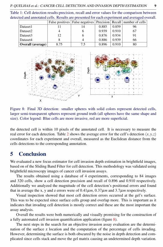
Table 1: Cell detection results:precision, recall and error values for the comparison betweendetected and annotated cells. Results are presented for each experiment and averaged overall.
False positives False negatives Precision Recall number of cellsDataset1 11 14 0.885 0.859 96Dataset2 4 6 0.939 0.910 67Dataset3 12 6 0.876 0.934 91Dataset4 8 4 0.886 0.939 66Overall (average) 8.75 7.5 0.896 0.910 80
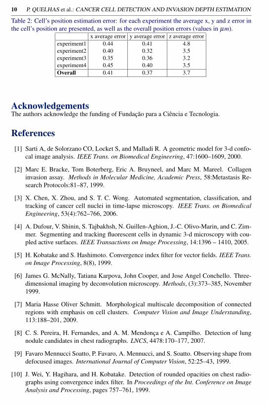
Figure 8: Final 3D detection: smaller spheres with solid colors represent detected cells,larger semi-transparent spheres represent ground truth (all spheres have the same shape andsize). Color legend: Blue cells are more invasive, red are more superficial.
the detected cell is within 10 pixels of the annotated cell. It is necessary to measure thereal error for each detection. Table 2 shows the average error for the cell’s detection (x,y,z)coordinates for each experiment and overall, measured as the Euclidean distance from thecells detections to the corresponding annotation.
5 ConclusionWe evaluated a new focus estimator for cell invasion depth estimation in brightfield images,based on of the Sliding Band Filter for cell detection. This methodology was validated usingbrightfield microscopy images of cancer cell invasion assays.
The results obtained using a database of 4 experiments, corresponding to 84 imagesand 320 cells, show a cell detection precision and recall of 0.896 and 0.910 respectively.Additionally we analyzed the magnitude of the cell detection’s positional errors and foundthat in average the x, y and z errors were of 0.41µm, 0.37µm and 3.7µm respectively.
Visual inspection showed that most cell detection errors occurred at the gel’s surface.This was to be expected since surface cells group and overlap more. This is important as itindicates that invading cell detection is mostly correct and these are the most important theassay analysis.
Overall the results were both numerically and visually promising for the construction ofa fully automated cell invasion quantification application (figure 8).
The next steps in the search for an objective invasion assay evaluation are the determi-nation of the surface z location and the computation of the percentage of cells invading.However, determining the surface is both obscured by the noise in depth detection and com-plicated since cells stack and move the gel matrix causing an undetermined depth variation.
10 P. QUELHAS et al.: CANCER CELL DETECTION AND INVASION DEPTH ESTIMATION
Table 2: Cell’s position estimation error: for each experiment the average x, y and z error inthe cell’s position are presented, as well as the overall position errors (values in µm).
x average error y average error z average errorexperiment1 0.44 0.41 4.8experiment2 0.40 0.32 3.5experiment3 0.35 0.36 3.2experiment4 0.45 0.40 3.5Overall 0.41 0.37 3.7
AcknowledgementsThe authors acknowledge the funding of Fundação para a Ciência e Tecnologia.
References[1] Sarti A, de Solorzano CO, Locket S, and Malladi R. A geometric model for 3-d confo-
cal image analysis. IEEE Trans. on Biomedical Engineering, 47:1600–1609, 2000.
[2] Marc E. Bracke, Tom Boterberg, Eric A. Bruyneel, and Marc M. Mareel. Collageninvasion assay. Methods in Molecular Medicine, Academic Press, 58:Metastasis Re-search Protocols:81–87, 1999.
[3] X. Chen, X. Zhou, and S. T. C. Wong. Automated segmentation, classification, andtracking of cancer cell nuclei in time-lapse microscopy. IEEE Trans. on BiomedicalEngineering, 53(4):762–766, 2006.
[4] A. Dufour, V. Shinin, S. Tajbakhsh, N. Guillen-Aghion, J.-C. Olivo-Marin, and C. Zim-mer. Segmenting and tracking fluorescent cells in dynamic 3-d microscopy with cou-pled active surfaces. IEEE Transactions on Image Processing, 14:1396 – 1410, 2005.
[5] H. Kobatake and S. Hashimoto. Convergence index filter for vector fields. IEEE Trans.on Image Processing, 8(8), 1999.
[6] James G. McNally, Tatiana Karpova, John Cooper, and Jose Angel Conchello. Three-dimensional imaging by deconvolution microscopy. Methods, (3):373–385, November1999.
[7] Maria Hasse Oliver Schmitt. Morphological multiscale decomposition of connectedregions with emphasis on cell clusters. Computer Vision and Image Understanding,113:188–201, 2009.
[8] C. S. Pereira, H. Fernandes, and A. M. Mendonça e A. Campilho. Detection of lungnodule candidates in chest radiographs. LNCS, 4478:170–177, 2007.
[9] Favaro Mennucci Soatto, P. Favaro, A. Mennucci, and S. Soatto. Observing shape fromdefocused images. International Journal of Computer Vision, 52:25–43, 1999.
[10] J. Wei, Y. Hagihara, and H. Kobatake. Detection of rounded opacities on chest radio-graphs using convergence index filter. In Proceedings of the Int. Conference on ImageAnalysis and Processing, pages 757–761, 1999.