capancdt 6300/6310 - micro-epsilon messtechnik gmbh & co. kg königbacher strasse 15 94496...
TRANSCRIPT

CS005CS02CSH02CSH02FLCS05 CSE05 CSH05
CSH05FLCS08 CS1CSE1 CSH1CSH1FLCS1HP
CSH1.2 CSH1.2FLCSH2FL CS2CSH2CSE2 CS3
CS5CS10CSG0.50 CSG1.00
Operating Instructions
capaNCDT 6300/6310

MICRO-EPSILON MESSTECHNIKGmbH & Co. KGKönigbacher Strasse 15
94496 Ortenburg / Germany
Tel. 08542/168-0Fax 08542/168-90e-mail [email protected]
Non-contact Capacitive Displacement Measuring
capaNCDT 6300 / 6310
Contents
1. Safety .......................................................................................................................................... 51.1 Symbols Used .................................................................................................................................................... 51.2 Warnings ............................................................................................................................................................ 51.3 Notes on CE Marking ......................................................................................................................................... 61.4 Intended Use ...................................................................................................................................................... 61.5 Proper Environment ........................................................................................................................................... 7
2. Functional Principle, Technical Data ......................................................................................... 82.1 Measuring Principle ........................................................................................................................................... 82.2 Structure ............................................................................................................................................................. 92.2.1 Sensors ............................................................................................................................................................ 102.2.2 Sensor Cable ................................................................................................................................................... 122.2.3 Preamplifier (DT6310 only) .............................................................................................................................. 132.2.4 Preamplifier Cable (DT6310 only) .................................................................................................................... 132.2.5 Controller .......................................................................................................................................................... 142.3 Technical Data .................................................................................................................................................. 15
3. Delivery .................................................................................................................................... 163.1 Unpacking ....................................................................................................................................................... 163.2 Storage ............................................................................................................................................................. 16
4. Installation and Assembly ........................................................................................................ 174.1 Precautionary Measures .................................................................................................................................. 174.2 Sensor .............................................................................................................................................................. 174.2.1 Radial Point Clamping with Grub Screw, Cylindric Sensors ........................................................................... 174.2.2 Circumferential Clamping, Cylindric Sensors.................................................................................................. 184.2.3 Flat Sensors ..................................................................................................................................................... 184.2.4 Dimensional Drawings Sensors ....................................................................................................................... 194.3 Sensor Cable ................................................................................................................................................... 254.4 Preamplifier CP6001 ........................................................................................................................................ 264.5 Preamplifier Cable ........................................................................................................................................... 284.6 Controller .......................................................................................................................................................... 294.7 Ground Connection, Earthing .......................................................................................................................... 304.8 Power Supply, the Display/Output Device and Synchronization .................................................................... 304.9 Pin Assignment ................................................................................................................................................ 32
capaNCDT 6300 / 6310
5. Operation .................................................................................................................................. 355.1 Starting Up ....................................................................................................................................................... 355.2 Basic Settings .................................................................................................................................................. 355.3 Calibration with Metal Targets .......................................................................................................................... 375.4 Linearity Adjustment and Calibration with Insulator Targets ........................................................................... 385.5 Changing Limit Frequency............................................................................................................................... 40
6. Measurement ............................................................................................................................ 41
7. Operation and Maintenance .................................................................................................... 41
8. Liability for Material Defects .................................................................................................... 42
9. Decommissioning, Disposal .................................................................................................... 42
10. Accessories, Service ................................................................................................................ 43
Page 5
Safety
capaNCDT 6300 / 6310
1. Safety
System operation assumes knowledge of the operating instructions.
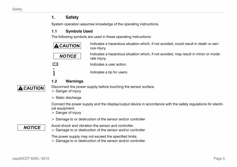
1.1 Symbols UsedThe following symbols are used in these operating instructions:
Indicates a hazardous situation which, if not avoided, could result in death or seri-ous injury.
Indicates a hazardous situation which, if not avoided, may result in minor or mode-rate injury.
Indicates a user action.
i Indicates a tip for users.
1.2 WarningsDisconnect the power supply before touching the sensor surface.
> Danger of injury
> Static discharge
Connect the power supply and the display/output device in accordance with the safety regulations for electri-cal equipment.
> Danger of injury
> Damage to or destruction of the sensor and/or controller
Avoid shock and vibration the sensor and controller. > Damage to or destruction of the sensor and/or controller
The power supply may not exceed the specified limits. > Damage to or destruction of the sensor and/or controller

Page 6
Safety
capaNCDT 6300 / 6310
Protect the sensor cable against damage > Destruction of the sensor
> Failure of the measuring device
1.3 Notes on CE Marking
The following apply to the capaNCDT 6300/6310: - EU Directive 2014/30/EU - EU Directive 2011/65/EU
Products which carry the CE mark satisfy the requirements of the EU directives cited and the Europeanharmonized standards (EN) listed therein. The EU Declaration of Conformity is available to the responsibleauthorities according to EU Directive, article 10, at:
MICRO-EPSILON Messtechnik GmbH & Co. KGKönigbacher Straße 15 94496 Ortenburg / Germany
The measuring system is designed for use in industrial environments and meets the requirements.
1.4 Intended Use - The capaNCDT 6300/6310 measuring system is designed for use in industrial applications. It is used for
� displacement, distance, thickness and movement measurement � position measuring of parts or machine components
- The system may only be operated within the limits specified in the technical data, see Chap. 2.3. - The system must only be used in such a way that no persons are endangered or machines and other
material goods are damaged in the event of malfunction or total failure of the controller. - Take additional precautions for safety and damage prevention in case of safety-related applications.
Page 7
Safety
capaNCDT 6300 / 6310
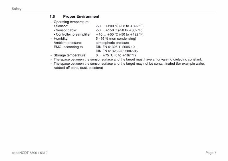
1.5 Proper Environment - Operating temperature:
�Sensor: -50 ... +200 °C (-58 to +392 °F) �Sensor cable: -50 ... +150 C (-58 to +302 °F) �Controller, preamplifier: +10 ... +50 °C (-50 to +122 °F)
- Humidity: 5 - 95 % (non condensing) - Ambient pressure: atmospheric pressure - EMC: according to DIN EN 61326-1: 2006-10
DIN EN 61326-2-3: 2007-05 - Storage temperature: 0 ... +75 °C (0 to +167 °F) - The space between the sensor surface and the target must have an unvarying dielectric constant. - The space between the sensor surface and the target may not be contaminated (for example water,
rubbed-off parts, dust, et cetera)

Page 8
Functional Principle, Technical Data
capaNCDT 6300 / 6310
2. Functional Principle, Technical Data
2.1 Measuring Principle
The principle of capacitive distance measurement with the capaNCDT system is based on the principle of the parallel plate capacitor. For conductive targets, the sensor and the target opposite form the two plate elec-trodes.
If a constant AC current flows through the sensor capacitor, the amplitude of the AC voltage at the sensor is proportional to the distance between the capacitor electrodes. The AC voltage is demodulated, amplified and output as an analog signal.
The capaNCDT system evaluates the reactance XC of the plate capacitor which changes strictly in proportion to the distance.
X = ; capacitance C = * * c1
jC area
distancer o
i A small target and bent (uneven) surfaces cause a non-linear characteristic.
This theoretical relationship is realized almost ideally in practice by designing the sensors as guard ring capaci-tors.
The linear characteristic of the measuring signal is achieved for electrically conductive target materials (metals) without any additional electronic linearization. Slight changes in the conductivity or magnetic proper-ties do not affect the sensitivity or linearity.
The capaNCDT system also measures reliably against insulating materials. The linear behavior for this catego-ry of targets is achieved by special electronic circuitry. A constant relative dielectric of the material is, however, a prerequisite for accurate measurement.
Electrical conductor
Ground
Screening electrode
Measuring electrode
Fig. 1 Functional principle of the guard ring capacitor

Page 9
Functional Principle, Technical Data
capaNCDT 6300 / 6310
2.2 Structure
The non-contact, single-channel measuring system installed in an aluminum housing, consists of: - Sensor, - Sensor cable - Preamplifier (DT6310 only) - Preamplifier cable (DT6319 only) - Controller
Two versions with different kind of preamplifier are available: - DT6300: Controller with integrated preamplifier, distance sensor and controller: 1 m - DT6310: Controller with external preamplifier, distance sensor and controller: up to 20 m
Controller: DT6300
Oscillator
Demo-dulator
Power supplyIn-/Outputs
Sensorcable Sensor
Power supply PS300/15
Pre-amplifier
Controller: DT6310
Oscillator
Demo-dulator
Power supplyIN-/Outputs
Sensorcable Sensor
Power supply PS300/15
Pre-amplifier
Preamplifier-cable
Fig. 2 Block diagram capaNCDT 6300 Fig. 3 Block diagram capaNCDT 6310

Page 10
Functional Principle, Technical Data
capaNCDT 6300 / 6310
2.2.1 Sensors
For this measurement system, several sensors can be used. In order to obtain accurate measuring results, keep the surface of the sensor clean and free from dam-
age.
The capacitive measuring process is area-related. A minimum area (see table) is required depending on the sensor model and measuring range. In the case of insulators the dielectric constant and the target thickness also play an important role.
Sensors for electrical conducting targets (metals)
Sensor model Measuring range Min. target diameterCS005 0.05 mm 3 mmCS02 0.2 mm 5 mm
CSH02 0.2 mm 7 mmCSH02FL 0.2 mm 7 mm
CS05 0.5 mm 7 mmCSE05 0.5 mm 6 mmCSH05 0.5 mm 7 mm
CSH05FL 0.5 mm 7 mmCS08 0.8 mm 9 mmCS1 1 mm 9 mm
CSE1 1 mm 8 mmCSH1 1 mm 11 mm
CSH1FL 1 mm 11 mmCS1HP 1 mm 9 mmCSH1.2 1.2 mm 11 mm
CSH1.2FL 1.2 mm 11 mmCSH2FL 2 mm 17 mm
CS2 2 mm 17 mmCSH2 2 mm 17 mmCSE2 2 mm 14 mmCS3 3 mm 27 mm

Page 11
Functional Principle, Technical Data
capaNCDT 6300 / 6310
CS5 5 mm 37 mmCS10 10 mm 57 mm
CSG0.50 0.5 mm ca. 7 x 8 mmCSG1.00 1.00 mm ca. 8 x 9 mm
Sensors for insulating targets materials.
The sensors also measure reliable against insulating materials. The linear behavior for this category of targets is achieved by special linearization, see Chap. 5.4. The measuring ranges of the respective sensors depend on the er of the target.

Page 12
Functional Principle, Technical Data
capaNCDT 6300 / 6310
2.2.2 Sensor Cable
The sensor and controller respectively sensor and preamplifier are connected by a special, double screened, 1 m (3 ft) long sensor cable.
Do not shorten or lengthen these special cables.
Usually, a damaged cable can not be repaired.
i Switch off the device when plugging and removing connectors. Do not crush the sensor cable. Do not modify to the sensor cable.
The sensors of type CSH have integrated a 1.4 long sensor cable. Cable lengths of 2.8 m are available too if required.
Model Cable length 2 axial connector 1x axial + 1x 90 ° For sensors Minimum bending ra-dius: 10 mm (once) 38 mm (permanently)
CC1C 1 m x 0.05 - 0.8 mmCC2C 2 m x 0.05 - 0.8 mmCC3C 3 m x 0.05 - 0.8 mmCC4C 4 m x 0.05 - 0.8 mmCC1C/90 1 m x 0.05 - 0.8 mmCC2C/90 2 m x 0.05 - 0.8 mmCC3C/90 3 m x 0.05 - 0.8 mmCC4C/90 4 m x 0.05 - 0.8 mmCC1B 1 m x 1 ... 10 mmCC2B 2 m x 1 ... 10 mmCC3B 3 m x 1 ... 10 mmCC4B 4 m x 1 ... 10 mmCC1B/90 1 m x 1 ... 10 mmCC2B/90 2 m x 1 ... 10 mmCC3B/90 3 m x 1 ... 10 mmCC4B/90 4 m x 1 ... 10 mm

Page 13
Functional Principle, Technical Data
capaNCDT 6300 / 6310
2.2.3 Preamplifier (DT6310 only)
The preamplifier is necessary as connector between sensor and controller. With this preamplifier it is possible to deal with greater distances between sensor and controller. The sensor cable length is fixed at 1 m (4 m with additional adjustment of the controller) and must not be modified by the user.
Fig. 4 Preamplifier CP6001
2.2.4 Preamplifier Cable (DT6310 only)
The cable carriers capable preamplifier cable connect the preamplifier with the controller. It is possible to handle a distance of up to 20 m.
The user may not shorten or lengthen these special cables. Usually, a damaged cable can not be repaired.
Model Cable length Min. bending radius, permanentCA5 5 m
33 mmCA10 10 mCA20 20 mCA25 25 m

Page 14
Functional Principle, Technical Data
capaNCDT 6300 / 6310
2.2.5 Controller
The controller principally consists of an oscillator- and a demodulator unit. Both are stored in an aluminum housing.
ZERO LIN GAIN
STATUS
RANGE
ZERO
POWER IN SENSOR/CP SIGNAL OUT POWER/SYNC
Fig. 5 Front view DT6300/6310 Fig. 6 Rear view DT6300/6310Oscillator
The oscillator supplies the sensor with constant frequency and amplitude-stable alternating current. The frequency is 31 kHz.
Demodulator
Demodulation, linearization and amplifying of the distance-dependent measuring signal are tasks of the demodulator unit. The three trim-pots, see Fig. 5, allow a special
- Linearity - Gain - Zero
adjustment of the complete measuring channel, see Chap. 5.3, see Chap. 5.4.
i Output voltage can achieve up to 14 VDC, if the sensor is disconnected respectively exceedance of measuring range.

Page 15
Functional Principle, Technical Data
capaNCDT 6300 / 6310
2.3 Technical Data
Controller type DT6300/DT6310
Resolution static 0.001 % FSO
Resolution dynamic 0.01 % FSO (8 kHz)
Limit frequency 8 kHz
Limit frequency adjustable 20 Hz / 1 kHz / 8 kHz
Linearity±0.2 % FSO (all sensors interchangeable without calibration)
Option LC: ±0.1 % FSO (tuned to one sensor)
Max. sensitivity deviation ±0.1 % FSO
Long term stability ≤ 0.02 % FSO / month
Synchronous operation yes
Insulator measurement yes
Temperature stability ±0.01 % FSO / °C
Temperature range (operation) +10 … +50 °C
Temperature range (storage) -10 … +75 °C
Supply ±15 VDC (±2 %) / ±150 mA
Output0 - 10 VDC (max. 10 mA short circuit proof)
4 ... 20 mA (load max. 500 Ω)
Suitable for sensors all sensors
Sensor cable standard ≤ 1 m
Sensor cable (matched) up to 4 m
Proper environment sensor Humidity 5 to 95 % (non condensing)
Protection class IP 54 (Controller and sensors)
Electromagnetic compatibility (EMC) DIN EN 61326-1: 2006-10 and DIN EN 61326-2-3: 2007-5
FSO = Full Scale Output

Page 16
Delivery
capaNCDT 6300 / 6310
3. Delivery
3.1 Unpacking 3.2 Storage1 Controller Storage temperature: 0 °C up to +75 °C (+32 °F to +167 °F)1 Plug (if PC3/8 was not ordered) + 1 plug for 4-pole signal output
Humidity: 0 - 95 % RH (non condensing)
1 Instruction manualOptional accessories, separately packed: 1 Sensor 1 Preamplifier (DT6310 only)1 Sensor cable with plug 1 Preamplifier cable (DT6310 only)1 Power and output cable PC3/8
Remove the parts of the system carefully from the packaging and transport them in such a way that they are not damaged.
Check for completeness and shipping damages immediately after unpacking. In case of damage or missing parts, please contact the manufacturer or supplier.
Page 17
Installation and Assembly
capaNCDT 6300 / 6310
4. Installation and Assembly
4.1 Precautionary MeasuresNo sharp-edged or heavy objects may get into contact with the sensor cable sheath.
Protect the cable against pressure loads in pressurised rooms.
Avoid kinks in any case.
Check the connections for tight fit.
i A damaged cable cannot be repaired.
4.2 Sensor
The sensors may be mounted free-standing or flush.
When assembling, make sure that the polished sensor surface is not scratched.
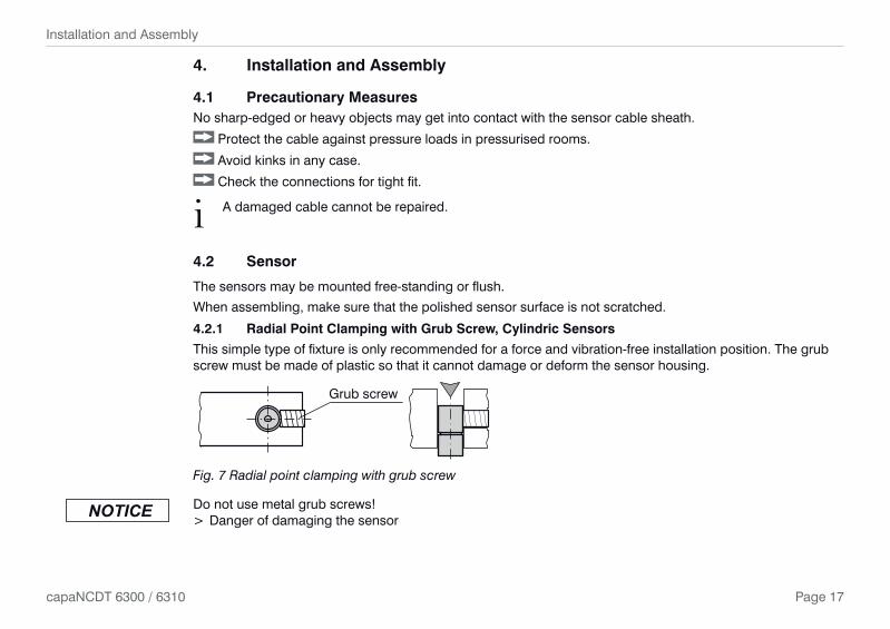
4.2.1 Radial Point Clamping with Grub Screw, Cylindric Sensors
This simple type of fixture is only recommended for a force and vibration-free installation position. The grub screw must be made of plastic so that it cannot damage or deform the sensor housing.
Grub screw
Fig. 7 Radial point clamping with grub screw
Do not use metal grub screws! > Danger of damaging the sensor

Page 18
Installation and Assembly
capaNCDT 6300 / 6310
4.2.2 Circumferential Clamping, Cylindric Sensors
This sensor mounting option offers maximum reliability because the sensor is clamped around its cylindrical housing. It is absolutely necessary in difficult installation environments, for example on machines, production plants et cetera.
Mounting with clamping ring
Fig. 8 Circumferential clamping
i Tension at the cable is inadmissible!
4.2.3 Flat Sensors
Flat sensors are mounted by means of a tap hole for M2 (in case of sensors 0.2 and 0.5 mm) or by a through hole for M2 screws. The sensors can be bolted on top or below.
Screwing from above Screwing from bottom

Page 19
Installation and Assembly
capaNCDT 6300 / 6310
4.2.4 Dimensional Drawings Sensors
Connector side ø10f7 (.394 dia.)
CS1HP
15 1
(.59
0)
20 -0
,2
(.7
87 -0
08 )
CS02
12
(.47
2)
ø6f7 (.236 dia.)8
1 (.
315)
12
(.47
2)
CS005
ø6f7 (.236 dia.)
ø3 (0.118 dia.)
ø8f7 (.314 dia.)
CS05
8 1
(.31
5)12
(.
472)
8 1
(.31
5)11
(.4
33)
15 (
.590
)
CS08
ø10f7 (.394 dia.)
ø10f7 (.394 dia.)
CS1
21
-0
,2
(.8
26 -0
08)
17
1 (.
66
9)
M=1:2ø20h7 (.79 dia.)
24 -0
.2
(.94
5) -0
.08
Connector side
CS2
ø30h7 (1.18 dia.)
ø20h7 (.79 dia.)
24 -0
,2
(.94
5) -0
.08
CS3
M=1:2
ø20h7 (.79 dia.)
ø40h7 (1.58 dia.)
CS5
M=1:2
16.5
1
24 -0
,2
ø20h7 (.79 dia.)
ø60h7 (2.36 dia.)
M=1:2
CS10
20 1 (
.787
)
16.5
1 ( .6
49)
16.5
1 ( .6
49)
24 -0
,2
(.94
5) -0
.08
1) Adjustment area for radial point respectively circumferential clamping
DimensionFit
tolerance
6e7-20-32
6h60-8
6f7-1022
8f7-13-28
10f7-13-28
20h70
-21
30h70
-21
40h70
-25
60h70
-30
1 µm = 0.001 mm = 1 micron

Page 20
Installation and Assembly
capaNCDT 6300 / 6310
CSE05
12 (
.47)
ø6f7(.24 dia.)
ø5.7 (.22)
9 (.
35)
CSE1
12 (
0.47
)
ø8f7 (0.31 dia.)
CSE2
ø14h7 (0.55 dia.)
18.5
(0.
73)
22 (
0.87
)
ø7.7 (0.30 dia.)
9 (0
.35)
ø13.7 (0.54 dia.)
Connector side
200 (7.87)
9.9 (0.39)
15(0
.59)
20.2
(0
.80)
1 (0.04) Sensor structuresThickness 0.9-0.05 (0.04 -0.002)
216 (8.5)
R2
CSG0.50-CAm2.0 and CSG1.00-CAm2.0
Sensor structures
2.9(0.11)
4.2
(0.1
7)
4.5(0.18)
5.4
(0.2
1)
4.2 (0.17)
6.2
(0.2
4)
3.85(0.15)
4.4
(0.1
7)
CSG0.50-CAm2.0 CSG1.00-CAm2.0 Dimensions in mm (inches), not to scale

Page 21
Installation and Assembly
capaNCDT 6300 / 6310
ø12g6 (.473 dia.)
CSH1, CSH1.2
14
(.39
)33
(1
.30)
ø11.5(.45 dia.)
10 1
(.39
)
ø2.2 (.09 dia.)
ca. 3
7 (1
.46)
ca. 9.4 (.37)
ø8g6 (.315 dia.)
CSH02, CSH05
ø7.5 (.30 dia.)
14
(.39
)33
(1
.30)
10 1
(.39
)ø2.2 (.09 dia.)
ca. 3
7 (1
.46)
ca. 9.4 (.37)
Dimensions in mm (inches), not to scale
1) Adjustment area for radial point respectively circumferential clamping
Page 22
Installation and Assembly
capaNCDT 6300 / 6310
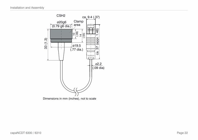
ø20g6(0.79 g6 dia.)
33 (
1.3)
14 (.55
)
10 (
.39)
ø19.5(.77 dia.)
Clamparea
CSH2
ø2.2(.09 dia)
ca. 3
7 (a
ppr.
1.46
)
ca. 9.4 (.37)
Dimensions in mm (inches), not to scale

Page 23
Installation and Assembly
capaNCDT 6300 / 6310
M23.5
(.14
)4
(.16
)
5.5(.22)
R4 (.16)
CSH02FL, CSH05FL
6.5
(.25
)
4 (.16)0.1 (.003)
ø3(.12 dia.)
1.75
(.07
)
ø2.2(.09 dia.)
ca. 3
7 (1
.46)
ca. 9.4 (.37) CSH1FL, CSH1.2FL
11 (
.43)
2.25
(.09
)
4.5
(.18
)5
(.20
)
7.5(.29)
R6(.24)
ø3(.12 dia.)
0.1(.003)
4 (.16)
ø2.5
(.10
)
ø4 (.16
dia
.)
ø2.2(.09 dia.)
ca. 3
7 (1
.46)
ca. 9.4 (.37)
Dimensions in mm (inches), not to scale

Page 24
Installation and Assembly
capaNCDT 6300 / 6310
CSH2FL
20 (.79)15.5 (.61)
15.5
(.6
1)20
(.7
9)
ø3(.12 dia.)
ø2.2(0.09 dia.)
ca. 3
7 (1
.46)
ca. 9.4 (.37)
0.1(.004)
5 (.20)
ø2.2
(.09
dia
)
1.6 (.06)
ø4 (
.16
dia)
7.6
(.30
)
Dimensions in mm (inches), not to scale
Page 25
Installation and Assembly
capaNCDT 6300 / 6310
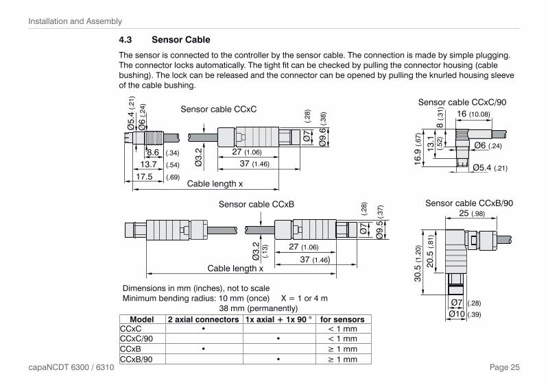
4.3 Sensor Cable
The sensor is connected to the controller by the sensor cable. The connection is made by simple plugging. The connector locks automatically. The tight fit can be checked by pulling the connector housing (cable bushing). The lock can be released and the connector can be opened by pulling the knurled housing sleeve of the cable bushing.
Ø9.
6 (.
38)
Cable length x17.5 (.69)
13.7 (.54)
8.6 (.34)
Ø6
(.24
)
Ø5.
4 (.
21)
Ø3.
2
37 (1.46)
27 (1.06)
Ø7
(.2
8)Sensor cable CCxC 16 (10.08)
Ø6 (.24)
Ø5.4 (.21)
8 (.
31)
13.1
(.52
)
16.9
(.67
)
Sensor cable CCxC/90
Cable length x
Ø3.
2(.
13) 27 (1.06)
37 (1.46)
Ø7
(.2
8)
Ø9.
5 (.
37)Sensor cable CCxB
Dimensions in mm (inches), not to scale Minimum bending radius: 10 mm (once) X = 1 or 4 m 38 mm (permanently)
25 (.98)
20.5
(.81
)
30.5
(1.2
0)
Ø7 (.28)
Ø10 (.39)
Sensor cable CCxB/90
Model 2 axial connectors 1x axial + 1x 90 ° for sensorsCCxC • < 1 mmCCxC/90 • < 1 mmCCxB • ≥ 1 mmCCxB/90 • ≥ 1 mm

Page 26
Installation and Assembly
capaNCDT 6300 / 6310
4.4 Preamplifier CP6001
34.6(1.36)
85.6
(3.3
7)
73 (2
.87)
42 (1
.65)
11.5
(453
)
114 (4.49)8 (.36)
4.5 (.18)
Sen
sor
Con
trol
ler
Fig. 9 Preamplifier CP6001, dimensions in mm, not to scale
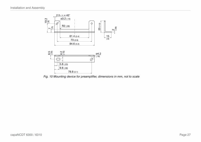
Mounting preamplifier with mounting device (CP6001) Remove the four black protecting caps at the housing screws, dimension 73.
Remove the four housing screws.
Fix the both mounting devices at the preamplifier. Use the screws contained in the delivery.
Page 27
Installation and Assembly
capaNCDT 6300 / 6310
5.8 (.23)
8.5
(.34
)7 (.
3)
19.3
(.8)
25 (
1.0)
4.2
(.16
)
ø4.2(.16)
9.8 (.38)
78.8 (3.1)
61.4 (2.4) 15(.6)
2.5 (.1) x 45°ø3.2 (.13)
R2 (.08)
73 (2.9)
84.6 (3.3)
2 (.08
)
Fig. 10 Mounting device for preamplifier, dimensions in mm, not to scale

Page 28
Installation and Assembly
capaNCDT 6300 / 6310
4.5 Preamplifier Cable
Ø 8
.9 (
.35
dia.
) SW8
~35~25
Ø 4
.3±
3 m
m(.
19 d
ia.)
x = cable length 5 ... 25 m (standard 5 m)
Dimensions in mm Inches), not to scale
Model Cable length Min. bending radius, permanentCA5 5 m
33 mCA10 10 mCA20 20 mCA25 25 m

Page 29
Installation and Assembly
capaNCDT 6300 / 6310
4.6 Controller
PO
WE
R IN
SE
NS
OR
/CP
SIG
NA
L OU
TP
OW
ER
/SY
NC
44.7 (1.76) 13(.51)
4(.16)
155 ((6.10)
97 (
3.82
)
175 (6.89)
4x Mounting holes forscrews M4 x 45 (min.)
ø4.6 (.18)
ø8 (.32)
110
(4.3
3)
Dimensions in mm (inches), not to scale
Page 30
Installation and Assembly
capaNCDT 6300 / 6310
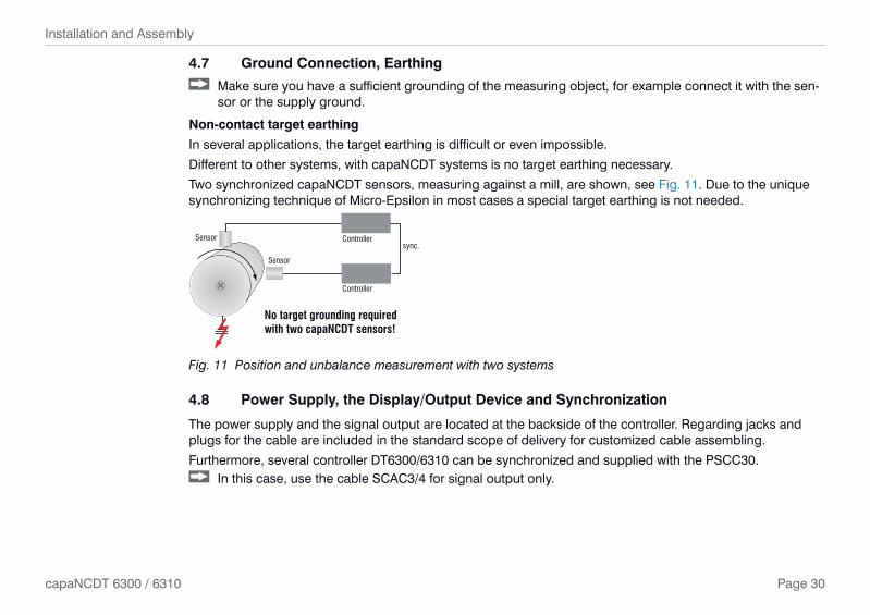
4.7 Ground Connection, Earthing
Make sure you have a sufficient grounding of the measuring object, for example connect it with the sen-sor or the supply ground.
Non-contact target earthing
In several applications, the target earthing is difficult or even impossible.
Different to other systems, with capaNCDT systems is no target earthing necessary.
Two synchronized capaNCDT sensors, measuring against a mill, are shown, see Fig. 11. Due to the unique synchronizing technique of Micro-Epsilon in most cases a special target earthing is not needed.
sync.ControllerSensor
Sensor
Controller
No target grounding requiredwith two capaNCDT sensors!
Fig. 11 Position and unbalance measurement with two systems
4.8 Power Supply, the Display/Output Device and Synchronization
The power supply and the signal output are located at the backside of the controller. Regarding jacks and plugs for the cable are included in the standard scope of delivery for customized cable assembling.
Furthermore, several controller DT6300/6310 can be synchronized and supplied with the PSCC30. In this case, use the cable SCAC3/4 for signal output only.

Page 31
Installation and Assembly
capaNCDT 6300 / 6310
POWER IN SENSOR/CP SIGNAL OUT POWER/SYNC POWER IN SENSOR/CP SIGNAL OUT POWER/SYNC
Externaldisplay
CP6001(capaNCDT6310)
PS100/230/15±15 VDC/500 mA
Sensor
SCAC3/4z.B. CA5
PC3/8
PSCC30
z.B. CC1B
Fig. 12 System assembly and synchronization with a second controller
Synchronization in multi-channel modeSeveral measuring systems capaNCDT 6300/6310 can simultaneously be used as multi-channel system. With the synchronization of the systems, a mutual influence to the sensors is avoided:
Plug the synchronize cable PSCC30 (accessory) into the jack POWER/SYNC at controller 1.
Plug the second end of PSCC30 into the jack POWER IN at the second controller. - The oscillator of controller 2 switches automatically into synchronization, this means, depending on the
oscillator of controller 1. - An influence of poor earthed target is excepted.
Where necessary, synchronize more measuring systems with the cable PSCC30.
i To ensure perfect synchronization, the master with the highest serial number must always be used!
Page 32
Installation and Assembly
capaNCDT 6300 / 6310
4.9 Pin Assignment
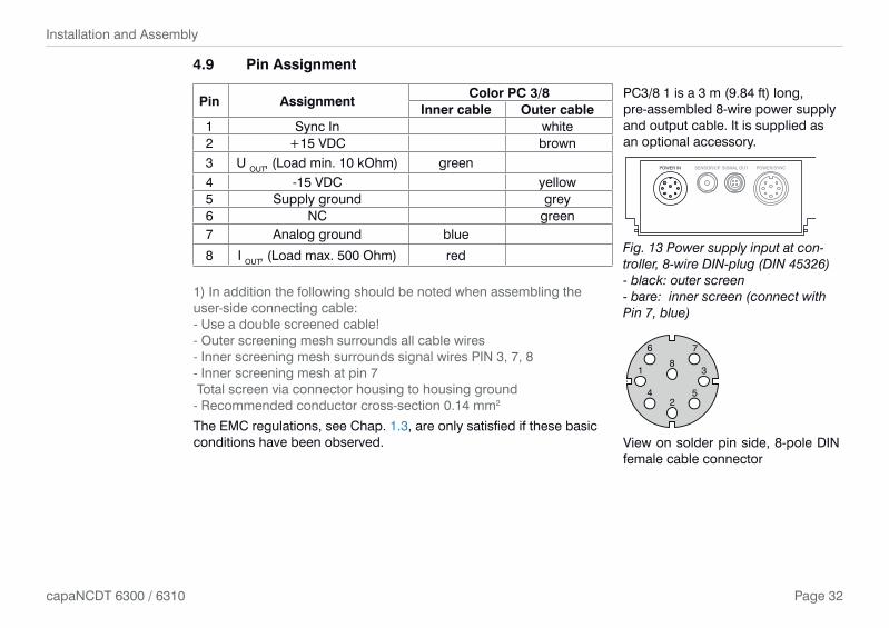
Pin AssignmentColor PC 3/8 PC3/8 1 is a 3 m (9.84 ft) long,
pre-assembled 8-wire power supply and output cable. It is supplied as an optional accessory.
POWER IN SENSOR/CP SIGNAL OUT POWER/SYNC
Fig. 13 Power supply input at con-troller, 8-wire DIN-plug (DIN 45326) - black: outer screen - bare: inner screen (connect with Pin 7, blue)
Inner cable Outer cable1 Sync In white2 +15 VDC brown3 U OUT, (Load min. 10 kOhm) green4 -15 VDC yellow5 Supply ground grey6 NC green7 Analog ground blue
8 I OUT, (Load max. 500 Ohm) red
1) In addition the following should be noted when assembling the user-side connecting cable:- Use a double screened cable!- Outer screening mesh surrounds all cable wires- Inner screening mesh surrounds signal wires PIN 3, 7, 8- Inner screening mesh at pin 7 Total screen via connector housing to housing ground- Recommended conductor cross-section 0.14 mm2
The EMC regulations, see Chap. 1.3, are only satisfied if these basic conditions have been observed.
1
2
3
4 5
6 7
8
View on solder pin side, 8-pole DIN female cable connector
Page 33
Installation and Assembly
capaNCDT 6300 / 6310
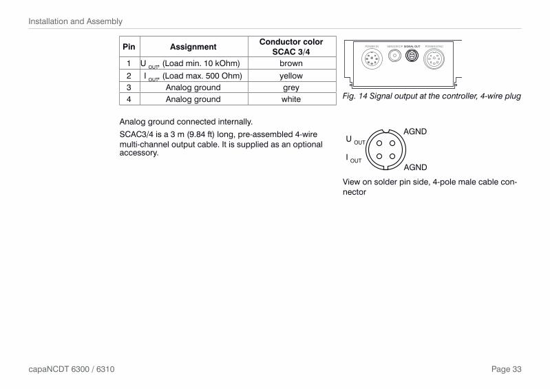
Pin AssignmentConductor color
SCAC 3/4POWER IN SENSOR/CP SIGNAL OUT POWER/SYNC
Fig. 14 Signal output at the controller, 4-wire plug
1 U OUT, (Load min. 10 kOhm) brown
2 I OUT, (Load max. 500 Ohm) yellow3 Analog ground grey4 Analog ground white
Analog ground connected internally.
SCAC3/4 is a 3 m (9.84 ft) long, pre-assembled 4-wire multi-channel output cable. It is supplied as an optional accessory.
AGND
AGNDI OUT
U OUT
View on solder pin side, 4-pole male cable con-nector

Page 34
Installation and Assembly
capaNCDT 6300 / 6310
Pin AssignmentWire color PSCC 30 PSCC 30 is a 0,3 m (0.98 ft) long,
pre-assembled power and synchroniza-tion cable. It is supplied as an optional accessory.
POWER IN SENSOR/CP SIGNAL OUT POWER/SYNC
Fig. 15 Outputs for synchronization, 8-pole DIN-jack (DIN 45326)
Inner cable Outer cable1 Sync OUT white2 +15 VDC brown3 NC green4 -15 VDC yellow5 Supply ground green6 NC green7 Analog ground blue8 NC red
1
2
3
45
67
8
View on solder pin side, 8-pole DIN male cable connec-tor
1
2
3
4 5
6 7
8
View on solder pin side, 8-pole DIN female cable con-nector

Page 35
Operation
capaNCDT 6300 / 6310
5. Operation
5.1 Starting Up
Connect the the display/output devices through the signal output socket, see Chap. 4.8, see Chap. 4.9, before connecting the device to the power supply and switching on the power supply.
i Allow the measuring system to warm up before the first measurement or calibration: DT 6300: ca. 10 min. DT 6310: ca. 30 min.
5.2 Basic Settings
The gain, zero and linearity point of the measuring channel are adjusted with the ’GAIN’, ’ZERO’ and ’LIN’ trimmer potentiometers, see Fig. 16, (the setting range is approximately 15 turns per potentiometer).
The end settings at the left and right stops are recognizable by a slight click.
ZERO LIN GAIN
STATUS
RANGE
ZERO
Zero point Linearity AmplificationLED Color Function
STATUSController failure
orange Controller OK
RANGEgreen Target in measuring rangered Target out of measuring range
ZEROFactory setting
redController operates with chan-ged factory setting
Fig. 16 Control elements at the controllerDisconnect the power supply before touching the sensor surface.
> Static discharge
> Danger of injury
The potentiometer are ex works at the right stop (maximum level).

Page 36
Operation
capaNCDT 6300 / 6310
Trimmer Setting
Zero: Shifts the output signal in negative direction to left.
Lin: Reduce the quadrate component by turning the trimmer to left.
Gain: Reduce the characteristic line slope by turning the trimmer to left.
Lin and Gain only are active by insulating measurement.
Position 1
Position 2
Choice of target
Choose with a slide switch, see Fig. 17, between conducting and nonconducting target.
In position 2 zero point setting with the zero trim-pot is active only. Gain is set to 0 up to 10 V through the whole measuring range.
Position 1 (Insulator), non-conducting
Position 2 (Metal), conducting
Fig. 17 Electronics in the controller

Page 37
Operation
capaNCDT 6300 / 6310
5.3 Calibration with Metal Targets
Preconditions: - Specific resistance of the target < 1 kΩcm. - Slide switch on the demodulator in position 2 (metals, see Fig. 17).
For metallic targets the demodulator´s linearization function is switched off since a linear characteristic is already available automatically on account of the measuring principle and sensor construction.
The measuring device is set to a sensitivity of 10 Volts corresponding to the measuring range of each sensor model.
The electrical zero point can be set across the whole measuring range with the .zero. potentiometer of the demodulator module. The start of the measuring range (= mechanical zero point) is on the front face of the sensor.
A tilted sensor or measuring object results in a reduced measuring range and zero point shifting according to the tilting.
Curved target surfaces cause linearity reductions if the distance between the sensor and the target is small.
Also with small target surfaces losses in linearity and sensibility occur.
Extension of the measuring range:
The sensor measuring ranges by metal measurement can be extended considerably (by a factor of 2-3) with some loss in linearity and sensitivity.
To do this, move the slide switch on the demodulator board to position 1.
Make the necessary linearity adjustment, see Chap. 5.4.
In step 1 here the following potentiometer setting is assumed: - zero: right stop - gain: left stop - linearity: right stop
Carry out the complete calibration up to step 4.

Page 38
Operation
capaNCDT 6300 / 6310
5.4 Linearity Adjustment and Calibration with Insulator Targets
Preconditions: - Specific resistance of the target > 10 6 Ωcm. - Slide switch on the demodulator in position 1
The measuring channel must be individually linearized and calibrated prior to measurements against insu-lator targets. Adjustment takes place at defined distances which are prescribed by a reference. A special micrometer calibration device with a non-rotating micrometer spindle (for example MC25 from MICRO-EPSI-LON) has proved to be particularly suitable. Spacer discs are not suitable.
The following parameters influence the calibration. Later operating conditions should be simulated as accu-rately as possible for the calibration. If one of these parameter changes, recalibration is recommended:
- Resistivity of the target - Dielectric constant of the target - Shape and thickness of the insulator - With thin targets, metal behind the target may influence the propagation of the field lines.
The greater the relative dielectric constant, the higher is the sensitivity of the measurement system.
Step 1:
Settings: .zero. right stop, .gain. middle, .linearity. middle
Record the measuring curve of the sensor at least 10 points.
Choose a range of low and as constant as possible curvature from this curve and determine the points: - A Start of measuring range - B Centre of measuring range - C End of measuring range
The output signal at point C should not exceed 10 V in the chosen measuring range. If necessary, the sensitivity can be reduced with the .gain. potentiometer.
A
B
C
B-A
C-B
C-A
Signal
Displacement
Fig. 18 Define the active measuring range

Page 39
Operation
capaNCDT 6300 / 6310
Step 2: Linearity
The measured value differences B-A and C-B are calculated from the fixed measuring points A B C and compared with each other. The setting of the .linearity. potentiometer is now altered until B-A and C-B are identical.
If the setting is not valid, you can do the following: Add with the trimmer .linearity. a quadratic component to the characteristic, which compensates the
physical not linear element of insulators.
In position zero (left stop) no quadratic component is added. If the value C exceeds 10 V reduce the sensitivity (.gain.).
If the .linearity. potentiometer is at the stop and B-A and C-B are still not equal, points A and C have probably been badly chosen.
Start again with step 1.
Step 3: Sensitivity In order to set a practicable sensitivity, first form the signal difference C-A and select a sensitivity which
matches the measuring range (for example 1 V/mm).
Calculate the required measured value C’ and set the distance point C.
C’ = C E
(C - A)
E ... desired signal span point A to C
C ... signal value at distance point C
A ... signal value at distance point A
If C’ is not more than 10 V, set it with the .gain. potentiometer.
As a final check, run through the whole measuring curve and document it.

Page 40
Operation
capaNCDT 6300 / 6310
Step 4: Zero point
The electrical zero point can now be shifted without af-fecting the linearity and sensitivity.
Sensor
Targ
et
0
1/1
Sig
nal
0 1/10.5Measuring range
Fig. 19 Signal behavior of the output voltage
5.5 Changing Limit Frequency
The controller operates with a limit frequency of 8 kHz (factory setting). In the case that the limit frequency is reduced, the output signal is filtered more efficiently and the resolution is therefore improved. At the same time the dynamic of the system is reduced.
Procedure for changing the limit fre-quency:
Open the controller.
Set the requested limit frequency us-ing the micro-switch, see Fig. 20.
Close the controller.
Fig. 20 Limit frequency
Page 41
Measurement
capaNCDT 6300 / 6310
6. Measurement
With the capaNCDT either the deflection or the compensation method of measurement can be applied. - Deflection method for fast events, tolerance monitoring and for insulators:
Put the zero point in the centre of the measuring range, the output signal is then in proportion to the distance. Fast events are displayed on a suitable external recorder (oscilloscope, recorder, transient recorder).
- Compensation method for constant or slowly changing distances.
Compensation is carried out with the .zero. potentiometer until the output signal is 0 Volt. Sensitivity is not affected by doing this.
7. Operation and Maintenance
Please take care of the following: Make sure that the sensor surface is always clean.
Switch off the power supply before cleaning.
Clean with a damp cloth; then rub the sensor surface dry.
Changing the target or very long operating times can lead to slight reductions in the operating quality (long term errors). These can be eliminated by recalibration, see Chap. 5.3, see Chap. 5.4.
Disconnect the power supply before touching the sensor surface. > Static discharge
> Danger of injury
In the event of a defect in the controller, the sensor or the sensor cable, the parts concerned must be sent back for repair or replacement. In the case of faults the cause of which is not clearly identifiable, the whole measuring system must be sent back for repair or replacement to
MICRO-EPSILON MESSTECHNIK GmbH & Co. KGKönigbacher Straße 15 94496 Ortenburg / Germany

Page 42
Liability for Material Defects
capaNCDT 6300 / 6310
8. Liability for Material Defects
All components of the device have been checked and tested for functionality at the factory. However, if de-fects occur despite our careful quality control, MICRO-EPSILON or your dealer must be notified immediately.
The liability for material defects is 12 months from delivery. Within this period, defective parts, except for wearing parts, will be repaired or replaced free of charge, if the device is returned to MICRO-EPSILON with shipping costs prepaid. Any damage that is caused by improper handling, the use of force or by repairs or modifications by third parties is not covered by the liability for material defects. Repairs are carried out exclu-sively by MICRO-EPSILON.
Further claims can not be made. Claims arising from the purchase contract remain unaffected. In particular, MICRO-EPSILON shall not be liable for any consequential, special, indirect or incidental damage. In the inter-est of further development, MICRO-EPSILON reserves the right to make design changes without notification.
For translations into other languages, the German version shall prevail.
9. Decommissioning, Disposal Remove the cable for electrical power and output signal on the controller.
Incorrect disposal may cause harm to the environments. Dispose of the device, its components and accessories, as well as the packaging materials in compli-
ance with the applicable country-specific waste treatment and disposal regulations of the region of use.
Page 43
Accessories, Service
capaNCDT 6300 / 6310
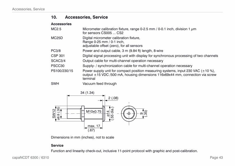
10. Accessories, Service
AccessoriesMC2.5 Micrometer calibration fixture, range 0-2.5 mm / 0-0.1 inch, division 1 µm for sensors CS005 ... CS2 MC25D Digital micrometer calibration fixture, Range 0-25 mm / 0-1 inch, adjustable offset (zero), for all sensorsPC3/8 Power and output cable, 3 m (9.84 ft) length, 8-wire CSP 301 Digital signal processing unit with display for synchronous processing of two channelsSCAC3/4 Output cable for multi-channel operation necessaryPSCC30 Supply- / synchronization cable for multi-channel operation necessaryPS100/230/15 Power supply unit for compact position measuring systems, input 230 VAC (±10 %), output ±15 VDC /500 mA, housing dimensions 116x69x44 mm, connection via screw terminalSWH Vacuum feed through
SW
12ø8
.8 (
.35)
ø14
(.55
dia
.)
9(.
35)
2 (.08)
34 (1.34)
max. 17(.67)
M10x0.75
Dimensions in mm (inches), not to scale
Service
Function and linearity check-out, inclusive 11-point protocol with graphic and post-calibration.

MICRO-EPSILON MESSTECHNIK GmbH & Co. KG
Königbacher Str. 15 · 94496 Ortenburg / Germany
Tel. +49 (0) 8542 / 168-0 · Fax +49 (0) 8542 / 168-90
[email protected] · www.micro-epsilon.com
X9751161-A071028HDR
*X9751161-A07*
MICRO-EPSILON MESSTECHNIK