carbon origami: a method to fabricate lightweight carbon ...rodrigm/wp-content/... · origami, 3d...
TRANSCRIPT

Carbon, in press (2018) https://www.sciencedirect.com/science/article/pii/S0008622318302768
Carbon Origami: A Method to Fabricate Lightweight Carbon
Cellular Materials
Monsur Islam, Joshua Flach and Rodrigo Martinez-Duarte*
Multiscale Manufacturing Laboratory, Department of Mechanical Engineering, Clemson
University, Clemson, SC 29631, USA
Abstract
We present the fabrication of lightweight cellular carbon materials using an origami-inspired
technique. Complex, porous shapes are fabricated by carbonizing an origami structure made by
pre-creasing and manual folding a flat piece of pure cellulosic paper. This relatively simple process
yields carbon origami shapes that feature density as low as 0.014 ± 0.005 g/cm3, 0.93% the density
of bulk glassy carbon. Yet, the specific stiffness of this carbon origami and its capability to transfer
load compare advantageously to other lightweight cellular materials such as carbon nanotube
foams, graphene elastomers, metallic microlattices, silica aerogel, and carbon foams. Such
promising mechanical properties coupled to the high temperature resistance and excellent chemical
and electrochemical stability of carbon positions carbon origami as a candidate to fabricate
lightweight, multifunctional materials.
1. Introduction
A cellular material was defined by Gibson and Ashby as an interconnected network of solid struts
or plates forming the edges and faces of cells [1]. One can find both nature- and man-made cellular
materials with either periodic or stochastic internal structure. Examples of periodic cellular
materials found in nature are wood [2] and cork [3]. Trabecular bone [4], plant parenchyma [5]
and sponge [6] are few examples of a natural stochastic foam-like structure. In contrast, synthetic
materials with stochastic foam-like structure include silica aerogel [7,8], carbon nanotube (CNT)
* Corresponding author Email address: [email protected] (R. Martinez-Duarte)

Carbon, in press (2018) https://www.sciencedirect.com/science/article/pii/S0008622318302768
foams [9], graphene elastomers [10], metallic foams, polymer foams [11], and carbon foams
[12,13]. Man-made micro- and nanolattices have been reported recently out of different materials
[14–17], which represent an excellent example of periodic structures. The most important feature
of cellular materials is their much lower density compared to the bulk version of the same material.
Additionally, cellular materials offer an improved specific surface area and specific mechanical
strength. It is thus no surprise that cellular materials find application as lightweight structural
components [18], energy absorption materials [19], catalysts support [20], and performance filters
[21]. Cellular carbon materials are reported using different carbon allotropes such as CNT,
graphene, glassy carbon and carbons derived from organic precursors [9,10,17,22]. In general,
these materials feature interesting properties including low density, high specific compressive
strength, high temperature tolerances (~3000 °C in inert atmosphere), high surface area and
adjustable electrical and thermal conductivity [23]. Such properties have enabled the use of these
cellular carbon materials in thermal energy storage, adsorption of water vapor, electrochemical
measurements, heat sinks and catalyst support [22,24]. Here, we are interested on cellular carbon
materials derived by heat treating organic polymers. This is mainly due to the facility of shaping
the precursor instead of the carbon.
We report on the use of origami techniques to fabricate lightweight cellular carbon materials. In
origami, 3D complex architectures are fabricated from a flat piece of paper by folding the paper
along prescribed creases [25–27]. Origami is gaining significant scientific and technological
interest among the scientific community due to its potential to fabricate numerous intricate
architectural shapes of engineering value [28]. Here we emphasize the use of origami structures as
lightweight rigid structures. We use cellulose paper with a random structure as carbon precursor.
Starting with a flat piece of paper, we use origami techniques to crease and fold specific structures
that we then pyrolyze in an inert atmosphere. The resulting carbon origami features a stochastic
cellular microstructure and a designed macrostructure with characteristically thin cross section.
The carbon origami structures reported here feature a relative stiffness comparable to CNT foams
[9], graphene elastomers [10], metallic microlattices [15], carbon foams [13] and silica aerogel [7].
In this work, we present the characterization of the carbon microstructure resulting from
carbonizing paper and a discussion of its effect on the mechanical properties of the origami
structure. Although we present results using a specific kind of cellulosic paper, there is an immense
Carbon, in press (2018) https://www.sciencedirect.com/science/article/pii/S0008622318302768
potential to tailor the mechanical properties of carbon origami by tailoring the microstructure of
the precursor paper. We also address the effect of carbonization on the cellulose fibers and on the
origami structure in terms of structural shrinkage. We finish by showcasing the versatility of this
technique to make different origami structures of different sizes. The use of origami-based
techniques to manufacture carbon cellular materials has excellent scalability prospects. Due to the
maturity of the paper making industry, it is possible to produce relatively inexpensive, pure
cellulose paper rolls. These could be creased and folded after optimizing continuous embossing
and folding techniques, such as those used in the manufacturing of paper bags and paper filters.
Continuous heat treatment of the folded shapes can be implemented using belt conveyor or pusher
tunnel furnaces, common in the production of tile and other ceramic pieces.
2. Experimental
2.1 Fabrication of carbon origami
The fabrication process consisted of four steps illustrated in Figure 1: 1) design of crease pattern,
2) automatic pre-creasing, 3) manual folding and 4) carbonization. Pure cellulose chromatography
papers Fisherbrand Chromatography Paper, Cat. No. 05-714-1 with thickness of 0.19 mm or
Whatman 3MM Chromatography paper, Cat. No. 3030-6158 with a thickness of 0.34 mm were
used for this work. Although we are able to fabricate different origami patterns, we focused our
study on Miura-ori, a pattern that belongs to the family of rigid origami. In this case, the facets are
considered as rigid panels and creases are considered as hinges [29,30]. The geometry of Miura-
ori resembles a herringbone pattern and consists a series of convex “mountains” and concave
“valleys”. This origami tessellation has gained much attention among the engineering communities
because of its simplicity and mechanical properties such as high specific stiffness [31,32], impact
energy absorption [33,34], and negative Poisson’s ratio [35,36]. The Miura-ori pattern has been
employed in different applications including packaging of solar panels for space mission [37] and
deformable energy storage devices [38]. The pattern can be also found in nature in different forms
such as leaves [39,40], embryonic intestines [41] and insect wings [42].
2.1.1 Design of crease patterns
Carbon, in press (2018) https://www.sciencedirect.com/science/article/pii/S0008622318302768
Fig. 1a shows the crease pattern for a unit cell of a Miura-ori fold. The dotted and solid lines in the
unit cell represent the creases to create “valleys” on one side of the paper and “mountains” on the
other. The Miura-ori design used here featured 16 unit cells. A unit cell can be defined by the
design parameters h, l and α [30]. All the Miura-ori samples fabricated here featured an α of 75°
and a 3:5 ratio between h and l. Such specific ratio resulted from fitting 16 unit cells in a square.
We only varied the value of h from 3.1 mm (1/8 in) to 15.3 mm (5/8 in) as the size of the pieces
increased from 1 inch × 1 inch to 5 inch × 5 inch.
Although the focus of this paper was the Miura-ori structure, other origami structures were studied
to assess scalability and complexity of the process. We characterized the Waterbomb base and
Yoshimura origami structures. These designs also featured 16 unit cells. The Waterbomb base unit
cell was defined by the design parameter s. The Yoshimura unit cell was defined by the design
parameters x and y (Fig. 7b and 7c).
Individual crease patterns for “valleys” and “mountains” for all origami structures were designed
using Solidworks (Dassault Systems, Waltham, MA, USA). Examples of valleys and mountains
for Miura-ori are shown in Fig. 1b and c respectively. These design files enabled the automatic
pre-creasing detailed in the next section.
2.1.2 Automatic pre-creasing
We used a modified desktop cutting-plotter machine (Graphtec CE6000-40, Japan) to
automatically pre-crease the paper and facilitate folding. We replaced the cutting blade with an
empty, generic ballpoint pen with a ball diameter of 1.5 mm. Parameters of interest during pre-
creasing included speed of movement, acceleration, number of passes and pressing force of the
pen. After optimization (data not shown), we defined a speed of 12 cm/s, acceleration of 0.71 m/s2,
a force of 2.16 N, and three passes as the ideal parameters to achieve the targeted creasing that will
facilitate folding of the origami tessellation. An example of the pre-creased paper for Miura-ori in
such process is shown in Fig. 1d. Alignment of valleys and mountains was implemented using
marks that were automatically generated by the software of the cutting plotter and printed on the
paper. Pre-creased samples with any visible misalignment were discarded.
2.1.3 Manual folding

Carbon, in press (2018) https://www.sciencedirect.com/science/article/pii/S0008622318302768
Following Miura-ori techniques, folding was done manually to ensure facets adjacent to the
creases for the “valleys” were rotated into the paper, while the facets adjacent to the creases for
the “mountains” were rotated out of it [43]. An example of the folded paper Miura-ori is illustrated
in Fig. 1e. As indicated in Fig. 1e, the angle obtained after folding, α', was smaller than designed.
Hence, instead of 75° we obtained 43.75° ± 0.33°. Five paper Miura-ori were folded for each value
of design parameter h.
2.1.4 Carbonization
Once folded, the paper Miura-ori origami structures were carbonized in a tube furnace (TF1400,
Across International, USA) using a well characterized protocol [44–47]. Due to a limitation on the
size of the tube, the maximum dimension of the samples was 115 mm. The carbonization protocol
featured 5 steps: (1) heating from room temperature to 300 °C at 5 °C/min; (2) dwell at 300 °C for
30 min to allow the excess oxygen to escape the furnace; (3) heating from 300 °C to 900 °C at 5
°C/min; (4) dwell at 900 °C for 75 min; and (5) cooling down to room temperature at a cooling
rate of 5 °C/min. Process was done under a nitrogen atmosphere. An example of the resultant
carbon Miura-ori is shown in Fig. 1f. Shrinkage occurs, which yields a sharper folding angle, α'',
when compared to the angle α' present after folding.
Carbon, in press (2018) https://www.sciencedirect.com/science/article/pii/S0008622318302768
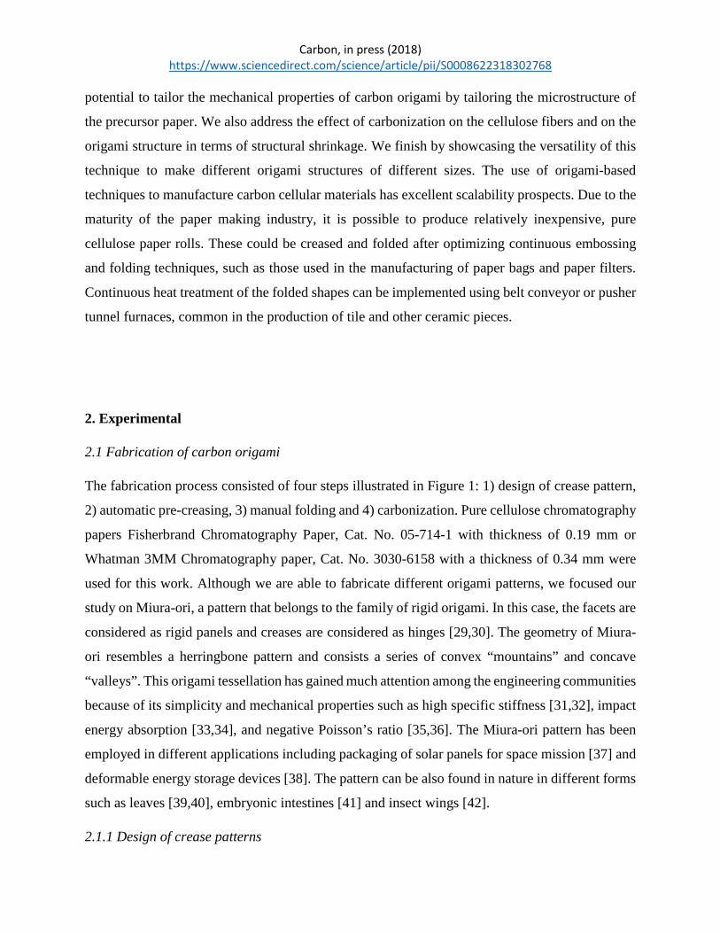
Figure 1: Fabrication process of carbon Miura-ori. (a) Unit cell of a Miura-ori pattern. The dotted
lines represent the “valleys” and the solid lines indicate the “mountains”. The unit cell is defined
by the characteristic design paremeters h, l and α. CAD software was used to create the crease
patterns for (b) “valleys” on one side and (c) “mountains” on the opposite side of the paper for
fabrication of Miura-ori. (d) Example of a 3 inch × 3 inch paper creased using a modified cutting
plotter. The unit cell of the Miura-ori pattern is indicated by the dashed rectangle, compare to (a).
(e) Paper Miura-ori obtained by manually folding the creased paper shown in (d). because of
manual folding, the design angle α decreased to the folding angle α'. (f) Carbon Miura-ori obtained
by heat treatment of the paper Miura-ori at 900 °C in nitrogen atmosphere. Although shrinkage
occurs, the shape is conserved. Because of the shrinkage, folding angle α' decreased to α'' for the
carbon Miura-ori.
2.2 Characterization
2.2.1 Material characterization
Carbon, in press (2018) https://www.sciencedirect.com/science/article/pii/S0008622318302768
The carbon miura-ori structure was characterized using X-ray diffraction (XRD, Rigaku Ultima
IV, Japan) spectroscopy to determine its crystallographic structure. Thermogravimetric analysis
(TGA) was performed to characterize weight loss during carbonization in nitrogen atmosphere
with a heating rate of 5 ºC/min. The microstructures of both the precursor paper and the resultant
carbon were using scanning electron microscopy (SEM, S4800, Hitachi, Japan). A thin carbon
film (10 nm) was sputtered on the precursor paper to facilitate its imaging. The microstructure of
the carbonized paper was further analyzed by high resolution transmission electron microscopy
(HRTEM, H9500, Hitachi, Japan). The pore size distribution of the carbonized paper was
characterized by image analysis of the SEM images using the particle analyzer, an inbuilt macro
in the ImageJ software.
2.2.2 Structure characterization
Following current practices in cellular materials, the structural density (ρ) of the carbon Miura-ori
structures was determined by the envelop method, which is the ratio between the mass of the
carbon Miura-ori and the total volume it occupied [9,48]. The compression tests of the carbon
Miura-ori structures were performed at a rate of 1 mm/min to 80% strain using an Instron Single
Column Testing System (Model 5944). A load cell of 50 N was used for the compression tests.
The stress-strain curve obtained in the compression test had three distinct regions: the elastic
region, post-yielding softening and densification [49,50]. We calculated the compressive strength
(σm) of the carbon Miura-ori sample as the onset point of fracturing of the panels, and the elastic
modulus (E) as the slope of the elastic region of the stress-strain curve. This elastic region is
characterized by the fact that the panels can stretch away from the creases to absorb the
compression force.
3. Results and Discussion
3.1 Compressive strength and Elastic Modulus depending on structural density
The structural density (ρ) of different carbon Miura-ori structures is plotted in Fig. 2a for different
lengths of the characteristic dimension h of a Miura-ori unit cell (see Fig. 1a). The density
Carbon, in press (2018) https://www.sciencedirect.com/science/article/pii/S0008622318302768
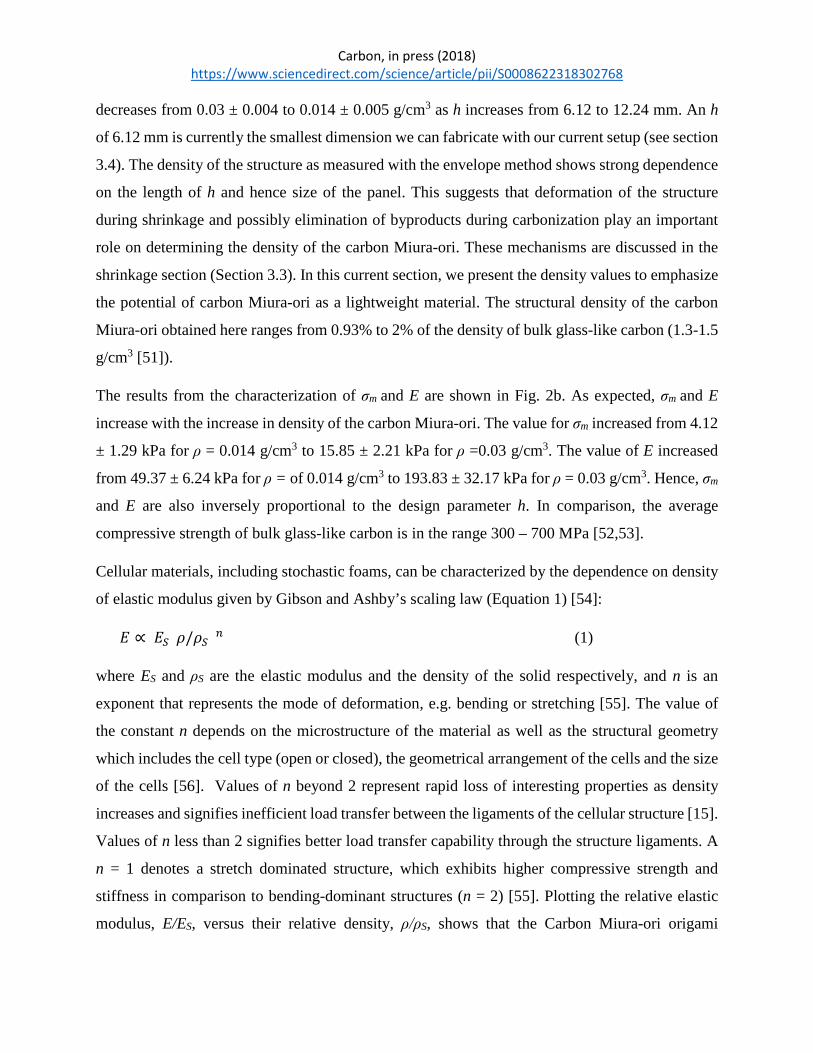
decreases from 0.03 ± 0.004 to 0.014 ± 0.005 g/cm3 as h increases from 6.12 to 12.24 mm. An h
of 6.12 mm is currently the smallest dimension we can fabricate with our current setup (see section
3.4). The density of the structure as measured with the envelope method shows strong dependence
on the length of h and hence size of the panel. This suggests that deformation of the structure
during shrinkage and possibly elimination of byproducts during carbonization play an important
role on determining the density of the carbon Miura-ori. These mechanisms are discussed in the
shrinkage section (Section 3.3). In this current section, we present the density values to emphasize
the potential of carbon Miura-ori as a lightweight material. The structural density of the carbon
Miura-ori obtained here ranges from 0.93% to 2% of the density of bulk glass-like carbon (1.3-1.5
g/cm3 [51]).
The results from the characterization of σm and E are shown in Fig. 2b. As expected, σm and E
increase with the increase in density of the carbon Miura-ori. The value for σm increased from 4.12
± 1.29 kPa for ρ = 0.014 g/cm3 to 15.85 ± 2.21 kPa for ρ =0.03 g/cm3. The value of E increased
from 49.37 ± 6.24 kPa for ρ = of 0.014 g/cm3 to 193.83 ± 32.17 kPa for ρ = 0.03 g/cm3. Hence, σm
and E are also inversely proportional to the design parameter h. In comparison, the average
compressive strength of bulk glass-like carbon is in the range 300 – 700 MPa [52,53].
Cellular materials, including stochastic foams, can be characterized by the dependence on density
of elastic modulus given by Gibson and Ashby’s scaling law (Equation 1) [54]:
𝐸𝐸 ∝ 𝐸𝐸𝑆𝑆(𝜌𝜌/𝜌𝜌𝑆𝑆)𝑛𝑛 (1)
where ES and ρS are the elastic modulus and the density of the solid respectively, and n is an
exponent that represents the mode of deformation, e.g. bending or stretching [55]. The value of
the constant n depends on the microstructure of the material as well as the structural geometry
which includes the cell type (open or closed), the geometrical arrangement of the cells and the size
of the cells [56]. Values of n beyond 2 represent rapid loss of interesting properties as density
increases and signifies inefficient load transfer between the ligaments of the cellular structure [15].
Values of n less than 2 signifies better load transfer capability through the structure ligaments. A
n = 1 denotes a stretch dominated structure, which exhibits higher compressive strength and
stiffness in comparison to bending-dominant structures (n = 2) [55]. Plotting the relative elastic
modulus, E/ES, versus their relative density, ρ/ρS, shows that the Carbon Miura-ori origami

Carbon, in press (2018) https://www.sciencedirect.com/science/article/pii/S0008622318302768
structures features a n =1.76 when considering the values for ES and ρS as 20 GPa and 1.5 g/cm3
for glass-like carbon respectively [17,57] (Fig. 2c). This value is close to 2 which suggests a
bending-dominant mechanical behavior similar to open cell cellular materials [1]. This was
expected for Miura-ori because of the random collection of 5.26 ± 2.53 µm-thick fibers in the
facets. Furthermore, Miura-ori in particular does not feature any strut at its basal plane, as in the
case of octet-trusses for example [14], which is a characteristic for stretch-dominated microlattices
[58]. A n = 1.76 also means that the carbon Miura-ori exhibits better scaling and better load
transferring capability than other cellular materials with higher values of n. For example, silica
aerogel and carbon nanotube (CNT) foams used for catalysts supports and energy storage
applications respectively feature a n = 3 [7,9]. Carbon aerogels derived through carbonization of
resorcinol-formaldehyde aerogel at 1100 °C feature a n = 2.7 at a porosity ranging from 80% to
95% [13]. Metallic microlattices feature a n = 2.4 [15], while graphene foams display a n = 2.5
[10]. Hence, the carbon Miura-ori structures presented here compare advantageously to other
common lightweight cellular materials in terms of scaling and load transfer capabilities. However,
the compressive strength of the carbon Miura-ori structures (4.12 kPa – 15.85 kPa) feature less
compressive strength than other structural materials with similar density such as metallic
microlattices (70 kPa – 3 MPa) [14] and carbon foam (~ 50 kPa) [13]. We hypothesize that the
random distribution of the open pores among the carbon fibers and the high standard deviation of
the fiber diameter are the reason for the low compressive strength. We provide further details on
the microstructure of the carbon fibers in section 3.2. Ongoing work is on using different pure
cellulose films with different microstructures. The control over smaller scales is expected to yield
a significant increase in compressive strength as recently reported by other authors [59].
Paper manufacturing involves pulping of wood chips followed by chemical treatment of the pulps,
mechanical pressing, and drying [60]. The microstructure of paper, i.e. fiber dimension and spatial
arrangement, depends on the source of the wood pulp, pulping method, treatment of the pulp and
the mechanical pressing [61]. Different microstructure of the paper can be obtained by controlling
these processing steps. For example, fibers from softwood feature slenderness ratio
(length/diameter) ranging from 95 to 120, whereas fibers from hardwood have slenderness ratio
ranging from 55 to 75 [61]. Higher slenderness ratio translates to a higher density of paper and
lower pore size distribution. Furthermore, paper made from thermomechanical pulping possesses
25-40% higher porosity than that made from chemical pulping [62]. The maturity of the paper

Carbon, in press (2018) https://www.sciencedirect.com/science/article/pii/S0008622318302768
industry represents an excellent stepping stone towards manufacturing carbon origami of tailored
properties. Once paper is obtained with specific microstructural properties, the continuous
processing for carbon origami will be enabled.
Figure 2: (a) Density (ρ) of carbonized Miura-ori of different sizes. At least five Miura-ori were
characterized for the shrinkage and the density for each value of h. The error bars represents the
standard deviation in the measurement. The red dashed line represents the best fitted curve to the
density. (b) Plots of compressive strength (σm) and elastic modulus (E) against density of the
carbon Miura-ori. The large standard deviations are attributed to the random distribution of carbon
fibers. (c) Relative elastic modulus (E/ES) of carbon Miura-ori with comparison to other low-
density materials.

Carbon, in press (2018) https://www.sciencedirect.com/science/article/pii/S0008622318302768
3.2 Characterizing the microstructure of carbon origami
The results from the XRD characterization of the carbonized paper (Fig. 3) show weak and broad
peaks centered around 2θ = 24° and 2θ = 43°, which are the characteristics of (002) and (100)
reflections of amorphous carbon [63,64].
Figure 3: XRD of the carbonized chromatography paper. The presence of peaks at 24 and 43°
indicate amorphous carbon.
The chromatography paper used in this work was basically a collection of tightly packed cellulose
fibers as shown in Fig. 4b. The average diameter of these fibers was 17.48 ± 3.06 µm. The carbon
obtained after heat treatment is shown in Fig. 4b. No impurities were observed on the carbon
matrix. This in contrast to significant impurities reported when carbonizing other paper types
which are not marketed as pure cellulose [65]. The fibers shrank to an average diameter of 5.26 ±
2.53 µm, resulting on an average linear shrinkage of fiber diameter of 69.89 ± 5.59%. The spacing
between fibers is of random nature leading to macroporosity of varying dimensions in the range
from 1.56 µm to 21.71 µm (inset of Fig 4b). The mechanical properties of a material are known to
depend on its microstructure [66]. Hence, the compressive strength (σm) and elastic modulus (E)
of the carbon Miura-ori would depend on the fiber composition, diameter and spacing between
them. We hypothesize that the high standard deviation in the carbon fiber diameter and random
Carbon, in press (2018) https://www.sciencedirect.com/science/article/pii/S0008622318302768
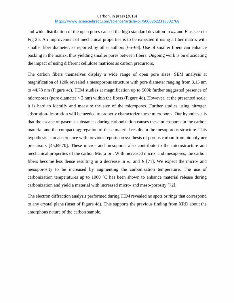
and wide distribution of the open pores caused the high standard deviation in σm and E as seen in
Fig 2b. An improvement of mechanical properties is to be expected if using a fiber matrix with
smaller fiber diameter, as reported by other authors [66–68]. Use of smaller fibers can enhance
packing in the matrix, thus yielding smaller pores between fibers. Ongoing work is on elucidating
the impact of using different cellulose matrices as carbon precursors.
The carbon fibers themselves display a wide range of open pore sizes. SEM analysis at
magnification of 120k revealed a mesoporous structure with pore diameter ranging from 3.15 nm
to 44.78 nm (Figure 4c). TEM studies at magnification up to 500k further suggested presence of
micropores (pore diameter < 2 nm) within the fibers (Figure 4d). However, at the presented scale,
it is hard to identify and measure the size of the micropores. Further studies using nitrogen
adsorption-desorption will be needed to properly characterize these micropores. Our hypothesis is
that the escape of gaseous substances during carbonization causes these micropores in the carbon
material and the compact aggregation of these material results in the mesoporous structure. This
hypothesis is in accordance with previous reports on synthesis of porous carbon from biopolymer
precursors [45,69,70]. These micro- and mesopores also contribute to the microstructure and
mechanical properties of the carbon Miura-ori. With increased micro- and mesopores, the carbon
fibers become less dense resulting in a decrease in σm and E [71]. We expect the micro- and
mesoporosity to be increased by augmenting the carbonization temperature. The use of
carbonization temperatures up to 1000 °C has been shown to enhance material release during
carbonization and yield a material with increased micro- and meso-porosity [72].
The electron diffraction analysis performed during TEM revealed no spots or rings that correspond
to any crystal plane (inset of Figure 4d). This supports the previous finding from XRD about the
amorphous nature of the carbon sample.

Carbon, in press (2018) https://www.sciencedirect.com/science/article/pii/S0008622318302768
Figure 4: FESEM image of chromatography paper (a) before and (b) after carbonization at a
magnification of 600X. The arrows indicate the diameter of the fibers. Diameters were measured
for at least ten fibers in both cases. The average diameter of the cellulose fibers in (a) was 17.48 ±
3.06 µm and that for carbon fibers in (b) was 5.26 ± 2.53 µm, resulting in an average linear
shrinkage of fiber diameter of 69.89 ± 5.59 %. Inset of (b) represents the pore size distribution of
the open pores. The diameter of the open pores ranges from 1.56 µm to 21.71 µm. (c) High
magnification FESEM image of the carbonized chromatography paper at a magnification of 120k
showing the mesoporous structure of the carbon fibers. Representative examples of the pores are
indicated by the arrows. Pore diameter ranges from 3.15 nm to 44.78 nm as shown in the inset. (d)
HRTEM image of the carbonized chromatography paper showing the micropores in the carbon
material. Examples of the micropores are indicated by the arrows. The electron diffraction pattern
in the inset shows no ring or spot, which confirms the amorphous nature of the carbon sample.

Carbon, in press (2018) https://www.sciencedirect.com/science/article/pii/S0008622318302768
3.3 Structural shrinkage
Thermogravimetric analysis (TGA) was performed to calculate the carbon yield of
chromatography paper. The results from the TGA are shown in Fig. 5 and are in accordance with
other authors [73–76]. A sharp weight loss occurs between 300 °C and 380 °C, which is attributed
to the thermal decomposition of cellulose in form of volatile components such as levoglucosan,
hydroxyacetaldehyde, acetol, CO and CO2 [77]. Above 380 °C, a gradual weight loss at
approximately 0.0097%/°C can be observed which is mainly caused by elimination of oxygen and
hydrogen in the form of CO, CO2 and CxHy [78]. The carbon yield at 900 °C in nitrogen atmosphere
for the chromatography paper used here is 4.4%, which is in agreement with previous reports [65].
Other types of paper, such as printing paper and Whatman filter paper, were reported to feature a
yield in the range of 3 – 23% [65,77]. The yield of 4.4% may seem to conflict with the ~70% linear
fiber shrinkage reported above. The theoretical linear shrinkage of the diameter of a solid carbon
fiber derived from cellulose is expected to be 79% when considering a 4.4% carbon yield and
assuming similar densities for both carbon and cellulose [79,80]. This value can be obtained by
equating the mass of a cellulose fiber per unit length (cross-sectional area times density) with that
of a carbon fiber featuring a diameter 0.044 times of the cellulose fiber. However, such calculation
does not consider the porosity of the fibers illustrated in Fig. 4. We expect the porosity to account
for the difference between the theoretical 79% and the observed 70% linear shrinkage. Further
studies are required to fully characterize the porosity and exact density of both cellulose and carbon
fibers.
The carbon yield is expected to change according to the heating environment. Inert gases
commonly used for carbonization include helium, nitrogen, argon and forming gas (Nitrogen and
5% Hydrogen). Su and Lua reported that the thermal conductivity of the gas has an important role
on the carbon yield [59]. They determined the convection heat transfer coefficient of helium,
nitrogen and argon using an equation correlating Nutshell number with Prandtl number at a volume
flow rate of 11.3 ml/min and an inside diameter of 23.55 mm for the tube furnace [59,81]. At 800
°C, they calculated the convection heat transfer coefficient of helium, nitrogen and argon to be
109.20, 18.89 and 12.79 W/m2K respectively. This suggests that a helium environment will result
in a lower carbon yield when compared to nitrogen and argon environments. Furthermore, Dickens
reported that the use of vacuum facilitates the evacuation of carbonization byproducts when

Carbon, in press (2018) https://www.sciencedirect.com/science/article/pii/S0008622318302768
compared to the use of inert gas atmospheres; which would translate to a lower carbon yield as
well [82]. Further work is needed to determine the convection heat transfer co-efficient of different
gases for our system and characterize the weight loss in such heating environment for Miura-ori.
Figure 5: TGA of chromatography paper with a heating rate of 5 °C/min in nitrogen atmosphere.
Around 90% weight loss occurs in the range 320 °C – 380 °C. A 4.4% carbon yield was obtained
at 900 °C.
The structural shrinkage of the Miura-ori structure is the result of processes at various length
scales: from micrometric fibers to centimetric structures. As a reference, the carbonization of a flat
piece of paper without the Miura-ori structure resulted in a curved carbon film (see insert in Fig.
6a). The possible reasons for such curved film include induced pressure by the volatile products
and associated swelling or blistering during the heat treatment, and the thermal contraction that
results during cooling [83–85]. We further speculate that the random distribution of the fibers
causes unequal stresses within the fibers during carbonization. However, further investigation is
needed to understand such phenomena. Remarkably, a paper piece of the same dimensions but
shaped as Miura-ori does not curve during carbonization (Fig. 6a). Our hypothesis is that the
dynamics of the Miura-ori structure facilitates the release of thermal stress and thermal contraction

Carbon, in press (2018) https://www.sciencedirect.com/science/article/pii/S0008622318302768
through shrinkage, which prevents it from curving. Interestingly, the amount of shrinkage in
different axis of the Miura-ori is different as shown in Fig. 6a. We calculated shrinkage using
Equation 2, where LPi and LCi are the dimensions of the paper Miura-ori and carbon Miura-ori
respectively in the i-axis. Most of the shrinkage occurs on the horizontal plane and in the direction
perpendicular to the characteristic dimension h. We denoted this direction as the Y-axis. The least
shrinkage happens in the X-axis, or the direction parallel to h. The shrinkage in X with respect to
h is constant, slightly variable in the case of Y-axis and significantly different for the Z-axis.
𝑆𝑆ℎ𝑟𝑟𝑟𝑟𝑟𝑟𝑟𝑟𝑟𝑟𝑟𝑟𝑟𝑟 (%) = 𝐿𝐿𝑃𝑃𝑃𝑃− 𝐿𝐿𝐶𝐶𝑃𝑃𝐿𝐿𝑃𝑃𝑃𝑃
(2)
The material loss during carbonization results in shrinkage of the fibers and this can be explained
by the elimination of byproducts from carbonization. We hypothesize that the origami structure
has an impact on the evacuation of byproducts. This is because the weight of a carbonized piece
of paper with the same dimension than the one used for Miura-ori but without creasing and folding
is 10–20% less than the carbon Miura-ori. During carbonization, the decomposition of cellulose
produces condense-phase product, which evaporates. The nitrogen gas flowing in the tube aids the
evaporation of the byproducts by increasing the mass transfer co-efficient [86]. However, in the
case of Miura-ori, it can be possible that the nitrogen gas cannot reach the intricate parts of the
Miura-ori uniformly. For example, disturbances in the laminar flow in the tube can be introduced
at the folding corners. This results in inefficient mass transfer from those intricate parts and volatile
intermediates may get enough time to crosslink and stay as a part of the solid. Therefore, a higher
mass is obtained for the carbon Miura-ori. Future work will be required to support this hypothesis
and characterize this phenomenon further.
The dynamics of the Miura-ori structure are likely to play a role in shrinkage. It is known that a
Miura-ori structure offers the least mechanical resistance in the Y-axis, followed by the Z-axis and
lastly the X-axis. The shrinkage reported here follows this trend in all samples (Fig. 6b). Shrinkage
of the fiber network during carbonization leads to pulling stresses that find the least resistance in
the Y- and Z-axis. Shrinkage also depends on the characteristic dimension h. As h increases, the
shrinkage in Y-axis slightly decreases and Z-axis slightly increases. The characterization of the
fold angle after carbonization (α'') of Miura-ori structures exposes the fact that α'' is directly
proportional to h (Fig. 6b). Hence, the unit cell of a Miura-ori is elongated during carbonization

Carbon, in press (2018) https://www.sciencedirect.com/science/article/pii/S0008622318302768
and this elongation increases as h decreases (plot of α'' in Fig. 6b). According to the geometry of
Miura-ori, the dimension in Y-direction is directly proportional to α'' and the dimension in Z-
direction is inversely proportional to α'' [36]. Hence, the dimension in Y-direction increases with
h resulting in decreasing shrinkage, whereas the dimension in Z-direction decreases with the
increase in h resulting in higher shrinkage. The results obtained here suggest a plateau on the
folding angle value α'' for h > 12.2 mm. However, further experiments in a bigger furnace than
ours are required to conclude on this. In order to assess the effect of the thickness of the precursor
paper, we compared the dimensions of i) paper Miura-ori folded with chromatography paper of
0.19 or 0.34 mm and the ii) resultant carbon origami after similar heat treatment of both paper
Miura-ori. The dimensions in paper were similar, and the amount of shrinkage during
carbonization remained the same in all directions regardless of the paper thickness (data not
shown). Since both papers featured similar pure cellulose fibers and fiber density, our hypothesis
is that the fibers experience similar material loss and thermal contraction force during the heat
treatment irrespective of the paper thickness.
The shrinkage behavior detailed above helps explain the decreasing density of the carbon Miura-
ori as h increases. An increasing value of h means that the size of the panels of the paper Miura-
ori structure increases. This effectively decreases the density of the Miura-ori by introducing larger
voids in the structure. Furthermore, shrinkage during carbonization results in retraction of the
panels towards each other, caused by the reduction of the folding angle as h decreases. The angle
between panels in the vertical plane is 44.08° ± 7.81°. The bigger the reduction on the folding
angle is, the higher the density of the structure becomes. Hence, small values of h yield increased
values of structural density. The plateau in α'' in Fig. 6b results in a plateau in structural density
reflected in Fig. 2a. As mentioned before, further experiments are needed with Miura-ori structures
with h > 16 mm to validate this observation.

Carbon, in press (2018) https://www.sciencedirect.com/science/article/pii/S0008622318302768
Figure 6: (a) Miura-ori before and after heat treatment. Note that the carbon structure retained the
Miura-ori pattern, whereas carbonization of a flat piece of paper results in a randomly curved piece
of paper as shown in the inset. Shrinkage occurs during the carbonization. In case of carbon Miura-
ori, maximum shrinkage occurs along Y-axis, followed by X- and Z-axis. (b) Shrinkage in X-, Y-
, and Z-direction for different sizes of Miura-ori. Maximum shrinkage occurred in Y-direction
followed by Z- and X-direction. The folding angle of the carbon Miura-ori (α'') was also plotted
for different sizes of Miura-ori. The error bars represents the standard deviation in the
measurement.
3.4 Versatility of the fabrication process
We performed studies to elucidate the minimal dimensions achievable in different origami
structures when using the manual fabrication technique presented here. The ultimate goal is to
automate folding techniques and this initial study is aimed at identifying challenges towards this

Carbon, in press (2018) https://www.sciencedirect.com/science/article/pii/S0008622318302768
goal. Previous authors attributed the failure of folding Miura-ori to the occurrence of folding
defects such as curl, crimps and kinks in the facets, which were due to bending and compressive
stresses exerted on the facets during manual folding [87]. Here we focused on elucidating the
impact of shape complexity on the minimal origami dimensions that are achievable by an average
human folder. We studied Miura-ori, Waterbomb base and Yoshimura (Fig. 7) to account for
different complexities. The upper limit on dimensions was given by the diameter of the furnace
tube used in this work (120 mm). Pre-creasing was achieved across all dimensions tested here
since the resolution of the pen, 1.5 mm, was smaller than the separation between all lines.
The complexity of the origami structure can be characterized by N, which is the ratio between the
number of crease lines and the area of paper. Miura-ori is the most complex, with highest N, shape
among the three studied here followed by Waterbomb base. This means that for a given paper area,
a Miura-ori fold features more crease lines. N can then be related to the characteristic size of the
different origami structures as given by their unit cell. In this work, the unit cell of Miura-ori is
characterized by h, the Waterbomb base by s and Yoshimura by y. For a given length of h, s and
y, a Miura-ori features a higher N. Results (Fig. 7d) indicate that the achievable structure depends
on the attempted shape and the characteristic size of its unit cell. The minimal length of the
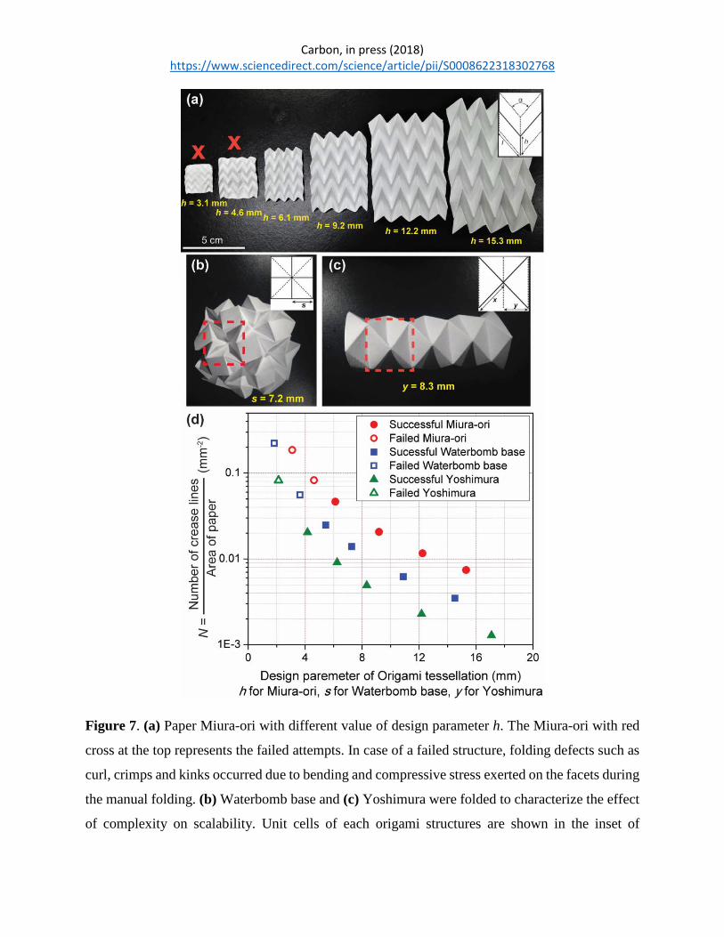
characteristic dimension to achieve an origami structure depends on the shape. A value of h ≤ 4.6
mm was not achievable in Miura-ori, while values of s ≤ 3.6 mm and y ≤ 2.1 mm were not possible
with Waterbomb based and Yoshimura respectively. In other words, Miura-ori requires the largest
size of paper area among the three shapes for a specific N. A value of N greater than 0.05 mm-2
failed for all the three shapes during the manual folding. At such value of N, the number of crease
lines per unit area of paper becomes so high that the distance between adjacent creases becomes
extremely close for manual folding. At such condition, the fold propagates beyond the prescribed
crease lines during manual folding and interferes with other adjacent crease lines. This results in
folding defects such as curl, crimps and kinks in the facets.
The upper limit of scalability for paper creasing in our case is entirely dependent on the capabilities
of the cutting plotter used to pre-crease the paper. The cutting plotter used in this experiment
features a maximum cutting area of 375 mm × 50 m. This large cutting area can permit large
patterned sheets to be created using the pre-creasing method as long as the features are scaled to
the appropriate size. However, large sheet of paper may be more difficult to control, especially

Carbon, in press (2018) https://www.sciencedirect.com/science/article/pii/S0008622318302768
during manual folding of the complex origami structures. In future large-scale manufacturing, the
manual folding can be avoided by using upcoming reprogrammable robots [88–90] or processes
akin to those used in the manufacturing of paper bags and filters [91]. This will eliminate the
dependence of dexterity of the user and likely allow for defect-free folding of the creased paper. It
could also allow for fabrication of origami shapes having N > 0.05 mm-2 and afford better control
while handling large sheets of paper. The use of embossing rollers [92–94] to automate the
continuous creasing of paper, and the use of rolling furnaces to carbonize origami structures
complement automatic folding towards large-scale manufacturing of carbon origami. Rolling
furnaces are already common practice in the manufacturing of tiles and other ceramic parts [95].
Carbon, in press (2018) https://www.sciencedirect.com/science/article/pii/S0008622318302768
Figure 7. (a) Paper Miura-ori with different value of design parameter h. The Miura-ori with red
cross at the top represents the failed attempts. In case of a failed structure, folding defects such as
curl, crimps and kinks occurred due to bending and compressive stress exerted on the facets during
the manual folding. (b) Waterbomb base and (c) Yoshimura were folded to characterize the effect
of complexity on scalability. Unit cells of each origami structures are shown in the inset of

Carbon, in press (2018) https://www.sciencedirect.com/science/article/pii/S0008622318302768
corresponding images and denoted by the red dotted square in the folded paper structures. The
number of crease lines per unit area of paper represents the complexity of the origami structures.
(d) Ratio of number of crease lines over area of paper were plotted for different sizes of Miura-
ori, Waterbomb base and Yoshimura. Note that manual folding fails over a number of crease lines
to area of paper ratio of 0.05 mm-2.
4. Concluding remarks
In this work, we demonstrated the fabrication of lightweight, rigid carbon cellular materials using
origami techniques. We automated the pre-creasing of flat pieces of cellulosic paper to facilitate
the manual folding of origami structures. 3D complex origami shapes of carbon were obtained
after carbonization. These featured a unique hierarchical porous microstructure as characterized
by SEM and TEM. Shrinkage occurred both in the micro- and macro-scales during the
carbonization due to the release of carbonization byproducts. The shrinkage in the macro-scale
also depended on the dynamics of the origami shape. The carbon structures featured low density,
comparable to other materials such as CNT foams and graphene elastomer that require more
complex fabrication processes. The Miura-ori cellular material displays a bending dominant failure
under compression (n = 1.76). The carbon Miura-ori exhibited low absolute compressive strength
and elastic modulus due to the random and wide distribution of the open pores. However, it
featured better scaling of relative stiffness when compared to other cellular engineering materials
such as silica aerogel, carbon aerogel, graphene elastomers, metallic microlattices and CNT foams.
This indicates better load transfer capability of the carbon Miura-ori when compared to these other
cellular engineering materials. The large scale manufacturing of carbon origami is envisioned to
include embossing rollers to pre-crease the paper, automatic folding using robots and continuous
heat treatment using rolling furnaces.
We postulate carbon origami as a technique to fabricate multifunctional cellular materials. Here
we demonstrated the initial mechanical properties of carbon Miura-ori structures. Further work is
necessary to improve these properties by controlling the microstructure of the carbon by tailoring
the structure of the precursor paper and heating protocols. The use of porous carbon in energy
applications such as batteries, fuel cells and capacitors is well known. In fact, cellulose derived
Carbon, in press (2018) https://www.sciencedirect.com/science/article/pii/S0008622318302768
carbon by itself or functionalized with metallic nanoparticles has been shown to have excellent
electrochemical responses preferable for applications such as batteries, capacitors, CO2 reductors
and fuel cells [96–99]. Further work to elucidate the effect of processing on the surface area and
electrochemical properties of carbon origami is necessary. Such studies will also further the use of
porous carbon for sensing [98]. The combination of the results emanating from electrochemical
and mechanical studies can lead to the development of origami structures with tailored mechanical,
energy and sensing properties. For example, lightweight structural capacitors and batteries that are
capable to sustain a mechanical load and can monitor their environment. The fact that such carbon
material has excellent chemical inertness and can sustain temperatures up to 500 °C under
oxidative environments [100] and up to 2500 °C in inert conditions [23] suggests their use in harsh,
high temperature applications such as structural filters in diesel engines [101] and during the
processing of certain molten materials [102].
Acknowledgements
The authors acknowledge financial support from the Creative Inquiry program in Clemson
University project #792. Monsur Islam acknowledges support from Hitachi through a High
Technologies Fellowship. The authors are grateful to several colleagues at Clemson University:
Dr. Taghi Darroudi from the Electron Microscopy (EM) Laboratory for his advice during image
acquisition; Dr. Laxmikant Saraf also from EM lab for his support of this work; Dr. Kimberly Ivy
from the Analytical Measurement Laboratory for facilitating TGA studies; Dr. Suyi Li from
Mechanical Engineering for discussion about origami designs; and to the Institute for Biological
Interfaces of Engineering for facilitating the mechanical testing.
References
[1] L.J. Gibson, M.F. Ashby, Cellular solids: Structure and properties, Second Edi,
Cambridge University Press, Cambridge, 1997.
[2] K. Ando, H. Onda, Mechanism for deformation of wood as a honeycomb structure I:
Effect of anatomy on the initial deformation process during radial compression*, J Wood
Sci. 45 (1999) 120–126. doi:10.1007/BF01192328.

Carbon, in press (2018) https://www.sciencedirect.com/science/article/pii/S0008622318302768
[3] L.J. Gibson, K.E. Easterling, M.F. Ashby, The structure and mechanics of cork, Proc. R.
Sociey London A. 377 (1981) 99–117.
[4] D. Chappard, M.F. Baslé, E. Legrand, M. Audran, Trabecular bone microarchitecture: A
review, Morphologie. 92 (2008) 162–170. doi:10.1016/j.morpho.2008.10.003.
[5] J.D. Gray, P. Kolesik, P.B. Høj, B.G. Coombe, Confocal measurement of the three-
dimensional size and shape of plant parenchyma cells in a developing fruit tissue, Plant J.
19 (1999) 229–236. doi:10.1046/j.1365-313X.1999.00512.x.
[6] Z. Lin, K.L. Solomon, X. Zhang, N.J. Pavlos, T. Abel, C. Willers, K. Dai, J. Xu, Q.
Zheng, M. Zheng, In vitro evaluation of natural marine sponge collagen as a scaffold for
bone tissue engineering, Int. J. Biol. Sci. 7 (2011) 968–977. doi:10.7150/ijbs.7.968.
[7] N. Leventis, C. Sotiriou-Leventis, G. Zhang, A.M.M. Rawashdeh, Nanoengineering
Strong Silica Aerogels, Nano Lett. 2 (2002) 957–960. doi:10.1021/nl025690e.
[8] T.M. Tillotson, L.W. Hrubesh, Transparent ultralow-density silica aerogels prepared by a
two-step sol-gel process, J. Non. Cryst. Solids. 145 (1992) 44–50. doi:10.1016/S0022-
3093(05)80427-2.
[9] M.A. Worsley, S.O. Kucheyev, J.H. Satcher, A. V. Hamza, T.F. Baumann, Mechanically
robust and electrically conductive carbon nanotube foams, Appl. Phys. Lett. 94 (2009) 1–
4. doi:10.1063/1.3086293.
[10] Z. Qin, G.S. Jung, M.J. Kang, M.J. Buehler, The mechanics and design of a lightweight
three-dimensional graphene assembly, Sci. Adv. 3 (2017) 1–8.
doi:10.1126/sciadv.160153.
[11] F. Scarpa, L.G. Ciffo, J.R. Yates, Dynamic properties of high structural integrity auxetic
open cell foam, Smart Mater. Struct. 13 (2004) 49–56. doi:10.1088/0964-1726/13/1/006.
[12] M. Letellier, C. Delgado-Sanchez, M. Khelifa, V. Fierro, A. Celzard, Mechanical
properties of model vitreous carbon foams, Carbon N. Y. 116 (2017) 562–571.
doi:10.1016/j.carbon.2017.02.020.
[13] R.W. Pekala, C.T. Alviso, J.D. LeMay, Organic aerogels: microstructural dependence of

Carbon, in press (2018) https://www.sciencedirect.com/science/article/pii/S0008622318302768
mechanical properties in compression, J. Non. Cryst. Solids. 125 (1990) 67–75.
doi:10.1016/0022-3093(90)90324-F.
[14] X. Zheng, H. Lee, T.H. Weisgraber, M. Shusteff, J. DeOtte, E.B. Duoss, J.D. Kuntz, M.M.
Biener, Q. Ge, J. a Jackson, S.O. Kucheyev, N.X. Fang, C.M. Spadaccini, Ultralight,
ultrastiff mechanical metamaterials., Science. 344 (2014) 1373–1377.
doi:10.1126/science.1252291.
[15] T. a. Schaedler, a. J. Jacobsen, a. Torrents, a. E. Sorensen, J. Lian, J.R. Greer, L.
Valdevit, W.B. Carter, Ultralight Metallic Microlattices, Science (80-. ). 334 (2011) 962–
965. doi:10.1126/science.1211649.
[16] J. Bauer, A. Schroer, R. Schwaiger, O. Kraft, Approaching theoretical strength in glassy
carbon nanolattices, Nat. Mater. 15 (2016) 438–443. doi:10.1038/nmat4561.
[17] A. Szczurek, A. Ortona, L. Ferrari, E. Rezaei, G. Medjahdi, V. Fierro, D. Bychanok, P.
Kuzhir, A. Celzard, Carbon periodic cellular architectures, Carbon N. Y. 88 (2015) 70–85.
doi:10.1016/j.carbon.2015.02.069.
[18] L. Valdevit, A.J. Jacobsen, J.R. Greer, W.B. Carter, Protocols for the optimal design of
multi-functional cellular structures: From hypersonics to micro-architected materials, J.
Am. Ceram. Soc. 94 (2011) 15–34. doi:10.1111/j.1551-2916.2011.04599.x.
[19] T.A. Schaedler, C.J. Ro, A.E. Sorensen, Z. Eckel, S.S. Yang, W.B. Carter, A.J. Jacobsen,
Designing metallic microlattices for energy absorber applications, Adv. Eng. Mater. 16
(2014) 276–283. doi:10.1002/adem.201300206.
[20] O.-Y. Kwon, H.-J. Ryu, S.-Y. Jeong, Porous layered carbon as catalyst support material
for PEMFC, J. Ind. Eng. Chem. 12 (2006) 306–310.
[21] R.A. Olson, L.C.B. Martins, Cellular ceramics in metal filtration, Adv. Eng. Mater. 7
(2005) 187–192. doi:10.1002/adem.200500021.
[22] M. Inagaki, J. Qiu, Q. Guo, Carbon foam: Preparation and application, Carbon N. Y. 87
(2015) 128–152. doi:10.1016/j.carbon.2015.02.021.
[23] C. Chen, E.B. Kennel, A.H. Stiller, P.G. Stansberry, J.W. Zondlo, Carbon foam derived
Carbon, in press (2018) https://www.sciencedirect.com/science/article/pii/S0008622318302768
from various precursors, Carbon N. Y. 44 (2006) 1535–1543.
doi:10.1016/j.carbon.2005.12.021.
[24] G. Tondi, a Pizzi, R. Olives, Natural Tannin-Based Rigid Foams As Insulation for Doors
and Wall Panels, Maderas. Cienc. Y Tecnol. 10 (2008) 219–227. doi:10.4067/S0718-
221X2008000300005.
[25] L.H. Dudte, E. Vouga, T. Tachi, L. Mahadevan, Programming curvature using origami
tessellations, Nat. Mater. 15 (2016) 583–588. doi:10.1038/nmat4540.
[26] D. Dureisseix, An Overview of Mechanisms and Patterns with Origami, Int. J. Sp. Struct.
27 (2012) 1–14. doi:10.1260/0266-3511.27.1.1.
[27] A. Lebée, From folds to structures, a review, Int. J. Sp. Struct. 30 (2015) 55–74.
doi:10.1260/0266-3511.30.2.55.
[28] M. Schenk, S.D. Guest, Origami folding: A structural engineering approach., in: Origami
5 Fifth Int. Meet. Origami Sci. Math., CRC Press, Boca Raton, FL., 2011: pp. 291–304.
[29] T. Tachi, Geometric Considerations for the Design of Rigid Origami Structures,
Proceedings Int. Assoc. Shell Spat. Struct. Symp. 2010. 12 (2010) 458–460.
doi:10.1016/j.mpaic.2011.07.005.
[30] C. Lv, D. Krishnaraju, G. Konjevod, H. Yu, H. Jiang, Origami based Mechanical
Metamaterials., Sci. Rep. 4 (2014) 5979. doi:10.1038/srep05979.
[31] K.C. Cheung, T. Tachi, S. Calisch, K. Miura, Origami interleaved tube cellular materials,
Smart Mater. Struct. 23 (2014) 94012. doi:10.1088/0964-1726/23/9/094012.
[32] S. Fischer, K. Drechsler, S. Kilchert, A. Johnson, Mechanical tests for foldcore base
material properties, Compos. Part A Appl. Sci. Manuf. 40 (2009) 1941–1952.
doi:10.1016/j.compositesa.2009.03.005.
[33] H. Yasuda, C. Chong, E.G. Charalampidis, P.G. Kevrekidis, J. Yang, Formation of
rarefaction waves in origami-based metamaterials, Phys. Rev. E - Stat. Nonlinear, Soft
Matter Phys. 93 (2016) 1–11. doi:10.1103/PhysRevE.93.043004.
[34] S. Heimbs, J. Cichosz, M. Klaus, S. Kilchert, A.F. Johnson, Sandwich structures with
Carbon, in press (2018) https://www.sciencedirect.com/science/article/pii/S0008622318302768
textile-reinforced composite foldcores under impact loads, Compos. Struct. 92 (2010)
1485–1497. doi:10.1016/j.compstruct.2009.11.001.
[35] Z.Y. Wei, Z. V. Guo, L. Dudte, H.Y. Liang, L. Mahadevan, Geometric mechanics of
periodic pleated origami, Phys. Rev. Lett. 110 (2013) 1–5.
doi:10.1103/PhysRevLett.110.215501.
[36] M. Schenk, S.D. Guest, Geometry of Miura-folded metamaterials, Proc. Natl. Acad. Sci.
110 (2013) 3276–3281. doi:10.1073/pnas.1217998110.
[37] K. Miura, Method of packaging and deployment of large membranes in space, 1985.
[38] Z. Song, T. Ma, R. Tang, Q. Cheng, X. Wang, D. Krishnaraju, R. Panat, C.K. Chan, H.
Yu, H. Jiang, Origami lithium-ion batteries, Nat. Commun. 5 (2014) 1–6.
doi:10.1038/ncomms4140.
[39] T. Street, Deployable membranes designed, Philos. Trans. R. Soc. A. 360 (2002) 227–238.
doi:10.1098/rsta.2001.0928.
[40] H. Kobayashi, B. Kresling, J.F. V. Vincent, The geometry of unfolding tree leaves, Proc.
R. Soc. B Biol. Sci. 265 (1998) 147–154. doi:10.1098/rspb.1998.0276.
[41] M. Ben Amar, F. Jia, Anisotropic growth shapes intestinal tissues during embryogenesis,
Proc. Natl. Acad. Sci. 110 (2013) 10525–10530. doi:10.1073/pnas.1217391110.
[42] F. Haas, R.J. Wootton, Two basic mechanisms in insect wing folding, Proc. R. Soc.
London B Biol. Sci. 263 (1996) 1651–1658.
[43] E.A. Peraza-Hernandez, D.J. Hartl, R.J. Malak Jr, D.C. Lagoudas, Origami-inspired active
structures: a synthesis and review, Smart Mater. Struct. 23 (2014) 94001.
doi:10.1088/0964-1726/23/9/094001.
[44] C.E. Byrne, D.C. Nagle, Carbonization of Wood for Advanced Materials Applications,
Carbon N. Y. 35 (1991) 259–266. doi:10.1016/S0008-6223(96)00136-4.
[45] Y. Liang, D. Wu, R. Fu, Carbon microfibers with hierarchical porous structure from
electrospun fiber-like natural biopolymer, Sci. Rep. 3 (2013) 1–5. doi:10.1038/srep01119.
Carbon, in press (2018) https://www.sciencedirect.com/science/article/pii/S0008622318302768
[46] Y. Wang, L. Pham, G.P.S. De Vasconcellos, M. Madou, Fabrication and characterization
of micro PEM fuel cells using pyrolyzed carbon current collector plates, J. Power Sources.
195 (2010) 4796–4803. doi:10.1016/j.jpowsour.2010.02.050.
[47] M. Islam, R. Natu, M.F. Larraga-Martinez, R. Martinez-Duarte, Enrichment of diluted cell
populations from large sample volumes using 3D carbon-electrode dielectrophoresis,
Biomicrofluidics. 10 (2016). doi:10.1063/1.4954310.
[48] S.M. Manocha, K. Patel, L.M. Manocha, Development of carbon foam from phenolic
resin via template route, Indian J. Eng. Mater. Sci. 17 (2010) 338–342.
[49] S. Callcut, J.C. Knowles, Correlation between structure and compressive strength in a
reticulated glass-reinforced hydroxyapatite foam, J. Mater. Sci. Mater. Med. 13 (2002)
485–489. doi:10.1023/A:1014718722710.
[50] A. Celzard, W. Zhao, A. Pizzi, V. Fierro, Mechanical properties of tannin-based rigid
foams undergoing compression, Mater. Sci. Eng. A. 527 (2010) 4438–4446.
doi:10.1016/j.msea.2010.03.091.
[51] O.J.A. Schueller, S.T. Brittain, C. Marzolin, G.M. Whitesides, Fabrication and
Characterization of Glassy Carbon MEMS, Chem. Mater. 9 (1997) 1399–1406.
http://dx.doi.org/10.1021/cm960639v.
[52] E.E. Hucke, R.A. Fuys, R.G. Craig, Glassy Carbon : A Potential Dental Implant Material,
J. Biomed. Mater. Res. Part A. 274 (1973) 263–274.
[53] MatWeb, Vitreous Carbon (Glassy Carbon), (n.d.).
http://www.matweb.com/search/datasheet.aspx?matguid=2f4d47d4e39d4091baa8625d4ed
46cb1&ckck=1.
[54] M.F. Ashby, D.R.H. Jones, Engineering Materials 2, 4th Editio, Elsevier Butterworth-
Heinemann, Waltham, MA, 2013.
[55] M.F. Ashby, The properties of foams and lattices., Philos. Trans. A. Math. Phys. Eng. Sci.
364 (2006) 15–30. doi:10.1098/rsta.2005.1678.
[56] O.M. Istrate, B. Chen, Relative modulus–relative density relationships in low density

Carbon, in press (2018) https://www.sciencedirect.com/science/article/pii/S0008622318302768
polymer–clay nanocomposite foams, Soft Matter. 7 (2011) 1840.
doi:10.1039/c0sm01052a.
[57] O.J.A. Schueller, S.T. Brittain, G.M. Whitesides, Fabrication of glassy carbon
microstructures by soft lithography, Sensors Actuators A Phys. 72 (1999) 125–139.
http://www.sciencedirect.com/science/article/B6THG-3WWKP15-
4/2/f3422932275d5954ebd275baad93744c.
[58] V.S. Deshpande, N.A. Fleck, Collapse of truss core sandwich beams in 3-point bending,
Int. J. Solids Struct. 38 (2001) 6275–6305. doi:10.1016/S0020-7683(01)00103-2.
[59] J. Su, A.C. Lua, Effects of carbonisation atmosphere on the structural characteristics and
transport properties of carbon membranes prepared from Kapton?? polyimide, J. Memb.
Sci. 305 (2007) 263–270.
[60] M.A. Hubbe, R.A. Venditti, O.J. Rojas, What happens to cellulosic fibers during
papermaking and recycling? A review, BioResources. 2 (2007) 739–788.
doi:10.15376/biores.2.4.739-788.
[61] M. Rasi, Permeability Properties of Paper Materials, University of Jyvaskyla, 2013.
[62] J.H. Gyrres, R. Amiri, D. McDonald, The Specific Pore Volume of Multiplanar Webs:
The Role of the Short and Long Fibre Fractions, in: Sci. Papermak. Trans. XIIth Fund.
Res. Symp., CF Baker, Oxford, UK, 2001: pp. 1371–1383.
[63] X.Y. Liu, M. Huang, H.L. Ma, Z.Q. Zhang, J.M. Gao, Y.L. Zhu, X.J. Han, X.Y. Guo,
Preparation of a carbon-based solid acid catalyst by sulfonating activated carbon in a
chemical reduction process, Molecules. 15 (2010) 7188–7196.
doi:10.3390/molecules15107188.
[64] V. Palmre, E. Lust, A. Jänes, M. Koel, A.-L. Peikolainen, J. Torop, U. Johanson, A.
Aabloo, Electroactive polymer actuators with carbon aerogel electrodes, J. Mater. Chem.
21 (2011) 2577. doi:10.1039/c0jm01729a.
[65] J.G. Giuliani, T.E. Benavidez, G.M. Duran, E. Vinogradova, A. Rios, C.D. Garcia,
Development and characterization of carbon based electrodes from pyrolyzed paper for
Carbon, in press (2018) https://www.sciencedirect.com/science/article/pii/S0008622318302768
biosensing applications, J. Electroanal. Chem. 765 (2016) 8–15.
doi:10.1016/j.jelechem.2015.07.055.
[66] I. Keun Kwon, S. Kidoaki, T. Matsuda, Electrospun nano- to microfiber fabrics made of
biodegradable copolyesters: Structural characteristics, mechanical properties and cell
adhesion potential, Biomaterials. 26 (2005) 3929–3939.
doi:10.1016/j.biomaterials.2004.10.007.
[67] C.L. Pai, M.C. Boyce, G.C. Rutledge, Mechanical properties of individual electrospun PA
6(3)T fibers and their variation with fiber diameter, Polymer (Guildf). 52 (2011) 2295–
2301. doi:10.1016/j.polymer.2011.03.041.
[68] S.S. Munawar, K. Umemura, S. Kawai, Characterization of the morphological, physical,
and mechanical properties of seven nonwood plant fiber bundles, J. Wood Sci. 53 (2007)
108–113. doi:10.1007/s10086-006-0836-x.
[69] W.M.A.W. Daud, W.S.W. Ali, M.Z. Sulaiman, Effects of carbonization temperature on
pore development in palm-shell-based activated carbon, Carbon N. Y. 38 (2000) 1925–
1932. doi:10.1016/S0008-6223(00)00028-2.
[70] J. de D. Lopez-Gonzalez, F. Martinez-Vilchez, F. Rodriguez-Reinoso, J.D.D. Lopez-
Gonzalez, Preparation and characterization of active carbons from olive stones., Sect.
Title Inorg. Chem. React. 18 (1980) 413–418. doi:10.1016/0008-6223(80)90033-0.
[71] Y. Li, C.T. Lim, M. Kotaki, Study on structural and mechanical properties of porous PLA
nanofibers electrospun by channel-based electrospinning system, Polym. (United
Kingdom). 56 (2015) 572–580. doi:10.1016/j.polymer.2014.10.073.
[72] W. Li, K. Yang, J. Peng, L. Zhang, S. Guo, H. Xia, Effects of carbonization temperatures
on characteristics of porosity in coconut shell chars and activated carbons derived from
carbonized coconut shell chars, Ind. Crops Prod. 28 (2008) 190–198.
doi:10.1016/j.indcrop.2008.02.012.
[73] Y. Liu, J. Zhou, E. Zhu, J. Tang, X. Liu, W. Tang, Facile synthesis of bacterial cellulose
fibres covalently intercalated with graphene oxide by one-step cross-linking for robust
supercapacitors, J. Mater. Chem. C. 3 (2015) 1011–1017. doi:10.1039/C4TC01822B.
Carbon, in press (2018) https://www.sciencedirect.com/science/article/pii/S0008622318302768
[74] M. Poletto, V. Pistor, M. Zeni, A.J. Zattera, Crystalline properties and decomposition
kinetics of cellulose fibers in wood pulp obtained by two pulping processes, Polym.
Degrad. Stab. 96 (2011) 679–685. doi:10.1016/j.polymdegradstab.2010.12.007.
[75] M.S. Mettler, S.H. Mushrif, A.D. Paulsen, A.D. Javadekar, D.G. Vlachos, P.J.
Dauenhauer, Revealing pyrolysis chemistry for biofuels production: Conversion of
cellulose to furans and small oxygenates, Energy Environ. Sci. 5 (2012) 5414.
doi:10.1039/c1ee02743c.
[76] D.K. Shen, S. Gu, The mechanism for thermal decomposition of cellulose and its main
products, Bioresour. Technol. 100 (2009) 6496–6504. doi:10.1016/j.biortech.2009.06.095.
[77] D. Shen, R. Xiao, S. Gu, H. Zhang, The Overview of Thermal Decomposition of Cellulose
in Lignocellulosic Biomass, in: Cellul. - Biomass Convers., 2013: pp. 193–226.
doi:10.5772/51883.
[78] S. Li, J. Lyons-Hart, J. Banyasz, K. Shafer, Real-time evolved gas analysis by FTIR
method: An experimental study of cellulose pyrolysis, Fuel. 80 (2001) 1809–1817.
doi:10.1016/S0016-2361(01)00064-3.
[79] M. Iwaki, K. Terashima, Change in atomic density of glassy carbon by Na ion
implantation, Surf. Coatings Technol. 128–129 (2000) 429–433.
[80] H. Chen, Biotechnology of lignocellulose: Theory and practice, 2014. doi:10.1007/978-
94-007-6898-7.
[81] A. Bejan, Forced convection: Internal flows, in: A. Bejan, A. Kraus (Eds.), Heat Transf.
Handb., John Wiley & Sons, Inc., 2003: pp. 395–438.
[82] B. Dickens, Thermally degrading polyethylene studied by means of factor-jump
thermogravimetry, J. Polym. Sci. Polym. Chem. Ed. 20 (1982) 1065–1087.
[83] W.S. Kwon, K.W. Paik, Fundamental understanding of ACF conduction establishment
with emphasis on the thermal and mechanical analysis, Int. J. Adhes. Adhes. 24 (2004)
135–142. doi:10.1016/j.ijadhadh.2003.07.003.
[84] A. Gardziella, L.A. Pilato, A. Knop, Phenolic resins- Chemistry, applications,

Carbon, in press (2018) https://www.sciencedirect.com/science/article/pii/S0008622318302768
standardization, safety and ecology, Springer Berlin Heidelberg, 2000.
[85] X. Wang, Q. Zhu, S.M. Mahurin, C. Liang, S. Dai, Preparation of free-standing high
quality mesoporous carbon membranes, Carbon N. Y. 48 (2010) 557–560.
doi:10.1016/j.carbon.2009.09.059.
[86] J. Laine, A. Calafat, M. Labady, Preparation and Characterization of Activated Carbons
From Coconut Shell Impregnated With Phosphoric-Acid, Carbon N. Y. 27 (1989) 191–
195. doi:10.1016/0008-6223(89)90123-1.
[87] D.H. Page, R.S. Seth, B.D. Jordan, M.C. Barbe, Curl, crimps, kinks and
microcompressions in pulp fibres: Their origin, measurement and significance, in:
Papermak. Raw Mater. Trans. 8th Fundam. Res. Symp., 1985: pp. 183–227.
http://www.ppfrs.org/PageSethJordanBarbe1985.pdf.
[88] A. Namiki, S. Yokosawa, Robotic origami folding with dynamic motion primitives, IEEE
Int. Conf. Intell. Robot. Syst. 2015–Decem (2015) 5623–5628.
doi:10.1109/IROS.2015.7354175.
[89] K. Tanaka, Y. Kamotani, Y. Yokokohji, Origami folding by a robotic hand, IEEE Int.
Conf. Intell. Robot. Syst. (2007) 2540–2547. doi:10.1109/IROS.2007.4399358.
[90] H. Liu, J. Dai, An approach to carton-folding trajectory planning using dual robotic
fingers, Rob. Auton. Syst. 42 (2003) 47–63. doi:10.1016/S0921-8890(02)00312-3.
[91] C. Zhao, Q. Peng, P. Gu, Development of a paper-bag-folding machine using open
architecture for adaptability, Proc. Inst. Mech. Eng. Part B J. Eng. Manuf. 229 (2015)
954405414559281. doi:10.1177/0954405414559281.
[92] K.L. Corcoran, CREASE AND EMBOSSING DIE, US 2005/0215405 A1, 2005.
[93] P.W. Jarrett, D.M. Jarrett, ROLLERS FOR CUTTING, CREASlNG, PERFORATING
OR EMBOSSING SHEET MATERIALS, 3,744,384, 1973.
[94] E. Cavagna, DEVICE FOR EMBOSSING AND/OR CREASING SHEET, 0R ROLL
MATERIAL, 4,641,575, 1987.
[95] H. Celik, S. Samanli, Ö. Öney, The use of tincal calcination plant waste as an additive in

Carbon, in press (2018) https://www.sciencedirect.com/science/article/pii/S0008622318302768
ceramic wall tile production, J. Ceram. Process. Res. 15 (2014) 508–513.
[96] H. Zhuo, Y. Hu, X. Tong, L. Zhong, X. Peng, R. Sun, Sustainable Hierarchical Porous
Carbon Aerogel from Cellulose for High-Performance Supercapacitor and CO2 Capture,
Ind. Crops Prod. 87 (2016) 229–235. doi:10.1016/j.indcrop.2016.04.041.
[97] S. Li, G. Ren, M.N.F. Hoque, Z. Dong, J. Warzywoda, Z. Fan, Carbonized cellulose paper
as an effective interlayer in lithium-sulfur batteries, Appl. Surf. Sci. 396 (2017) 637–643.
doi:10.1016/j.apsusc.2016.10.208.
[98] G.M. Duran, T.E. Benavidez, J.G. Giuliani, A. Rios, C.D. Garcia, Synthesis of CuNP-
modified carbon electrodes obtained by pyrolysis of paper, Sensors Actuators, B Chem.
227 (2016) 626–633. doi:10.1016/j.snb.2015.12.093.
[99] J. Cai, H. Niu, Z. Li, Y. Du, P. Cizek, Z. Xie, H. Xiong, T. Lin, High-Performance
Supercapacitor Electrode Materials from Cellulose-Derived Carbon Nanofibers, ACS
Appl. Mater. Interfaces. 7 (2015) 14946–14953. doi:10.1021/acsami.5b03757.
[100] R. Narasimman, K. Prabhakaran, Preparation of carbon foams with enhanced oxidation
resistance by foaming molten sucrose using a boric acid blowing agent, Carbon N. Y. 55
(2013) 305–312. doi:10.1016/j.carbon.2012.12.068.
[101] T. V Johnson, Diesel Emission Control in Review, SAE Int. 2007-01-0233. 2007 (2007).
doi:2007-01-0233.
[102] W.J. Smothers, J.W. Brockmeyer, L.S. Aubrey, Application of Ceramic Foam Filters in
Molten Metal Filtration, in: Appl. Refract. Ceram. Eng. Sci. Proc., 1987: pp. 63–74.