carl hayden community high school falcon robotics club ... ha… · carl hayden community high...
TRANSCRIPT

Carl Hayden Community High School Falcon Robotics Club
Remotely Operated Vehicle MATE National ROV Championships
2004
Team Members: Cristian Arcega, Luis Arranda, Micheal Hanck,
Griselda Ibarra, Lorenzo Santillan, Robert Neice, Oscar Vasquez
Teacher Mentors: Sam Alexander, Dr. Allan Cameron, Fredi Lajvardi

Abstract
“Stinky,” the ROV constructed by the Carl Hayden High School’s Falcon Robotics
team, was designed to compete in the Marine Advanced Technology Education (MATE)
National ROV Championships held at the University of California Santa Barbara, June 25-27,
2004. The team designed and built their ROV around the Innovation FIRST control system .
The control system uses digital computer processors which the team feels is more
advantageous than analog systems. The rest of the components are low cost and readily
available. The team also had many mentors in industry that helped, and some companies
even donated components for use on the ROV. There were many technical problems but
most of them were solved to varying degrees of success. The team has created an ROV
that has a good chance to compete in the national competition. While there is room for
improvement the team is excited to field an ROV in their first competition.
1

Design Rationale
The team decided that the ROV should use five thrusters. The thrusters are 12v, 20 ampere trolling motors retrofitted to mate to PVC piping. They were placed to allow the ROV great movility. A pair is used to travel forward or reverse and simultaneously forward left or forward right. The same two motors can operate independently of each other and rotate in opposite directions simultaneously, allowing the ROV to spin either left or right. Two are used as vertical thrusters to quickly ascend and descend. These two can also operate independently which gives the ROV the ability to tilt
forward or backwards. This allows the ROV to easily maneuver its way to accomplish tasks that might require it to tilt. The two vertical thrusters also allow for buoyancy adjustments when a load is carried by the claw at the front of the ROV. The fifth thruster is used for lateral movement. This will allow the ROV to move side to side without turning. The next design aspect of the ROV was the use of PVC pipe to house the electrical wiring and construct the frame of the ROV. The pipe also serves as buoyancy by trapping air within. Using the PVC was a relatively inexpensive way to construct the ROV. Using the PVC as the frame also provides many combinations of fittings that could be used in constructing the frame and housing the five cameras. Another design element in our ROV was to have the battery onboard the ROV. This accomplished two goals: one was that the ROV would have a low voltage drop because the battery's close proximity to the high current motors. The second goal was to increases the ROV’s inertia, which makes
it less vulnerable to water currents. The 34 meter tether carries only low voltage control signals, audio, and video signals. Basically the ROV’s high current is controlled by low current control lines in the tether. The tether is 34 m long. Interference among the signals was a concern, but testing uncovered only the slightest degradation in the video signals. There has been no effect on the control signals,
2

Design Rationale, Con’t.
One of the most critical aspects of the ROV is the instrumentation that is needed to accomplish the tasks. A robotic arm was added to the front of the ROV within the ROV’s frame so it does not get caught in anything. Next to the robotic arm is a spring loaded measuring tape that is used to measure the length of the sub. On opposite sides of the ROV’s front are two microphones encased in oil-filled film canisters. The microphones are used to locate sound from pinging devices. To measure depth, a laser tape measuring was placed on one of the sides pointing down. It will constantly monitors the depth so it also indicates how far from the pool floor the ROV is.
Placement of the onboard battery and the control box required careful analysis of the center of gravity and the center of buoyancy. Having the battery on the bottom and the control box, which has a large pocket of air, on the top gives the ROV a stable configuration and a good buoyancy gravity. Another aspect of the ROV’s design was to have b/w cameras aimed at the instrumentation and manipulative devices in addition to the color camera used to drive the ROV. To reduce the number of wires that are sent to the surface, remote control switches were added to the control box on the ROV. The four b/w cameras all share one set of video lines. The camera desired can be selected by activating remote controlled relays. However, the camera used for driving is constantly on and has its own set of video wires. This means that only two sets of video wires go to the surface enabling the use of a thin tethering cable. The ROV’s tether consists of 15 elements of 22 gauge wire, making it approximately 7mm!
3

Design Rationale, Con’t.
The ROV was designed around the control system the team had used with the FIRST (For Inspiration & Recognition in Science & Technology) Robotics competitions. The Innovation FIRST Robot controllers are an integral part of the FIRST Robotics kit of parts. The user controller and the robot controller pair allow great flexibility in controlling all sorts of robots, including underwater ones. They normally use radio modems to communicate between the robot and the operator, but they can also work off a RS-232 cable or tether. The team also used many motor speed controllers, called Victors, and three position relays, called Spikes.
The team then did some quick experiments to see how long a tether would work for the control system. The first test was 15.24 meters was and it worked fine. The team was curious to see if there would be any interference with the video signal. It worked great with virtually no signal interference on the video signal. The next test was 33.48 meters and the control system still worked fine but there was minor video signal loss, within acceptable limits. A tether length of 33.48 meters would be more than enough tether for the ROV competition. The Innovation FIRST control system which uses 5v, low current signals was ideal for a 34 m tether and had a negligible voltage drop. It also allows for very narrow gauge wires that make for a flexible tether. The team tried to find a neutrally buoyant tether with the size and element count needed but was unsuccessful. Instead a negatively buoyant one was used with floatation aids attached to achieve neutral buoyancy. The “ready made” control system with motor speed controllers
and relays made the use in this project ideal. Any combination of joysticks or user interface devices can be connected to the pilot controller to customize the operating configurations. The team decided to have two pilots, one controlling all horizontal movements and the other all vertical ones. A third operator, a co-pilot, will operate the cameras, manipulative devices and pumps.
4
Victor speed controller
Spike Relay

An Interesting & Unique Challenge
There were many challenges that the team faced. One of the greatest and most interesting was finding a way to measure depth of the mark on the periscope. Our original idea was to use a dive computer and have a camera read the display. After some research, it was revealed that the best dive computers were accurate to 30.48 cm, a margin of error that was too large for the competition. Further brainstorming ideas included a tape measure, a fish finder and so on until someone mentioned a laser. The team quickly realized that a laser was comprised of very small units, angstroms. As a quick experiment the team used a laser from the science department to see if it would travel through water. It did! The team started calling manufacturers of laser tape measurers to find out if they were accurate for reading measurements underwater.
After talking to several manufacturers the team found out that commercial laser tape measuring devices use a helium neon laser as a sight to locate the target they want to measure, then the distance is determined using a sonic device. This method was closer to the accuracy needed for this project, plus or minus 5 cm. Then the team contacted Distagage. Greg De Tray at Distagage was so intrigued by what we were trying to do that he readily decided to help us. He had the solution we needed to accomplish our task. His company is a distributor of a industrial laser distance measuring device that was accurate to plus or minus 1mm! The “trick” is that the device uses a helium neon laser not only as a sight for marking the distance desired for measurement but there is a photo sensor that
“reads” the reflected laser light and analyzes its phase shift to determine the distance to an object. The team then asked Greg whether or not the device would work under water. He said he would try it and let us know. A few days later he called and said that if the device was put in a clear water tight container, that it would work except that the data would be approximately 30% off, erring on the longer side. The team quickly had a hypothesis that the error was caused by the light traveling through a medium that
was different density than air. By consulting a physics teacher at school, the index of refraction of water was found to be .3. That means that the 30% error was due to the index of refraction! So for the team to be able to use the device, 30% needed to be calculated out of the device’s measurements.
The team found a clear Pelican case and used it to house the device. Once activated and set to the constant range finding mode, the team has 13 minutes before the device shuts off. The team tested the device in a pool and it works pretty much as hypothesized, but the range is limited by the clarity of the water. To date the team can measure a maximum distance of about nine meters.
5
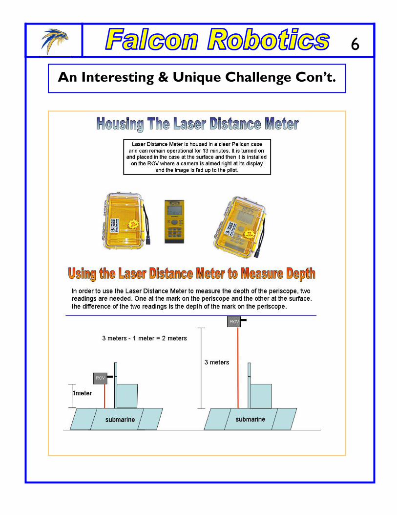
An Interesting & Unique Challenge Con’t.
6
Future Improvements
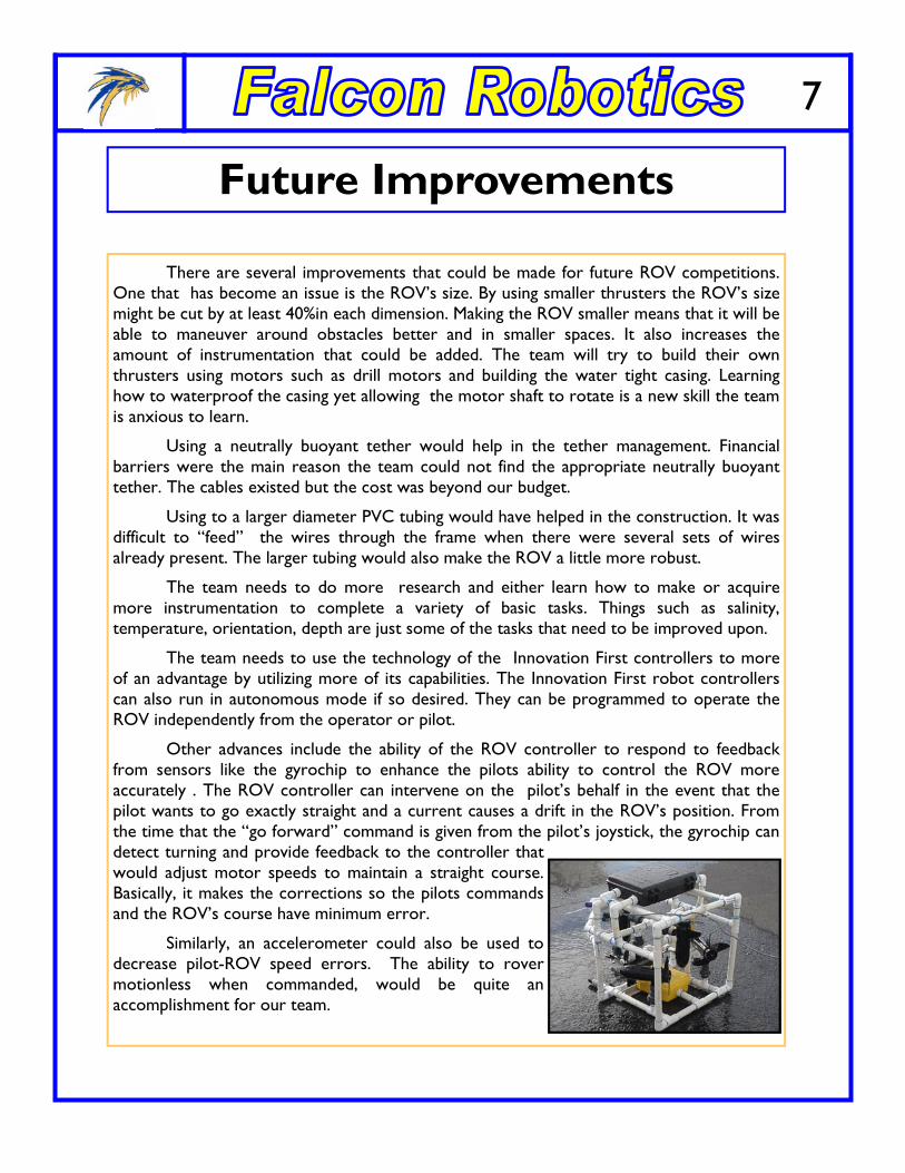
There are several improvements that could be made for future ROV competitions. One that has become an issue is the ROV’s size. By using smaller thrusters the ROV’s size might be cut by at least 40%in each dimension. Making the ROV smaller means that it will be able to maneuver around obstacles better and in smaller spaces. It also increases the amount of instrumentation that could be added. The team will try to build their own thrusters using motors such as drill motors and building the water tight casing. Learning how to waterproof the casing yet allowing the motor shaft to rotate is a new skill the team is anxious to learn.
Using a neutrally buoyant tether would help in the tether management. Financial barriers were the main reason the team could not find the appropriate neutrally buoyant tether. The cables existed but the cost was beyond our budget.
Using to a larger diameter PVC tubing would have helped in the construction. It was difficult to “feed” the wires through the frame when there were several sets of wires already present. The larger tubing would also make the ROV a little more robust.
The team needs to do more research and either learn how to make or acquire more instrumentation to complete a variety of basic tasks. Things such as salinity, temperature, orientation, depth are just some of the tasks that need to be improved upon.
The team needs to use the technology of the Innovation First controllers to more of an advantage by utilizing more of its capabilities. The Innovation First robot controllers can also run in autonomous mode if so desired. They can be programmed to operate the ROV independently from the operator or pilot.
Other advances include the ability of the ROV controller to respond to feedback from sensors like the gyrochip to enhance the pilots ability to control the ROV more accurately . The ROV controller can intervene on the pilot’s behalf in the event that the pilot wants to go exactly straight and a current causes a drift in the ROV’s position. From the time that the “go forward” command is given from the pilot’s joystick, the gyrochip can detect turning and provide feedback to the controller that would adjust motor speeds to maintain a straight course. Basically, it makes the corrections so the pilots commands and the ROV’s course have minimum error.
Similarly, an accelerometer could also be used to decrease pilot-ROV speed errors. The ability to rover motionless when commanded, would be quite an accomplishment for our team.
7

The control system has many safety features. The first one is inherent in the design of the control system. There are only low voltage, low current control lines going from the ROV to the pilot’s control panel. All high voltage, high current lines are on the ROV only and are isolated from the low voltage, low current control lines that go to the surface. On the ROV itself are many safety features. There is a 60amp breaker, that is also the on/off switch to protect the overall system. For each motor speed controller and 3 position relay there is a 20 amp auto reset circuit breaker that will trip permanently if continually stressed. The robot, or ROV, controller also has onboard fuses as well as the 3 position relays. The whole electronics package is encased in a plastic pelican case which is nonconductive. Having the wiring encased within the PVC pipe also reduces the chance of electri-cal shock due to the non-conductive PVC. By having the electronics in the Pelican case which is lo-cated at the top of the ROV, gives the control system a better chance for survival in the event of a leak in the ROV frame. Water will hopefully go to the lowest point in the frame and give the team time to “rescue” the ROV before the leak causes too much damage. One other safety feature is that if the control lines are disconnected from the pilot controller, all the motor speed controllers and relays as well as any other devices stop operating, rendering the ROV safer to handle. Only the ROV controller will receive power from the battery.
Electrical Schematics
All Onboard ROV
See
next
pag
e fo
r la
rger
sc
hem
atic
8

Electrical Schematics Con’t.
All Onboard ROV
9

Schematic for Control Box to Accommodate Four Joysticks into Two Joystick Ports
Electrical Schematics Con’t. Joystick 1
Joystick 2 Joystick 3 Joystick 4
Port 1
Port 2
Pilot Controller
10

Troubleshooting Techniques
The Innovation First control system comes with all sorts of indicators to assist with troubleshooting. The pilot controller has a voltage display that tell the pilot what the system or ROV’s voltage is. The control system cuts out at about 7-8 volts and the cameras cut out just below 9 volts, so if it appears the ROV is either loosing the pilot controller’s signal or the video is cutting out, then a quick check of the voltage display can help confirm this. There are other indicators that confirm if the motor speed controllers are activated as well as the relays. If the pilot feels that the left horizontal thruster is not responding then the pilot can check the display to see if the motor speed controller is responding. The pilot controller can also connect to a laptop computer that has a “Dashboard Viewer” program that has an extensive, customizable display where the pilot can read any of the display variables to make it easier to troubleshoot. The displays can also be used to operate the ROV in very specific conditions because the displays can show exact joystick positions. This can also help in programming the control system to have the joysticks operate under different operating curves. This feature is ideal to customize the controls to any pilot’s operating style.
12.3 v
Pilot Controller
Rov Controller
11

Troubleshooting Techniques, con’t.
There are, of course other methods of troubleshooting possible problems with the ROV. For example, if the robot controllers do not come on then there are two possibilities. Either the battery is dead or the system has not been turned on. This kind of systematic, logical process can help in tracking down the cause of problems. Here is another example. If the pilot controller display indicators show the devices as working, and in fact they are not, then checking the control lines from the ROV controller to the motor speed controller’s indicator is next. If the indicator works on the speed controller then checking the motor would follow. One of the chief problems typically is a loose connection. If the connections are not the problem then the fuses are the next possible culprit. One last possible method is to use a multi-meter to check all the connections and devices. It is a matter of following the path of operation to see where the problem could be. It is step by step process where we must eliminate each possible candidate one at a time until you find where the problem is.
Device indicators
12

13
Using ROVs to Explore and Understand our National Marine Sanctuaries
Using ROVs to Explore and Understand our National Marine Sanctuaries
There are four reasons why marine sanctuaries are using ROVs. First, ROVs are used to protect human lives. Secondly, they are also used to educate the public. Thirdly, they are used in deep submergence archeology. Lastly, they are perfect for various scientific studies. The functionality of the ROV allows one or several ROVs to perform all these aspects of research in a marine sanctuary.
Research in the marine environment can be dangerous. An example is a first hand account from Jeff Keitzmann who spoke with our ROV team. He explained that the leopard seals are deadly at the Palmer Station in Antarctica. A scientist was snorkeling to when he was attacked and killed by a leopard seal. He also said you have to check the water for them before entering. The very cold water is another danger to humans when conducting research. Because of this they do use ROVs as well. Currents and pack ice also endanger divers that enter the water there.
Another example of dangerous attacks is on Video Ray’s website. It describes an encounter that Steve Van Meter, a hazardous duty robotics specialist for NASA, had with an alligator. Steve was exploring the waters around NASA/Kennedy Space Center when a large alligator went tether to teeth with the 8lb ROV.
In order to promote global marine education instead of just the coastal states marine sanctuaries are starting to employ ROVs that can be remotely operated through the internet. One such ROV is Orpheus in the Monterey Bay National Marine Sanctuary in California. Orpheus is attached via a guide-wire between two pylons. It uses 2 thrusters to maneuver between them. According to a Popular Science March 2003 article, the Immersion Institute’s Robert Ballard is attempting a similar plan but aboard the wreck of the E.B. Allen which is just one of the 116 wrecks that can be found in the Thunder Bay Marine Sanctuary and Underwater Preserve in Lake Huron. The Institute is also planning on having these educational tools in the Channel Islands as well as Florida.

National Marine Sanctuaries Con’t.
14
National Marine Sanctuaries Con’t.
Much of the research that is happening in the Thunder Bay Marine Sanctuary in Lake Huron is deep submergence archeology. Most of the 116 shipwrecks in the sanctuary are not within sport diver range. The Immersion Institute that is doing the research uses an underwater ROV with the name of Little Hercules. This ROV has a color still camera, acoustic altimeter, sophisticated vehicle control, a scanning sonar as well as a lighting system. Scientists will use it in conjunction with a towed fiber optic vehicle, Argus, which has an array of visual and acoustic sensors. The ROV dives last approximately 4 hours but may run longer. The ship will conduct at least 2 launch and recoveries each day. During the dives the scientists will collect video and still images of the wrecks. The maximum depth of research is about 3000 m or 1.8 miles.
Lastly the scientific community is using ROVs for their precise capabilities. Sensors on the ROV allow for accurate collection of samples. There are autonomous ROVs being used for collection at the Palmer Station in Antarctica. Line transects are easily done using a video camera and ROV. Video Ray’s website quotes Larry Banbrick of the Discovery Channel Canada as saying, "When you're working in a hostile underwater environment like the high north, having the Video Ray act as a second pair of eyes is invaluable." They also claim that the Video Ray is non-invasive, and does not produce bubbles that scare fish. The scientists can set up a video camera on an ROV and leave it to watch the ecosystem or specific organism.

15
Skills Gained
The team worked together very well. Time and lack of experience with building robots that go underwater were the biggest obstacles for the team. Each member of the team has been on the Falcon Robotics team, and was familiar with working under stress and with different people on several robots and in several competitions. The group dynamics is clearly one of the team’s strengths. There are four seniors and three sophomores on the team. Leading the team there are three teacher sponsors with a variety of experiences.
One of the skills gained was that of making holes in cases and installing fittings while maintaining water tightness. This “lesson” was taught by a mentor to the team, Boris Innocenti, now retired and 80 years old. Borris ran a scuba shop in Phoenix, Arizona for thirty years and was well known for his expertise in building underwater housings for cameras and other electronic equipment. Boris was contacted by teacher mentor Fredi Lajvardi, who went to school with Boris's son. Boris had also been of assistance with the previous rov built by Fredi Lajvardi and the Science Seminar class. The team also gained skills in how O-rings work for water proofing the fittings from the trolling motors to the pvc pipes. Boris used his home garage machine shop to help the team make the custom fitted connections to the trolling motors. Also using electrical dust proof cord connectors to bring exposed cables into the PVC tubing. They are water proof too!
Case
2.54 cm diam fe-male slip pvc fitting with 1.25 cm male threaded end
O-ring being used as a gasket
Conduit nut
Steel trolling motor case
Case Fittings
PVC mate for trolling motors
O-rings
PVC fitting
Power lines
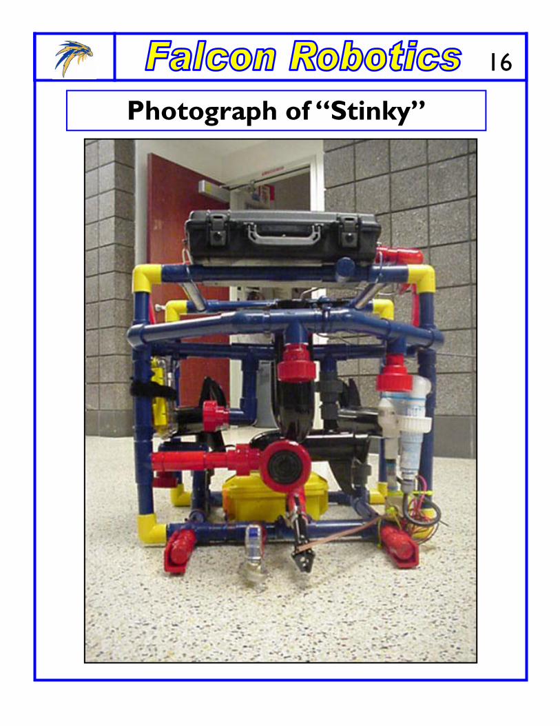
Photograph of “Stinky”
16

Photos of “Stinky” Con’t.
17
Open Pelican Case housing the control system and also acts as buoyancy.
Custom made fittings to bring electrical wires to the Pelican Case from pvc frame
Color CCD camera housed in 1/2 a pcv union. O-ring seal visible with lexan cover off.
Camera with cover on, as well as the two mi-crophones (red film canisters) and the claw.
Camera aimed at laser distance meter. Also rov battery in yellow Pelican case.
Rear view of rov with angled horizontal thrusters for greater steering.
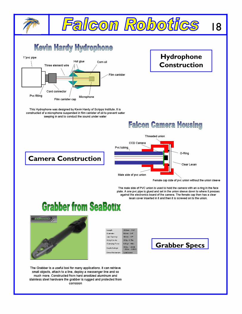
Hydrophone Construction
18
Camera Construction
Grabber Specs
Acknowledgements
• Boris Innocenti, retired scuba shop owner, Aqua Sports, Phoenix, Arizona For Menotoring the team in O-Ring technology and manufacturing fittings
• Greg De Tray, Distagage.com, [email protected] Lending the team two HD-150 Laser Distance Measuring Devices, & technical support
• Innovation FIRST inc., 6611 Interstate 30 west, Greenville, Texas, 75402 www.innovationfirst.com
For technical support on robot control system
• Donald Rodocker, President from Seabotix 1425 Russ Blvd, T112D, Sandiego, CA 92101, don @seabotix.com
For technical support and mentoring as well as lending a robotic arm or grabber for use on the rov. Also for tour of Seabotix facilities, Nov. 2003
• Kevin Hardy, Dir. For Centennial Special Program Development, Univ. Of California, San Diego– Scripps Institute of Oceanography, 9500 Gilman Dr. Lajolla, California 92093-0210
For technical information regarding micro cameras underwater and constructing hydrophones.
• Marine Advanced Technology Education Center, Monterey Peninsula College, 980 Freemont St. , Monterey, California, 93040
Summer workshop in 2003 for Dr. Allan Cameron and Fredi Lajvardi and for Travel Stipend for the National ROV Championships
• Phelps Dodge Corp., Honeywell, Intel, Wells Fargo, Microchip corp. and many individual sponsors for supporting the Carl Hayden High School, Science & Technology Club
• Frank Swankoski, Omega Engineering Inc. , Temperature Engineer [email protected]
For thermocouple wire and technical information
• Kevin Luebke, Mercury Marine, [email protected]
For a discounted price on trolling motors and technical support
• Walt Ahland, Lights Camera Action, 806 W. Impala Circle, Mesa, Arizona 85210-5996, [email protected]
For technical support and for locating and donating the rov tether
• Jeffrey S. Kietzmann, Plamer Station, Antarctica, Radio and Communications Specialist, expedition assistant and technical specialist. www.bedouinboundaries.com, [email protected]
For technical assistance and a visit to the school on May 24, 2004 to present slide show on the scientific work being done in Antarctica, including using ROV’s to collect temperature and salinity data.
19
20
Acknowledgements
Marine Sanctuary Report • http://thunderbay.noaa.gov/operations.html • http://www.mysticaquarium.org/latestdiscoveries/iferesearch/argus.asp • http://www.mysticaquarium.org/latestdiscoveries/iferesearch/dstd.asp • http://www.mysticaquarium.org/latestdiscoveries/iferesearch/orpheus.asp • http://www.videoray.com/Press_Room/steve.htm • http://www.videoray.com/Uses/science.htm • http://www.mysticaquarium.org/divein/immersion/immersion.asp • http://www.popsci.com/popsci/science/article/0%2C12543%2C429274%2C00.html • Jeffrey S. Kietzmann, Plamer Station, Antarctica, Radio and Communications Specialist,
expedition assistant and technical specialist. www.bedouinboundaries.com, [email protected]. Jeff offered technical assistance and visited our school on May 24, 2004. He presented slide the scientific work being done in Antarctica, including using ROV’s to collect temperature and salinity as well as biological data.