cartridge valves / in-line valves - brevini fluid power
TRANSCRIPT

®
CARTRIDGE VALVES / IN-LINE VALVES
Technical CatalogueJanuary
2019
web edition


i
IE/NDX/003/2016 TECHNICAL INFORMATION
Cartridge valves / In-line valves
Section index
Index and technical information ...................................................... i
Pressure relief valves ....................................................................... 1
Sequence, pressure reducing and unloading valves ...................... 2
Double cross relief valves ................................................................ 3
One-way check valves...................................................................... 4
Pilot check valves ............................................................................. 5
Manual and pneumatic operated valves ......................................... 6
End-off stroke valves........................................................................ 7
Solenoid valves 2-way ..................................................................... 8
Solenoid valves 3-4 way .................................................................. 9
Diverter valves ................................................................................. 10
Soft start valves ............................................................................... 11
Flow control valves .......................................................................... 12
Hand pumps ..................................................................................... 13
Valve housings ................................................................................. 14
Cavities............................................................................................. 15
Standard plugs ................................................................................. 16
Coils.................................................................................................. 17
Connectors ....................................................................................... 18
© 2018 Dana Brevini S.p.A. all rights reserved. Hydr-App, SAM Hydraulik, Aron, Brevini Hydraulics, BPE Electronics, VPS Brevini, OT Oiltechnology, logos are trademarks or are registered trademarks of Dana Brevini S.p.A. or other companies Dana in Italy and other countries.
The technical features supplied in this catalogue are non binding and no legal action can be taken against such material. Dana Brevini will not be held responsi-ble for information and specifications which may lead to error or incorrect interpretations. Given the continuous technical research aimed at improved technical features of our products, Dana Brevini reserves the right to make change that are considered appropriate without any prior notice. This catalogue cannot be reproduced (in while or in part) without the prior written consent of Dana Brevini. This catalogue supersedes all previous ones.
Use of the products in this catalogue must comply with the operating limits given in the technical specifications. The type of application and operating condi-tions must be assessed as normal or in malfunction in order to avoid endangering the safety of people and/or items..
®
1

i
IE/NDX/003/2016
CMP-HPV M14x1.5 5 14
CMP-MR/MW M15x1 6 15
CMP02 M16x1 20 16
CMP04 3/4-16UNF 30 17
CMPR04 (serie 2) 3/4-16UNF 30 18
CPMK04 3/4-16UNF 10 20
CMPR04 (serie 1) 3/4-16UNF 20 22
CMPHR04 3/4-16UNF 15 23
CPMC04 M18x1.5 30 24
CMP-MC/MS M18x1.5 20 25
CMP06 M20x1.5 30 26
CP06 7/8-14UNF 50 27
CMP20 M33x2 80 28
CMP30 M22x1.5 100 29
VMP02 1/4” BSP 30 30
VMP06 3/8” BSP 50 31
VMP10 3/8” BSP 40 32
T
P
T
P
T
P
T
P
U1
U
P
T
U1
U
P
T
T
P
T
P
T
P
T
P
T
P
P P
T
P
M
T
P
M
T
U1
U
P
T
U
P T1
T
T
P
TECHNICAL INFORMATION
Cartridge valves / In-line valves
DIRECT ACTING PRESSURE RELIEF VALVES (FOR HPV VALVES)
DIRECT ACTING PRESSURE RELIEF VALVES (FOR POWER PACKS SERIES MR/MW)
DIRECT ACTING PRESSURE RELIEF VALVES
DIRECT ACTING PRESSURE RELIEF VALVES
DIRECT ACTING PRESSURE RELIEF VALVES WITH ONE-WAY CHECK VALVE
DIRECT ACTING PRESSURE RELIEF VALVES WITH LOGIC VALVE
DIRECT ACTING PRESSURE RELIEF VALVES WITH ONE-WAY CHECK VALVE
DIRECT ACTING HIGH PRESSURE RELIEF VALVES WITH ONE-WAY CHECK VALVE
DIRECT ACTING PRESSURE RELIEF VALVES
DIRECT ACTING PRESSURE RELIEF VALVES (FOR POWER PACKS SERIES MC/MS)
DIRECT ACTING PRESSURE RELIEF VALVES
DIRECT ACTING PRESSURE RELIEF VALVES
DIRECT ACTING PRESSURE RELIEF VALVES
PILOT OPERATED PRESSURE RELIEF VALVES
DIRECT ACTING PRESSURE RELIEF VALVESIN-LINE MOUNTING
DIRECT ACTING PRESSURE RELIEF VALVESIN-LINE MOUNTING
DIRECT ACTING PRESSURE RELIEF VALVESIN-LINE MOUNTING
1 PRESSURE RELIEF VALVES (PAGE 13)
Code Thread Flow (l/min) Symbol Description Page
®
2

i
IE/NDX/003/2016
2
1
P(in) P(out)
T
Y
PRPP
T
Y
PRPP
T
Y
PR
T P
M
PR T
P
M
A
A1
B
B1
CSQ04 3/4-16UNF 30 38
CSMK04 3/4-16UNF 10 39
CVS20 M22x1.5 90 40
CVR06 7/8-14UNF 20 41
CVR20 M22x1.5 150 42
CVE06 7/8-14UNF 30 43
CRC1 1/2” BSP 90 44
VADIL BSP: 1/4” - 3/8” 30 46
1 3
2
3 2
1 1
32A B
VMP20 1/2” BSP 80 33
VMP30 3/4” BSP 100 34
VMP12 BSP: 3/4” - 1” 150 35
P P
T
P
M
T
P
M
T
TECHNICAL INFORMATION
Cartridge valves / In-line valves
2 SEQUENCE, PRESSURE REDUCING AND UNLOADING VALVES (PAGE 37)
3 DOUBLE CROSS RELIEF VALVES (PAGE 45)
Code Thread Flow (l/min) Symbol Description Page
Code Thread Flow (l/min) Symbol Description Page
SEQUENCE VALVES - DIRECTLY OPERATED
SEQUENCE VALVES - DIRECTLY OPERATED(FOR MK3 SERIES POWER PACKS)
SEQUENCE VALVES - PILOT OPERATED
PRESSURE REDUCING VALVES WITH RELIEVING - DIRECT OPERATED
PRESSURE REDUCING VALVES WITH RELIEVING - PILOT OPERATED
SEQUENCE VALVES
PRESSURE REDUCING AND SEQUENCE VALVESIN-LINE MOUNTING
DOUBLE CROSS RELIEF VALVES DIRECT ACTINGIN-LINE MOUNTING
1 PRESSURE RELIEF VALVES (PAGE 13)
VALVOLE DI MASSIMA PRESSIONE AD AZIONE DIRETTAMONTAGGIO IN LINEA
VALVOLE DI MASSIMA PRESSIONE AD AZIONE PILOTATA MONTAGGIO IN LINEA
VALVOLE DI MASSIMA PRESSIONE AD AZIONE PILOTATAMONTAGGIO IN LINEA
Code Thread Flow (l/min) Symbol Description Page
®
3

i
IE/NDX/003/2016
12
X
12
12
X
12
12
12
U1
U
P
T
12
12
AA1
A A1
1
2
3
1
2
3
1
2
X
3
2
1
CRU-MR M15x1 10 48
CRU-MC/MS M16x1.5 20 49
CRU04 3/4-16UNF 40 50
CRU06 7/8-14UNF 60 51
CRI04 3/4-16UNF 20 52
VR06 3/8” BSP 30 53
VUI BSP: 1/4” - 3/8” - 1/2” 20 - 50 - 80 54
VRUBSP: 1/4” - 3/8”
1/2” - 3/4 - 1” 1” 1/4 - 1” 1/2
20 - 35 - 50 80 - 140
200 - 31055
VUBA BSP: 1/4” - 3/8” 1/2” - 3/4
4 - 6.3 16 - 25 56
SH01 M8x1 2 58
SH02 1/8” BSP 8 59
SH03 1/4” BSP 5 60
RVLV0 M16x1.5 7 61
RVLV1 M27x1.5 140 62
1
2
3
TECHNICAL INFORMATION
Cartridge valves / In-line valves4 ONE-WAY CHECK VALVES (PAGE 47)
Code Thread Flow (l/min) Symbol Description Page
ONE-WAY CHECK VALVES
ONE-WAY CHECK VALVES
ONE-WAY CHECK VALVES
ONE-WAY CHECK VALVES
ONE-WAY CHECK VALVES (FOR POWER PACKS SERIES FP)
ONE-WAY CHECK VALVES
ONE-WAY CHECK VALVES
ONE-WAY CHECK VALVESIN-LINE MOUNTING
CHECK VALVES FOR PIPES
SHUTTLE VALVES
SHUTTLE VALVES
SHUTTLE VALVES
SHUTTLE VALVES
PUMP UNLOADING VALVES
®
4

i
IE/NDX/003/2016
A
X
A1
A1
A
B1
B
A1
A
B1
B
A1
A
B1
B
A1
A
B1
B
VRS1/4” BSP
BSP: 1/4”-3/8”-1/2”-3/4”
12 - 3045 - 85 64
VBPSA-VBPDABSP: 1/4” - 3/8”
1/2” - 3/4” 9/16-18 UNF
20 - 25 45 - 85 65
VBPSA-VBPDA DIN BSP: 1/4” - 3/8” 20 - 25 67
CMF04 3/4-16UNF 15 70
CPE04 3/4-16UNF 30 71
CRD04P 3/4-16UNF 30 72
VFC 3/8” BSP 40 74
VD40 1/2” BSP 40 75
2
1
2
1
2
1
2
1
X
B
A
P
Y
A
TECHNICAL INFORMATION
5 PILOT CHECK VALVES (PAGE 63)
Code Thread Flow (l/min) Symbol Description Page
SINGLE ACTING PILOTED CHECK VALVES
SINGLE AND DOUBLE ACTING PILOT CHECK VALVES
SINGLE AND DOUBLE ACTING PILOT CHECK VALVES-DIN 2353 PORTS
Cartridge valves / In-line valves
6 MANUAL AND PNEUMATIC OPERATED VALVES (PAGE 69)
7 END-OFF STROKE VALVES (PAGE 73)
LEVER OPERATED VALVES
BUTTON OPERATED VALVES
PNEUMATIC OPERATED VALVES
END-OFF STROKE VALVESIN-LINE MOUNTING
DECELERATION VALVESIN-LINE MOUNTING
Code Thread Flow (l/min) Symbol Description Page
Code Thread Flow (l/min) Symbol Description Page
®
5

i
IE/NDX/003/2016
CRB04 3/4-16UNF 40 78
CRP04 3/4-16UNF 40 78
CRP04HP 3/4-16UNF 30 80
CRP04X 3/4-16UNF 20 82
CRD04 3/4-16UNF 15 - 30 84
C2V04 3/4-16UNF 15 86
1
2 2
1
1
2
1
2
1
2
1
2
1
2
1
2
1
2
1
2 2
1
1 3
2
1 3
2
13
2 4
13
2 4
13
2 4
13
2 4
13
2 4
1 3
2
C3V0422 3/4-16UNF 12 88
C3V0427 3/4-16UNF 20 89
C3V03 7/8-14UNF 20 90
C4V0422*2 3/4-16UNF 18 91
C4V0422*3 3/4-16UNF 18 92
1 3
2
13S2 S1
2 4
S2 S113
2 4
S2 S113
2 4
S2 S113
2 4
TECHNICAL INFORMATION
Cartridge valves / In-line valves8 SOLENOID VALVES 2-WAY (PAGE 77)
PILOTED OPERATED CARTRIDGE SOLENOID VALVE BIDIRECTIONAL
PILOTED OPERATED CARTRIDGE SOLENOID VALVE UNIDIRECTIONAL
HIGH PRESSURE PILOTED OPERATED CARTRIDGE SOLENOID VALVE
VALVES IN ACCORDANCE WITH ATEX 94/9/CE DIRECTIVE
DIRECT OPERATED CARTRIDGE SOLENOID VALVE
CARTRIDGE SOLENOID VALVES 2 WAY 2 POSITIONS
Code Thread Flow (l/min) Symbol Description Page
Code Thread Flow (l/min) Symbol Description Page
9 SOLENOID VALVES 3-4 WAY (PAGE 87)
SOLENOID VALVES 3-WAY/2-POSITION
SOLENOID VALVES 3-WAY/2-POSITION
SOLENOID VALVES 3 WAY 2 POSITIONS
SOLENOID VALVES 4 WAY 2 POSITIONS
SOLENOID VALVES 4 WAY 3 POSITIONS
®
6

i
IE/NDX/003/2016
1 2
A B
P
AB
P
1 2
A B
P
AB
P
P
BA
1 2 P
BA
1 2
P
T
P
T
0.4
0.2-0.5 bar
MR 1/4” BSP1/4”BSPT — 94
RBSBSP: 1/8” - 1/4” 3/8”- 1/2” - 3/4” 1” - 1”1/4 - 1”1/2
5 - 10 - 25 40 - 100 - 150 95
BK3BSP: 1/8” - 1/4”
3/8” - 1/2” - 3/4” 1” - 1”1/4 - 1”1/2
5 - 10 - 25 70 - 100 - 150 96
DDF BSP: 1/4” - 3/8” 1/2” - 3/4 - 1”
60 - 90120 - 200 97
VAM04 1/4” BSP 20 100
VAMS04 1/4” BSP 8 101
TECHNICAL INFORMATION
Cartridge valves / In-line valves
Code Thread Flow (l/min) Symbol Description Page
Code Thread Flow (l/min) Symbol Description Page
11 DIVERTER VALVES (PAGE 93)
12 SOFT START VALVES (PAGE 99)
PRESSURE GAUGE SHUT-OFFIN-LINE MOUNTING
HIGH PRESSURE - 2 WAY BALL VALVESIN-LINE MOUNTING
HIGH PRESSURE - 3 WAY BALL VALVESIN-LINE MOUNTING
DIVERTER VALVESIN-LINE MOUNTING
SINGLE-PHASE MOTOR START VALVEIN-LINE MOUNTING
SOFT START VALVEIN-LINE MOUNTING
®
7

i
IE/NDX/003/2016
1 212
1 2
21
1 2
1 2
31
2
PI PU
X
PI PU
X
A A1A A1
A A1A A1
A A1
2
1
SU/SB M10x1 15 104
VSU 1/4” BSP 20 105
CSB04 3/4-16UNF 40 106
CSC04 3/4-16UNF 29 107
VSC04 1/4” BSP 11,7 108
VSC06 3/8” BSP 18,5 109
CRF06 7/8-14UNF 50 110
CCI06 7/8-14UNF 80 111
CCP20 M22x1.5 50 112
VSR/VSB BSP: 1/4” - 3/8” 1/2” - 3/4” - 1”
15 - 30 45 - 85 - 100 113
STU/STB BSP: 1/4” - 3/8” 1/2” - 3/4” - 1”
20 - 30 50 - 85 - 150 114
STC 3/8” BSP 29 115
CPM04 3/4-16UNF 1cc - 2cc 118
12
2
3
1
TECHNICAL INFORMATION
Cartridge valves / In-line valves
Code Thread Flow (l/min) Symbol Description Page
Code Thread Flow (l/min) Symbol Description Page
13 FLOW CONTROL VALVES (PAGE 103)
14 HAND PUMPS (PAGE 117)
UNIDIRECTIONAL AND BIDIRECTIONAL FLOW REGULATOR VALVES
FIXED UNIDIRECTIONAL FLOW CONTROL VALVE
BIDIRECTIONAL NOT COMPENSATED FLOW CONTROL VALVE
UNIDIRECTIONAL COMPENSATED FLOW CONTROL VALVE
FIXED PRESSURE COMPENSATED FLOW CONTROL VALVE
PRESSURE COMPENSATED FLOW CONTROL VALVES
PRIORITARY FLOW CONTROL VALVE
PRESSURE COMPENSATOR VALVE
TWO-WAY PRESSURE COMPENSATOR VALVE
SLEEVE FLOW CONTROL VALVES UNIDIRECTIONAL AND BIDIRECTIONAL - IN-LINE MOUNTING
UNIDIRECTIONAL AND BIDIRECTIONAL FLOW REGULATOR VALVES - IN-LINE MOUNTING
PRESSURE COMPENSATED FLOW UNIDIRECTIONAL FLOW REGULATOR VALVES - IN-LINE MOUNTING
HAND PUMP
®
8

i
IE/NDX/003/2016
BK3 .......................................................................... 96C2V04 ...................................................................... 86C3V03 ...................................................................... 90C3V0422 .................................................................. 88C3V0427 .................................................................. 89C4V0422*2 .............................................................. 91C4V0422*3 .............................................................. 92CCI06 ...................................................................... 111CCP20 .....................................................................112CMF04 ..................................................................... 70CMP02 ..................................................................... 16CMP04 ..................................................................... 17CMP06 ..................................................................... 26CMP20 ..................................................................... 28CMP30 ..................................................................... 29CMP-HPV ................................................................. 14CMPHR04 ................................................................ 23CMP-MC/MS ........................................................... 25CMP-MR/MW .......................................................... 15CMPR04 (serie 1) .................................................... 22CMPR04 (serie 2) .................................................... 18CP06 ........................................................................ 27CPE04 ...................................................................... 71CPM04 ....................................................................118CPMC04 .................................................................. 24CPMK04 .................................................................. 20CRB04 / CRP04 ....................................................... 78CRC1 ....................................................................... 44CRD04 ..................................................................... 84CRD04P ................................................................... 72CRF06 .....................................................................110CRI04 ....................................................................... 52CRP04HP ................................................................. 80CRP04X ................................................................... 82CRU04 ..................................................................... 50CRU06 ..................................................................... 51CRU-MC/MS ............................................................ 49CRU-MR .................................................................. 48CSB04 .................................................................... 106CSC04 .................................................................... 107CSMK04 .................................................................. 39CSQ04 ..................................................................... 38CVE06 ...................................................................... 43CVR06 ...................................................................... 41CVR20 ...................................................................... 42CVS20 ...................................................................... 40
DDF ......................................................................... 97MR ........................................................................... 94RBS .......................................................................... 95RVLV0 ...................................................................... 61RVLV1 ...................................................................... 62SH01 ........................................................................ 58SH02 ........................................................................ 59SH03 ........................................................................ 60STC .........................................................................115STU/STB .................................................................114SU/SB .................................................................... 104VADIL ....................................................................... 46VAM04 ................................................................... 100VAMS04 ..................................................................101VBPSA-VBPDA ......................................................... 65VBPSA-VBPDA DIN ................................................. 67VD40 ........................................................................ 75VFC ...........................................................................74VMP02 ..................................................................... 30VMP06 ..................................................................... 31VMP10 ..................................................................... 32VMP12 ..................................................................... 35VMP20 ..................................................................... 33VMP30 ..................................................................... 34VR06 ........................................................................ 53VRS .......................................................................... 64VRU ......................................................................... 55VSC04 .................................................................... 108VSC06 .................................................................... 109VSR/VSB .................................................................113VSU ........................................................................ 105VUBA ....................................................................... 56VUI ........................................................................... 54
TECHNICAL INFORMATION
VALVE PAGE VALVE PAGE
Cartridge valves / In-line valves
Section index ............................................................. 1Technical information ............................................... 10Valve housings ....................................................... 120Cavities .................................................................. 124Standard plugs ....................................................... 132Coils ....................................................................... 136Connectors ............................................................ 142
®
9

i
IE/NDX/003/2016
min. max.
ISO VG 10 10 9.00 11.0
ISO VG 15 15 13.5 16.5
ISO VG 22 22 19.8 24.2
ISO VG 32 32 28.8 35.2
ISO VG 46 46 41.4 50.6
ISO VG 68 68 61.2 74.8
ISO VG 100 100 90.0 110
15000
600
4000400
2000
5000
200
1000
1500
100
400
500
40
200
300
20
50
1505 30
50
SSU °E mm²/s
310
20000500
5000
10000 300 3000
2000
150
1500
1000
50
500
400
30
300
200
10
100
100
4
40
2
20
0 1 0
mm²/s°E
°C
°F
ISO
VG
100
ISO
VG
68
ISO
VG
32
ISO
VG
22
ISO
VG
46
-20
2.80
3
3.5
4
4.5
5
6
7
8
9
10
12
11
13
15
17
20
25
30
40
50
60
70
100
150
200
300
400
600
800
1000
1500
2000
3000
5000
7000
10000
2000
1000
500
300
200
100
70
40
20
10
8
6
4
3
2
1.8
1.6
1.4
1.3
1.2
-5-15 0-10 5 10 15 20 40 60 9025 30 50 8070 100
210140 200130100700
110
TECHNICAL INFORMATION
Technical information
Read this instructions carefully before installation. All operations must be carried out by qualified personnel following the instructions.
The user must periodically inspect, based on the conditions of use and the substances used, the presence of corrosion, dirt, the state of wear and correct function of the valves.
Always observe first the operating conditions given in datasheet of the valve.
INTRODUCTION
VISCOSITY
Observe the recommendations given in the data sheet of the valve.The oil viscosity must be in the range of 10 mm²/s to 500 mm²/s.Recommended oil viscosity 46 mm2/s (32 mm2/s for Cartridge valves)
Table 1: ISO viscosity grades
Kinematic-viscosity limits
mm²/s @ 40°C
Averagekinematicviscosity
mm²/s @ 40°C
Viscositygrade
= Values used in the chart “Oil viscosity according to temperature”
OIL VISCOSITY ACCORDING TO TEMPERATURE
CONVERSION TABLE SSU / °E / mm²/s
HYDRAULIC FLUID
Observe the recommendations given in the data sheet of the valve. Use only mineral oil (HL, HLP) according to DIN 51524. Use of other different fluids may damage the good operation of the valve.
CONTAMINATION
Oil contamination is the main cause of faults and malfunction in hydraulic systems. Abrasive particles in the fluid erode or block moving parts, leading to system malfunction.The valves we are offering do not require filtering characteristics any higher than those needed for usual hydraulic components such as pumps, motors, etc.
However, accurate filtering does guarantee reliability and a long life to all the system’s hydraulic parts. Reliable performance and long working life for all oil-pressure parts is assured by maintaining the level of fluid contamination within the limits specified in the data sheet of the valve.
Hydraulic fluid must also be cleaned properly before filling the hydraulic cir-cuit, especially when commissioning a new system, as this is when the oil contamination generally peaks due to its flushing effect on the components, and the running-in of the pump.Maximum contamination level is required on datasheet of the valve accord-ing to ISO 4406:1999.
In the following table there is the correspondence between ISO 4406:1999 and old standard NAS 1638 for information purpose:The standard ISO 4406:1999 defines the contamination level with three num-bers that relate with the number of particles of average dimension equal or greater than 4 μm, 6 μm e 14 μm, in 1 ml of fliuid.
In following table there is a reference to reccomended contamination level and correspondence with old NAS 1638 standard.
®
10

i
IE/NDX/003/2016 TECHNICAL INFORMATION
Type of systemType of valve
Oil filtration recommendationsCleanliness class
recommendedAbsolute filtration
micron rating ( ** )
ISO 4406 : 1999 NAS 1638 ( * )
Systems or components operating at HIGH PRESSURE > 250 bar (3600 psi)HIGH DUTY CYCLE APPLICATIONSSystems or components with LOW dirt tolerance
18 / 16 / 13 7 - 8 5
Systems or components operating at MEDIUM / HIGH PRESSURESystems and components with moderate dirt tolerance
19 / 17 / 14 9 10
Systems or components operating at LOW PRESSURE < 100 bar (1500 psi)LOW DUTY CYCLE APPLICATIONSSystems and components with GOOD dirt tolerance
20 / 18 / 15 10 - 11 20
Technical information
Type SI units Alternative units Conversion factor
Force Newton (N) [kgm/s²]Kilogram force (kgf) 1 kgf = 9.807 Npound force (lbf) [lbf/s²] 1 lgf = 4.448 N
Lengthmillimeter (mm) [10 m] inch (in) 1 in = 25.4 mmmeter (km) [1000 m] yard (yd) [3ft] 1 m = 1.0936 ydkilometer (km) [1000 m] mile (mile) [1760 yd] 1 mile = 1.609 km
Torque Newton meter (Nm) pound force.feet (lbf.ft) 1 lbf.ft = 1.356 Nm
Power kiloWatt (kW) [1000 Nm/s]horsepower (hp) 1 kW = 1.341 hpmetric horsepower (CV) 1 kW = 1.36 CV
Pressure MegaPascal (MPa) [ N/mm²]bar 1 MPa = 10 barpsi (lbf/ln²) 1 MPa = 145 psiton/f/ln² 1 ton/f/ln² = 15.45 MPa
Flow rate liter/min (l/min)UK gal/min 1 UK gal/min = 4.546 l/minUS gal/min 1 US gal/min = 3.785 l/min
Temperature Degrees Celsius (°C) Farenheit (°F) 1°F = 1.8 °C+32
Ambient temperature range: -25°C to +60°CFluid temperature range (NBR seals): -25°C to +75°CThermal shocks can affect the performance and the expected life of the prod-uct, hence it is necessary to protect the product from these conditions.
WORKING TEMPERATURES
SEALS
O-rings made in Acrylonitrile Butadiene (NBR) are normally fitted on the valves. The backup rings that protect the O-rings are also made in NBR, or sometimes PTFE. Both the O-rings and the backup rings are suitable for the working temperatures mentioned above.In the case of fluid temperatures > 75°C, FKM seals must be used (identified with “V1” variant).
CONVERSION CHART
* Contamination class NAS 1638: it is determined by counting the total particles of different size ranges contained in 100 ml of fluid.
** Absolute filtration: it is a characteristic of each filter, it refers the size (in micron) of the largest sperical particle wich may pass through the filter.
Table 2: Reccomanded contamination level.
Solenoid valves coils are designed to operate safely in the voltage range of ±10% of nominal voltage at max. 60°C ambient temperature. The combination of permanent overvoltage and very hot temperatures can stress the solenoid. Therefore always a good heat dissipation and voltage level has to be assured.Faulty coils may only be replaced by new, interchangeable, tested compo-
ELECTRICAL POWER SUPPLY
The mounting surface must feature surface quality specified in data sheet of the valve: for example for Cetop valves generally is required Ra 1.6μm and flatness 0.03 mm over 100 mm length. Normally in cartridge valve for sea-ling diameters of the cavities, is required roughness Ra 1.6μm. The surfaces and openings in the assembly plate must be free from impurity or dirt.Make sure the O-Rings fit correctly in their seats.Fixing screws must comply with the dimensions and the strength class spe-cified in the data sheet and must be tightened at the specified tightening torque.Complete the electrical wiring. For circuit examples and pin assignments, see the relevant datasheet.
INSTALLATION
nents in original-equipment quality.Before removing a coil, voltage must be disconnected.When replacing the coil, be aware to insert O-Rings in order to avoid the entrance of water.
Observe the functional limits indicated in the technical catalogueOn a periodic basis and based on the conditions of use, check for cleanliness, state of wear or fractures and correct performance of the valve.If the O-rings are damaged, replace them with those supplied by the manu-facturer.To assure the best working conditions at all time, check the oiland replace it periodically (after the first 100 working hours and then after every 2000 working hours or at least once every year).Attention: all installation and maintenance intervention must be performed by qualified staff.
USE AND MAINTENANCE
TRANSPORT AND STORAGE
The valve must be handled with care to avoid damage caused by impact, which could compromise its efficiency.In the case of storage, keep the valves in a dry place and protect against dust and corrosive substances.When storing for periods of more than 6 months, fill the valve with preserving oils and seal it.
®
11

i
IE/NDX/003/2016TECHNICAL INFORMATION
®
12

1
IE/C1/001/2011 PRESSURE RELIEF VALVES
PRESSURE RELIEF VALVES
®
13

1
CMP-HPV
T
P
0 1 2 3 4 5
0
50
100
150
200
250
300
350
400
Q (l/min)
P(b
ar)
0 1 2 3 4 5
0
5
10
15
20
25
30
35
40
45
50
Q (l/min)
P(b
ar)
39
Ø17
21.8 max
M10x1
M14x1.5
5÷6 Nmmax 5 Nm16÷18 Nm
10
6
7
3
P
T
IE/CMP-HPV/001/2011PRESSURE RELIEF VALVES
DIRECT ACTING PRESSURE RELIEF VALVES (FOR HPV VALVES)
HYDRAULIC FEATURES
HYDRAULIC SYMBOL
Max. working pressure 400 bar
Max. Flow 5 l/min
Hydraulic fluid DIN 51524 Mineral oils
Fluid viscosity 10 ÷ 500 mm2/s
Fluid temperature -25°C ÷ 75°C
Ambient temperature -25°C ÷ 60°C
Max. contamin. level class with filter ISO 4406:1999 - class 19/17/14
Weight 0.038 kg
Tightening torque see draw
Cavity (M14x1.5) CN032005 (See section 17)
ORDERING CODE
Code Description
RKVL1130002 Direct acting relief valve
Fluid used: mineral based oil with viscosity 46 mm²/s at 40°C.
MIN.SETTING PRESSUREPRESSURE-FLOW RATE
The direct acting relief valve limits the pressure in a hydraulic circuit to within the specified calibration range.It has a galvanised steel body. The tapered poppet is in tempered steel.
00012001 Spare seals kit
®
14

1
CMP-MR/MW
T
P
IE/CMP_MR-MW/001/2011
Q (l/min)
P(b
ar)
0
15
30
45
60
75
90
0 1 2 3 4 5 6
Q (l/min)
P(b
ar)
0
50
100
150
200
250
300
0 1 2 3 4 5 6
Q (l/min)
P(b
ar)
0
6
12
18
24
30
36
0 1 2 3 4 5 6
25 ÷ 80 bar 75 ÷ 220 bar 5 ÷ 30 bar
1934 max
Ø12
M15
x1
1
16÷19 Nm
10 17
14
3
AP
T
max 5 Nm
PRESSURE RELIEF VALVES
DIRECT ACTING PRESSURE RELIEF VALVES (FOR POWER PACKS SERIES MR/MW)
HYDRAULIC FEATURES
PRESSURE-FLOW RATE
HYDRAULIC SYMBOL
Fluid used: mineral based oil with viscosity 32 mm²/s at 50°C.
Max. working pressure 220 barSetting range:Spring ASpring CSpring C
25 ÷ 80 bar75 ÷ 220 bar5 ÷ 30 bar
Max. Flow 6 l/min
Hydraulic fluid DIN 51524 Mineral oils
Fluid viscosity 10 ÷ 500 mm2/s
Fluid temperature -25°C ÷ 75°C
Ambient temperature -25°C ÷ 60°C
Max. contamin. level class with filter ISO 4406:1999 - class 19/17/14
Weight 0.05 kg
Tightening torque see draw
Cavity (M15x1) CN033001 (See section 17)The minimum permissible setting pressure depending on the spring: see curves below
ORDERING CODE
Code Identification (see draw)
Setting range
Pressure increasing at each turn of screw
21000010.000 A 25 ÷ 80 bar 17 bar ± 10%
21000011.000 B 75 ÷ 220 bar 45 bar ± 10%
21000009.000 C 5 ÷ 30 bar 7 bar ± 10%
Pressureidentification
The direct acting relief valve limits the pressure in a hydraulic circuit.It raises the safety level by making it impossible for the plant operators to set a higher pressure rating, than that specified in the catalogue. It has a pack spring with a mechanical stop. It has a galvanised steel body. The guided ball poppet is in tempered and ground steel.
00012002 Spare seals kit
®
15

1
CMP02
1 = CMP02C1.. - 2 = CMP02C2.. - 3 = CMP02C3.. - 4 = CMP02C4..
T
P
CMP 02 * * ** 1
1
2
3
4
Q (l/min)
P(b
ar)
0
20
220
120
40
240
140
60
260
160
80
280
180
100
200
0 2 4 6 8 10 12 14 16 18 20
4
1
2
3
Q (l/min)
P(b
ar)
0
10
20
30
40
50
60
70
80
90
100
0 2 4 6 8 10 12 14 16 18 20
M1
6 x
1
Ø 3
4.5
M1
0 x
1
Ø6
.6
5
10
19
Ø 2
2
49.5 max
48.5 max
30.8
14.8
13÷18 Nm 5÷6 Nm
P
T
M
C
max 5 Nm
IE/CMP02/002/2012PRESSURE RELIEF VALVES
DIRECT ACTING PRESSURE RELIEF VALVES
The direct acting relief valve limits the pressure in a hydraulic circuit.It raises the safety level by making it impossible for the plant operators to set a higher pressure rating, than that specified in the catalogue. This is limited by a pack spring with a mechanical stop (only standard screw and nut), which prevents temporary P closures caused by pressure peaks.It has a galvanised steel body. The guided ball poppet is in tempered and ground steel.
HYDRAULIC FEATURES
PRESSURE-FLOW RATE
HYDRAULIC SYMBOL
Fluid used: mineral based oil with viscosity 46 mm²/s at 40°C.
CMP = Pressure relief valve
02 = M16 x 1
ORDERING CODE
1 = Serial No.
00 = No variantsV1 = Viton
1 = Max 30 bar (white spring)2 = Max 90 bar (yellow spring)3 = Max 180 bar (green spring)4 = Max 250 bar (orange spring)
Series
Size
Settingranges
Max. working pressure 250 barSetting range:Spring 1 (white)Spring 2 (yellow)Spring 3 (green)Spring 4 (orange)
max 30 barmax 90 barmax 180 barmax 250 bar
Max. Flow 20 l/min
Hydraulic fluid DIN 51524 Mineral oils
Fluid viscosity 10 ÷ 500 mm2/s
Fluid temperature -25°C ÷ 75°C
Ambient temperature -25°C ÷ 60°C
Max. contamin. level class with filter ISO 4406:1999 - class 19/17/14
Weight 0.1 kg
Tightening torque see draw
Cavity (M16x1) CN036001 (See section 17)
Adjustment
MIN.SETTING PRESSUREThe minimum permissible setting pressure depending on the spring: see curves below
Variants
Q25830021 O-ring spare part
C = ScrewM = Plastic knob
®
16

1
CMP04
0 = CMP04*0 - 1 = CMP04*1.. - 2 = CMP04*2.. - 3 = CMP04*3..T
P
IE/CMP04/003/2016
New!
Tipo di sede
CMP 04 * * * 00 2
Ø 1
2.7
Ø 1
5.8
7
Q (l/min)
P(b
ar)
0
50
200
250
300
100
350
150
0 5 10 15 20 25 30
0
1
2
3
3
2
1
0
Q (l/min)
P(b
ar)
0
10
15
5
20
25
30
35
40
45
50
55
70
60
65
0 5 10 15 20 25 30
Ø 7
.2
Ø 1
2.7
3/4
-16 U
NF
52.3 30
82.3
25.9
Ø 2
2
36.5
T
P
Ø 2
6
55.25
T
P
Ø 3
5
63
T
P
3
3
24
2
10
S
M
C
max 5 Nm
25÷30 Nm
max 0.5 Nm
Ø 2
6
55.25
T
PP
PRESSURE RELIEF VALVES
DIRECT ACTING PRESSURE RELIEF VALVES
HYDRAULIC FEATURES
PRESSURE-FLOW RATE
HYDRAULIC SYMBOL
Fluid used: mineral based oil with viscosity 46 mm²/s at 40°C.
CMP = Pressure relief valve
ORDERING CODE
2 = Serial No.
00 = No variants
Series
Size
Settingranges
Max. working pressure 350 barSetting range:Spring 0 (white)Spring 1 (green)Spring 2 (yellow)Spring 3 (red)
max 50 barmax 110 barmax 220 barmax 350 bar
Max. Flow 30 l/min
Hydraulic fluid DIN 51524 Mineral oils
Fluid viscosity 10 ÷ 500 mm2/s
Fluid temperature -25°C ÷ 75°C
Ambient temperature -25°C ÷ 60°C
Max. contamin. level class with filter ISO 4406:1999 - class 19/17/14
Weight 0.15 kg
Tightening torque 25 ÷ 30 Nm
Cavity (3/4 - 16 UNF) CD018006 (See section 17)
0 = Max 50 bar (white spring) 1 = Max 110 bar (green spring)2 = Max 220 bar (yellow spring)3 = Max 350 bar (red spring)
AdjustmentC = Screw P = C + Plug no detachable closing (unremovable version)S = C + Plug detachable closingM = Plastic knob
04 = 3/4 - 16 UNF
MIN.SETTING PRESSURE
The minimum permissible setting pressure depending on the spring: see curves below
Variants
The direct acting relief valve limits the pressure in a hydraulic circuit.It raises the safety level by making it impossible for the plant operators to set a higher pressure rating, than that specified in the catalogue. It has a pack spring with a mechanical stop. It has a galvanised steel body. The guided ball poppet is in tempered and ground steel.
00012036 Spare seals kit
Reduction for cavity type “B”
V89B30000 Spare code
Seat sizeA = Standard - Ø 12.7 mmB = With reduction - Ø 15.9 mm
®
17

1
New!CMPR04 (serie 2)
U1
U
P
T
IE/CMPR-2/000/2016
3/4
- 1
6 U
NF
50.3
Ø 2
2
Ø 1
4.5
Ø 1
5.867.5
117.8
34.5
25÷30 Nm
T P U1
U
Ø 2
6
53.25
T P
U
U1
61.0
Ø 3
5
T P
U
U1
2
3
10 24
M
S
C
max 5 Nm
2
max 0.5 Nm
Ø 2
6
53.25
T P
U
U1
P
PRESSURE RELIEF VALVES
DIRECT ACTING PRESSURE RELIEF VALVES WITH ONE-WAY CHECK VALVE
HYDRAULIC FEATURES
Max. working pressure 350 bar
Max. Flow 30 l/min
Setting range:Spring 0 (white)Spring 1 (green)Spring 2 (yellow)Spring 3 (red)
max 50 barmax 110 barmax 220 barmax 350 bar
One-way check valve 0,5 bar (standard)
Check valve leakage (0 ÷ 5 drops/min) 0 ÷ 0.25 cm3/min
Hydraulic fluid DIN 51524 Mineral oils
Fluid viscosity 10 ÷ 500 mm2/s
Fluid temperature -25°C ÷ 75°C
Ambient temperature -25°C ÷ 60°C
Max. contamin. level class with filter ISO 4406:1999 - class 19/17/14
Weight 0.15 kg
Tightening torque 25 ÷ 30 Nm
Cavity (3/4 - 16 UNF) CD018013 (See section 17)
HYDRAULIC SYMBOL
The valve has a combined function in a single cartridge. It consists of a direct acting maximum pressure valve and a unidirectional check valve.The relief valve raises the safety level by making it impossible for the plant operators to set a higher pressure rating, than that specified in the catalogue. It has a pack spring with a mechanical stop.
The spring in the check valve enables the cartridge to be mounted in any position.
It has a galvanised steel body. The tapered poppet of the relief valve and the guided ball poppet are made from tempered and ground steel.
00012038 Spare seals kit
®
18

1
CMPR04 (serie 2)
IE/CMPR-2/000/2016
CMP R 04 * * * 00 2
0 = CMPR04*0 - 1 = CMPR04*1.. - 2 = CMPR04*2.. - 3 = CMPR04*3..
Q (l/min)
P(b
ar)
0
50
200
250
300
100
350
150
0 5 10 15 20 25 30
0
1
2
3
3
2
1
0
Q (l/min)
P(b
ar)
0
10
15
5
20
25
30
35
40
45
50
55
70
60
65
0 5 10 15 20 25 30
Q (l/min)
0
1
4
5
2
3
0 5 10 15 20 25 30
P(b
ar)
PRESSURE RELIEF VALVES
CMP = Pressure relief valve
R = With check valve
04 = 3/4 - 16 UNF
ORDERING CODE
0 = With standard check-valveS = Without standard check-valve
2 = Serial No.
00 = No variants
Series
Size Settingranges
Check valve
PRESSURE DROPS (P U) PRESSURE - FLOW (P T)
Relief valve
MIN. SETTING PRESSURE (P T)
Relief valve
Variants
Setting
0 = Max 50 bar (white spring) 1 = Max 110 bar (green spring)2 = Max 220 bar (yellow spring)3 = Max 350 bar (red spring)
C = Screw P = C + Plug no detachable closing (unremovable version)S = C + Plug detachable closingM = Plastic knob
Fluid used: mineral based oil with viscosity 46 mm²/s at 40°C.
®
19

1
CPMK04 New!
IE/CPMK04/000/2016
U
P T1
T
25÷30 Nm
M20 x
1.5
52.0
Ø 2
2
Ø 1
7.536.2
Ø 1
6.576.3
128.3
T P T1
U
Ø 2
6
55.0
T P
U
T1
Ø 3
5
62.7
T P
U
T1
3.2
3
10 24
M
S
C
max 5 Nm
2
max 0.5 Nm
Ø 2
6
55.0
T P
U
T1
P
PRESSURE RELIEF VALVES
DIRECT ACTING PRESSURE RELIEF VALVES WITH LOGIC VALVE
HYDRAULIC FEATURES
Max. working pressure 220 bar
Max. Flow 10 l/min
Setting range:Spring 0 (white)Spring 1 (green)Spring 2 (yellow)
max 50 barmax 110 barmax 220 bar
Logic valve opening pressure P U 2,8 bar
One-way check valve U T1 2,5 barLogic valve leakage (0 ÷ 20 drops/min) 0 ÷ 1 cm3/min
Hydraulic fluid DIN 51524 Mineral oils
Fluid viscosity 10 ÷ 500 mm2/s
Fluid temperature -25°C ÷ 75°C
Ambient temperature -25°C ÷ 60°C
Max. contamin. level class with filter ISO 4406:1999 - class 19/17/14
Weight 0.17 kg
Tightening torque 25 ÷ 30 Nm
Cavity (M20 x 1,5) CN044003 (See section 17)
HYDRAULIC SYMBOL
This valve provide two combined functions in a single cartridge: a direct act-ing pressure relief valve and a logic check valve that allow automatic flow to tank from port U when there is no flow on P port.
Pressure relief valve setting can be adjusted within the allowed pressure range, avoiding to increase the pressure over the maximum value.Springs into the check valve allow to assemble the valve in any preferred position and orientation.
Zinc plated steel housing, pressure relief valve’s poppet made of tempered ground steel, check valve’s ball made of tempered steel, steel logic valve poppet.
00012041 Spare seals kit
SERVICE EXAMPLE
®
20

1
CPMK04
IE/CPMK04/000/2016
CPMK 04 * * 00 1
0 = CPMK04*0 - 1 = CPMK04*1.. - 2 = CPMK04*2..
Q (l/min)
0
1
4
5
6
2
7
3
0 2 4 6 8 10
P(b
ar)
P
U
U
T1
Q (l/min)
0
2
8
10
12
14
16
18
4
20
6
0 2 4 6 8 10
2
1
0
P(b
ar)
0 2 4 6 8 10
2
1
0
Q (l/min)
P(b
ar)
0
40
60
20
80
100
120
140
160
180
200
220
260
240
PRESSURE RELIEF VALVES
CPMK = Pressure relief valve
04 = M20 x 1.5
ORDERING CODE
1 = Serial No.
00 = No variants
Series
Size
Settingranges
Logic valve
PRESSURE DROPS (P U - U T1) PRESSURE - FLOW (P T)
Relief valve
MIN. SETTING PRESSURE (P T)
Relief valve
Variants
Setting0 = Max 50 bar (white spring) 1 = Max 110 bar (green spring)2 = Max 220 bar (yellow spring)
C = Screw P = C + Plug no detachable closing (unremovable version)S = C + Plug detachable closingM = Plastic knob
Fluid used: mineral based oil with viscosity 46 mm²/s at 40°C.
®
21

1
CMPR04 (serie 1)
U1
U
P
T
CMP R 04 * * * 00 1
1
1
2
3
4
5 10 15 200
Q (l/min)
P(b
ar)
2 4 6 8 10 12 14 16 18 20
3
2
1
0
200
150
100
50
0
250
300
350
400
Q (l/min)
P(b
ar)
2 4 6 8 10 12 14 16 18 20
3
1
2
0
80
60
40
20
10
30
50
70
90
110
130
0
100
120
140
Q (l/min)
P(b
ar)
max 5 Nm
max 5 Nm
Ø 4
0
Ø 2
6Ø
26
C
P
S
V
3/4
- 1
6
UN
F
67.7
34 5.
50.5
max 81.7
118.1
14
.50
15
.80P
T
U
U13
10
10
22 24
54.5
54.5
IE/CMPR04/002/2012PRESSURE RELIEF VALVES
DIRECT ACTING PRESSURE RELIEF VALVES WITH ONE-WAY CHECK VALVE
HYDRAULIC FEATURES
Max. working pressure 320 bar
Max. Flow 20 l/min
Setting ranges (spring)1 = 10 ÷ 60 bar (green)2 = > 60 ÷ 180 bar (yellow)3 = > 180 ÷ 320 bar (blue)
One-way check 0,5 bar (standard)
Check valve leakage (0 ÷ 5 drops/min) 0 ÷ 0.25 cm3/min
Hydraulic fluid DIN 51524 Mineral oils
Fluid viscosity 10 ÷ 500 mm2/s
Fluid temperature -25°C ÷ 75°C
Ambient temperature -25°C ÷ 60°C
Max. contamin. level class with filter ISO 4406:1999 - class 19/17/14
Weight 0.18 kg
Tightening torque 25 ÷ 30 Nm
Cavity (3/4 - 16 UNF) CD018013 (See section 17)
HYDRAULIC SYMBOL
C = ScrewP = C + Plug no detachable closing (unremovable version)S = C + Plug detachable closingV = Handwheel
CMP = Pressure relief valve
R = With check valve
04 = 3/4 - 16 UNF
ORDERING CODE
0 = With standard check-valveS = Without standard check-valve
1 = Serial No.
00 = No variants
1 = 10 ÷ 60 bar (green spring)2 = > 60 ÷ 180 bar (yellow spring)3 = > 180 ÷ 320 bar (blue spring)
Series
Size Settingranges
Check valve
PRESSURE DROPS (P U) PRESSURE - FLOW (P T)Relief valve
Fluid used: mineral based oil with viscosity 32 mm²/s at 50°C.
MIN. SETTING PRESSURE (P T)Relief valve
Variants
The valve has a combined function in a single cartridge. It consists of a direct acting maximum pressure valve and a unidirectional check valve.The relief valve raises the safety level by making it impossible for the plant operators to set a higher pressure rating, than that specified in the catalogue. It has a pack spring with a mechanical stop.The spring in the check valve enables the cartridge to be mounted in any position.It has a galvanised steel body. The tapered poppet of the relief valve and the guided ball poppet are made from tempered and ground steel.
Setting
00012004 Spare seals kit
phase-out ®
22

1
CMPHR04
U1
U
P
T
IE/CMPHR04/002/2012 1
CMPH R 04 * * 1 00 1
1
2
3
4
5 10 15 200
Q (l/min)
P(b
ar)
150 5 10
310
320
330
340
350
Q (l/min)
P(b
ar)
max 5 Nm
max 5 Nm
Ø 4
0
Ø 2
6Ø
26
C
P
S
V
3/4
- 1
6
UN
F
67.7
34.5
50.5
max 81.7
118.1
14
.50
15
.80P
T
U
U13
10
10
22 24
54.5
54.5
PRESSURE RELIEF VALVES
DIRECT ACTING HIGH PRESSURE RELIEF VALVES WITH ONE-WAY CHECK VALVE
HYDRAULIC FEATURES
Max. working pressure 360 bar
Max. Flow 15 l/min
Setting ranges (spring) 1 = > 320 ÷ 360 bar (blue)
One-way check 0.5 bar (standard)
Check valve leakage (0 ÷ 5 drops/min) 0 ÷ 0.25 cm3/min
Hydraulic fluid DIN 51524 Mineral oils
Fluid viscosity 10 ÷ 500 mm2/s
Fluid temperature -25°C ÷ 75°C
Ambient temperature -25°C ÷ 60°C
Max. contamin. level class with filter ISO 4406:1999 - class 19/17/14
Weight 0.18 kg
Tightening torque 25 ÷ 30 Nm
Cavity (3/4 - 16 UNF) CD018013 (See section 17)
PRESSURE - FLOW (P T)
HYDRAULIC SYMBOL
Fluid used: mineral based oil with viscosity 32 mm²/s at 50°C.
CMPH = High pressure relief valve
R = With check valve
04 = 3/4 - 16 UNF
ORDERING CODE
0 = With standard check-valveS = Without standard check-valve
1 = Serial No.
00 = No variants
1 = > 320 ÷ 360 bar (blue spring)
Series
Size Settingranges
Check valve Relief valve
PRESSURE DROPS (P U)
Setting
Fluid used: mineral based oil with viscosity 32 mm²/s at 50°C.
Variants
The valve has a combined function in a single cartridge. It consists of a direct acting maximum pressure valve and a unidirectional check valve.The relief valve raises the safety level by making it impossible for the plant operators to set a higher pressure rating, than that specified in the catalogue. It has a pack spring with a mechanical stop.The spring in the check valve enables the cartridge to be mounted in any position.It has a galvanised steel body. The tapered poppet of the relief valve and the guided ball poppet are made from tempered and ground steel.
00012004 Spare seals kit
C = ScrewP = C + Plug no detachable closing (unremovable version)S = C + Plug detachable closingV = Handwheel
phase-out ®
23

1
CPMC04 New!
IE/CPMC04/000/2016
T
P
VariantiVariants
CPMC 04 * * 00 1
0 = CPMC04*0 - 1 = CPMC04*1.. - 2 = CPMC04*2.. - 3 = CPMC04*3..
Q (l/min)
P(b
ar)
0
50
200
250
300
100
350
150
0 5 10 15 20 25 30
0
1
2
3
3
2
1
0
Q (l/min)
P(b
ar)
0
10
15
5
20
25
30
35
40
45
50
55
70
60
65
0 5 10 15 20 25 30
50.3
83.3
33
25
Ø 2
2
34.5
T
P
Ø 2
6
Ø 3
5
53.25
T
P
61.0
T
P
Ø 7
Ø 1
4
M18 x
1.5
3
24
10
S
M
C
max 5 Nm
÷30 Nm25
2
max 0.5 Nm
Ø 2
6
53.25
T
PP
PRESSURE RELIEF VALVES
HYDRAULIC FEATURES
PRESSURE-FLOW RATE
HYDRAULIC SYMBOL
Fluid used: mineral based oil with viscosity 46 mm²/s at 40°C.
CPMC = Pressure relief valve
ORDERING CODE
1 = Serial No.
00 = No variants
Series
Size
Settingranges
Max. working pressure 350 barSetting range:Spring 0 (white)Spring 1 (green)Spring 2 (yellow)Spring 3 (red)
max 50 barmax 110 barmax 220 barmax 350 bar
Max. Flow 30 l/min
Hydraulic fluid DIN 51524 Mineral oils
Fluid viscosity 10 ÷ 500 mm2/s
Fluid temperature -25°C ÷ 75°C
Ambient temperature -25°C ÷ 60°C
Max. contamin. level class with filter ISO 4406:1999 - class 19/17/14
Weight 0.14 kg
Tightening torque 28 ÷ 32 Nm
Cavity (M18 x 1.5) CN041009 (See section 17)
0 = Max 50 bar (white spring) 1 = Max 110 bar (green spring)2 = Max 220 bar (yellow spring)3 = Max 350 bar (red spring)
Adjustment
04 = M18 x 1.5
MIN.SETTING PRESSURE
The minimum permissible setting pressure depending on the spring: see curves below
The direct acting relief valve limits the pressure in a hydraulic circuit.It raises the safety level by making it impossible for the plant operators to set a higher pressure rating, than that specified in the catalogue. It has a pack spring with a mechanical stop. It has a galvanised steel body. The guided ball poppet is in tempered and ground steel.
00012005 Spare seals kit
DIRECT ACTING PRESSURE RELIEF VALVES
C = Screw P = C + Plug no detachable closing (unremovable version)S = C + Plug detachable closingM = Plastic knob
®
24

1
CMP-MC/MS
0 = 0 ÷ 50 bar - 1 = 35 ÷ 90 bar - 2 = 75 ÷ 190 bar - 3 = 160 ÷ 290 bar
T
P
0
1
2
3
Q (l/min)
P(b
ar)
00 2 4 6 8 10 12 14 16 18 20
50
100
150
200
250
300
3503
2
1
0
Q (l/min)
P(b
ar)
0 2 4 6 8 10 12 14 16 18 200
5
10
15
20
25
30
35
40
45
55
50
Ø 2
6
max 53.5
Ø 2
6
max 53.5
10
10
24
PT
3
14.5
Ø 4
0
Ø1
4
M1
8x1
.5
Ø8
24.5max 49.5
max 83.5
C
V
max 5 Nm
max 5 Nm
IE/CMP_MC-MS/002/2012 PRESSURE RELIEF VALVES
DIRECT ACTING PRESSURE RELIEF VALVES (FOR POWER PACKS SERIES MC/MS)
HYDRAULIC FEATURES
PRESSURE-FLOW RATE
HYDRAULIC SYMBOL
Fluid used: mineral based oil with viscosity 46 mm²/s at 40°C.
ORDERING CODE
Max. working pressure 290 barSetting range:Spring 0 (white)Spring 1 (green)Spring 2 (yellow)Spring 3 (red)
max 50 barmax 90 barmax 190 barmax 290 bar
Max. Flow 20 l/min
Hydraulic fluid DIN 51524 Mineral oils
Fluid viscosity 10 ÷ 500 mm2/s
Fluid temperature -25°C ÷ 75°C
Ambient temperature -25°C ÷ 60°C
Max. contamin. level class with filter ISO 4406:1999 - class 19/17/14
Weight 0,12 kg
Tightening torque 28 ÷ 32 Nm
Cavity (M18x1.5) CN041009 (See section 17)
MIN.SETTING PRESSURE
The minimum permissible setting pressure depending on the spring: see curves below
Adjustment Setting ranges Code
CScrew
0 ÷ 50 bar (white spring) 21000016.000
35 ÷ 90 bar (green spring) 21000000.000
75 ÷ 190 bar (yellow spring) 21000001.000
160 ÷ 290 bar (red spring) 21000002.000
Adjustment Setting ranges Code
V Handwheel
0 ÷ 50 bar (white spring) 21000017.000
35 ÷ 90 bar (green spring) 210000 03.000
75 ÷ 190 bar (yellow spring) 21000004.000
160 ÷ 290 bar (red spring) 21000005.000
The direct acting relief valve limits the pressure in a hydraulic circuit. It raises the safety level by making it impossible for the plant operators to set a higher pressure rating, than that specified in the catalogue. It has a pack spring with a mechanical stop. It has a galvanised steel body. The guided ball poppet is in tempered and ground steel.
00012005 Spare seals kit
ACCESSORIES
Detachable plug Code
Unremovable version
60309200
Removable version
60309100
phase-out ®
25

1
CMP06
T
P
IE/CMP06/002/2016
CMP 06 * * ** 5
New!
0 = CMP06*0 - 1 = CMP06*1.. - 2 = CMP06*2.. - 3 = CMP06*3..
3
2
1
0
Q (l/min)
P(b
ar)
0
10
15
5
20
25
30
35
40
45
50
55
70
60
65
0 5 10 15 20 25 30
Q (l/min)
P(b
ar)
0
50
200
250
300
100
350
150
0 5 10 15 20 25 30
0
1
2
3
Ø 7
.6
Ø 1
5
M20 x
1.5
53.3 29
82.3
23.5
Ø 2
2
37.5
T
P
Ø 2
6
56.25
T
P
Ø 3
5
64
T
P
4
3
24
2
10
S
M
C
max 5 Nm
25÷30 Nm
max 0.5 Nm
Ø 2
6
56.25
T
PP
PRESSURE RELIEF VALVES
DIRECT ACTING PRESSURE RELIEF VALVES
HYDRAULIC SYMBOL
CMP = Pressure relief valve
06 = M20 x 1.5
ORDERING CODE
5 = Serial No.
00 = No variantsV1 = Viton
Series
Size
Settingranges
Adjustment
Variants
00012006 Spare seals kit
HYDRAULIC FEATURES
Fluid used: mineral based oil with viscosity 46 mm²/s at 40°C.
Max. working pressure 350 barSetting range:Spring 0 (white)Spring 1 (green)Spring 2 (yellow)Spring 3 (red)
max 50 barmax 110 barmax 220 barmax 350 bar
Max. Flow 30 l/min
Hydraulic fluid DIN 51524 Mineral oils
Fluid viscosity 10 ÷ 500 mm2/s
Fluid temperature -25°C ÷ 75°C
Ambient temperature -25°C ÷ 60°C
Max. contamin. level class with filter ISO 4406:1999 - class 19/17/14
Weight 0.16 kg
Tightening torque 30 ÷ 35 Nm
Cavity (M20 x 1.5) CN044001 (See section 17)
MIN.SETTING PRESSURE
The minimum permissible setting pressure depending on the spring: see curves below
PRESSURE-FLOW RATE
The direct acting relief valve limits the pressure in a hydraulic circuit.It raises the safety level by making it impossible for the plant operators to set a higher pressure rating, than that specified in the catalogue. This is limited by a pack spring with a mechanical stop.It has a galvanised steel body. The guided ball poppet is in tempered and ground steel.
0 = Max 50 bar (white spring) 1 = Max 110 bar (green spring)2 = Max 220 bar (yellow spring)3 = Max 350 bar (red spring)
C = Screw P = C + Plug no detachable closing (unremovable version)S = C + Plug detachable closingM = Plastic knob
®
26

1
CP06
0 = CP06.0.. - 1 = CP06.1.. - 2 = CP06.2.. - 3 = CP06.3..
T
P
CP 06 * * ** 1
T
P34
,5
69,4 max
T
P
35÷40Nm
max 15 Nm
10
15,8
7
7/8-1
4U
NF
12 31,3
44,360,9 max
T
P
102,7 max
50
T
P
72,3
P
V
M
C
5
17
27
1
0
2
3
0 5 10 15 20 25 30 35 4540 50
0
40
80
120
160
200
240
280
320
360
Q (l/min)
P(b
ar)
0
0
20
40
60
80
100
120
Q (l/min)
P(b
ar)
5 10 15 20 25 30 35 4540 50
3
2
0
1
IE/CP06/002/2013 PRESSURE RELIEF VALVES
DIRECT ACTING PRESSURE RELIEF VALVES
HYDRAULIC FEATURES
PRESSURE-FLOW RATE
HYDRAULIC SYMBOL
Fluid used: mineral based oil with viscosity 46 mm²/s at 40°C.
C = ScrewM = Plastic knobP = C + Sealed capV = Handwheel
CP = Pressure relief valve
06 = 7/8 - 14 UNF
ORDERING CODE
1 = Serial No.
00 = No variantsV1 = Viton
0 = Max 15 bar (orange spring) 1 = Max 50 bar (white spring)2 = Max 170 bar (yellow spring)3 = 70÷350 bar (neutral spring)
Series
Size
Settingranges
Max. working pressure 350 barSetting range:Spring 1 (orange)Spring 1 (white)Spring 2 (yellow)Spring 3 (neutral)
max 15 barmax 50 barmax 170 bar70 ÷ 350 bar
Max. Flow 50 l/min
Hydraulic fluid DIN 51524 Mineral oils
Fluid viscosity 10 ÷ 500 mm2/s
Fluid temperature -25°C ÷ 75°C
Ambient temperature -25°C ÷ 60°C
Max. contamin. level class with filter ISO 4406:1999 - class 19/17/14
Weight 0.22 kg
Tightening torque 35 ÷ 40 Nm
Cavity (7/8 - 14 UNF) CD019011 (See section 17)
Adjustment
MIN.SETTING PRESSURE
The minimum permissible setting pressure depending on the spring: see curves below
Variants
The direct acting relief valve limits the pressure in a hydraulic circuit.It raises the safety level by making it impossible for the plant operators to set a higher pressure rating, than that specified in the catalogue. This is limited by a pack spring with a mechanical stop.It has a galvanised steel body. The guided ball poppet is in tempered and ground steel.
00012034 Spare seals kit
®
27

1
CMP20
1 = CMP20.1.. - 2 = CMP20.2.. - 3 = CMP20.3..
T
P
IE/CMP20/001/2011
CMP 20 * * ** 2
Ø 1
1
Ø 3
0
M3
3x26
22
10
22
Ø 5
0
Ø 4
3
Ø 3
0
110.5 max
91 max
78 max
max 15 Nm
max 5 Nm
max 15 Nm
73.5
P
T
V
M
C
1
2
3
0 10 20 30 40 50 60 70 80
0
20
40
60
80
100
120
140
160
180
200
220
240
260
280
Q (l/min)
P(b
ar)
3
2
1
0 5 10 15 20 25 30 35 40
0
10
20
30
40
50
60
Q (l/min)
P(b
ar)
PRESSURE RELIEF VALVES
DIRECT ACTING PRESSURE RELIEF VALVES
HYDRAULIC FEATURES
PRESSURE-FLOW RATE
HYDRAULIC SYMBOL
Fluid used: mineral based oil with viscosity 46 mm²/s at 40°C.
C = ScrewM = KnobV = Handwheel
CMP = Pressure relief valve
20 = M33 x 2
ORDERING CODE
2 = Serial No.
00 = No variantsV1 = Viton
1 = Max 30 bar (white spring)2 = Max 140 bar (yellow spring)3 = Max 250 bar (green spring)
Series
Size
Settingranges
Max. working pressure 250 barSetting range:Spring 1 (white)Spring 2 (yellow)Spring 3 (green)
max 30 barmax 140 barmax 250 bar
Max. Flow 80 l/min
Hydraulic fluid DIN 51524 Mineral oils
Fluid viscosity 10 ÷ 500 mm2/s
Fluid temperature -25°C ÷ 75°C
Ambient temperature -25°C ÷ 60°C
Max. contamin. level class with filter ISO 4406:1999 - class 19/17/14
Weight 0.5 kg
Tightening torque 80 ÷ 90 Nm
Cavity (M33x2) CN070001 (See section 17)
Adjustment
MIN.SETTING PRESSURE
The minimum permissible setting pressure depending on the spring: see curves below
Variants
The direct acting relief valve limits the pressure in the hydraulic circuit to the calibration levels specified in the catalogue.It has a galvanised steel body. The guided ball poppet is in tempered and ground steel.
00012009 Spare seals kit
®
28

1
CMP30
1 = CMP30.1.. - 2 = CMP30.2.. - 3 = CMP30.3..
T
P
CMP 30 * * ** 1
17 max 15 Nm
max 15 Nm
Ø 1
7.5
M2
2x1
.5
5
17
27
Ø 5
0
Ø 3
4.5
89 max
55.5 max
47 max 38.5
P
T
V
M
C
1
2
3
0 10 20 30 40 50 60 70 80 90 100
0
50
100
150
200
250
300
350
400
Q (l/min)
P(b
ar)
1-2-3
0 10 20 30 40 50 60 70 80 90 100
0
2
4
6
8
10
12
14
16
18
20
Q (l/min)
P(b
ar)
IE/CMP30/001/2011 PRESSURE RELIEF VALVES
PILOT OPERATED PRESSURE RELIEF VALVES
HYDRAULIC FEATURES
PRESSURE-FLOW RATE
HYDRAULIC SYMBOL
Fluid used: mineral based oil with viscosity 46 mm²/s at 40°C.
C = ScrewM = Plastic knobV = Handwheel
CMP = Pilot operated relief valve
30 = M22 x 1.5
ORDERING CODE
1 = Serial No.
00 = No variantsV1 = Viton
1 = Max 50 bar (white spring)2 = Max 140 bar (yellow spring)3 = Max 350 bar (green spring)
Series
Size
Settingranges
Max. working pressure 350 barSetting range:Spring 1 (white)Spring 2 (yellow)Spring 3 (green)
max 50 barmax 140 barmax 350 bar
Max. Flow 100 l/min
Hydraulic fluid DIN 51524 Mineral oils
Fluid viscosity 10 ÷ 500 mm2/s
Fluid temperature -25°C ÷ 75°C
Ambient temperature -25°C ÷ 60°C
Max. contamin. level class with filter ISO 4406:1999 - class 19/17/14
Weight 0.18 kg
Tightening torque 30 ÷ 40 Nm
Cavity (M22x1.5) CN047003 (See section 17)
Adjustment
MIN.SETTING PRESSURE
The minimum permissible setting pressure depending on the spring: see curves below
Variants
The pilot-operated relief valve limits the pressure in the hydraulic circuit.Slight leakage is tolerated for this type of valve. It raises the safety level by making it impossible for the plant operators to set a higher pressure rating, than that specified in the catalogue. It has a pack spring with a mechanical stop.It has a galvanised steel body. The tapered pilot poppet and cylindrical main plunger are made from tempered and ground steel.
00012010 Spare seals kit
®
29

1
VMP02
P P
T
IE/VMP02/002/2014
1 = VMP02*B.. - 2 = VMP02*G.. - 3 = VMP02*V..
VMP 02 * 04 *
24.5
12.5
25.9
50
10 1530
45 30
17.6
Ø6.5
n. 2
1/4" BSP
n.3
0
P
VC
52.3
max
49.8
max
60.8
34
P
T
P
10
17
max 5 Nm14÷16 Nm
25 max 0.5 Nm
V
G
B
Q (l/min)
P(b
ar)
0
20
40
140
240
60
160
260
80
180
280
100
200
300
120
220
0 5 10 15 20 25 30
V
G
B
Q (l/min)
P(b
ar)
0
10
20
70
30
80
40
90
50
100
60
0 5 10 15 20 25 30
PRESSURE RELIEF VALVES
DIRECT ACTING PRESSURE RELIEF VALVES - IN-LINE MOUNTING
HYDRAULIC SYMBOL
Fluid used: mineral based oil with viscosity 32 mm²/s at 40°C.
Max. working pressure 330 barSetting range:Spring B (white)Spring G (yellow)Spring V (green)
max 70 barmax 160 barmax 330 bar
Max. Flow 30 l/min
Hydraulic fluid DIN 51524 Mineral oils
Fluid viscosity 10 ÷ 500 mm2/s
Fluid temperature -25°C ÷ 75°C
Ambient temperature -25°C ÷ 60°C
Max. contamin. level class with filter ISO 4406:1999 - class 19/17/14
Weight (0 version) 0.235 kg
MIN.SETTING PRESSUREPRESSURE-FLOW RATE
The minimum permissible setting pressure depending on the spring: see curves below
VMP = Pressure relief valve
ORDERING CODE
04 = 1/4 BSP
Series
Size
Settingranges
B = Max 70 bar (white spring)G = Max 160 bar (yellow spring)V = Max 330 bar (green spring)Adjustment
0 = Short screwC = Screw P = C + Sealed capV = Plastic knob
02 Series
The direct acting relief valve with CMP04 cartridge limits the pressure in the hydraulic circuitIt raises the safety level by making it impossible for the plant operators to set a higher pressure rating, than that specified in the catalogue. It has a pack spring with a mechanical stop (only standard screw and nut).It has a high-resistance aluminium body. The cartridge is in galvanised steel.
®
30

1
VMP06
0 = VMP06.0.. - 1 = VMP06.1.. - 2 = VMP06.2.. - 3 = VMP06.3..
VMP 06 * * ** 1
1
0
2
3
0 5 10 15 20 25 30 35 4540 50
0
40
80
120
160
200
240
280
320
360
Q (l/min)
P(b
ar)
0
0
20
40
60
80
100
120
Q (l/min)
P(b
ar)
5 10 15 20 25 30 35 4540 50
3
2
0
1P
M
T
New!
5
8
17
17
M
C
P
V
max 15 Nm
max
15 Nm
max 5 Nm
Ø .51 7
M
1 .8 5
23
18
20
1/4
"BS
P
72
m.2
ax 1
02
ma
x 7
4
T
P
max 20 Nm
3/8"BSP
3/8
"BS
P
63
46
30
67
7.5
m.4
ax 6
0
M30x1.5
Ø 45
T
IE/VMP06/002/2015 PRESSURE RELIEF VALVES
DIRECT ACTING PRESSURE RELIEF VALVES - IN-LINE MOUNTING
HYDRAULIC FEATURES
PRESSURE-FLOW RATE
HYDRAULIC SYMBOL
Fluid used: mineral based oil with viscosity 46 mm²/s at 40°C.
C = ScrewM = Plastic knobP = C + Sealed capV = Handwheel
VMP = Pressure relief valve
06 = Connector size: 3/8” BSP
ORDERING CODE
1 = Serial No.
00 = No variantsV1 = Viton
0 = Max 15 bar (orange spring) 1 = Max 50 bar (white spring)2 = Max 170 bar (yellow spring)3 = 70÷350 bar (neutral spring)
Series
Size
Settingranges
Max. working pressure 350 barSetting range:Spring 1 (orange)Spring 1 (white)Spring 2 (yellow)Spring 3 (neutral)
max 15 barmax 50 barmax 170 bar70 ÷ 350 bar
Max. Flow 50 l/min
Hydraulic fluid DIN 51524 Mineral oils
Fluid viscosity 10 ÷ 500 mm2/s
Fluid temperature -25°C ÷ 75°C
Ambient temperature -25°C ÷ 60°C
Max. contamin. level class with filter ISO 4406:1999 - class 19/17/14
Weight 0.8 kg
Adjustment
MIN.SETTING PRESSURE
The minimum permissible setting pressure depending on the spring: see curves below
Variants
The direct acting relief valve with CP06 cartridge limits the pressure in the hydraulic circuit.It raises the safety level by making it impossible for the plant operators to set a higher pressure rating, than that specified in the catalogue. This is limited by a pack spring with a mechanical stop.
It has a manganese phosphate coated cast iron body. The cartridge is in gal-vanised steel.
®
31

1
VMP10
P
M
T
IE/VMP10/001/2011
0 = VMP10.0.. - 1 = VMP10.1.. - 2 = VMP10.2.. - 3 = VMP10.3..
VMP 10 * * ** 2
5
8
36
17
17
Ø 21.5
Ø 32
Ø 50
70
26
24
35
M24X2
60 3/8" BSP
3/8
" B
SP
1/4
" B
SP
ma
x.
58
.5
ma
x.
69
ma
x.
93
P
T
M
C M V
max 15 Nm
max
15 Nm
max 5 Nm
max
20 Nm
1
0
2
3
0 5 10 15 20 25 30 35 40
0
40
80
120
160
200
240
280
320
360
Q (l/min)
P(b
ar)
3
2
1
0
0 5 10 15 20 25 30 35 40
0
20
40
60
80
100
Q (l/min)
P(b
ar)
PRESSURE RELIEF VALVES
DIRECT ACTING PRESSURE RELIEF VALVES - IN-LINE MOUNTING
HYDRAULIC FEATURES
HYDRAULIC SYMBOL
Max. working pressure 320 barSetting range:Spring 1 (orange)Spring 1 (white)Spring 2 (yellow)Spring 3 (green)
max 15 barmax 50 barmax 150 barmax 320 bar
Max. Flow 40 l/min
Hydraulic fluid DIN 51524 Mineral oils
Fluid viscosity 10 ÷ 500 mm2/s
Fluid temperature -25°C ÷ 75°C
Ambient temperature -25°C ÷ 60°C
Max. contamin. level class with filter ISO 4406:1999 - class 19/17/14
Weight 0.8 kgThe minimum permissible setting pressure depending on the spring: see curves.PRESSURE-FLOW RATE
Fluid used: mineral based oil with viscosity 46 mm²/s at 40°C.
MIN.SETTING PRESSURE
C = ScrewM = Steel KnobV = Handwheel
VMP = Pressure relief valve
10 = Connector size: 3/8” BSP
ORDERING CODE
2 = Serial No.
00 = No variantsV1 = Viton
0 = Max 15 bar (orange spring) 1 = Max 50 bar (white spring)2 = Max 150 bar (yellow spring)3 = Max 320 bar (green spring)
Series
Size
Settingranges
Adjustment
Variants
The direct acting relief valve with CMP10 cartridge limits the pressure in the hydraulic circuit.It raises the safety level by making it impossible for the plant operators to set a higher pressure rating, than that specified in the catalogue. This is limited by a pack spring with a mechanical stop, which prevents temporary P closures caused by pressure peaks.It has a manganese phosphate coated cast iron body. The cartridge is in gal-vanised steel.
phase-out ®
32

1
VMP20
1 = VMP20.1.. - 2 = VMP20.2.. - 3 = VMP20.3..
VMP 20 * * ** 2
P
M
T
22 10
24
6
41 9
9.5
ma
x 9
1
ma
x 1
10
.5
45
½”BSP
½” BSP81
Ø 44
M33x2
Ø 50
34
ma
x 7
7.5
C M V
T
P
M
max 15 Nm
max 15 Nm
max 20 Nm
max 5 Nm
1
2
3
Q (l/min)
P(b
ar)
00 10 20 30 40 50 60 70 80
20
40
60
80
100
120
140
160
180
200
220
240
260
280
3
2
1
Q (l/min)
P(b
ar)
00 10 20 30 40 50 60 70 80
10
20
30
40
50
60
IE/VMP06/002/2015 PRESSURE RELIEF VALVES
DIRECT ACTING PRESSURE RELIEF VALVES - IN-LINE MOUNTING
HYDRAULIC FEATURES
HYDRAULIC SYMBOL
Max. working pressure 250 barSetting range:Spring 1 (white)Spring 2 (yellow)Spring 3 (green)
max 30 barmax 140 barmax 250 bar
Max. Flow 80 l/min
Hydraulic fluid DIN 51524 Mineral oils
Fluid viscosity 10 ÷ 500 mm2/s
Fluid temperature -25°C ÷ 75°C
Ambient temperature -25°C ÷ 60°C
Max. contamin. level class with filter ISO 4406:1999 - class 19/17/14
Weight 1.7 kgThe minimum permissible setting pressure depending on the spring: see curves.
PRESSURE-FLOW RATE
Fluid used: mineral based oil with viscosity 46 mm²/s at 40°C.
MIN.SETTING PRESSURE
C = ScrewM = Steel knobV = Handwheel
VMP = Pressure relief valve
20 = Connector size: 1/2” BSP
ORDERING CODE
2 = Serial No.
00 = No variantsV1 = Viton
1 = Max 30 bar (white spring)2 = Max 140 bar (yellow spring)3 = Max 250 bar (green spring)
Series
Size
Settingranges
Adjustment
Variants
The direct acting relief valve with CMP20 cartridge limits the pressure in the hydraulic circuit to the calibration field specified in the catalogue.It has a manganese phosphate coated cast iron body. The cartridge is in gal-vanised steel.
®
33

1
VMP30
P
M
T
IE/VMP30/001/2011
1 = VMP30.1.. - 2 = VMP30.2.. - 3 = VMP30.3..
VMP 30 * * ** 2
36
5
17
17
ma
x 5
7
ma
x 6
6
ma
x 9
0
28
92
45 81
T T
P P
M
M24x2
Ø32
Ø50
3/4" BSP
3/4
" BS
P
39
.5
C M V
17 8max 15 Nm
max 15 Nm
max
20 Nm
max 5 Nm
1
2
3
0 10 20 30 40 50 60 70 80 90 100
0
50
100
150
200
250
300
350
400
Q (l/min)
P(b
ar)
1-2-3
0 10 20 30 40 50 60 70 80 90 100
0
2
4
6
8
10
12
14
16
18
20
Q (l/min)
P(b
ar)
PRESSURE RELIEF VALVES
PILOT OPERATED PRESSURE RELIEF VALVES - IN-LINE MOUNTING
HYDRAULIC FEATURES
HYDRAULIC SYMBOL
Max. working pressure 350 barSetting range:Spring 1 (white)Spring 2 (yellow)Spring 3 (green)
max 50 barmax 140 barmax 350 bar
Max. Flow 100 l/min
Hydraulic fluid DIN 51524 Mineral oils
Fluid viscosity 10 ÷ 500 mm2/s
Fluid temperature -25°C ÷ 75°C
Ambient temperature -25°C ÷ 60°C
Max. contamin. level class with filter ISO 4406:1999 - class 19/17/14
Weight 1.4 kg
The minimum permissible setting pressure depending on the spring: see curves.PRESSURE-FLOW RATE
Fluid used: mineral based oil with viscosity 46 mm²/s at 40°C.
MIN.SETTING PRESSURE
C = ScrewM = Steel knobV = Handwheel
VMP = Pilot operated relief valve
30 = Connector size: 3/4” BSP
ORDERING CODE
2 = Serial No.
00 = No variantsV1 = Viton
1 = Max 50 bar (white spring)2 = Max 140 bar (yellow spring)3 = Max 350 bar (green spring)
Series
Size
Settingranges
Adjustment
Variants
The direct acting relief valve with CMP30 cartridge limits the pressure in the hydraulic circuit.Slight leakage is tolerated for this type of valve.It raises the safety level by making it impossible for the plant operators to set a higher pressure rating, than that specified in the catalogue. It has a pack spring with a mechanical stop.It has a manganese phosphate coated cast iron body. The cartridge is in gal-vanised steel.
®
34

1
VMP12
CODE P - T Attacchi/Ports A B C D E F G H I L M
VMP12012 3/4” BSP 92 50 37 6 12.5 31 71.5 35 25 31 145.4
VMP12016 1” BSP 100 77 60 8.5 49 25 76 32 38 17 154
P P
T
VMP12 0 ** * 1
F
P
T T
P P
50
G
A
L
CD
B
H
E
M (
ma
x)
I
Ø 8.5
n.2
4 17
28.5
max 15 Nm
20
40
Q (l/min)
P(b
ar)
0
100
150
350
50
250
200
300
400
0 25 50 75 100 125 150
IE/VMP12/002/2016 PRESSURE RELIEF VALVES
PILOT OPERATED PRESSURE RELIEF VALVES - IN-LINE MOUNTING
HYDRAULIC SYMBOL
PRESSURE-FLOW RATE
Fluid used: mineral based oil with viscosity 24 mm²/s at 50°C.
VMP12 = Pilot operated relief valve
0 = Screw
ORDERING CODE
1 = Serial No.
G = 10 ÷ 200 barV = 20 ÷ 350 bar
Series
Size12 = 3/4 BSP16 = 1 BSP
HYDRAULIC FEATURES
Max. working pressure 350 bar
Max. Flow 150 l/min
Hydraulic fluid DIN 51524 Mineral oils
Fluid viscosity 10 ÷ 500 mm2/s
Fluid temperature -25°C ÷ 75°C
Ambient temperature -25°C ÷ 60°C
Max. contamin. level class with filter ISO 4406:1999 - class 19/17/14
Weight 0.65 kg (3/4 BSP) 0.91 kg (1 BSP)
Cavity (1” - 14 UNS) - Ø 19.05 mm
Settingranges
Adjustment
The pilot-operated relief valve limits the pressure in the hydraulic circuit.Slight leakage is tolerated for this type of valve.It raises the safety level by making it impossible for the plant operators to set a higher pressure rating, than that specified in the catalogue. It has a pack spring with a mechanical stop.It has a high-resistance aluminium body. The cartridge is in galvanised steel.
®
35

1
PRESSURE RELIEF VALVES
®
36

2
IE/C2/001/2011 SEQUENCE, PRESSURE REDUCING AND UNLOADING VALVES
SEQUENCE, PRESSURE REDUCING AND UNLOADING VALVES
®
37

2
CSQ04
2
1
2
C
V
10
22
86.1 max
80 max
26.53
3/4
-16
UN
F
�1
2.7
2
1
max 5 Nm
max 0.5 Nm
CSQ 04 * * 00 1
1 = CSQ04.1.. - 2 = CSQ04.2.. - 3 = CSQ04.3..
1
2
3
0 5 10 15 20 25 30
0
20
40
60
80
100
120
140
160
180
200
220
240
260
280
300
Q (l/min)
P(b
ar)
3
2
1
0 5 10 15 20 25 30
0
10
20
30
40
50
60
70
80
90
100
Q (l/min)
P(b
ar)
IE/CSQ04/003/2016SEQUENCE, PRESSURE REDUCING AND UNLOADING VALVES
SEQUENCE VALVES - DIRECTLY OPERATED
HYDRAULIC SYMBOLHYDRAULIC FEATURES
CSQ = Sequence valve
ORDERING CODE
Series
Size
Adjustment
04 = 3/4 - 16 UNF
C = ScrewV = Plastic knob
1 = Serial No.
00 = No variants
Max. working pressure 350 barSetting range:Spring 1 (white)Spring 2 (yellow)Spring 3 (green)
max 70 barmax 180 barmax 340 bar
Max. Flow 30 l/min
Hydraulic fluid DIN 51524 Mineral oils
Fluid viscosity 10 ÷ 500 mm2/s
Fluid temperature -25°C ÷ 75°C
Ambient temperature -25°C ÷ 60°C
Max. contamin. level class with filter ISO 4406:1999 - class 19/17/14
Weight CSQ04C: 0.115 kg CSQ04V: 0.150 kg
Tightening torque 25 ÷ 30 Nm
Cavity (3/4 - 16 UNF) CD018006 (See section 17)
PRESSURE-FLOW RATE MIN.SETTING PRESSURE
Settingranges
1 = Max 70 bar (white spring)2 = Max 180 bar (yellow spring)3 = Max 340 bar (green spring)
The minimum permissible setting pressure depending on the spring: see curves below
Fluid used: mineral based oil with viscosity 32 mm²/s at 40°C.
Variants
The direct acting sequence valve feeds a secondary branch of a circuit when a set pressure value is reached and suppresses the primary pressure. It raises the safety level by making it impossible for the plant operators to set a higher pressure rating, than that specified in the catalogue. It has a pack spring with a mechanical stop (only standard screw and nut).It has a galvanised steel body. The guided ball poppet is in tempered and ground steel.
00012011 Spare seals kit
®
38

2
CSMK04
Q (l/min)
P(b
ar)
100
110
130
150
170
190
140
120
160
200
180
0 1 2 3 4 5 6 7 8 9 10
1
2
Q (l/min)
P(b
ar)
0
10
5
15
25
35
20
30
40
45
50
0 1 2 3 4 5 6 7 8 9 10
1
2
1
23 Ø 1
2.7
Ø 1
4.2
7
3/4
-16
UN
F
Ø 2
2
54
2
34.5
103.3
49.3 max
max 5 Nm
Ø 2
6
53.25
10
3
24
S
C
IE/CSMK04/002/2016
CSMK 04 * * 00 1
1 = CSMK04.1.. 2 = CSMK04.2..
1 3
2
Q (l/min)
P(b
ar)
0
5
2.5
10
15
20
0 1 2 3 4 5 6 7 8 9 10
1
2
SEQUENCE, PRESSURE REDUCING AND UNLOADING VALVES
SEQUENCE VALVES - DIRECTLY OPERATED (FOR MK3 SERIES POWER PACKS)
HYDRAULIC SYMBOL
HYDRAULIC FEATURES
ORDERING CODE
Series
Size
Adjustment
PRESSURE-FLOW RATE (1 2) MIN.SETTING PRESSURE (1 2)
Settingranges
Fluid used: mineral based oil with viscos-ity 46 mm²/s at 40°C.
PRESSURE DROPS (2 3)
Max. pressure 210 barSetting range:Spring 1 (neutral)Spring 2 (yellow)
max 125 barmax 160 bar
Max. Flow 10 l/minLeakage at 70% of the spring calibration(flow 1 l/min)Spring 1: 0 ÷ 30 drops/minSpring 2: 0 ÷ 60 drops/min
Spring 1: 0 ÷ 1.5 cm3/minSpring 2: 0 ÷ 3 cm3/min
Hydraulic fluid DIN 51524 Mineral oilsFluid viscosity 10 ÷ 500 mm2/sFluid temperature -25°C ÷ 75°CAmbient temperature -25°C ÷ 60°CMax. contamin. level class with filter ISO 4406:1999 - class 19/17/14
Weight CSMK04C.. : 0.145 kgCSMK04S.. : 0.152 kg
Tightening torque 25 ÷ 30 Nm Cavity (3/4 - 16 UNF) CD018001 (See section 17)
The minimum permissible setting pressure depending on the spring: see curves.
Variants
00012012 Spare seals kit
C = ScrewS = C +Removable cap lock
CSMK = Sequence valve
04 = 3/4 - 16 UNF
1 = Serial No.
00 = No variants
1 = max 125 bar (neutral spring)2 = max 160 bar (yellow spring)
3 way direct acting sequence valve feeds with 1 2 flow, a secondary branch of a circuit when a set pressure value is reached.While the port 3 is normaly connected to tank. When the port 1 is at a lower pressure than the setting pressure, the ports 2 and 3 are connected to tank.Back pressure on port 3 adds to the valve setting.Back pressure on port 2 does not effect the valve setting when there is flow from port 1 to 2. It raises the safety level by making it impossible for the plant operators to set a higher pressure rating, than that specified in the catalogue. It has a pack spring with a mechanical stop (only standard screw and nut).The body is made of steel with nitrocarburizing treatment while the spool is made of tempered and ground steel.
®
39

2
CVS20
P(in) P(out)
T
Y
CVS 20 * * ** 1
1 = CVS20.1.. - 2 = CVS20.2.. - 3 = CVS20.3..
3
2
1
Q (l/min)
P(b
ar)
00 15 30 45 60 75 90
5
10
15
20
25
3
2
1
Q (l/min)
P(b
ar)
00 15 30 45 60 75 90
50
100
150
200
250
300
17
5
24
Ø 3
4.5
Ø 2
6
Ø 1
7
Ø 1
9
M2
2 x
1.5
61.5 max
70 max
58.5
T P(out)
P(in)
M
C
max 15 Nm
IE/CVS20/001/2011SEQUENCE, PRESSURE REDUCING AND UNLOADING VALVES
SEQUENCE VALVES - PILOT OPERATED
HYDRAULIC SYMBOL
HYDRAULIC FEATURES
CVS = Sequence valve
ORDERING CODE
Series
Size
Adjustment
20 = M22 x 1,5
C = ScrewM = Plastic knob
1 = Serial No.
00 = No variantsV1 = Viton
Settingranges
1 = 60 bar (white spring)2 = 120bar (yellow spring)3 = 250 bar (green spring)
Max. pressure 350 barSetting range:Spring 1 (white)Spring 2 (yellow)Spring 3 (green)
max 60 barmax 120 barmax 250 bar
Max. Flow 90 l/minMax. draining on port T 0.5 ÷ 0.7 l/minHydraulic fluid DIN 51524 Mineral oilsFluid viscosity 10 ÷ 500 mm2/sFluid temperature -25°C ÷ 75°CAmbient temperature -25°C ÷ 60°CMax. contamin. level class with filter ISO 4406:1999 - class 19/17/14Weight 0.25 kgTightening torque 30 ÷ 40 Nm Cavity (M22 x 1.5) CN047002 (See section 17)
The minimum permissible setting pressure depending on the spring: see curves.
MIN.SETTING PRESSURE PRESSURE-FLOW RATE
Fluid used: mineral based oil with viscosity 46 mm²/s at 40°C.
Variants
The pilot-operated sequence valve feeds a secondary branch of a circuit when a set pressure value is reached, guaranteeing minimum variation of the set pressure with flow alterations of up to 90 l/min. Slight leakage is tolerated for this type of valve.It raises the safety level by making it impossible for the plant operators to set a higher pressure rating, than that specified in the catalogue. It has a pack spring with a mechanical stop.It has a galvanised steel body. The guided ball pilot poppet and cylindrical main plunger are made from tempered and ground steel.
00012013 Spare seals kit
®
40

2
CVR06
PRPP
T
Y
IE/CVR06/001/2011
CVR 06 * * ** 1
1 = CVR06.1.. 2 = CVR06.2.. 3 = CVR06.3..4 = CVR06.4..
Ø 3
5
17
5
27
Ø 3
0
Ø 1
5.9
Ø 1
7.5
7/8
" -
14
UN
F
80 max
91 max
47.4
T PP
PR
V
C
max 15 Nm
1
2
3
4
0 2.5 5 7.5 10 12.5 15 17.5 20
0
25
50
75
100
125
150
175
200
225
250
Q (l/min)
P(b
ar)
3
4
2
1
0 2.5 5 7.5 10 12.5 15 17.5 20
0
10
20
30
40
50
60
70
Q (l/min)
P(b
ar)
0 2.5 5 7.5 10 12.5 15 17.5 20
3
4
2
1
0
25
50
75
100
125
150
175
200
225
250
Q (l/min)
P(b
ar)
SEQUENCE, PRESSURE REDUCING AND UNLOADING VALVES
PRESSURE REDUCING VALVES WITH RELIEVING - DIRECT OPERATED
HYDRAULIC SYMBOL
HYDRAULIC FEATURES
CVR = Pressure reducing valve with relieving
ORDERING CODE
Series
Size
Adjustment
06 = 7/8 - 14 UNF
C = ScrewV = Hand wheel
1 = Serial No.
00 = No variantsV1 = Viton
PRESSURE-FLOW OF RELIEVING MIN.SETTING PRESSURE
Settingranges
1 = 2 ÷ 30 bar (white spring)2 = 6 ÷ 70 bar (yellow spring)3 = 35 ÷ 130 bar (green spring)4 = 65 ÷ 230 bar (blue spring)
Fluid used: mineral based oil with viscos-ity 46 mm²/s at 40°C.
PRESSURE-FLOW RATE
Max. pressure 320 barSetting range:Spring 1 (white)Spring 2 (yellow)Spring 3 (green)Spring 4 (blue)
max 2 ÷ 30 barmax 6 ÷ 70 barmax 35 ÷ 130 barmax 65 ÷ 230 bar
Max. Flow 20 l/minMax. draining on port T 0.2 l/minHydraulic fluid DIN 51524 Mineral oilsFluid viscosity 10 ÷ 500 mm2/sFluid temperature -25°C ÷ 75°CAmbient temperature -25°C ÷ 60°CMax. contamin. level class with filter ISO 4406:1999 - class 19/17/14Weight 0.3 kgTightening torque 35 ÷ 40 NmCavity (7/8 - 14 UNF) CD019006 (See section 17)
The minimum permissible setting pressure depending on the spring: see curves.
Variants
The direct acting pressure reducing valve feeds a secondary branch of a circuit at a lower pressure than the main branch, guaranteeing minimum variation of the set pressure with flow alterations of up to 20 l/min. Slight leakage is tolerated for this type of valve.It raises the safety level with the RELIEVING system that enables fluid to pass through the valve from PR to T, preventing pressure increases in the controlled branch and protecting the load, and by making it impossible for plant operators to set a higher pressure rating than that specified in the catalogue. It has a pack spring with mechanical stop. It has a galvanised steel body. The plunger is in tempered and ground steel.
00012014 Spare seals kit
®
41

2
CVR20
PRPP
T
Y
CVR 20 * * ** 1
1 = CVR20.1.. 2 = CVR20.2.. 3 = CVR20.3..
1
2
3
0 15 30 45 60 75 90
0
25
50
75
100
125
150
175
200
225
250
275
300
Q (l/min)
P(b
ar)
3
2
1
0 15 30 45 60 75 90
0
5
10
15
20
25
30
35
40
Q (l/min)
P(b
ar)
0 15 30 45 60 75 90
3
2
1
0
25
50
75
100
125
150
175
200
225
250
275
300
Q (l/min)
P(b
ar)
17
5
24
Ø 3
4.5
Ø 2
6
Ø 1
7
Ø 1
9
M2
2 x
1.5
61.5 max
70 max
58.5
T PP
PR
M
C
max 15 Nm
IE/CVR20/001/2011SEQUENCE, PRESSURE REDUCING AND UNLOADING VALVES
PRESSURE REDUCING VALVES WITH RELIEVING - PILOT OPERATED
HYDRAULIC SYMBOL
HYDRAULIC FEATURES
CVR = Pressure reducing valve with relieving
ORDERING CODE
Series
Size
Adjustment
20 = M22 x 1,5
C = ScrewM = Plastic knob
1 = Serial No.
00 = No variantsV1 = Viton
PRESSURE-FLOW OF RELIEVING MIN.SETTING PRESSURE
Settingranges
1 = 60 bar (white spring)2 = 120 bar (yellow spring)3 = 250 bar (green spring)
Fluid used: mineral based oil with viscos-ity 46 mm²/s at 40°C.
PRESSURE-FLOW RATE
Max. pressure 350 barSetting range:Spring 1 (white)Spring 2 (yellow)Spring 3 (green)
max 60 barmax 120 barmax 250 bar
Maximum allowed p pressure between the inlet an outlet pressure 150 bar
Max. Flow 90 l/minMax. draining on port T 0.5 ÷ 0.7 l/minHydraulic fluid DIN 51524 Mineral oilsFluid viscosity 10 ÷ 500 mm2/sFluid temperature -25°C ÷ 75°CAmbient temperature -25°C ÷ 60°CMax. contamin. level class with filter ISO 4406:1999 - class 19/17/14Weight 0.25 kgTightening torque 30 ÷ 40 Nm Cavity (M22 x 1.5) CN047002 (See section 17)
The minimum permissible setting pressure depending on the spring: see curves.
Variants
The pilot-operated pressure reducing valve feeds a secondary branch of a circuit at a lower pressure, guaranteeing minimum variation of the set pressure with flow altera-tions of up to 90 l/min.Slight leakage is tolerated for this type of valve.It raises the safety level with the RELIEVING system that enables fluid to pass through the valve from PR to T, preventing pressure increases in the controlled branch and pro-tecting the load, and by making it impossible for plant operators to set a higher pressure rating than that specified in the catalogue. It has a pack spring with mechanical stop.It has a galvanised steel body. The plunger is in tempered and ground steel.
00012013 Spare seals kit
®
42

2
CVE06
IE/CVE06/002/2015
B
A
0 5 10 15 20 25 30
0
5
10
15
20
25
Q (l/min)
P(b
ar)
3 2
1 1
32
A B
CVE 06 * * * 00 1
P
C
Ø 1
5,8
7
Ø 1
7,4
7
81,5 max
7/8
"-1
4 U
NF
47,4
65,1
45,1
Ø 2
4
10
1
23
93,1
3 2
1
17
27
5
max 15 Nm
SEQUENCE, PRESSURE REDUCING AND UNLOADING VALVES
SEQUENCE VALVES
HYDRAULIC SYMBOL
HYDRAULIC FEATURES
CVE = Sequence valve
ORDERING CODE
Series
Size
Adjustment
06 = 7/8 - 14UNF
1 = Serial No.
Settingranges
Max. pressure 400 barMax. Flow 30 l/minHydraulic fluid DIN 51524 Mineral oilsFluid viscosity 10 ÷ 500 mm2/sFluid temperature -25°C ÷ 75°CAmbient temperature -25°C ÷ 60°CMax. contamin. level class with filter ISO 4406:1999 - class 19/17/14Weight 0.3 kgTightening torque 30 ÷ 40 Nm Cavity (7/8 - 14 UNF) CD019006 (See section 17)
Fluid used: mineral based oil with viscosity 46 mm²/s at 40°C.
00 = No variants
PRESSURE DROPS
Variants
The 3-way sequence valves valve connects a pressurised branch to drain line when the pilot branch calibration setting is reached (port 1). Slight leakage is tolerated for this type of valve.It has a galvanised steel body. The plunger is in tempered and ground steel.
00012035 Spare seals kit
SchemeScheme
Spoolscheme Connections Flow max
l/min
A 3 2 30B 2 3 25
Spool
C = ScrewP = C + Sealed cap
3 = 20 ÷ 200 bar (only scheme “A”)4 = 130 ÷ 400 bar (only scheme “B”)
A = Scheme “A”B = Scheme “B”
®
43

2
CRC1
PR
T P
M
PR T
P
M
CRC 1 * * * ** 1
Q (l/min)
P(b
ar)
00
10
1
2
3
4
5
6
60 80 907020 30 40 50
175
max 15 NmCM
1/2" BSP
67.2
5
max 7
090
80
45.7
5
40
66
9
max 6
1.5
20
40
10
10
110
72.5
T
T
M
M
P
PR
1/4" BSP
IE/CRC1/001/2011SEQUENCE, PRESSURE REDUCING AND UNLOADING VALVES
PRESSURE REDUCING AND SEQUENCE VALVES - IN-LINE MOUNTING
HYDRAULIC SYMBOLS
HYDRAULIC FEATURES
ORDERING CODE
Series
Size
1 = Serial No.
00 = No variantsV1 = Viton
Settingranges
Max. pressure 350 barSetting range:Spring 1 (white)Spring 2 (yellow)Spring 3 (green)
max 60 barmax 120 barmax 250 bar
Max. Flow 90 l/minMax. draining on port T 0.5 ÷ 0.7 l/minHydraulic fluid DIN 51524 Mineral oilsFluid viscosity 10 ÷ 500 mm2/sFluid temperature -25°C ÷ 75°CAmbient temperature -25°C ÷ 60°CMax. contamin. level class with filter ISO 4406:1999 - class 19/17/14Weight 1.224 kg
FREE FLOW TROUGHT THE CHECK VALVE
Fluid used: mineral based oil with viscosity 46 mm²/s at 40°C.
Adjustment
R = Pressure reducing cartridge valveS = Sequence cartridge valve
CRC = Sequence and pressure reducing cartridge valve Size 20 (seat M22x1,5)
1 = Size connection 1/2” BSP
M = Plastic knobC = Screw0 = Without cartridge valve
1 = 60 bar (white spring)2 = 120bar (yellow spring)3 = 250 bar (green spring)0 = Without cartridge valve
Reducing valve version Sequence valve version
Variants
The CRC.1 aluminium body allows the in-line mounting connections for CVS.20 sequence and CVR.20 pressure reducing valves. In the version with pressure reducing valve the pump supply is connected to the port P, while in the version sequence valve is connected to the mouth PR.For pressure reducing version the body is provided with a one-way check valve, which allows free flow to opposite direction (PR toward P)For the sequence version a blind grub screw has been placed instead of a check valve.• Mounting the blind grub screw , code M78100013, it is possible to trans-
form the body from reducing valve to sequence valve.• Mounting the blind grub screw , code V70052204, it is possible to trans-
form the body from sequence valve to reducing valve.
®
44

3
IE/C3/001/2011 DOUBLE CROSS RELIEF VALVES
DOUBLE CROSS RELIEF VALVES
®
45

3
VADIL
A
A1
B
B1
VADIL ** 00 * 0 0 2
U
AB
Ø6.5
C
F F
O
HG
T
N
Q
P
LI
D
R
E
S
M
17
14÷16 Nm
IE/VADIL/001/2011DOUBLE CROSS RELIEF VALVES
HYDRAULIC FEATURES
Max. pressureSize 1/4 BSPSize 3/8 BSP
250 bar250 bar
Max. FlowSize 1/4 BSPSize 3/8 BSP
30 l/min30 l/min
Hydraulic fluid DIN 51524 Mineral oils
Fluid viscosity 10 ÷ 500 mm2/s
Fluid temperature -25°C ÷ 75°C
Ambient temperature -25°C ÷ 60°C
Max. contamin. level class with filter ISO 4406:1999 - class 19/17/14
Size PortsA-B
Valve features see:
C(mm)
D(mm)
E (mm)
F(mm)
G (mm)
H (mm)
I (mm)
L (mm)
M (mm)
N (mm)
O(mm)
P (mm)
Q (mm)
R (mm)
S (mm)
T (mm)
U (mm)
Weight (kg)
04 1/4 BSP CMP04 70 50 30 17.5 22 28 28 22 32 6.5 5 15 35 15 15 37 60 0.394
06 3/8 BSP CMP04 70 50 30 18 20 30 30 20 32 6.5 5 15 35 15 15 37 60 0.400
HYDRAULIC SYMBOL
Series
SizeAdjustment
Settingranges
ORDERING CODE
DOUBLE CROSS RELIEF VALVES DIRECT ACTING - IN-LINE MOUNTING
04 = 1/4 BSP06 = 3/8 BSP
00 = Free field
VADIL = Double cross valve
0 = No variants
0 = Screw
1 = 70 bar (max)2 = 160 bar (max)3 = 250 bar (max - size 04-06)
2 = Serial No.
Variants
The direct acting compensator valves with CMP04 type cartridge protects the hydraulic components from impact or peaks in pressure.It raises the safety level by making it impossible for the plant operators to set a higher pressure rating, than that specified in the catalogue. It has a pack spring with a mechanical stop (only standard screw and nut).The body is in high-resistance aluminium and the cartridge is in galvanised steel.
®
46

4
IE/C4/001/2011 ONE-WAY CHECK VALVES
ONE-WAY CHECK VALVES
®
47

4
CRU-MR
Q (l/min)
P(b
ar)
0
2
4
6
8
10
0 2 4 6 8 10
12
X
12
cod. 20022200 cod. 20024600
cod. 200 222 00
cod. 200 246 00
17
17
19
19
11
20.5
12Ø
12.5
Ø 1
2.5
1/4
" B
SP
0.7
0.7
M1
5 x
1M
15 x
1
1X
1
2
2
IE/CRU-MR/001/2011ONE-WAY CHECK VALVES
ONE-WAY CHECK VALVES
HYDRAULIC FEATURES
PRESSURE DROPS
HYDRAULIC SYMBOLS
Fluid used: mineral based oil with viscosity 32 mm²/s at 50°C.
ORDERING CODE
Max. working pressure 220 bar
Max. Flow 10 l/min
Max. Leakage (0 ÷ 5 drops/min) 0 ÷ 0.25 cm3/min
Crack pressure 1 bar
Hydraulic fluid DIN 51524 Mineral oils
Fluid viscosity 10 ÷ 500 mm2/s
Fluid temperature -25°C ÷ 75°C
Ambient temperature -25°C ÷ 60°C
Max. contamin. level class with filter ISO 4406:1999 - class 19/17/14
Tightening torque 16 ÷ 19 Nm
Cavity (M15x1) CN033001 (See section 17)
Code Type Weight
20022200 2 way 0.035 kg
20024600 3 way 0.042 kg
The unidirectional check valve allows oil to flow in only one direction. The guided ball seal is made of tempered and ground steel.The spring allows the valve to be mounted in any position. Also available with 1/4”BSP auxiliary pressure outlet.It has a galvanised steel body.
00012002 Spare seals kit
®
48

4
CRU-MC/MS
IE/CRU_MC-MS/002/2014
Q (l/min)
P(b
ar)
0
0.5
10
1.5
2.0
2.5
3.0
0 4 8 12 16 20 24
12
X
12
cod. 20020400 cod. 20023900
cod. 200 204 00
cod. 200 239 00
19
19
X
1
1
2
2
36
Ø 1
3Ø
13
M16
x1
.5M
16
x1
.5
7.5
3/8
"B
SP
3620
12
ONE-WAY CHECK VALVES
HYDRAULIC SYMBOLS
ONE-WAY CHECK VALVES
HYDRAULIC FEATURES
PRESSURE DROPS
Fluid used: mineral based oil with viscosity 32 mm²/s at 50°C.
ORDERING CODE
Max. working pressure 210 bar
Max. Flow 20 l/min
Max. Leakage (0 ÷ 5 drops/min) 0 ÷ 0.25 cm3/min
Crack pressure 0.5 bar
Hydraulic fluid DIN 51524 Mineral oils
Fluid viscosity 10 ÷ 500 mm2/s
Fluid temperature -25°C ÷ 75°C
Ambient temperature -25°C ÷ 60°C
Max. contamin. level class with filter ISO 4406:1999 - class 19/17/14
Tightening torque 28 ÷ 32 Nm
Cavity (M16x1.5) CN03704 (See section 17)
Code Type Weight
20020400 2 way 0.041 kg
20023900 3 way 0.070 kg
The unidirectional check valve allows oil to flow in only one direction. The guided ball seal is made of tempered and ground steel.The spring allows the valve to be mounted in any position.Also available with 1/4”BSP auxiliary pressure outlet.It has a galvanised steel body.
00012016 Spare seals kit
®
49

4
CRU04
12
CRU 04 ** 00 2
Q (l/min)
P(b
ar)
0
1
2
3
4
5
6
0 5 10 15 20 25 30 35 40
X
2
1P
2
A2 A1 B1 B2
1
P
C
C
A2
A1
B2
B1
3/4
- 1
6
UN
F
1
2
22
IE/CRU04/ 002/2016ONE-WAY CHECK VALVES
ONE-WAY CHECK VALVES
HYDRAULIC FEATURES
PRESSURE DROPS
HYDRAULIC SYMBOL
Fluid used: mineral based oil with viscosity 46 mm²/s at 40°C.
CRU = Check valve
ORDERING CODE
Series
Size
Max. working pressure 350 bar
Max. Flow 40 l/min
Max. Leakage (0 ÷ 5 drops/min) 0 ÷ 0.25 cm3/min
Hydraulic fluid DIN 51524 Mineral oils
Fluid viscosity 10 ÷ 500 mm2/s
Fluid temperature -25°C ÷ 75°C
Ambient temperature -25°C ÷ 60°C
Max. contamin. level class with filter ISO 4406:1999 - class 19/17/14
Weight 0.08 kg
Tightening torque 25 ÷ 30 Nm
Cavity (3/4 - 16 UNF) CD018006 (See section 17)
Opening pressure
04 = 3/4 - 16 UNF
01 = 0.3 bar00 = 0.7 bar (standard)04 = 4.5 bar07 = 7.5 bar10 = 10 bar
2 = Serial No.
00 = No variants
PILOT SPOOL
Single
Double
Variants
The check-valves permit one-directional oil flow only. On the opposite side the sealing is guaranteed by a hardened and ground taper steel poppet. The spring permits an easy valve installation in any position. External steel body protected on surface by zinc plating.
Type Spool (P)code
Cavity (C)(See section 17)
Pilotratio
Single F63400002 CD018015 1 : 2.9
Double F63400003 CD018016 1 : 2.9
00012003 Spare seals kit
®
50

4
CRU06
12
IE/CRU06/002/2016
CRU 06 ** 00 1
1
2
3
4
Q (l/min)
P(b
ar)
00 10 20 30 40 50 60
5
10
15
20
25
1 = CRU06.01.. 2 = CRU06.03.. 3 = CRU06.05.. 4 = CRU06.07..
27
17
4.5
32
49
7/8
-14 U
NF
15
.9
1
2
ONE-WAY CHECK VALVES
ONE-WAY CHECK VALVES
The check-valves permit one-directional oil flow only. On the opposite side the sealing is guaranteed by a hardened and ground taper steel poppet. The spring permits an easy valve installation in any position. External steel body protected on surface by zinc plating.
HYDRAULIC FEATURES
PRESSURE DROPS
HYDRAULIC SYMBOL
Fluid used: mineral based oil with viscosity 46 mm²/s at 40°C.
CRU = Check valve
ORDERING CODE
Series
Size
Max. working pressure 350 bar
Max. Flow 60 l/min
Max. Leakage (0 ÷ 5 drops/min) 0 ÷ 0.25 cm3/min
Hydraulic fluid DIN 51524 Mineral oils
Fluid viscosity 10 ÷ 500 mm2/s
Fluid temperature -25°C ÷ 75°C
Ambient temperature -25°C ÷ 60°C
Max. contamin. level class with filter ISO 4406:1999 - class 19/17/14
Weight 0.10 kg
Tightening torque 35 ÷ 40 Nm
Cavity (7/8 - 14 UNF) CD019007 (See section 17)
Opening pressure
06 = 7/8 - 14 UNF
1 = Serial No.
00 = No variantsVariants
00012017 Spare seals kit
01 = Standard - 0.5 bar03 = 3 bar05 = 5 bar07 = 7.5 bar
®
51

4
CRI04
U1
U
P
T
CRI 04 00 00 1
1
2
3
4
5 10 15 200
Q (l/min)
P(b
ar)
3/4
- 1
6 U
NF
75.2
67.77.5
TP
Ø 1
5.8
Ø 1
4.5
U1
U
24
IE/CRI04/001/2011ONE-WAY CHECK VALVES
ONE-WAY CHECK VALVES (FOR POWER PACKS SERIES FP)
The check-valves permit one-directional oil flow only. On the opposite side the sealing is guaranteed by a ball steel poppet. The spring permits an easy valve installation in any position. External steel body protected on surface by zinc plating.
HYDRAULIC FEATURES
Max. working pressure 320 bar
Max. Flow 20 l/min
Max. Leakage (0 ÷ 5 drops/min) 0 ÷ 0.25 cm3/min
Hydraulic fluid DIN 51524 Mineral oils
Fluid viscosity 10 ÷ 500 mm2/s
Fluid temperature -25°C ÷ 75°C
Ambient temperature -25°C ÷ 60°C
Max. contamin. level class with filter ISO 4406:1999 - class 19/17/14
Weight 0.09 kg
Tightening torque 25 ÷ 30 Nm
Cavity (3/4 - 16 UNF) CD018013 (See section 17)
PRESSURE DROPS (P U)
HYDRAULIC SYMBOL
Fluid used: mineral based oil with viscosity 32 mm²/s at 50°C.
CRI = Check valve
04 = 3/4 - 16 UNF
ORDERING CODE
1 = Serial No.
00 = No variants
Series
Size
Opening pressure00 = Standard - 0.5 bar
Variants
00012004 Spare seals kit
®
52

4
VR06
IE/VR06/001/2011
VR 06 0 0 0
18.5
6.5 12
3/8
BS
P
Ø1
4
5
21
12
1
2
3
4
5 10 15 20 25 300
Q (l/min)
P(b
ar)
ONE-WAY CHECK VALVES
ONE-WAY CHECK VALVES
HYDRAULIC FEATURES
Max. working pressure 300 bar
Max. Flow 30 l/min
Max. Leakage (0 ÷ 5 drops/min) 0 ÷ 0.25 cm3/min
Hydraulic fluid DIN 51524 Mineral oils
Fluid viscosity 10 ÷ 500 mm2/s
Fluid temperature -25°C ÷ 75°C
Ambient temperature -25°C ÷ 60°C
Max. contamin. level class with filter ISO 4406:1999 - class 19/17/14
Weight 0.09 kg
Tightening torque 16 ÷ 18 Nm
Cavity (3/8 BSP) CG03004 (See section 17)
PRESSURE DROPS
Fluid used: mineral based oil with viscosity 32 mm²/s at 40°C.
VR = Check valve
06 = 3/8 BSP
ORDERING CODE
0 = Serial No.
0 = No variants
Series
Size
Opening pressure0 = Standard - 0.5 bar
HYDRAULIC SYMBOL
Variants
The unidirectional check valve allows oil to flow in only one direction. The guided ball seal is made of tempered and ground steel.The spring allows the valve to be mounted in any position.Steel body.
00012018 Spare seals kit
®
53

4
M
R
E
C 2 1
D
Q (l/min)
P(b
ar)
0
1
2
3
4
5
0 10 20 30 40 50 60 70 80
400
600
800
VUI
VUI ** 00
12
C F (mm) L (mm)
1/4 BSP 7 33/8 BSP 9 3.51/2 BSP 12 4.5
ØD
L
L1
L2
Lm
ax
Ø C
Ø F max
118°
1.6
IE/VUI/003/2015ONE-WAY CHECK VALVES
ONE-WAY CHECK VALVES
HYDRAULIC FEATURES
Max. Leakage (0 ÷ 5 drops/min) 0 ÷ 0.25 cm3/min
Hydraulic fluid DIN 51524 Mineral oils
Fluid viscosity 10 ÷ 500 mm2/s
Fluid temperature -25°C ÷ 75°C
Ambient temperature -25°C ÷ 60°C
Max. contamin. level class with filter ISO 4406:1999 - class 19/17/14
PRESSURE DROPS
Fluid used: mineral based oil with viscosity 32 mm²/s at 40°C.
VUI = Check valve
ORDERING CODE
Series
Size Opening pressure00 = Standard - 0.5 bar
HYDRAULIC SYMBOL SEAL
KEY FOR TIGHTENING VALVE
Code key
For valve
D(mm)
L(mm)
L1(mm)
L2(mm)
AVA174 VUI0400 11.4 120 105.5 100AVA176 VUI0600 14.9 120 105.5 100AVA178 VUI0800 18.6 120 105.5 100
04 = 1/4 BSP 06 = 3/8 BSP08 = 1/2 BSP
CFlow max
(l/min)
Pressure max (bar)
M(mm)
R(mm)
D(mm)
E(mm)
Tightening torque
(Nm)
Weight(kg)
1/4 BSP 20 350 8.5 2.2 8.5 4,4 6 0.005
3/8 BSP 50 350 10.8 3 11.3 6 6 0.011
1/2 BSP 80 350 14.2 3.8 12.7 6.5 10 0.019
The unidirectional check valve allows oil to flow in only one direction. The guided half-ball seal is made of tempered and ground steel.The spring allows the valve to be mounted in any position.Steel body.
®
54
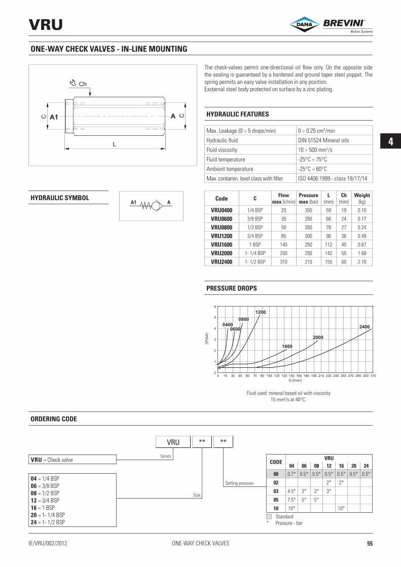
4
VRU
AA1
IE/VRU/002/2012
VRU ** **
L
Ch
C CAA1
Q (l/min)
P(b
ar)
00 15 30 45 60 75 90 105 120 135 150 165 180 195 210 225 240 255 270 285 300 315
1
2
3
4
5
6
0400
0600
0800
1200
1600
2000
2400
ONE-WAY CHECK VALVES
ONE-WAY CHECK VALVES - IN-LINE MOUNTING
The check-valves permit one-directional oil flow only. On the opposite side the sealing is guaranteed by a hardened and ground taper steel poppet. The spring permits an easy valve installation in any position.Exsternal steel body protected on surface by a zinc plating.
HYDRAULIC FEATURES
Max. Leakage (0 ÷ 5 drops/min) 0 ÷ 0.25 cm3/min
Hydraulic fluid DIN 51524 Mineral oils
Fluid viscosity 10 ÷ 500 mm2/s
Fluid temperature -25°C ÷ 75°C
Ambient temperature -25°C ÷ 60°C
Max. contamin. level class with filter ISO 4406:1999 - class 19/17/14
PRESSURE DROPS
HYDRAULIC SYMBOL
Fluid used: mineral based oil with viscosity 15 mm²/s at 40°C.
VRU = Check valve
ORDERING CODE
Series
Size
Setting pressure
Code C Flow max (l/min)
Pressure max (bar)
L(mm)
Ch(mm)
Weight(kg)
VRU0400 1/4 BSP 20 350 59 19 0.10
VRU0600 3/8 BSP 35 350 66 24 0.17
VRU0800 1/2 BSP 50 350 78 27 0.24
VRU1200 3/4 BSP 85 300 90 36 0.49
VRU1600 1 BSP 140 250 112 40 0.67
VRU2000 1- 1/4 BSP 200 250 142 55 1.68
VRU2400 1- 1/2 BSP 310 210 155 60 2.10
04 = 1/4 BSP06 = 3/8 BSP08 = 1/2 BSP12 = 3/4 BSP16 = 1 BSP20 = 1- 1/4 BSP24 = 1- 1/2 BSP
Standard* Pressure - bar
CODEVRU
04 06 08 12 16 20 2400 0.7* 0.5* 0.5* 0.5* 0.5* 0.5* 0.5*
02 2* 2*
03 4.5* 3* 3* 3*
05 7.5* 5* 5*
10 10* 10*
®
55

4
VUBA
A A1
A A1 VUBA08... VUBA12... A A1 VUBA04... VUBA06...
0
0.5
1.0
1.5
2.0
2.5
3.0
0 5 10 15 20 25 30 35 40 45 50
04
06
06
0
0.5
1.0
1.5
2.0
2.5
3.0
0 25 50 75 100 125 150
08 12
Ch
Ch I
G
A
VUBA..11..
VUBA..00..
C C
L
A
VUBA..12..
A1
A1
C C
ØM
ØF
ØN
A A1
E T
Q
H
C P
IE/VUBA/002/2012ONE-WAY CHECK VALVES
CHECK VALVES FOR PIPES
HYDRAULIC SYMBOL
HYDRAULIC FEATURES
Max. Leakage (0 ÷ 5 drops/min) 0 ÷ 0.25 cm3/min
Hydraulic fluid DIN 51524 Mineral oils
Fluid viscosity 10 ÷ 500 mm2/s
Fluid temperature -25°C ÷ 75°C
Ambient temperature -25°C ÷ 60°C
Max. contamin. level class with filter ISO 4406:1999 - class 19/17/14
DIAGRAMS FOR “T” ADJUSTEMENT
Code CFlow min
(l/min)
Flow max
(l/min)
Pressure max (bar)
E(mm)
F(mm)
G(mm)
H(mm)
I(mm)
L(mm)
M(mm)
N(mm)
P(mm)
Q(mm)
T *(mm)
Ch(mm)
Tightening torque
(Nm)
Weight (kg)
VUBA..00. VUBA..11. VUBA..12.
VUBA0400.. 1/4 BSP 4 25 350 8 0.5 - 0.60.8 - 1.01.2 - 1.31.5 - 1.9
2.0
11 17.5 61 61 2.4 8.5 9.5 5.5 0.2 ÷ 1.0 19 2 0.007 0.07 0.09
VUBA0600 .. 3/8 BSP 6 50 350 10.5 13 23 63 63 3.5 10.5 12.5 5.5 0.2 ÷ 2.0 22 3 0.012 0.10 0.11
VUBA0800 .. 1/2 BSP 16 80 350 12 14 25 72 65 4.5 13 15 7 0.4 ÷ 2.6 27 4 0.023 0.17 0.16
VUBA1200 .. 3/4 BSP 25 150 350 17 17 30.5 104 72 6 16 18 7 0.3 ÷ 2.8 32 10 0.047 0.25 0.21
Distance “T” must correspond to a flow rate of at least 50% top than the set flow.The flow of checking flow may be ±10% on given curve.Fluid used: mineral based oil with viscosity 46 mm²/s at 40°C.
Setti
ng T
(mm
)
Setti
ng T
(mm
)
Checking flow Q (l/min)Checking flow Q (l/min)
The pipe-pressure check valve is fitted directly on cylinder connections to pre-vent uncontrolled drops due to system faults.Supplied on request with a flow reducer hole F on the plate to enable leakage from A1 to A and allow the load to drop slowly.Steel body and plate. Seal surfaces lapped.
* Specify distance “T” with decimal progression. Standard distance “T” is 0.5 mm (for 1/4 and 3/8 BSP valves) and 0.7 mm (for 1/2 and 3/4 BSP valves). Response flow depends on distance “T” see “T adjustment curves”.
®
56

4
VUBA
IE/VUBA/002/2012
ØD
L
L1
L2
SEDE
C H (mm)
1/4 BSP 113/8 BSP 111/2 BSP 153/4 BSP 16
VUBA04... VUBA06... VUBA08... VUBA12...
A
A1
A A1 A A1A A1A A1
Q (l/min)
P(b
ar)
0
1
2
3
4
5
6
7
8
0 12 24 36 48 60 72 84
T=
0.5
T=
1
T= 1
.2
Q (l/min)
P(b
ar)
0
1
2
3
4
5
6
7
8
0 5 10 15 20 25 30 35
T=
0.5
T=
1
T=
0.2
Q (l/min)
P(b
ar)
0
1
2
3
4
5
6
7
8
0 8 16 24 32 40 48 56T
= 0
.5
T= 1
T=
1.2
T=
2.0
T=
0.2
Q (l/min)
P(b
ar)
0
1
2
3
4
5
7
6
8
0 25 50 75 100 125 150 175
T=
0.5
T=
1
T= 2
.5
T=
1.5
C
H m
in
VUBA ** ** T*** F**
ONE-WAY CHECK VALVES
KEY FOR TIGHTENING VALVE
SEAL
FLOW PRESSURE DROP ACCORDING ADJUSTEMENT “T”
Code key
For valve
D(mm)
L(mm)
L1(mm)
L2(mm)
AVA184 VUBA04.. 11.3 120 110 60AVA186 VUBA06.. 15 120 110 80AVA188 VUBA08.. 18.8 120 108 80AVA1812 VUBA12.. 24 120 108 80
Diagrams flow pressure drop according adjustement length of “T”
ORDERING CODE
SERVICE EXAMPLE
Series
Size
Versions
Setting T
Hole on the plate
VUBA = Check valve
04 = 1/4 BSP06 = 3/8 BSP08 = 1/2 BSP12 = 3/4 BSP
00 = Cartridge only11 = Complete valve M/F12 = Complete valve F/F01 = Only column M/F02 = Only column F/F
Standard, without hole (omit code)
Special holes (1)
05 = 0.5 (mm)06 = 0.6 (mm)08 = 0.8 (mm)10 = 1.0 (mm)12 = 1.2 (mm)
13 = 1.3 (mm)15 = 1.5 (mm)19 = 1.9 (mm)20 = 2.0 (mm)
Standard settings (omit code)0.5 mm for dimensions 04-060.7 mm for dimensions 08-12
Special settings (2)
020 ÷100 = 0.2 ÷ 1.0 mm for dimension 04020 ÷200 = 0.2 ÷ 2.0 mm for dimension 06040 ÷260 = 0.4 ÷ 2.6 mm for dimension 08030 ÷280 = 0.3 ÷ 2.8 mm for dimension 12
NOTE:(1-2) Special, minimum 100 pieces.(2) Specify distance “T” with decimal progression (e.g. T020 = 0.20 mm).
®
57

4
SH01
IE/SH01/000/2016
New!
1
2
3
SH 01 00 1
Q (l/min)
0
1
2
3
7
4
8
5
9
6
10
0 0.2 0.4 0.6 0.8 1.0 1.2 1.4 1.6 1.8 2.0
P(b
ar)
1 2
3 2
3
12.8
Ø6.1
Ø6.5
Ø 9
25
M8X
x1
1
23
ONE-WAY CHECK VALVES
The shuttle type cartridge valves allow taking of the highest pressure signal to the external port via displacement of tempered and ground steel ball. There are usually employed to signal the actuator load to a load sensing pump pres-sure compensator. External steel body.
HYDRAULIC FEATURES
Max. working pressure 350 bar
Max. Flow 2 l/min
Hydraulic fluid DIN 51524 Mineral oils
Fluid viscosity 10 ÷ 500 mm2/s
Fluid temperature -25°C ÷ 75°C
Ambient temperature -25°C ÷ 60°C
Max. contamin. level class with filter ISO 4406:1999 - class 19/17/14
Weight 0.0065 kg
Tightening torque 16 ÷ 18 Nm
Cavity (M8 x 1) CA007001 (See section 17)
HYDRAULIC SYMBOL
SH = Shuttle valve
01 = M8 x 1
ORDERING CODE
1 = Serial No.Series
Size 00 = No variants
Fluid used: mineral based oil with viscosity 32 mm²/s at 40°C.
PRESSURE DROPS
Variants
00012040 Spare seals kit
®
58

4
SH02
1
2
3
SH 02 00 2
IE/SH02/002/2013
Q (l/min)
0
1
2
3
7
4
5
6
8
0 1 2 3 4 5 6 7 8
P(b
ar)
3 2
1 2
2
13
1/8
"B
SP
P
4
5
Ø 7
.6
Ø 8
18
ONE-WAY CHECK VALVES
SHUTTLE VALVES
The shuttle type cartridge valves allow taking of the highest pressure signal to the external port via displacement of tempered and ground steel ball. There are usually employed to signal the actuator load to a load sensing pump pres-sure compensator. External steel body.
HYDRAULIC FEATURES
Max. working pressure 400 bar
Max. Flow 8 l/min
Hydraulic fluid DIN 51524 Mineral oils
Fluid viscosity 10 ÷ 500 mm2/s
Fluid temperature -25°C ÷ 75°C
Ambient temperature -25°C ÷ 60°C
Max. contamin. level class with filter ISO 4406:1999 - class 19/17/14
Weight 0.006 kg
Tightening torque 16 ÷ 18 Nm
Cavity (G 1/8) CG001002 (See section 17)
HYDRAULIC SYMBOL
SH = Shuttle valve
02 = 1/8 BSP
ORDERING CODE
2 = Serial No.Series
Size 00 = No variants
Fluid used: mineral based oil with viscosity 46 mm²/s at 40°C.
PRESSURE DROPS
Variants
Q25880009 Polyurethane spare seals kit -35°C ÷ 100°C
®
59

4
SH03
1
2
3
IE/SH03/001/2011
SH 03 ** 2
Q (l/min)
P(b
ar)
0
1
2
3
4
5
6
7
8
0 1 2 3 4 5
1 2
3 2
Ø 1
0
1/4
" B
SP
21
3
5
14
36
19,45
ONE-WAY CHECK VALVES
SHUTTLE VALVES
The shuttle type cartridge valves allow taking of the highest pressure signal to the external port via displacement of ball in tempered and ground steel. There are usually employed to signal the actuator load to a load sensing pump pressure compensator. External steel body protected on surface by zinc plat-ing.
HYDRAULIC FEATURES
Max. working pressure 350 bar
Max. Flow 5 l/min
Max. Leakage (0 ÷ 5 drops/min) 0 ÷ 0.25 cm3/min
Hydraulic fluid DIN 51524 Mineral oils
Fluid viscosity 10 ÷ 500 mm2/s
Fluid temperature -25°C ÷ 75°C
Ambient temperature -25°C ÷ 60°C
Max. contamin. level class with filter ISO 4406:1999 - class 19/17/14
Weight 0.023 kg
Tightening torque 18 ÷ 20 Nm
Cavity (1/4 BSP) CA012001 (See section 17)
PRESSURE DROPS
HYDRAULIC SYMBOL
CRI = Shuttle valve
03 = 1/4 BSP
ORDERING CODE
2 = Serial No.Series
Size 00 = No variantsV1 = Viton
Fluid used: mineral based oil with viscosity 46 mm²/s at 40°C.
Variants
00012019 Spare seals kit
®
60

4
RVLV0
3
2
1
Q (l/min)
P(b
ar)
0
5
10
15
20
25
30
35
0 2 4 6 8 10 12 14 16 18 20
3 2
1 2
1
23
6
12
x1
.5
16
.5
35.5
22
M1
6
12
.5
IE/RVLV0/001/2011 ONE-WAY CHECK VALVES
SHUTTLE VALVES
The shuttle type cartridge valves allow taking of the highest pressure signal to the external port via displacement of ball in tempered and ground steel. There are usually employed to signal the actuator load to a load sensing pump pressure compensator. External steel body protected on surface by zinc plat-ing.
HYDRAULIC FEATURES
Max. working pressure 380 bar
Max. Flow 10 l/min
Max. Leakage (0 ÷ 5 drops/min) 0 ÷ 0.25 cm3/min
Hydraulic fluid DIN 51524 Mineral oils
Fluid viscosity 10 ÷ 500 mm2/s
Fluid temperature -25°C ÷ 75°C
Ambient temperature -25°C ÷ 60°C
Max. contamin. level class with filter ISO 4406:1999 - class 19/17/14
Weight 0.029 kg
Tightening torque 16 ÷ 18 Nm
Cavity (M16x1.5) CN037003 (See section 17)
HYDRAULIC SYMBOL
ORDERING CODE
Code Type
RVLV0101160 Shuttle valve
PRESSURE DROPS
Fluid used: mineral based oil with viscosity 46 mm²/s at 40°C.
00012020 Spare seals kit
®
61

4
RVLV1
IE/RVLV1/001/2011
Q (l/min)
P(b
ar)
0
2
4
6
8
0 20 40 60 80 100 120 140
2 1
1
2
X
30
1
2
X 21
.5
40.5
52
M2
7 x
1.5
A
A = 1/4 BSP (RVLV1..2270)
SAE 7/16 20UNF (RVLV1..2150)
ONE-WAY CHECK VALVES
PUMP UNLOADING VALVES
HYDRAULIC FEATURES
Max. working pressure 380 bar
Max. Flow 140 l/min
Max. Leakage (0 ÷ 5 drops/min) 0 ÷ 0.25 cm3/min
Hydraulic fluid DIN 51524 Mineral oils
Fluid viscosity 10 ÷ 500 mm2/s
Fluid temperature -25°C ÷ 75°C
Ambient temperature -25°C ÷ 60°C
Max. contamin. level class with filter ISO 4406:1999 - class 19/17/14
Weight 0.1422 kg
Tightening torque 22 ÷ 26 Nm
Cavity (M27x1.5) CN059001 (See section 17)
HYDRAULIC SYMBOL
ORDERING CODE
Code Type
RVLV1202270 Pump unloading valve (A = 1/4 BSP)
RVLV12021S0 Pump unloading valve (A = SAE 7/16 20UNF)
PRESSURE DROPS
Fluid used: mineral based oil with viscosity 46 mm²/s at 40°C.
The normally-closed 2-way 2-position valve is used to connect a normally pressurised branch to the outlet in order to allow fluid to flow through the valve from 2 to 1.Tapered poppet in tempered and ground steel, released when the pilot branch X is connected to the outlet. It has a galvanised steel body.
00012021 Spare seals kit
®
62

5
5IE/C5/001/2016 PILOT CHECK VALVES
PILOT CHECK VALVES
®
63

5
VRS
A
X
A1
Q (l/min)
0
1
2
3
0 10 20 30 40 50 9060 8070
VRS 7
VRS 10
VRS 13VRS 19
P(b
ar)
Q (l/min)
0
1
2
3
0 10 20 30 40 50 9060 8070
VRS 7 VRS 19
VRS 10 VRS 13
P(b
ar)
VRS ** 1 00 1
A A1A A1
AD D
x
d
L CH
A1
IE/VRS/001/2011PILOT CHECK VALVES
SINGLE ACTING PILOTED CHECK VALVES - IN-LINE MOUNTING
HYDRAULIC FEATURES
Max. working pressure 350 bar
Standard opening pressure 0.5 bar
Max. Leakage (0 ÷ 20 drops/min) 0 ÷ 1 cm3/min
Piloting ratio See table
Max. Flow 85 l/min
Hydraulic fluid DIN 51524 Mineral oils
Fluid viscosity 2.8 ÷ 380 mm2/s
Fluid temperature -25°C ÷ 75°C
Ambient temperature -25°C ÷ 60°C
Max. contamin. level class with filter ISO 4406:1999 - class 19/17/14
Weight See table
PRESSURE DROPS - FLOWHYDRAULIC SYMBOL
VRS = Simple acting piloted check valves
07 = 1/4 BSP - 1/4 BSP10 = 1/4 BSP - 3/8 BSP13 = 1/4 BSP - 1/2 BSP19 = 1/4 BSP - 3/4 BSP
ORDERING CODE
1 = Serial No.Series
Size00 = No variants
Fluid used: mineral based oil with viscosity 24 mm²/s at 50°C.
Code Flow max (l/min)
Pressure max (bar)
L(mm)
Ch(mm)
Pilotingratio d D Weight
(kg)
VRS07 12 350 103 36 1:9 1/4 BSP 1/4 BSP 0.65
VRS10 30 310 109 40 1:6 1/4 BSP 3/8 BSP 0.82
VRS13 45 310 120 42 1:4.5 1/4 BSP 1/2 BSP 0.96
VRS19 85 300 131 55 1:3.7 1/4 BSP 3/4 BSP 1.95
1 = Opening pressure 0.5 bar (standard)
Variants
The pilot-operated check valve blocks a single-acting actuator in any position. Tapered poppet in tempered and ground steel, released by feeding the piloted opening X.Can be mounted in any position; galvanised.
®
64

5
VBPSA-VBPDA
IE/VBPSA-VBPDA/001/2011
A1
A
B1
B
A1
A
B1
B
VBPSA VBPDA
A1
A
B1
B
P
R
A1
A
C C
D
E
B
B1
CM
L
H
C
NGF
PILOT CHECK VALVES
Code CFlow max
(l/min)
Pressure max (bar)
D(mm)
E (mm)
F (mm)
G (mm)
H (mm)
L (mm)
M(mm)
N (mm)
P(mm)
R (mm)
Weight (kg)
Pilotratio
VBPSA0400 1/4 BSP 20 350 30 60 20 27 45 6.5 9 30 117 70 0.76 1:4
VBPSA0600 3/8 BSP 25 350 30 60 20 27 45 6.5 9 30 117 70 0.72 1:4
VBPSA0918 9/16-18 UNF 20 350 30 60 30.5 30.5 45 6.5 9 30 131 70 0.72 1:4
VBPSA0800 1/2 BSP 45 300 40 75 35 42 60 8 17 40 170 90 1.65 1:4
VBPSA1200 3/4 BSP 85 280 60 104 46 46 70 9 16 50 212 120 3.10 1:3.6
VBPDA0400 1/4 BSP 20 350 30 60 27 27 45 6.5 9 30 124 70 0.80 1:4
VBPDA0600 3/8 BSP 25 350 30 60 27 27 45 6.5 9 30 124 70 0.75 1:4
VBPDA0918 9/16-18 UNF 20 350 30 60 30.5 30.5 45 6.5 9 30 131 70 0.75 1:4
VBPDA0800 1/2 BSP 45 300 40 75 42 42 60 8 17 40 174 90 1.78 1:4
VBPDA1200 3/4 BSP 85 280 60 104 46 46 70 9 16 50 212 120 3.25 1:3.6
SINGLE AND DOUBLE ACTING PILOT CHECK VALVES - IN-LINE MOUNTING
With the acting pilot check valves, a single or double acting actuator can be locked in any position. Sealing is guaranteed by tempered, ground, tapered steel poppets, releasing is by venting the piloted openings “A” and “B” according to the valve pilot ratio. The valves can be mounted in any position and are protected externally by a zinc plating.
HYDRAULIC FEATURES
Max. Leakage (0 ÷ 5 drops/min) 0 ÷ 0.25 cm3/min
Hydraulic fluid DIN 51524 Mineral oils
Fluid viscosity 10 ÷ 500 mm2/s
Fluid temperature -25°C ÷ 75°C
Ambient temperature -25°C ÷ 60°C
Max. contamin. level class with filter ISO 4406:1999 - class 19/17/14
HYDRAULIC SYMBOLS SERVICE EXAMPLE
®
65

5
VBPSA-VBPDA
VBP ** ** **
VBPSA 0400-0918
VBPDA 0400-0918
Q (l/min)
P(b
ar)
0
1
2
3
4
5
6
0 5 10 15 20 25
A A1
B B1
(1)
VBPSA 0400-0918
VBPDA 0400-0918
A1 A
B1 B
Q (l/min)
P(b
ar)
0
1
2
3
4
5
6
0 5 10 15 20 25
(1)
VBPSA 0600
VBPDA 0600
A A1
B B1
Q (l/min)
P(b
ar)
0
1
2
3
4
5
6
0 5 10 15 20 25
(1)
VBPSA 0600
VBPDA 0600
A1 A
B1 B
Q (l/min)
P(b
ar)
0
1
2
3
4
5
6
0 5 10 15 20 25
(1)
VBPSA 0800
VBPDA 0800
A A1
B B1
Q (l/min)
P(b
ar)
0
1
2
3
4
5
6
0 10 20 30 40 50
(1)
P(b
ar)
VBPSA 0800
VBPDA 0800
A1 A
B1 B
Q (l/min)
0
1
2
3
4
5
6
0 10 20 30 40 50
(1)
VBPSA 1200
VBPDA 1200
A A1
B B1
Q (l/min)
P(b
ar)
0
1
2
3
4
5
6
0 10 20 6030 7040 8050 90
(2)
VBPSA 1200
VBPDA 1200
A1 A
B1 B
Q (l/min)
P(b
ar)
0
1
2
3
4
5
6
0 10 20 30 6040 7050 80 90
(2)
IE/VBPSA-VBPDA/001/2011PILOT CHECK VALVES
PRESSURE DROPS
VBP = Acting pilot check valve..
ORDERING CODE
Series
Type
(1) Fluid used: mineral based oil with viscosity 15 mm²/s at 40°C.(2) Fluid used: mineral based oil with viscosity 24 mm²/s at 50°C.
SA = ..one user portDA = ..port A and B
Size
04 00 = 1/4 BSP06 00 = 3/8 BSP08 00 = 1/2 BSP12 00 = 3/4 BSP09 18 = 9/16 18UNF
®
66

5
VBPSA-VBPDA DIN
IE/VBPSA-VBPDA-DIN/001/2011
A1
A
B1
B
A1
A
B1
B
VBPSA VBPDA
A1
A
B1
B
C C
D
E
M
24
°
H
N
M18x1.5 L
Ste
el pip
e -
Tubo Ø
12
R
A
A1 B1
B
P
G
DIN 2353
PILOT CHECK VALVES
SINGLE AND DOUBLE ACTING PILOT CHECK VALVES-DIN 2353 PORTS - IN-LINE MOUNTING
With the acting pilot check valves, a single or double acting actuator can be locked in any position. Sealing is guaranteed by tempered, ground, tapered steel poppets, releasing is by venting the piloted openings “A” and “B” according to the valve pilot ratio. The valves can be mounted in any position and are protected externally by a zinc plating.
HYDRAULIC FEATURES
Max. Leakage (0 ÷ 5 drops/min) 0 ÷ 0.25 cm3/min
Hydraulic fluid DIN 51524 Mineral oils
Fluid viscosity 10 ÷ 500 mm2/s
Fluid temperature -25°C ÷ 75°C
Ambient temperature -25°C ÷ 60°C
Max. contamin. level class with filter ISO 4406:1999 - class 19/17/14
HYDRAULIC SYMBOLS SERVICE EXAMPLE
Code CFlow max
(l/min)
Pressure max (bar)
D(mm)
E (mm)
G (mm)
H (mm)
L (mm)
M(mm)
N (mm)
P(mm)
R (mm)
Weight(kg)
Pilotratio
VBPSA0412 1/4 BSP 20 350 30 60 22.5 45 6.5 9 30 115 70 0.83 1:4
VBPSA0612 3/8 BSP 25 350 30 60 22.5 45 6.5 9 30 115 70 0.75 1:4
VBPDA0412 1/4 BSP 20 350 30 60 22.5 45 6.5 9 30 115 70 0.83 1:4
VBPDA0612 3/8 BSP 25 350 30 60 22.5 45 6.5 9 30 115 70 0.75 1:4
®
67

5
VBP ** ** 12
VBPSA-VBPDA DIN
VBPSA 0412
VBPDA 0412
A A1
B B1
Q (l/min)
P(b
ar)
0
1
2
3
4
5
6
0 5 10 15 20 25
VBPSA 0412
VBPDA 0412
A1 A
B1 B
Q (l/min)
P(b
ar)
0
1
2
3
4
5
6
0 5 10 15 20 25
VBPSA 0612
VBPDA 0612
A A1
B B1
Q (l/min)
P(b
ar)
0
1
2
3
4
5
6
0 5 10 15 20 25
VBPSA 0612
VBPDA 0612
A1 A
B1 B
Q (l/min)
P(b
ar)
0
1
2
3
4
5
6
0 5 10 15 20 25
Ø12
DIN 2353
17x22x1.5
Ø28
Ø12
40
Ø 3
/8
DIN 2353
24°
Ø28
M18
30
Ø 3
/8
31
3/8 BSP
2 1
Q51435044
RF05060000
OT0506T12
OD050612L
1: E341L122: E342L12
IE/VBPSA-VBPDA-DIN/001/2011PILOT CHECK VALVES
PRESSURE DROPS
VBP = Acting pilot check valve..
ORDERING CODE
Series
Type
Fluid used: mineral based oil with viscosity 15 mm²/s at 40°C.
SA = ..one user portDA = ..port A and B
Size 04 12 = 1/4 BSP - Steel pipe E1206 12 = 3/8 BSP - Steel pipe E12
ACCESSORIES AND SPARE PARTS
Nut (spare)Cutting ring (spare)
Copper Washer
Banjo
DIN Banjo
Hollow screw
Assembly example with steel pipe Ø 12 mm
®
68

6
IE/C6/001/2016 MANUAL AND PNEUMATIC OPERATED VALVES
MANUAL AND PNEUMATIC OPERATED VALVES
®
69

6
CMF04
2
1
2
1
CMF 04 * 0 0 1
Q (l/min)
P(b
ar)
0
1
2
3
4
5
6
7
8
9
10
0 5 15 20 2510
3/4 - 16 UNF
2
1
46/51
25° 27°
Ø .12 7
25
27
18
9.5
3 (N°2)
4 Nm
Mic
roin
terr
uttore
/ M
icro
sw
itch
25-30 Nm
13
24
10÷12 Nm
IE/CMF04/ 003/2016MANUAL AND PNEUMATIC OPERATED VALVES
LEVER OPERATED VALVES
HYDRAULIC FEATURES
HYDRAULIC SYMBOLS
L = Without microswitchM = With microswitch
CMF = Lever operated valve
04 = 3/4 - 16 UNF
ORDERING CODE
Series
Size
1 = Serial No.
0 = No variants
0 = Vertical positioning (Standard) See drawing
CMF04LWithout microswitch
CMF04MWith microswitch
Version
Max. working pressure 300 barMax. Flow 25 l/minMax. Leakage (0 ÷ 5 drops/min) 0 ÷ 0.25 cm3/minWorking Temperature -25°C ÷ 60°CHydraulic fluid DIN 51524 Mineral oilsFluid viscosity 10 ÷ 500 mm2/sFluid temperature -25°C ÷ 75°CMax. contamin. level class with filter ISO 4406:1999 - class 19/17/14Tightening torque 25 ÷ 30 NmWeight 0.25 kgCavity (3/4 - 16 UNF) CD018014 (See section 17)
Fluid used: mineral based oil with viscosity 32 mm²/s at 40°C.
PRESSURE DROPS (With valve completely open)
Variants
The direct acting, normally closed 2-way 2 position directional valve with manual control releases (load sensitive) pressure enabling fluid to flow through the valve from 2 to 1.Tapered poppet is in tempered and ground steel. Micro switch controlling a motor-driven pump relay supplied on request.The lever body is in die-cast aluminium and the valve body in galvanised steel.
00012003 Spare seals kit
Microswitch versionMechanical life endurance at 250 Vac 10A (1E4) - 5A (5E4)Protection degree with connector IP40
®
70

6
CPE04
2
1
IE/CPE04/003/2016
CPE 04 P0 00 • 1
Q (l/min)
P(b
ar)
0
2
4
6
8
10
12
14
16
18
20
0 2 4 6 8 10 12 14 16 18 20 22 24 26 28 30
2 1
1 2
0
10
20
30
40
50
60
0 100 200 300 400
F (
daN
)
P(bar)
2 1
1 2
3/4
- 1
6 U
NF
1
2
70.1
42
Ø 1
2.7
Ø 2
2
27.8 0.3
3
22
MANUAL AND PNEUMATIC OPERATED VALVES
BUTTON OPERATED VALVES
HYDRAULIC SYMBOL
PRESSURE DROPS
Fluid used: mineral based oil with viscosity 32 mm²/s at 40°C.
HYDRAULIC FEATURES
CPE = Button operated valve
ORDERING CODE
Series
Size
Version
04 = 3/4 - 16 UNF
P0 = Starting by push button
1 = Serial No.
Max. working pressure 300 bar
Max. Flow 30 l/min
Max. Leakage (0 ÷ 20 drops/min) 0 ÷ 1 cm3/min
Hydraulic fluid DIN 51524 Mineral oils
Fluid viscosity 10 ÷ 500 mm2/s
Fluid temperature -25°C ÷ 75°C
Ambient temperature -25°C ÷ 60°C
Max. contamin. level class with filter ISO 4406:1999 - class 19/17/14
Weight 0.107 kg
Tightening torque 25 ÷ 30 Nm
Cavity (3/4 - 16 UNF) CD018006 (See section 17)
OPERAT. FORCE ON THE PUSH BUTTON
Fluid used: mineral based oil with viscosity 32 mm²/s at 40°C.
Variants
The direct acting, normally closed 2-way 2 position directional valve with manual control is used for emergencies. It is opened by pressing the button. The bi-directional tapered poppet is in tempered and ground steel. The valve body is in galvanised steel.
00012003 Spare seals kit
00 = No variantsFH = Mesh filter
®
71

6
CRD04P
P(b
ar)
Q (l/min)
0
2
4
6
8
10
12
14
0 2 4 6 8 10 12 14 16 18 20 22 24 26 28 30
2 1
1 2
2
1
X
CRD 04 P NC A ** 2
2 1 1 2
36
1
2
49,4
14 4.9.5
3/4-16 UNF
Ø.
12
7
27 4.
Ø2
3
76 8.
X
1/8
"BS
P
P(b
ar)
Q (l/min)
0
25
50
75
100
125
150
175
200
225
250
0 2 4 6 8 10 12 14 16 18 20 22 24 26 28 30
IE/CRD04P/003/2016MANUAL AND PNEUMATIC OPERATED VALVES
HYDRAULIC SYMBOL
Fluid used: mineral based oil with viscosity 46 mm²/s at 40°C.
HYDRAULIC FEATURES
Max. working pressure 250 barMin. piloting pressure 1 2Min. piloting pressure 2 1Max. piloting pressure
5.5 bar3.5 bar20 bar
Max. Flow 30 l/min
Max. Leakage (0 ÷ 20 drops/min) 0 ÷ 1 cm3/min
Hydraulic fluid DIN 51524 Mineral oils
Fluid viscosity 10 ÷ 500 mm2/s
Fluid temperature -25°C ÷ 75°C
Ambient temperature -25°C ÷ 60°C
Max. contamin. level class with filter ISO 4406:1999 - class 19/17/14
Weight 0.107 kg
Tightening torque 25 ÷ 30 Nm
Cavity (3/4 - 16 UNF) CD018006 (See section 17)
PRESSURE DROPS LIMITS OF USE
PNEUMATIC OPERATED VALVES
CRD = Pneumatic operated valve
ORDERING CODE
Series
Size
Control
04 = 3/4 - 16 UNF
P = Pneumatic
2 = Serial No.
00 = No variantsFH = Mesh filter
Variants
The direct acting, bi-directional way normally closed 2-way 2 position valve with pneumatic control releases the pressure enabling fluid to flow through the valve in both directions.The bi-directional tapered poppet is in tempered and ground steel, released when the pilot branch X is connected to a pneumatic pressure signal.The valve body is in galvanised steel.
00012003 Spare seals kit
A = Standard - Ø12.7mm
NC = Normally closed
®
72

7
IE/C7/001/2016 END-OFF STROKE VALVES
END-OFF STROKE VALVES
®
73

7
VFC
B
A
Q (l/min)
P(b
ar)
0
2
4
6
8
0 10 30 4020
VFC 06 OR
B
F
A
93/8 BSP
Ø8
.5
50
30
89
49
65
24
915
6 corsa
stroke
35
Ø1
0
IE/VFC/002/2012END-OFF STROKE VALVES
END-OFF STROKE VALVES - IN-LINE MOUNTING
HYDRAULIC SYMBOL
HYDRAULIC FEATURES
ORDERING CODE
Max. working pressure 300 bar
Max. Flow 40 l/min
Max. Leakage (0 ÷ 5 drops/min) 0 ÷ 0.25 cm3/minMax. mechanical push force (F)required at 300 bar 240 daN
Hydraulic fluid DIN 51524 Mineral oils
Fluid viscosity 10 ÷ 500 mm2/s
Fluid temperature -25°C ÷ 75°C
Ambient temperature -25°C ÷ 60°C
Max. contamin. level class with filter ISO 4406:1999 - class 19/17/14
Weight 0.68 kg
PRESSURE DROPS
Fluid used: mineral based oil with viscosity 15 mm²/s at 40°C.
Series
06 = 3/8 BSPSize
OR = Type
VFC = End-off stroke valves
The direct acting normally closed 2-way 2-position directional valve with manual control is fitted on a branch to release the pressure; a pusher enables the fluid to pass through the valve from A to B.Tapered poppet is in tempered and ground steel.The valve body is in galvanised steel.
®
74

7
VD40
P
Y
A
IE/VD40/001/2011
VD 40 A ** 3
Q (l/min)
L(m
m)
104
106
108
110
112
114
116
118
120
0 10 20 30 40
180 bar
80 bar
Ø 1
4
Ø 8
.5
59
.5
8.5
14
8.5
Lm
in1
03
Lm
ax
12
3.5
11
5
38
62
18
23
59.5
95
45
45
14.5 8.5
P
½" BSP
1/8" BSP
½" BSP
½" BSP
A
Y
P
A
F
END-OFF STROKE VALVES
DECELERATION VALVES - IN-LINE MOUNTING
These valves are used as cam controlled unidirectional flow regulators.Normally mounted in line between actuator and directional valve for the dis-placement of carriages or slides, they enable cam controlled acceleration or deceleration of the moving mass.A special internal check valve allows free flow the opposite direction.To ensure correct functionning, connect “Y” to draining line.
HYDRAULIC SYMBOL
HYDRAULIC FEATURES
VD = Deceleration valve
ORDERING CODE
Series
Thread
40 = Flow rate 40 l/min
A = 1/2” BSP
3 = Serial No.
00 = No variantsV1 = VitonFA = Not complete closing to avoid the “jump” in the controlled actuator
Max. working pressure 180 bar
Max. Flow 40 l/min
Max. Leakage 0.06 l/min
Cam travel See diagram
Max. mechanical push force (F) 100 N
Hydraulic fluid DIN 51524 Mineral oils
Fluid viscosity 10 ÷ 500 mm2/s
Fluid temperature -25°C ÷ 75°C
Ambient temperature -25°C ÷ 60°C
Max. contamin. level class with filter ISO 4406:1999 - class 19/17/14
Weight 2.8 kg
FLOW RATE / Lmin-Lmax
Fixing screws UNI 5931 M8x50, material specifications 12.9Tightening torque 8 Nm / 0.8 Kgm
Variants
®
75

7
END-OFF STROKE VALVES
®
76

8
IE/C8/001/2016 SOLENOID VALVES 2-WAY
SOLENOID VALVES 2-WAY
®
77

8
3 3 Corsa.
(Stroke)
2.3 Corsa
2.3 Corsa
(Stroke)
(Stroke)
max 7 Nm
max 7 Nm
max 7 Nm
38 2 max.
29 5.
27
Ø01
82.3 Corsa(Stroke)
3/4 - 16 UNF
2
1
93.6 (NA)
38 6. (*)
Ø.
12 7
Ø20
Ø20.3
Ø21
Ø10
Ø10
Ø10
2 5.
27 30
66 6. (NA)
59 (NC)
86 (NC)
P4
E9
P3
42
20 5.
19
24
Emergenza (NA)Emergency (NA)
(*) 13.3 (NA)13 (NC)
CRB04 / CRP04
1
2 2
1
1
2 2
1
IE/CRP04/009/2018
Ø 1
2.7
Ø 1
5.8
7
SOLENOID VALVES 2-WAY
PILOTED OPERATED SOLENOID VALVE
FEATURES
HYDRAULIC SYMBOLS
Max. pressure 300 bar (*)
Max. Flow 40 l/min
Max. Leakage (0 ÷ 10 drops/min) 0 ÷ 0.5 cm3/min
Max. excitation frequency 2 Hz
Duty cycle 100% ED
Hydraulic fluids DIN 51524 Mineral oils
Fluid viscosity 10 ÷ 500 mm²/s
Fluid temperature -25°C ÷ 75°C
Ambient temperature -25°C ÷ 60°C
Max. contamin. level class with filter ISO 4406:1999 - class 19/17/14
Cartridge filter 280µmType of protection (in relation to the connection used) IP65
Weight (with coil) 0.27 kg
Cartridge tightening torque 25 ÷ 30 Nm
Coil ring nut tightening torqueEmergency tightening torque 7 Nm
Cavity standard “A”(3/4 - 16 UNF)
CD018006 (See section 17)
Cavity standard “A”+ seat VSCOA**01
CD018009 (See section 17)
Cavity with reduction “B”(3/4 - 16 UNF)
CD018012 (See section 17)
CRP - Normally open CRP - Normally closed
CRP 04 18.. Cavity type “A”
Emergency (NC)
Variants (NA)
Connector to be ordered separately, see sect. 20
The pilot-operated electric 2-way 2-position directional valve is controlled electrically.The tapered poppet is in tempered and ground steel.Available in normally open (NA) or normally closed (NC) versions.
00012023 Spare seals kit
Removable cup
CRB - Normally open CRB - Normally closed
Valve Free passage Coil Type
CRP..NA 2 → 1 DE-ENERGISED
UnidirectionalCRP..NC
2 → 1 ENERGISED
1 → 2 DE-ENERGISED
CRB..NA1 → 2
DE-ENERGISED
Bidirectional2 → 1
CRB..NC1 → 2 ENERGISED / DE-ENERGISED
2 → 1 ENERGISED
AC normally closed valves (NC) can work also with coils in DC.Normally open valves work with DC coils whereas RAC coils with a connector and incorporated rectifier must be used for AC applications. The NC valve sleeve is in galvanised steel and the NA valve sleeve with nikel coated.
Reduction for cavity type “B”
V89B30000 Spare code
(*) 80000 cycles at 300 bar / 200000 cycles at 210 bar
®
78

8
CRB..NA (1 → 2 2 → 1)CRP..NA (2 → 1)
CRB..NC ( 2 → 1)CRP..NC ( 2 → 1)
CRB..NC (1 → 2)CRP..NC (1 → 2)
CRB04 / CRP04
IE/CRP04/009/2018
CR* 04 18 ** * * * ** *
Q (l/min)
P(b
ar)
0
2
4
6
8
10
12
14
16
0 10 20 30 40
Q (l/min)
P(b
ar)
0
2
4
6
8
10
12
14
16
0 10 20 30 40
Q (l/min)
P(b
ar)
0
2
4
6
8
10
12
14
16
18
20
22
0 10 20 30 40
Q (l/min)
P(b
ar)
0
50
100
150
200
250
300
0 10 20 30 40
CRB..NC / CRP..NC
CRB..NC
CRB / CRP..NACRB / CRP..NC
SOLENOID VALVES 2-WAY
ORDERING CODE
PRESSURE DROPS
Series
Size
Version
Coil
Version
Seat size
LIMITS OF USE
The tests were carried out with the solenoids at operating temperature, with a supply voltage 10% below nominal value and with a 40°C fluid temperature. The fluid used is a mineral oil with viscosity of 46 mm²/s at 40°C.
Voltage
Variants
Connector to be ordered separately, see sect. 20
(1) Only voltages 12 VDC - 24 VDC(2) Only voltages 12 VDC - 24 VDC(3) With rectifier: 24 VAC/50-60Hz(4) With rectifier: 115 VAC/50Hz - 120VAC/60Hz
(5) With rectifier: 230 VAC/50Hz - 240VAC/60Hz(6) Performance are guaranteed only using valves completed with BFP coil(7) Only for NC valves(8) Tested for working in AC and DC
04 = 3/4 - 16 UNF
NA = Normally open (solo con bobine DC o RAC)
NC = Normally closed
18 = 18W dc (NA-NC) - C30
A = Standard - Ø 12.7 mmB = With reduction - Ø 15.9 mm
S = Without emergency (NC)E = With emergency (NA-NC)
1 = CRB - Serial No.3 = CRP - Serial No.
DC 18W (C30) AC 18W (C30) (7)
L = 12 VDCM = 24 VDCN = 48 VDC2 = 21.6 VDC RAC (3)Z = 102 VDC RAC (4)X = 205 VDC RAC (5)W = Without coil (6)
A = 24 VAC 50 HzJ = 115 VAC 50 HzI = 230 VAC 50 HzF = 24 VAC 60 HzC = 110 VAC 60 HzD = 220 VAC 60 HzK = Without coil (6-8)
Coils technical data, see sect. 19
00 = No variants P4 = Push button Emergency with removable protection (..NA)P3 = Rotary Emergency (..NA)E9 = Push button Emergency direct control (..NA)SF = Without cartridge filterFK = With flying leads 600 mm (1)CX = Deutsch connection with bidirectional diode (2)
CRB = Piloted solenoid valve bidirectional
CRP = Piloted solenoid valve unidirectional
de-energised
energised
®
79

8
CRP04HP
1
2
1
2
CRP 04 HP NA ..
CRP 04 HP NC ..
10
3 Corsa(Stroke)
P3 38 2 max.
2
1
3/4-16 UNF
20
12 7.
61 8.
2 5.
88 8.
278 8.38 5.
47.8
23 5.
36
19
24
8
4 corsa(stroke)
36
47
.8
23
5.
2
1
85 2.
27
12
7.
38 5. 11.8
3/4-16 UNF
3
20
8
93 2.
24
IE/CRP04HP/003/2016SOLENOID VALVES 2-WAY
HIGH PRESSURE PILOTED OPERATED SOLENOID VALVE
FEATURES
HYDRAULIC SYMBOLS
Max. pressure 370 bar
Max. Flow 30 l/min
Max. Leakage (0 ÷ 10 drops/min) 0 ÷ 0.5 cm3/min
Max. excitation frequency 2 Hz
Duty cycle 100% ED
Hydraulic fluids DIN 51524 Mineral oils
Fluid viscosity 10 ÷ 500 mm²/s
Fluid temperature -25°C ÷ 75°C
Ambient temperature -25°C ÷ 60°C
Max. contamin. level class with filter ISO 4406:1999 - class 19/17/14
Cartridge filter 280μmType of protection (in relation to the connection used) IP65
Weight (with coil) 0.35 kg
Cartridge tightening torque 25 ÷ 30 Nm
Coil ring nut tightening torque 7 Nm
Cavity (3/4 - 16 UNF) CD018006 (See section 17)
Normally open Normally closed
Emergency P3
Connector to be ordered separately, see sect. 20
The pilot-operated electric 2-way 2-position directional valve is controlled electrically. For high pressures.The tapered poppet is in tempered and ground steel.Available in normally open (NA) or normally closed (NC) versions.- NA, free passage from 2 to 1 with de-energised coil.- NC, free passage from 2 to 1 with energised coil or from 1 to 2 with de-
energised coil.The valves work with DC coils whereas RAC coils with a connector with incor-porated rectifier must be used for AC applications. The sleeve is in galvanised steel.
00012023 Spare seals kit
®
80

8
CRP 04 HP NC. CRP 04 HP NA.
CRP04HP
IE/CRP04HP/003/2016
CRP 04 HP ** A E * ** 1
1 2
2 1
Q (l/min)
P(b
ar)
0
2
4
6
8
10
12
14
0 5 10 15 20 25 30
2 1
Q (l/min)
P(b
ar)
0
2
4
6
8
10
0 5 10 15 20 25 30
CRP04HPNA
CRP04HPNC
Q (l/min)
P(b
ar)
0
50
100
150
200
250
300
350
400
0 5 10 15 20 25 30
SOLENOID VALVES 2-WAY
ORDERING CODE
PRESSURE DROPS
Series
Size
Version
Version
Seat size
00 = No variants P3 = Rotary emerg. (..NA) SF = Without cartridge filter
FK = With flying leads 600 mm (1)AJ = AMP Junior connection (1)CX= Deutsch connection with bidirectional diode
1 2 Only with coil not energised
LIMITS OF USE
The tests were carried out with the solenoids at operating temperature, with a supply voltage 10% below nominal value and with a 40°C fluid temperature. The fluid used is a mineral oil with viscosity of 46 mm²/s at 40°C.
Voltage
Variants
(1) Only voltages 12 VDC - 24 VDC(2) With rectifier: 24 VAC/50-60Hz(3) With rectifier: 115 VAC/50Hz - 120 VAC/60Hz
(4) With rectifier: 230 VAC/50Hz - 240 VAC/60Hz(5) Performance are guaranteed only using valves completed with BFP coil
Connector to be ordered separately, see sect. 20
1 = Serial No.
04 = 3/4 - 16 UNF
NA = Normally openNC = Normally closed
HP = High pressure
CRP = High pressure piloted operated solenoid valve
A = Standard - Ø 12.7 mm
E = With emergency
Coils technical data, see sect. 19
DC 22W (C36)
L = 12 VDCM = 24 VDCN = 48 VDCV = 28 V DC4 = 14 VDC
2 = 21.6 VDC RAC (2)Z = 102 VDC RAC (3)X = 205 VDC RAC (4)W = Without coil (5)
®
81

8
CRP04X ATEX
1
2
1
2
50
2
4
6
8
10
10 15 20
Q (l/min)
2 1
1 2P(b
ar)
50
1
2
3
4
5
6
10 15 20
2 1
Q (l/min)
P(b
ar)
1
2
34
30
24
24
14 (NC) 9,2 (NC)
17 (NA)
108.2 (NC) 111 (NA)
135.2 (NC) 138 (NA)
9.0 (NA)
CRP04XNA
CRP04XNC
Q (l/min)
P(b
ar)
0
50
100
150
200
250
300
0 5 10 15 20
IE/CRP04X/005/2016 P35160014SOLENOID VALVES 2-WAY
FEATURES
Max. pressure 300 bar
Max. Flow 20 l/min
Max. Leakage (0 ÷ 10 drops/min) 0 ÷ 0.5 cm3/min
Max. excitation frequency 2 Hz
Duty cycle 100% ED
Hydraulic fluids DIN 51524 Mineral oils
Fluid viscosity 10 ÷ 500 mm²/s
Fluid temperature -20 ÷ +40 °C
Ambient temperature -20 ÷ +40 °C
Max. contamin. level class with filter ISO 4406:1999 - class 19/17/14
Cartridge filter 280μm
Coil power 7 W
Supply tolerance -5 ÷ +10 %Type of protection (in relation to the connection used) IP67
Weight (with coil) 1.29 kg
Cartridge tightening torque 25 ÷ 30 Nm (2.5 ÷ 3 kgm)
Coil ring nut tightening torque 6 Nm (0.6 kgm)
Cavity (3/4 - 16 UNF) CD018006
VALVES IN ACCORDANCE WITH ATEX 94/9/CE DIRECTIVE
HYDRAULIC SYMBOLS
PRESSURE DROPS
The CRP04X series of valves are electrically-controlled, 2-way / 2-position directional valves, available in 12V and 24V versions. The “2” to “1” seal is guaranteed by a tapered shutter.
Available in normally open (NA) or normally closed (NC) versions.- NA, free passage (from “2” to “1”) with de-energised coil- NC, free passage (from “2” to “1”) with energised coil or “1” to “2” with
de-energised coil
The valves work with the coils in DC.
These coils have separate certification marking II 2 GD Ex d IIC T6/T85°C. The coils are supplied with a three-pole lead whose wires have a section of at least 1.5 mm² , lenght 10 mt.
Operating intermittence: ED100% if the room temperature does not exceed 40 ° C. Degree of protection: IP67 according to EN 60529.Supply voltage: must not exceed +5% / -10% of the nominal value. The sleeves are made of steel with galvanised surface protection (NC) or burnishing and nichel-plating (NA).
The CRP04X series of valves are Group II equipment, for use in areas classed for the presence of gas (category 2 G) and combustible dust (category 2 D). They are designed and manufactured according to the ATEX 94/9/EC directive, according to European standards: EN 1127-1, EN 13463-1, EN 13463-5.The fluids used are hydraulic fluids for oil-pressure applications, such as: mineral oils, water-glycol solutions, biocompatible oils, etc.. whose viscosity ranges between 10 and 500 mm ² / s.
The coil used for the CRP04X series is certified for a room temperature range of -20 ° C / + 40 ° C; it is used with fluid temperatures up to +40 ° C.
1 2 Only with coil not energised
Normally open Normally closed
Normally closed Normally open
The tests were carried out with the solenoids at operating temperature, with a supply voltage 10% below nominal value and with a 40°C fluid temperature. The fluid used is a mineral oil with viscosity of 46 mm²/s at 40°C.
LIMITS OF USE
Em
erge
ncy
(NA
)Cable lenght 10 mt
00012003 Spare seals kit
®
82

8
CRP04X ATEX
IE/CRP04X/005/2016 P35160014
CRP 04 X ** A * * ** 2
2
8
9
4
5
1
3
6
7 11
10
LOGO
SOLENOID VALVES 2-WAY
ORDERING CODE
REGISTRED MARK AND IDENTIFICATION PLATE
Every moduls are supply with its “Identification Plate” and with the “Declara-tion of Conformity” in accordance with the 94/4/CE Atex Directive.
The identification plate shows the most important technical perfomance and constructive specifications so it has to be always integral and visible.
1 In accordance with Europe Directive
2 In accordance with Atex 94/9/CE Directive
3 II 2 GD c T6/T85°C Explosive atmosphere which is comprised of gas, vapours or mist
4 Tamb = -20°C ÷ +40°C Operating ambient temperature5 Tmax fluid = -20°C ÷ +40°C Operating fluid temperature
6 CRP04X/ATX/08 Reference of the Technical issue put down at the Notifying Body
7 P max = 300 bar Max. operating pressure
8 Code Orediering code (10 characters printed)
9 O.T. Technical ordering code (printed)10 Made in Preferential origin11 Logo Logo and address
Series
Size
CRP = Piloted cartridge solenoid valve
04 = 3/4 - 16 UNF
X = In accordance with Atex 94/9/CE Directive
L = 12V dcM = 24V dc
2 = N° di serie
S = Without emergency (only NC)E = With emergency (only NA)
Variants
Voltage
Variants00 = No variants
A = Standard - Ø 12.7 mm
NA = Normally opened NC = Normally closed
Version
Seat size
SAFETY INSTRUCTIONSCarefully read everything reported in the instruction sheet attached to the valves, befo-re installation. All maintenance operations must be performed according to the manual.
The CRP04X series valves must be installed and maintained in compliance with plant and maintenance regulations for environments classified against the risk of explosion because of presence of gas (for example: EN 60079-14, EN 60079-17 or other national regulations/standards).
The valves must be connected to earth using the special anti-loosening and anti-rota-tion connection element.
For all safety aspects tied to the use of the coil see the relative use and maintenance instructions. The electrical appliances/components must not be opened when live.
The user must periodically control, depending on the conditions of use and the sub-stances used, the presence of deposits, cleaning, wear and correct functioning of the valves..
All installation and maintenance interventions must be performed by qualified staff.
INSTRUCTIONS FOR A CORRECT INSTALLATIONCarry out wiring of the solenoids according to the user instructions of the relative coils (a copy is always supplied with each solenoid).
• The valves must be connected to earth using the special anti-loosening and anti-
rotation connection element.• When mounting the valve onto the base (manifold) ensure not to damage the OR
sealing rings on the surface.• For the aspects tied to the installation of the solenoids, see the relative safety
instructions. The electrical components must not be opened when live.• If it is necessary to loosen the ring nuts on the external ends of the coil to oppor-
tunely position the cable-holders, they must be tightened again to the respective tightening torques.
INSTRUCTIONS FOR A CORRECT USE AND MAINTENANCEUSE • Respect functional limits indicated in the technical features section and those,
where restrictive, indicated in the solenoid safety instructions.• The oil used must be within the types envisioned by the manufacturer and its con-
tamination level must be maintained within the indicated limits.
MAINTENANCE• The user must periodically control, depending on the conditions of use and the
substances used, the presence of deposits, cleaning, wear and correct functioning of the valves.
• If the OR sealing rings are damaged, only replace them with those specifically sup-plied by the manufacturer.
®
83

8
CRD04
1
2
P4
2
1
E1
P1 63 max
FF
F
54
38 max
116.335
27.961
Ø 3
2Ø
33
Ø 3
4.5
45.5
56
.5
Ø2
7
45
.5
24
30
24
3/4 - 16 UNF
Emergenza standard
Standard emergency
Ø.
12
7
Ø.
12 7
Ø20
2
1
94
38 6.
2 5.
66 6.
13 3. 27.430
42
20 5.
3/4 - 16 UNF
24
Emergenza standard
Standard emergency3 Corsa.5
(Stroke)
2.5 Corsa
2.5 Corsa
(Stroke)
(Stroke)
max 7 Nm
max 7 Nm
max 7 Nm
38 2 max.
29 5.
30.2
Ø20
Ø21
Ø10
Ø10
Ø10
P4
E9
P3
19
Ø.
12 7
Ø20
47.8
36
23 5.
2
1
66 6.
38 5. 13 3. 27 4.
2 5.
94
3/4 - 16 UNF
24
Emergenza standard
Standard emergency3 Corsa.5
(Stroke)
2.5 Corsa
2.5 Corsa
(Stroke)
(Stroke)
max 7 Nm
max 7 Nm
max 7 Nm
38 2 max.
29 5.
30.2
Ø2
0Ø
21
Ø10
Ø10
Ø10
P4
E9
P3
19
IE/CRD04/004/2016
Ø 1
2.7
Ø 1
5.8
7
SOLENOID VALVES 2-WAY
CRD 04 18 NC ... 18W coil version
CRD 04 22 NC ...22W coil version
CRD 04 NC ...30W coil version
Variants
Variants
Variants
DIRECT OPERATED SOLENOID VALVE
FEATURES
Max. pressure - see note (*)CRD 04 22 NC = 300 barCRD 04 18 NC = 210 barCRD 04 NC = 250 bar
Max. Flow CRD 04 22 NC /18 NC = 15 l/minCRD 04 NC = 30 l/min
Max. excitation frequency 2 Hz
Duty cycle 100% ED
Max. Leakage (0 ÷ 20 drops/min) 0 ÷ 1 cm3/min
Hydraulic fluids DIN 51524 Mineral oils
Fluid viscosity 10 ÷ 500 mm2/s
Fluid temperature -25°C ÷ 75°C
Ambient temperature -25°C ÷ 60°C
Max. contamin. level class with filter ISO 4406:1999 - class 19/17/14
Cartridge filter 280μm
Type of protection (in relation to the connection used) IP65
Weight (with coil)CRD 04 18 NC = 0.27 kg CRD 04 22 NC = 0.35 kgCRD 04 NC = 0.63 kg
Cartridge tightening torque 25 ÷ 30 Nm
Coil ring nut tightening torqueEmergency tightening torque 7 Nm
Cavity standard “A”(3/4 - 16 UNF)
CD018006 (See section 17)
Cavity with reduction “B”(3/4 - 16 UNF)
CD018012 (See section 17)
Connector to be ordered separately, see sect. 20
HYDRAULIC SYMBOLS
* Max. pressure with reduction:Unidirectional 2 1 = 300 bar
Bidirectional 2 1 and 1 2 = 210 bar
Flux Emercency Force (F)2 1 10N1 2 10 + (2,5 x p) N
p = used pressure (bar)
The direct acting, normally closed 2-way 2 position bi-directional electric control valve releases pressure and enables fluid to flow through the valve in both directions.The bi-directional tapered poppet is in tempered and ground steel.The valves work with DC coils whereas RAC coils with a connector with incor-porated rectifier must be used for AC applications.CRD0418NC - CRD0422NC: nickel-plated steel sleeve. CRD04NC: phosphate-coateing steel sleeve.
00012023 Spare seals kit CRD0418NC - CRD0422NC00012037 Spare seals kit CRD04NC
Removable cup
Removable cup
Reduction for cavity type “B”
V89B30000 Spare code
®
84

8
18W / 22WA = 2 1B = 1 2
30WG = 2 1H = 1 2
30WI = 2 1L = 1 2
22WC = 2 1D = 1 2
18WE = 2 1F = 1 2
CRD04
IE/CRD04/004/2016
CRD 04 ** NC * * * ** *
A
B
P(b
ar)
Q (l/min)
0
2
4
6
8
10
12
14
16
0 2 4 6 8 10 12 14 16
G
H
P(b
ar)
Q (l/min)
0
2
4
6
8
10
12
14
16
18
20
22
24
0 2 4 6 8 10 12 14 16 18 20 22 24 26 28 30
C
E
D
F
P(b
ar)
Q (l/min)
0
40
20
60
80
100
120
140
160
260
180
280
200
300
220
320
240
340
0 1 2 3 4 5 6 7 8 9 10 11 12 13 14 15 16
P(b
ar)
L
I
Q (l/min)
0
25
50
75
100
125
150
175
200
225
250
0 2 4 6 8 10 12 14 16 18 20 22 24 26 28 30
SOLENOID VALVES 2-WAY
PRESSURE DROPS LIMITS OF USE
Series
Size
Version
Coil
Version
Seat size
Voltage
Variants
NC = Normally closed
04 = 3/4 - 16 UNF
CRD = Direct operated solenoid valve
ORDERING CODE
18 = 18W (C30)22 = 22W (C36)00= Without coil (7)
Omit for 30W version (D12)
The tests were carried out with the solenoids at operating temperature, with a supply voltage 10% below nominal value and with a 40°C fluid temperature. The fluid used is a mineral oil with viscosity of 46 mm²/s at 40°C.
Connector to be ordered separately, see sect. 20
A = Standard - Ø 12.7 mmB = With reduction - Ø 15.9 mm
(1) Only voltages 12 VDC - 24 VDC and coils 18W/22W(2) Only voltages 12 VDC - 24 VDC and coil 22W(3) With rectifier: 24 VAC/50-60Hz
(4) With rectifier: 115 VAC/50Hz - 120 VAC/60Hz(5) With rectifier: 230 VAC/50Hz - 240 VAC/60Hz(6) Performance are guaranteed only using valves completed with BFP coil
2 = Serial No. CRD 04 18 NC..CRD 04 22 NC..CRD 04 00 NC..
1 = Serial No. CRD 04 NC..
DC 18W/22W (C30-C36) DC 30W (D12)
L = 12 VDCM = 24 VDCN = 48 VDC2 = 21.6 VDC RAC (3)Z = 102 VDC RAC (4)X = 205 VDC RAC (5)W = Without coil (6)
L = 12 VDCM = 24 VDCW = Without coil (6)
Coils technical data, see sect. 19
E = With emergency
Omit for 30W version (D12)
00 = No variants E1 = Rubber emergency (30W)P1 = Rotary emergency (30W)P3 = Rotary emergency (18W/22W)P4 = Push button Emergency with removable protectionE9 = Push button Emergency direct controlFY = Emergency P3 + FH (18W/22W)FH = Cartridge filterPJ = FH + P4 emergencyFK = With flying leads 600 mm (1)
AJ = AMP Junior connection (2)
CX = Deutsch connection with bidirectional diode
®
85

8
C2V04
C2V 04 22 ** A * * 00 2
1
2
1
2
Q (l/min)
P(b
ar)
0
1
2
3
4
0 2 4 6 8 10 12
Q (l/min)
P(b
ar)
0
50
100
150
200
250
0 2 4 6 8 10 12
1
2
NA/NC 1 2 2 1
3/4" - 16 UNF
24
Ø12.7
Ø20
47.8
36
23.5
2
1
59 (NC)
86(NC)
66.6 (NA)
93.6 (NA)
38.5 27( )*
( )*
2.5
Ø10
8
2 Corsa
(Stroke)
3.5 Corsa
(Stroke)
2.5 Corsa 2.5 Corsa
(Stroke) (Stroke)
max 7 Nmmax 7 Nm max 7 Nm
38.2 max 29.5 30.2
Ø2
0
Ø21
Ø10
Ø10
Ø10
P4 E9P3
19
13.3 (NA)
13 (NC)
IE/C2V04/003/2014SOLENOID VALVES 2-WAY
SOLENOID VALVES 2 WAY 2 POSITIONS
FEATURES
HYDRAULIC SYMBOLS
Max. pressure 250 bar
Max. Flow 12 l/min
Max. excitation frequency 2 Hz
Duty cycle 100% ED
Hydraulic fluids DIN 51524 Mineral oils
Fluid viscosity 10 ÷ 500 mm²/s
Fluid temperature -25°C ÷ 75°C
Ambient temperature -25°C ÷ 60°C
Max. contamin. level class with filter ISO 4406:1999 - class 19/17/14Type of protection (in relation to the connection used) IP65
Weight (with coil) 0.30 kg
Cartridge tightening torque 25 ÷ 30 Nm
Coil ring nut tightening torque 7 Nm
Cavity (3/4 - 16 UNF) CD018006 (See section 17)
Normally open Normally closed
Connector to be ordered separately, see sect. 20
PRESSURE DROPS LIMIT OF USE
ORDERING CODE
2 = Serial No.
Series
Coil
Voltage
VariantsC2V = Solenoid valve 3 way / 2 positions
The tests were carried out with the 22W solenoids at operating temperature, with a supply voltage 10% below nominal val-ue and with a 40°C fluid temperature.
The fluid used is a mineral oil with viscosity of 46 mm²‘/s at 40°C.
Version
Flow C2V04 NA C2V04 NC
1 2 Curve 2 Curve 12 1 Curve 1 Curve 1
A = Ø 12.7 mm (standard)Seat
Coils technical data, see sect. 19
DC 22W (C36)L = 12 VDCM = 24 VDCN = 48 VDC
2 = 21.6 VDC RAC (2)Z = 102 VDC RAC (3)X = 205 VDC RAC (4)W = Without coil (5)
The electric valve is a 2-way 2-position bidirectional electrically controlled valve. Slight leakage is tolerated for this type of valve.Available in normally open (NA) or normally closed (NC) versions.The valves work with DC coils whereas RAC coils with a connector with incor-porated rectifier must be used for AC applications.The sleeve is in galvanised steel (C2V0422NC..) or nickel-plated (C2V0422NA..). The plunger is in tempered and ground steel.
00012025 Spare seals kit
22 = 22W (C36)
Size04 = 3/4 - 16 UNF
NC = Normally closedNA = Normally open
S = Without emergency (NC)E = With emergency (NA - NC)
Emergency
00 = No variants P3 = Rotary emerg.(..NA) P4 = Push butt. emerg.(..NA)E9 = Push butt. emerg.(..NA)
FK = With flying leads 600 mm (1)AJ = AMP Junior connection (1)CX= Deutsch connection with bidirectional diode
Connector to be ordered separately, see sect. 20
(1) Only voltages 12 VDC - 24 VDC(2) With rectifier: 24 VAC/50-60Hz(3) With rectifier: 115 VAC/50Hz - 120 VAC/60Hz
(4) With rectifier: 230 VAC/50Hz - 240 VAC/60Hz(5) Performance are guaranteed only using valves completed with BFP coil
Limits of use
Emergency (NA)
Variants
Emergency (NC)
Removable cup
®
86

9
IE/C9/001/2016 SOLENOID VALVES 3-4 WAY
SOLENOID VALVES 3-4 WAY
®
87

9
C3V0422
1 3
2
9
C3V 04 22 1C C * * ** 2
A
B
Q (l/min)
P(b
ar)
0
2
4
6
8
10
12
14
0 2 4 6 8 10 12
A
B
Q (l/min)
P(b
ar)
0
30
60
90
120
150
180
210
0 2 4 6 8 10 12
24
1
23 14.2
7
20
3/4-16 UNF
90.2
31.2
15.8
7
1338.5
47.8
3 6
23.5Ø
10
8
2 Corsa
(Stroke)
IE/C3V0422/003/2012SOLENOID VALVES 3-4 WAY
SOLENOID VALVES 3-WAY/2-POSITION
HYDRAULIC FEATURES
PRESSURE DROPS
HYDRAULIC SYMBOL
Max. working pressure 210 barMax. Flow 12 l/minMax. excitation frequency 2 HzDuty cycle 100% EDHydraulic fluid DIN 51524 Mineral oilsFluid viscosity 10 ÷ 500 mm2/sFluid temperature -25°C ÷ 75°CAmbient temperature -25°C ÷ 60°CMax. contamin. level class with filter ISO 4406:1999 - class 19/17/14Type of protection (in relation to the connector used) IP 65
Weight 0.30 kgCartridge tightening torque 25 ÷ 30 NmCoil ring nut tightening torque 7 NmCavity (3/4 - 16 UNF) CD018005 (See section 17)
LIMIT OF USE
ORDERING CODE
C = Seat
1C = Hydraulic schema
22 = 22W (C36)
04 = 3/4 - 16 UNF
2 = Serial No.Series
Size
Schema
Coil
Seat type
Voltage
Variants
(1) Only voltages 12 VDC - 24 VDC(2) With rectifier: 24 VAC/50-60Hz(3) With rectifier: 115 VAC/50Hz - 120 VAC/60Hz
(4) With rectifier: 230 VAC/50Hz - 240 VAC/60Hz(5) Performance are guaranteed only using valves completed with BFP coil
C3V = Solenoid valve 3 way / 2 positions
The tests were carried out with the 22W solenoids at operating temperature, with a supply voltage 10% below nominal val-ue and with a 40°C fluid temperature.
The fluid used is a mineral oil with viscosity of 46 mm²‘/s at 40°C.
Flow Pressure drops
Limit of use
1 2 A A2 1 A A2 3 B B3 2 B B
Curve
Emergency
S = Without emergency E = With emergency
Version
Connector to be ordered separately, see sect. 20
00 = No variantsFK = With flying leads 600 mm (1)AJ = AMP Junior connection (1)CX= Deutsch connection with bidirectional diode
Coils technical data, see sect. 19
Connector to be ordered separately, see sect. 20
DC 22W (C36)L = 12 VDCM = 24 VDCN = 48 VDC
2 = 21.6 VDC RAC (2)Z = 102 VDC RAC (3)X = 205 VDC RAC (4)W = Without coil (5)
The electric valve is a 3-way 2-position directional electrically controlled valve.Slight leakage is tolerated for this type of valve.The valves work with DC coils whereas RAC coils with a connector with incor-porated rectifier must be used for AC applications.The sleeve is in galvanised steel. The plunger is in tempered and ground steel.
00012026 Spare seals kit
®
88

9
C3V0427
Ø4
.27
1
Ø1
5.8
7
2
1
3
99
2.5
8.139 39.5
46
27
3/4" - 16UNF
36
Ø2
0
Q (l/min)
P(b
ar)
0
1
2
3
4
5
6
0 2 4 6 8 10 12 14 16 18 20
B
A
Q (l/min)
P(b
ar)
0
25
50
75
175
100
200
125
225
150
250
0 2 4 6 8 10 12 14 16 18 20
A
B
IE/C3V0427/003/2016
C3V 04 27 1D D S * ** 2
1 3
2
SOLENOID VALVES 3-4 WAY
SOLENOID VALVES 3-WAY/2-POSITION
HYDRAULIC FEATURES
PRESSURE DROPS
HYDRAULIC SYMBOL
Max. working pressure 250 barMax. Flow 20 l/minMax. excitation frequency 2 HzDuty cycle 100% EDHydraulic fluid DIN 51524 Mineral oilsFluid viscosity 10 ÷ 500 mm2/sFluid temperature -25°C ÷ 75°CAmbient temperature -25°C ÷ 50°CMax. contamin. level class with filter ISO 4406:1999 - class 19/17/14Type of protection (in relation to the connector used) IP 65
Weight 0.30 kgCartridge tightening torque 25 ÷ 30 NmCoil ring nut tightening torque 4.5 NmCavity (3/4 - 16 UNF) CD018003 (See section 17)
LIMIT OF USE
ORDERING CODE
D = Seat
1D = Hydraulic schema
27 = 27W (A09)
04 = 3/4 - 16 UNF
2 = Serial No.Series
Size
Schema
Coil
Seat typeVoltage
Variants
(1) Only voltages 12 VDC - 24 VDC(2) With rectifier: 115 VAC/50Hz - 120 VAC/60Hz
(3) With rectifier: 230 VAC/50Hz - 240 VAC/60Hz(4) Performance are guaranteed only using valves completed with BFP coil
C3V = Solenoid valve 3 way / 2 positions
The tests were carried out with the 27W solenoids at operating temperature, with a supply voltage 10% below nominal value and with a 40°C fluid temperature.
The fluid used is a mineral oil with viscosity of 46 mm²‘/s at 40°C.
Flow Pressure drops
Limit of use
2 1 A A2 3 B A3 2 B B
Curve
S = Without emergency Version
Connector to be ordered separately, see sect. 20
Coils technical data, see sect. 19
Connector to be ordered separately, see sect. 20
DC 27W (A09)L = 12 VDCM = 24 VDCN = 48 VDCP = 110 VDC
Z = 102 VDC RAC (2)X = 205 VDC RAC (3)W = Without coil (4)
The electric valve is a 3-way 2-position directional electrically controlled valve.Slight leakage is tolerated for this type of valve.The valves work with DC coils whereas RAC coils with a connector with incor-porated rectifier must be used for AC applications.The sleeve is in phosphate steel. The plunger is in tempered and ground steel.
00012027 Spare seals kit
00 = No variantsFL = Coil with flying leads (250 mm) (1)LD = Coil with flying leads (130 mm) and integrated diode (1)AJ = AMP Junior coil (1) CX = Deutsch coil and integrated diode (1)
®
89

9
C3V03
C3V 03 ** E * * ** 1
1 3
2
1D 1E
1 3
2
Q (l/min)
P(b
ar)
0
2
4
6
8
10
12
0 2 4 6 8 10 12 14 16 18 20
1
2
Q (l/min)
P(b
ar)
0
25
50
75
175
100
200
125
225
150
250
0 2 4 6 8 10 12 14 16 18 20
A
B
E1
P1 max 56.5
28
Ø 2
4
22
Ø15
.9Ø
17.5
2
1
3
109.7
2
639
62.3 47.4
46
18
27
7/8" - 14 UNF
36
IE/C3V03/001/2011SOLENOID VALVES 3-4 WAY
SOLENOID VALVES 3 WAY 2 POSITIONS
HYDRAULIC FEATURES
PRESSURE DROPS
Max. working pressure 250 barMax. Flow 20 l/minMax. excitation frequency 2 HzDuty cycle 100% EDHydraulic fluid DIN 51524 Mineral oilsFluid viscosity 10 ÷ 500 mm2/sFluid temperature -25°C ÷ 75°CAmbient temperature -25°C ÷ 50°CMax. contamin. level class with filter ISO 4406:1999 - class 19/17/14Type of protection (in relation to the connector used) IP 65
Weight 0.37 kgCartridge tightening torque 45 ÷ 50 NmEmergency P1 tightening torque 6 ÷ 9 NmCoil ring nut tightening torque 4.5 NmCavity (7/8 - 14 UNF) CD019006 (See section 17)
LIMIT OF USE
ORDERING CODE
00 = No variantsE1 = Rubber emergency
P1 = Rotary emergency button
Series
Coil
Seat type
Spool
Connection type
Voltage
Variants
The tests were carried out with the solenoids at operating temperature, with a supply voltage 10% below nominal value and with a 40°C fluid temperature.The fluid used is a mineral oil with viscosity of 46 mm²‘/s at 40°C.
Emergency
Connector to be ordered separately, see sect. 20
SPOOL HYDRAULIC SCHEME
Spooltype
Connections (pressure drops)2 1 2 3 1 2 1 3 3 1 3 2
1D 2 1 — — — 11E 2 — 2 1 1 —
Curve No.
Spooltype
Connections (limits of use)2 1 2 3 1 2 1 3 3 1 3 2
1D A A — — — B1E A — B B A —
Curve No.
E = Seat
** = See “Spool scheme”
03 = 27W Coil (A09)
C3V = Solenoid valve 3 way / 2 positions
H = Hirschmann coilA = AMP Junior coil (1)F = Coil with flying leads (250 mm) (1)I = Coil with flying leads (130 mm) and integrated diode (1)D = Deutsch coil and integrated diode (1)
1 = Serial No.
(1) Only voltages 12 VDC - 24 VDC(2) With rectifier: 115 VAC/50Hz - 120 VAC/60Hz(3) With rectifier: 230 VAC/50Hz - 240 VAC/60Hz
(4) Performance are guaranteed only using valves completed with BFP coil
Connector to be ordered separately, see sect. 20
DC 27W (A09)L = 12 VDCM = 24 VDCN = 48 VDCP = 110 VDC
Z = 102 VDC RAC (2)X = 205 VDC RAC (3)W = Without coil (4)
Coils technical data, see sect. 19
The electric valve is a 3-way 2-position directional electrically controlled valve.Slight leakage is tolerated for this type of valve.Available in 2 layouts.The valves work with DC coils whereas RAC coils with a connector with incor-porated rectifier must be used for AC applications.The sleeve is in galvanised steel. The plunger is in tempered and ground steel.
00012028 Spare seals kit
®
90

9
C4V0422*2
IE/C4V0422*2/004/2016
13
2 4
D* C* A* H* Y*13
2 4
13
2 4
13
2 4
13
2 4
C4V 04 22 * 2 F * * ** 1
Q (l/min)
P(b
ar)
0
25
50
75
175
100
200
125
225
150
250
0 2 4 6 8 10 12 14 16 18
B AC
1
2
3
4
5
6
0 2 104 126 148 16 18
0
2
4
6
8
10
12
14
16
18
20
Q (l/min)
P(b
ar)
Ø20
Ø12.7
Ø14.2
7
Ø15.8
7
34 2
1
24
53 8.38 5. 13
3/4-1
6U
NF
2 5.
112 8.
47
8.
36
23
5.
Ø01
8
2 Corsa
(Stroke)
SOLENOID VALVES 3-4 WAY
SOLENOID VALVES 4 WAY 2 POSITIONS
HYDRAULIC FEATURES
PRESSURE DROPS
Max. working pressure 250 barMax. Flow 18 l/minMax. excitation frequency 2 HzDuty cycle 100% EDHydraulic fluid DIN 51524 Mineral oilsFluid viscosity 10 ÷ 500 mm2/sFluid temperature -25°C ÷ 75°CAmbient temperature -25°C ÷ 60°CMax. contamin. level class with filter ISO 4406:1999 - class 19/17/14Type of protection (in relation to the connector used) IP 65
Weight 0.34 kgCartridge tightening torque 25 ÷ 30 NmEmergency P1 tightening torque 7 NmCavity (3/4 - 16 UNF) CD018001 (See section 17)
LIMIT OF USE
ORDERING CODE
The tests were carried out with the solenoids 22W at operating temperature, with a supply voltage 10% below nominal value and with a 40°C fluid temperature.The fluid used is a mineral oil with viscosity of 46 mm²‘/s at 40°C.
Emergency
Connector to be ordered separately, see sect. 20
Spooltype
Connections (pressure drops)3 1 3 2 3 4 2 1 4 1
D — 5 5 3 3C — — 4 3 —A 2 6 — — 3H 2 — 4 1 —Y — — 5 3 3
Curve No.
Spooltype
Limits of use - inlet flow port 3Pressure in 2 Pressure in 4
D A AC A AA B CH — AY — A
Curve No.
SPOOL SCHEME
F = Seat
* = See “Spool scheme”
04 = 3/4 - 16 UNF
Voltage
Variants
C3V = Solenoid valve 4 way / 2 positions
S = Without emergencyE = With emergency
1 = Serial No.
22 = 22 W (C36)
2 = Position number
Connector to be ordered separately, see sect. 20
00 = No variantsFK = Flying 600 mm (1)
AJ = AMP Junior connection (1)
CX= Deutsch connection with bidirectional diode
Series
Size
Spool
Coil
Seat type
(1) Only voltages 12 VDC - 24 VDC(2) With rectifier: 24VAC/50-60Hz(3) With rectifier: 115Vac/50Hz - 120Vac/60Hz
(4) With rectifier: 230Vac/50Hz - 240Vac/60Hz(5) Performance are guaranteed only using valves completed with BFP coil
Coils technical data, see sect. 19
DC 22W (C36)L = 12 VDCM = 24 VDCN = 48 VDC
2 = 21.6 VDC RAC (2)Z = 102 VDC RAC (3)X = 205 VDC RAC (4)W = Without coil (5)
The electric valve is a 4-way 2-position directional electrically controlled valve.Slight leakage is tolerated for this type of valve.Available in 5 layouts.The valves work with DC coils whereas RAC coils with a connector with incor-porated rectifier must be used for AC applications.The sleeve is in galvanised steel. The plunger is in tempered and ground steel.
00012029 Spare seals kit
®
91

9
C4V0422*3
C* A* H* Y*
C4V 04 22 * 3 F E * ** 1
S1
Ø20
Ø12.7
Ø14.2
7
Ø15.8
7
34 2
1
24
53 8.38 5. 13
3/4-1
6U
NF
2 5.
97.52
153.3
47
8.
36
23
5.
S2
1
2
3
4
5
0 2 104 126 148 16 18
0
2
4
6
8
10
12
14
16
18
20
Q (l/min)
P(b
ar)
6
Q (l/min)
P(b
ar)
0
25
50
75
175
100
200
125
225
150
250
0 2 4 6 8 10 12 14 16 18
B AC
13S2 S1
2 4
S2 S113
2 4
S2 S113
2 4
S2 S113
2 4
IE/C4V0422*3/002/2016SOLENOID VALVES 3-4 WAY
SOLENOID VALVES 4 WAY 3 POSITIONS
HYDRAULIC FEATURES
PRESSURE DROPS
Max. working pressure 250 barMax. Flow 18 l/minMax. excitation frequency 2 HzDuty cycle 100% EDHydraulic fluid DIN 51524 Mineral oilsFluid viscosity 10 ÷ 500 mm2/sFluid temperature -25°C ÷ 75°CAmbient temperature -25°C ÷ 60°CMax. contamin. level class with filter ISO 4406:1999 - class 19/17/14Type of protection (in relation to the connector used) IP 65
Weight 0.34 kgCartridge tightening torque 25 ÷ 30 NmEmergency P1 tightening torque 7 NmCavity (3/4 - 16 UNF) CD018001 (See section 17)
LIMIT OF USE
ORDERING CODE
The tests were carried out with the solenoids 22W at operating temperature, with a supply voltage 10% below nominal value and with a 40°C fluid temperature.The fluid used is a mineral oil with viscosity of 46 mm²‘/s at 40°C.
Emergency
Connector to be ordered separately, see sect. 20
Spooltype
Connections (pressure drops)3 1 3 2 3 4 2 1 4 1
C — 4 4 3 4A 2 6 6 4 4H 2 2 2 1 1Y — 5 5 3 4
Curve
SPOOL SCHEME
F = Seat
* = See “Spool scheme”
04 = 3/4 - 16 UNF
Voltage
Variants
C4V = Solenoid valve 4 way / 3 positions
E = With push emergency
22 = 22 W (C36)
3 = Position number
Series
Size
Spool
Coil
Seat type
(1) Only voltages 12 VDC - 24 VDC(2) With rectifier: 24VAC/50-60Hz(3) With rectifier: 115Vac/50Hz - 120Vac/60Hz
(4) With rectifier: 230Vac/50Hz - 240Vac/60Hz(5) Performance are guaranteed only using valves completed with BFP coil
Coils technical data, see sect. 19
DC 22W (C36)L = 12 VDCM = 24 VDCN = 48 VDC
2 = 21.6 VDC RAC (2)Z = 102 VDC RAC (3)X = 205 VDC RAC (4)W = Without coil (5)
The electric valve is a 4-way 3-position directional electrically controlled valve.Slight leakage is tolerated for this type of valve.Available in 4 layouts.The valves work with DC coils whereas RAC coils with a connector with incor-porated rectifier must be used for AC applications.The sleeve is in galvanised steel. The plunger is in tempered and ground steel.
00012033 Spare seals kit
Spooltype
Connections (limits of use)3 1 3 2 3 4 2 1 4 1
C — A A A BA B B B B CH A A A A AY — A A A A
Curve
1 = Serial No.
Connector to be ordered separately, see sect. 20
00 = No variantsFK = Flying 600 mm (1)
AJ = AMP Junior connection (1)
CX= Deutsch connection with bidirectional diode
®
92

10
IE/C10/001/2016 DIVERTER VALVES
DIVERTER VALVES
®
93

10
MR
1
2
3
4
20
14
65
50
1/4
BS
PT
1/4
BS
P
20
14
40
65
1/4
BT
SP
1/4 BSP
20
17
14
60
50
1/4
BS
PT
1/4
BS
P
17
20
68
14
40
1/4
BS
PT
1/4 BSP
IE/MR/001/2011DIVERTER VALVES
PRESSURE GAUGE SHUT-OFF - IN-LINE MOUNTING
MR.7... in line - MRA.7... at 90° This in-line mounting shut-off is completely steel made and allows for operat-ing pressure of up to 400 bar. Its uses is essential to protect measuring gauge in the eventuality of fluid hammer.
MRG.7... in line with revolving nut MRAG.7... at 90° with revolving nut This in-line mounting shut-off is completely steel made and allows for operat-ing pressure of up to 400 bar. It has been designed to allow for independent mounting of the measuring gauge aver a 360° angle, obviating in this way any problem relative to the gauge dimensions and mounting position. Its uses is essential to protect measuring gauge in the eventuality of fluid hammer.
ORDERING CODE
HYDRAULIC SYMBOL
Ref Code Description Pressure max (bar)
Weight (kg)
1 MR7002 In line 400 0.115
2 MRA7002 At 90° 400 0.130
3 MRG7002 In line with revolving nut 400 0.120
4 MRAG7002 At 90° with revolving nut 400 0.135
®
94

10
RBS
IE/RBS/001/2011
RBS 5 **
A B
E
D
C
G
H
I
Ch.
DIVERTER VALVES
ORDERING CODE
Series SizeRBS5 = High pressure - 2 way ball valves
Code ThreadA
Flow max
(l/min)
Pressure max (bar)
B(mm)
C (mm)
D (mm)
E (mm)
G (mm)
H(mm)
I (mm)
Ch(mm)
Weight (kg)
RBS502 1/8 BSP 5 500 4 42 71 35 110 49 30 9 0.50
RBS504 1/4 BSP 10 500 6 42 71 35 110 49 30 9 0.50
RBS506 3/8 BSP 25 500 10 44 73 40 110 54 35 9 0.65
RBS508 1/2 BSP 40 500 13 48 83 43 110 57 37 9 0.75
RBS512 3/4 BSP 100 400 20 62 95 55 180 73 45 14 1.40
RBS516 1 BSP 150 350 25 66 113 65 180 83 55 14 2.15
RBS520 1-1/4 BSP 150 350 25 66 121 65 180 83 55 14 2.25
RBS524 1-1/2 BSP 150 350 25 66 124 65 180 83 55 14 2.35
HIGH PRESSURE - 2 WAY BALL VALVES - IN-LINE MOUNTING
HYDRAULIC FEATURESHYDRAULIC SYMBOL
Hydraulic fluid DIN 51524 Mineral oilsFluid viscosity 10 ÷ 500 mm2/sFluid temperature -25°C ÷ 75°CAmbient temperature -25°C ÷ 60°CMax. contamin. level class with filter ISO 4406:1999 - class 19/17/14
High pressure 2 way ball valves for in line mounting.Steel body with external zinc plating. Cromed steel ball, aluminium lever.
02 = 1/8 BSP 04 = 1/4 BSP06 = 3/8 BSP08 = 1/2 BSP12 = 3/4 BSP16 = 1 BSP20 = 1 - 1/4 BSP24 = 1 - 1/2 BSP
®
95

10
BK3
BK3 * **
1 2
A B
P
AB
P
1 2
A B
P
AB
P
N
E
H
D
C
G
M
L 1
2
AB
P
Ch.
IE/BK3/001/2011DIVERTER VALVES
ORDERING CODE
Series
Size
02 = 1/8 BSP 04 = 1/4 BSP06 = 3/8 BSP08 = 1/2 BSP12 = 3/4 BSP16 = 1 BSP20 = 1 - 1/4 BSP24 = 1 - 1/2 BSP
BK3 = High pressure - 3 way ball valves
HIGH PRESSURE - 3 WAY BALL VALVES - IN-LINE MOUNTING
HYDRAULIC FEATURES
Hydraulic fluid DIN 51524 Mineral oilsFluid viscosity 10 ÷ 500 mm2/sFluid temperature -25°C ÷ 75°CAmbient temperature -25°C ÷ 60°CMax. contamin. level class with filter ISO 4406:1999 - class 19/17/14
High pressure 3 way ball valves for in line mounting.Steel body with external zinc plating. Cromed steel ball, aluminium lever.
HYDRAULIC SYMBOLS
SCHEME “A” SCHEME “B”
A = Scheme “A”B = Scheme “B”
Code Thread A-B-P
Flow max
(l/min)
Pressure max (bar)
C (mm)
D (mm)
E (mm)
G (mm)
H(mm)
L (mm)
M (mm)
N(mm)
Ch(mm)
Weight (kg)
BK3 A/B 02 1/8 BSP 5 400 42 71 35 110 49 30 33.5 4 9 0.50
BK3 A/B 04 1/4 BSP 10 400 42 71 35 110 49 30 33.5 6 9 0.50
BK3 A/B 06 3/8 BSP 25 400 44 73 40 110 54 35 37.0 10 9 0.70
BK3 A/B 08 1/2 BSP 70 350 48 83 43 110 57 37 40.0 13 9 0.80
BK3 A/B 12 3/4 BSP 100 350 62 95 55 180 73 45 52.0 20 14 1.50
BK3 A/B 16 1 BSP 150 350 66 113 65 180 83 55 60.0 25 14 2.35
BK3 A/B 20 1-1/4 BSP 150 350 66 121 65 180 83 55 61.5 25 14 2.50
BK3 A/B 24 1-1/2 BSP 150 350 66 124 65 180 83 55 61.5 25 14 2.70
®
96

10
DDF
IE/DDF/002/2015
P
BA
1 2
P
BA
1 2
P P
B BA A
1 2
P P
B BA A
1 2
P
B
DE
C
ON
F
A BG
P
45°45°
HH H
M M
L L
A
DDF ** * * 2
DIVERTER VALVES
ORDERING CODE
Series
Size
DDF = Diverter valves
DIVERTER VALVES - IN-LINE MOUNTING
HYDRAULIC FEATURES
Hydraulic fluid DIN 51524 Mineral oilsFluid viscosity 10 ÷ 500 mm2/sFluid temperature -25°C ÷ 75°CAmbient temperature -25°C ÷ 60°CMax. contamin. level class with filter ISO 4406:1999 - class 19/17/14
These valves allow the flow to be diverted to user points A or B by turning the control lever cursor to the left or right.They can be the 3- or 6-way type, with closed or open centre. Iron cast boby black colour, white zinc plated external parts.
HYDRAULIC SCHEME
Model
Scheme F = Open centreB = Closed centre
0 = 3 way1 = 6 way
SchemeModel
0 (3 Way) 1 (6 Way)
Fopen
centre
Bclosed centre
Type DDF..0. Type DDF..1.
2 = Serial No.
04 = 1/4 BSP06 = 3/8 BSP08 = 1/2 BSP12 = 3/4 BSP16 = 1 BSP
Code ThreadP-A-B
Flow max
(l/min)
Pressure max (bar)
C(mm)
D (mm)
E (mm)
F (mm)
G (mm)
H(mm)
L (mm)
M (mm)
N(mm)
O(mm)
Weight DDF..0..
(kg)
Weight DDF..1..
(kg)DDF 04 .. 1/4 BSP 60 350 70 25 8.5 32 75.5 21 155.5 115 57 112 0.8 1.5
DDF 06 .. 3/8 BSP 60 350 70 25 8.5 32 75.5 21 155.5 115 57 112 0.8 1.5
DDF 08 .. 1/2 BSP 90 350 80 32 8.5 36 86 24 161 115 63 124 1.2 2.3
DDF 12 .. 3/4 BSP 120 350 90 32 10.5 42 98.5 26 168.5 115 67 132 1.8 3.5
DDF 16 .. 1 BSP 200 350 98 32 10.5 50 110 31 176.5 115 77 152 2.7 5.3
®
97

10
DIVERTER VALVES
®
98

11
11IE/C11/001/2011 SOFT START VALVES
SOFT START VALVES
®
99

11
VAM04
P
T
VAM 04 00 *
1/4
BS
P
Ø 2
4
P T
60.5
18.81124
IE/VAM04/001/2011SOFT START VALVES
SINGLE-PHASE MOTOR START VALVE - IN-LINE MOUNTING
HYDRAULIC SYMBOL
HYDRAULIC FEATURES
VAM = Start valve
ORDERING CODE
Series
Size04 = 1/4 BSP
00 = No variants
L = 0.8 ÷ 2.5 l/minM = > 2.5 ÷ 8.0 l/minH = > 8.0 ÷ 14 l/min
Max. working pressure 300 bar
Max. Flow 20 l/min
Min. working pressure 15 barMax operating frequency (with manual operated) 1 Hz
Working Temperature -25°C ÷ 60°C
Hydraulic fluid DIN 51524 Mineral oils
Fluid viscosity 10 ÷ 500 mm2/s
Fluid temperature -25°C ÷ 75°C
Max. contamin. level class with filter ISO 4406:1999 - class 19/17/14
Weight 0.14 kg
Tightening torque 25 ÷ 30 Nm
Nominal flow
Variants
Valve used on power units to delay system pressurisation to allow a single-phase motor to reach the required speed.Fitted directly on the auxiliary pressure delivery line of unit 1 pumps or on the delivery branch between pump and unidirectional valve.The body is in steel and the tapered poppet in tempered and ground steel.
®
100

11
VAMS04
P
T
0.4
0.2-0.5 bar
patent pending
VAM S 04 04 00 1
Q (l/min)
P(b
ar)
0
1
2
3
4
5
0 2 4 6 8 10 12
P T
1/4
BS
P
Ø 5
.5
12.5 69
9.5
11
P
27
T
Ø 3
4.5
Ø 2
2
IE/VAMS04/002/2016 SOFT START VALVES
SOFT START VALVE - IN-LINE MOUNTING
HYDRAULIC SYMBOL
PRESSURE DROPS
Fluid used: mineral based oil with viscosity 32 mm²/s at 40°C.
VAM = Soft start valve
ORDERING CODE
Series
Version
Closing speed
S = Soft start
04 = Ø 0,4 mm (orifice)
1 = Serial No.
00 = No variants
Size04 = 1/4 BSP
HYDRAULIC FEATURES
Max. working pressure 210 bar
Flow 8 ÷ 15 l/minRump up time (at 100 bar of working pressure) 600 ms
Max. Leakage at 100 bar 0.8 l/min
Operating frequency 0.7 Hz
Working Temperature -25°C ÷ 60°C
Hydraulic fluid DIN 51524 Mineral oils
Fluid viscosity 10 ÷ 500 mm2/s
Fluid temperature -25°C ÷ 75°C
Max. contamin. level class with filter ISO 4406:1999 - class 19/17/14
Weight 0.4 kg
Tightening torque 25 ÷ 30 Nm
Variants
Valve used on power units to generat a flow rate ramp on the actuator to delay system pressurisation and allow the single phase motor to reach the required speed.Fitted directly on the auxiliary pressure delivery line of unit 1 pumps or on the delivery branch between pump and unidirectional valve.The body is in steel and the tapered poppet in tempered and ground steel.
®
101

11
SOFT START VALVES
®
102

12
IE/C12/001/2016 FLOW CONTROL VALVES
FLOW CONTROL VALVES
®
103

12
SUSB
SU
SU/SB
SB
1 22 1
1 2
1 2
SU
12
2
1
Q (l/min)
P(b
ar)
0
5
10
15
20
0 5 15 2010Q (l/min)
P(b
ar)
0
5
10
15
20
0 5 15 2010
S* 1010 0 * 1
15 32.5
47.5
Ø25
17
5
40
M10x1
Ø 8
2
1
V
O
IE/SU-SB/001/2011FLOW CONTROL VALVES
4.5 max regulation stroke
UNIDIRECTIONAL AND BIDIRECTIONAL FLOW CONTROL VALVES
HYDRAULIC SYMBOLS
Series
Size
ORDERING CODE
PRESSURE DROPS
SU = Unidirectional flow control valve SB = Bidirectional flow control valve
Fluid used: mineral based oil with viscosity 32 mm²/s at 40°C.
Completely open valve Completely closed valve
Service example
HYDRAULIC FEATURES
Max. working pressure 210 bar
Max. Flow 15 l/min
Hydraulic fluid DIN 51524 Mineral oils
Fluid viscosity 10 ÷ 500 mm2/s
Fluid temperature -25°C ÷ 75°C
Ambient temperature -25°C ÷ 60°C
Max. contamin. level class with filter ISO 4406:1999 - class 19/17/14
Weight 0.022 kg
Nut tightening torque 15 Nm
Cavity (M10x1) CN019002 (See section 17)
1010 = M10x1
Pressure0 = Standard opening pressure 0.4 bar Variants O = ScrewV = Handwheel
1 = Serial No.
Flow control valve using non compensated throttling.The flow is reduced in one direction only, from 2 to 1, for SU valves and in both directions for SB valves.Guarantees excellent mechanical seal with negligible leakage.It has a galvanised steel body. The check valve guided ball poppet is in tem-pered and ground steel.
Q25831009 O-ring spare part
®
104

12
VSU
2
1
Q (l/min)
P(b
ar)
0
1
2
3
4
5
6
0 2 4 6 8 10 12 14 16 18 20
Q (l/min)
P(b
ar)
0
25
50
75
175
100
200
125
150
0 0.5 1.0 1.5 2.0 2.5 3.0
IE/VSU/002/2016
12
VSU 04 ** 00 1
1 2
2
4
Ø 1
0.7
1/4
" B
SP
Ø X
11.5
1/4 BSP
Ø 11 max.
118° - 120°
10 m
in.
0 2 4 6 8 10 12 14 16 18 20
Q (l/min)
P(b
ar)
0
25
50
75
175
100
200
125
150
FLOW CONTROL VALVES
Fluid used: mineral based oil with viscosity 46 mm²/s at 40°C.
PRESSURE DROPS
Controlled flow 2 1(VSU 04 06...)Free flow 1 2
ORDERING CODE
FIXED UNIDIRECTIONAL FLOW CONTROL VALVE
HYDRAULIC FEATURES
Max. working pressure 210 bar
Max. Flow 20 l/min
Hydraulic fluid DIN 51524 Mineral oils
Fluid viscosity 10 ÷ 500 mm2/s
Fluid temperature -25°C ÷ 75°C
Ambient temperature -25°C ÷ 60°C
Max. contamin. level class with filter ISO 4406:1999 - class 19/17/14
Weight 0.022 kg
Tightening torque 16 ÷ 18 Nm
SEAL
The valves control the flow in a single direction (2 to 1, the flow in opposite direction in free.The flow is reduced by the control hole X which determines the flow rate (not compensated). Valves made steel.
HYDRAULIC SYMBOL
SERVICE EXAMPLE
VSU = Fixed unidirectional flow control valve Series
Size
Hole Variants
04 = 1/4” BSP
06 = Hole 0.6 mm (Ø X)
1 = N° di serie
00 = No variants16 = Hole 1.6 mm (Ø X)
Controlled flow 2 1(VSU 04 16...)
®
105

12
CSB04
1 2
CSB 04 * 0 ** 0
Q (l/min)
P(b
ar)
0
2
4
6
8
10
0 5 10 15 20 25 30 35 40 45
2
3/4
- 1
6
UN
F
1
2
22
13
C
V
max 10 Nm
max 0.5 Nm
IE/CSB04/004/2016FLOW CONTROL VALVES
BIDIRECTIONAL FLOW CONTROL VALVE
HYDRAULIC SYMBOL
PRESSURE DROPS
Fluid used: mineral based oil with viscosity 15 mm²/s at 40°C.
HYDRAULIC FEATURES
CSB = Bidirectional flow control valve
ORDERING CODE
Series
Size
Adjustment
04 = 3/4 - 16 UNF
C = ScrewV = Plastic knob
0 = Serial No.
Max. working pressure 315 bar
Max. Flow 40 l/min
Hydraulic fluid DIN 51524 Mineral oils
Fluid viscosity 10 ÷ 500 mm2/s
Fluid temperature -25°C ÷ 75°C
Ambient temperature -25°C ÷ 60°C
Max. contamin. level class with filter ISO 4406:1999 - class 19/17/14
Weight 0.11 kg
Tightening torque 25 ÷ 30 Nm
Cavity (3/4 - 16 UNF) CD018006 (See section 17)
Variants
Flow control valve using non compensated throttling.The flow is reduced in both directions, turning the screw or wheel right or left.Guarantees excellent mechanical seal with negligible leakage.It has a galvanised steel body.
00012003 Spare seals kit
00 = No variants01 = ON/OFF regulation
®
106

12
CSC04
21
IE/CSC04/005/2016
CSC 04 * 0 00 0
2
3/4
- 1
6 U
NF
1
2
24
13
C
V
max 10 Nm
max 0.5 Nm
0
5
10
15
20
25
30
0 25 50 75 100 125 150 175 200 225 250
Q (
l/m
in)
P(bar)
FLOW CONTROL VALVES
UNIDIRECTIONAL COMPENSATED FLOW CONTROL VALVES
HYDRAULIC SYMBOL
PRESSURE DROPS
Fluid used: mineral based oil with viscosity 32 mm²/s at 40°C.
HYDRAULIC FEATURES
CSC = Unidirectional compensated flow control valve
ORDERING CODE
Series
Size
Adjustment
04 = 3/4 - 16 UNF
C = ScrewV = Plastic knob
0 = Serial No.
00 = No variants
Max. working pressure 250 bar
P of regulation 12.6 bar
Max. Flow 29 l/min
Hydraulic fluid DIN 51524 Mineral oils
Fluid viscosity 10 ÷ 500 mm2/s
Fluid temperature -25°C ÷ 75°C
Ambient temperature -25°C ÷ 60°C
Max. contamin. level class with filter ISO 4406:1999 - class 19/17/14
Weight 0.2 kg
Tightening torque 25 ÷ 30 Nm
Cavity (3/4 - 16 UNF) CD018006 (See section 17)
Controlled flow 1 2
Variants
The flow control valve maintains a steady flow in a single direction (1 to 2) regardless of oil pressure.The flow is reduced by turning the screw or wheel right or left.Slight leakage is tolerated when the control screw or wheel is screwed down completely.It has a galvanised steel body. The compensator plunger is in tempered and ground steel.
00012003 Spare seals kit
®
107

12
VSC04
1 2
VSC04..00
VSC04..01
VSC04..M
VSC04..F
2
2
2
1
1
1
26.5
27
8.5
3.6
18.5
1/4
BS
P
Ø X
Ø X
Ø 1
2.7
Ø 1
0.5
Ø 1
0.5
1.5
9 14.53
Flusso libero
Free flow
Flusso controllato
Controlled flow
61
BS
P1
/4
BS
P1
/4
50
6119
19
BS
P1/4
BS
P1
/4
1.5
0.1
00
A
A
1/4 BSP
Ø 8 max.
118° - 120°
2.5
max
3.2
Q (
l/m
in)
P(bar)
0
2
1
4
3
6
5
8
7
10
9
12
13
14
15
11
5025 100750 150125 200175 250225
1816
11
080604
0302010500
VSC 04 ** ** **
IE/VSC04/004/2016
Q (l/min)
P(b
ar)
0
2
1
4
3
6
5
8
7
10
9
0 1 112 123 134 145 15 166 7 8 9 10
00 0302 04 06 08 11 16 180501
FLOW CONTROL VALVES
FIXED COMPENSATED FLOW CONTROL VALVE
HYDRAULIC SYMBOL
HYDRAULIC FEATURES
Max. working pressure 250 barP of regulation 5.4 ÷ 6.3 bar (2.3 bar variant 04)
Max. Flow 11.7 l/minHydraulic fluid DIN 51524 Mineral oilsFluid viscosity 10 ÷ 500 mm2/sFluid temperature -25°C ÷ 75°CAmbient temperature -25°C ÷ 60°CMax. contamin. level class with filter ISO 4406:1999 - class 19/17/14Weight 0.014 kgTightening torque 6 ÷ 8 NmCavity (for VSC04..01) CD018009 (See section 17)
Fluid used: mineral based oil with viscosity 46 mm²/s at 40°C.
VSC = Fixed flow control valveSeries
Size04 = 1/4 BSP
** = Code (see table 1)
PRESSURE DROPS FLOW CONTROLLED BY “X” PORT
Controlled flow 1 2Free flow 2 1
Versions
Controlled flow 1 2
ORDERING CODE
SEAL (FOR VSC04..00)
00 = Thread body 1/4 BSP01 = Body with O-ring (9.25x1.78)M = With column M/FF = With column F/F
Table 1
The flow control valve maintains a steady flow in a single direction (1 to 2) regardless of oil pressure.The flow is reduced by the control hole X which determines the flow rate.Steel body. Compensator plunger in ground steel.
VariantsOmit if not required 04 = P of regulation 2.9 bar (only for code 00 and 05, see table 1)
Code Ø X (mm)
Nominal flow at 120 bar (l/min)
00 0.50 0.3 (variant 04)01 1.00 1.402 1.25 2.303 1.50 2.804 1.75 4.305 1.00 1.0 (variant 04)06 2.00 5.208 2.25 6.511 2.50 8.016 3.00 11.118 3.20 11.7
®
108

12
VSC06
IE/VSC06/001/2012
VSC06..00
VSC06..M
VSC06..F
0.1
00
A
A
3/8 BSP
Ø 11 max.
118° - 120°
6.5
max
3.2
1 2
VSC 06 ** * 00 2
Q (
l/m
in)
P(bar)
0
2
6
4
10
8
14
12
18
16
20
22
40
35
33
28
24221915131210
5025 100750 150125 200175 250225
2
2
2
1
1
1
Flusso libero
Free flow
Flusso controllato
Controlled flow
63
BS
P3
/8
BS
P3
/8
50
6322
22
BS
P3
/8
BS
P3
/8
2
1
7.5 12.57.5
Ø 1
4.8
3/8
BS
P
Ø 1
0.41
.5
27.5
Ø 1
4
1.5
Ø X
Q (l/min)
P(b
ar)
0
2
1
4
3
6
5
8
7
10
9
0 2 224 6 8 10 12 14 16 18 20
10 1312
1915 22 24 28 33 35 40
FLOW CONTROL VALVES
FIXED COMPENSATED FLOW CONTROL VALVE
HYDRAULIC SYMBOL
HYDRAULIC FEATURES
Max. working pressure 250 bar
P of regulation 6.0 ÷ 6.8 bar 2,2 bar (code 10-12 tab. 1)
Max. Flow 18.5 l/minHydraulic fluid DIN 51524 Mineral oilsFluid viscosity 10 ÷ 500 mm2/sFluid temperature -25°C ÷ 75°CAmbient temperature -25°C ÷ 60°CMax. contamin. level class with filter ISO 4406:1999 - class 19/17/14Weight 0.026 kgTightening torque 6 ÷ 8 Nm
Fluid used: mineral based oil with viscosity 46 mm²/s at 40°C.
VSC = Fixed flow control valveSeries
Size06 = 3/8 BSP
** = Code (see table 1)
PRESSURE DROPS FLOW CONTROLLED BY “X” PORT
Controlled flow 1 2Free flow 2 1
Versions
Controlled flow 1 2
ORDERING CODE
SEAL (FOR VSC06..00)
0 = Thread body 3/8 BSPM = With column M/FF = With column F/F
Table 1
The flow control valve maintains a steady flow in a single direction (1 to 2) regardless of oil pressure.The flow is reduced by the control hole X which determines the flow rate.Steel body. Compensator plunger in ground steel.
Code Ø X (mm)
Nominal flow at 120 bar (l/min)
10 1.00 0.712 1.25 1.113 1.25 2.115 1.50 3.219 1.90 4.722 2.20 6.324 2.40 7.528 2.75 10.033 3.25 13.235 3.50 15.740 4.00 18.5
Variants00 = No variants
2 = Serial No.
®
109

12
CRF06
31
2
05
10
07
12
15
18
20
25
30
0
2
4
6
8
10
12
14
16
18
20
0 20 22040 60 80 100 120 140 160 180 200
05
10
07
12
15
18
20
25
30
0
2
4
6
8
10
12
14
16
18
0 20 22040 60 80 100 120 140 160 180 200
CRF 06 ** 00 1
18.7
34.7
7/8
"-1
4U
NF
Ø1
7.4
7
Ø1
5.8
7
45.714.8
60.5
Ø2
5.7
4.8
1
3
ØX
27
2
IE/CRF06/003/2012FLOW CONTROL VALVES
PRIORITARY FLOW CONTROL VALVE
HYDRAULIC SYMBOL
HYDRAULIC FEATURES
Max. working pressure 210 bar
P of regulation 6.1 ÷ 6.7 bar
Input max. Flow 50 l/min
Control max. Flow 17 l/min
Hydraulic fluid DIN 51524 Mineral oils
Fluid viscosity 10 ÷ 500 mm2/s
Fluid temperature -25°C ÷ 75°C
Ambient temperature -25°C ÷ 60°C
Max. contamin. level class with filter ISO 4406:1999 - class 19/17/14
Weight 0.2 kg
Tightening torque 30 ÷ 40 Nm
Cavity (7/8 - 14 UNF) CD019006 (See section 17)
CRF = Prioritary flow control valveSeries
Size06 = 7/8 - 14 UNF
00 = No variants
FLOW CONTROLLED
Variants
Flow
ORDERING CODE
With P2 > P3With P3 > P2
Fluid used: mineral based oil with viscosity 46 mm²/s at 40°C.The regulated flow rate depends on the inlet flow rate and the oil viscosity.
Flow
con
trolle
d 1
3
(l/m
in)
Flow
con
trolle
d 1
3
(l/m
in)
Pressure port 3 (bar) Pressure port 2 (bar)* Flow rate tolerance: ±15% up to 5 l/
min, ±10% over 5 l/min** Tolerance on hole ±0.02 mm
** = Code (see table 1)
Table 1
Code Ø X (mm) **
Nominal flow
(l/min) *05 0.5 0.307 0.7 0.710 1.0 1.712 1.2 2.515 1.5 4.018 1.8 5.620 2.0 7.025 2.5 12.230 3.0 17.0
The priority flow control valve sends a constant flow from branch 1, first to priority branch 3 and then the remaining flow to overflow branch 2, regardless of the downstream oil pressure.Both branches 2 and 3 can be pressurised.The flow is reduced by the control hole X which determines the flow rate.It has a galvanised steel body. The compensator plunger is in tempered and ground steel.
00012031 Spare seals kit
1 = Serial No.
®
110

12
CCI06
IE/CCI06/001/2019
CCI 06 *** 00 1
2
3
1
LSP
46.1
64.4
18.3
4.8
7/8
" -
14U
NF
Ø 1
7.4
7
Ø 1
5.8
7
Ø 2
5.7
1
23
27
30÷40 Nm
013
008
Q (l/min)
P(b
ar)
0
2
12
4
14
6
16
8
18
22
10
20
24
0 10 20 30 40 50 60 70 80
FLOW CONTROL VALVES
PRESSURE COMPENSATOR VALVE
HYDRAULIC FEATURES
Max. working pressure 250 bar
DP of regulation 8 - 13 bar
Input max. Flow 50 l/min
Hydraulic fluid DIN 51524 Mineral oils
Fluid viscosity 10 ÷ 500 mm2/s
Fluid temperature -25°C ÷ 75°C
Ambient temperature -25°C ÷ 60°C
Max. contamin. level class with filter ISO 4406:1999 - class 19/17/14
Weight 0.2 kg
Tightening torque 30 ÷ 40 Nm
Cavity (7/8” - 14 UNF) CD019006 (See section 17)
Fluid used: mineral based oil with viscosity 46 mm²/s at 40°C.
ORDERING CODE
00012035 Spare seals kit
Series
Size
Dp adjustmentVariants
Pressure compensator valves allow to control flow and pressure. The valve is normally closed and with external pilot additive to the spring bias pressure.When the pressure at port 1 rises above the spring bias pressure with the addition of external pilot pressure, then the valve shifts to allow flow from port 1 to port 2 connected to tank. The valve is used as a bypass for a fixed displacement pump in Load Sensing circuits or to proportionally control the speed of an actuator (see examples).The valve body is made of steel zinc coated and the pressure compensating spool is made of steel tempered and grinded.
008 = 8 bar013 = 13 bar
CCI = Pressure compensator valve
1 = Serial No.
00 = No variants
06 = 7/8 - 14 UNF
HYDRAULIC SYMBOL
PRESSURE DROPS (1 → 2) ESEMPIO DI IMPIEGOSERVICE EXAMPLE
®
111

12
CCP20
IE/CCP20/001/2011
PI PU
X
PI PU
X
Q (l/min)
P(b
ar)
0
1
2
3
4
6
5
7
9
8
10
0 5 10 15 20 25 30 35 40 45 50
Q (
l/m
in)
P(bar)
0
10
20
30
40
50
60
0 20 40 60 80 100 120 140 160 180
CCP 20 S * ** 1
24
24
Ø17
Ø19
X PI
M22 x 1.5
PU
34.1 58.5
FLOW CONTROL VALVES
TWO-WAY PRESSURE COMPENSATOR VALVE
Pressure compensator type CCP maintains a constant pressure drop ( p) re-gardless of downstream and up stream set pressure variation.
• Connecting a choke regulator between Pu port and Pil - piloting port - (see hydraulic scheme) it is possible to get a load independent flow regula-tion.
• This kind of compensator, named “meter in” (check in entrance), is suit-able for application on special manifold or in line mounting bodies.
HYDRAULIC FEATURES
Max. working pressure 250 bar
P of regulation (standard) 8 bar
Max. Flow 50 l/min
Hydraulic fluid DIN 51524 Mineral oils
Fluid viscosity 10 ÷ 500 mm2/s
Fluid temperature -25°C ÷ 75°C
Ambient temperature -25°C ÷ 60°C
Max. contamin. level class with filter ISO 4406:1999 - class 19/17/14
Weight 0.2 kg
Tightening torque 30 ÷ 40 Nm
Cavity (M22x1.5) CN047002 (See section 17)
Fluid used: mineral based oil with viscosity 46 mm²/s at 40°C.
P BETWEEN PU AND X - FLOW PRESSURE - FLOW RATE
ORDERING CODE
HYDRAULIC SYMBOLS
S = Without regulation p
CCP = Two-way compensator valves
20 = M22 x 1.5
1 = Serial No.
00 = No variantsV1 = Viton
8 = 8 bar (standard)4 = 4 bar
Series
Size
Differential pressure ( p)
Adjustment
Variants
SIMPLIFIED SCHEME APPLICATION SCHEME
00012013 Spare seals kit
®
112

12
VSRVSRVSB
VSR/VSB
VS* ** 00
VSR
A A1A A1
A A1
A1 A
VSB
A A1
A
A1
Q (l/min)
P(b
ar)
0
2
3
1
4
6
5
7
0 105 35 40 4520 25 3015
0400
0600
0800
Q (l/min)
P(b
ar)
0
2
3
1
4
6
5
7
0 4020 14080 100 12060
1200
1600
P(b
ar)
Q (l/min)
0
2
3
1
4
0 105 4520 25 3530 4015
04000600
0800
Q (l/min)
P(b
ar)
0
2
3
1
4
0 4020 14080 100 12060
1200
1600
C
Ch
L
D
C ØEA A1
IE/VSR-VSB/001/2011 FLOW CONTROL VALVES
Regulation stroke
SLEEVE FLOW CONTROL VALVES UNIDIRECTIONAL AND BIDIRECTIONAL - IN-LINE MOUNTING
HYDRAULIC SYMBOLS
HYDRAULIC FEATURES
Hydraulic fluid DIN 51524 Mineral oils
Fluid viscosity 10 ÷ 500 mm2/s
Fluid temperature -25°C ÷ 75°C
Ambient temperature -25°C ÷ 60°C
Max. contamin. level class with filter ISO 4406:1999 - class 19/17/14
Series
Size
ORDERING CODE
PRESSURE DROPS
VSR = Unidirectional flow control valve VSB = Bidirectional flow control valve
00 = Serial N.o.
Completely open valve Completely closed valve
Service example
Fluid used: mineral based oil with viscosity 15 mm²/s at 40°C.
04 = BSPP 1/4 06 = BSPP 3/808 = BSPP 1/212 = BSPP 3/416 = BSPP 1
Code CFlow max
(l/min)
Pressure max (bar)
L(mm)
E (mm)
D (mm) Ch Weight
(kg)
VSR-VSB 0400 1/4 BSP 15 350 62 31 4.2 19 0.23
VSR-VSB 0600 3/8 BSP 30 350 73 38 4 24 0.42
VSR-VSB 0800 1/2 BSP 45 350 83 45 7.5 30 0.66
VSR-VSB 1200 3/4 BSP 85 300 102 54 10.5 36 1.12
VSR-VSB 1600 1 BSP 130 250 122 65 10 41 1.94
Flow control valve using non compensated throttling.The flow is reduced in only one direction (A to A1) for VSR valves and in both directions for VSB valves, by turning the outer casing of the valve right or left.Slight leakage is tolerated when the control screw or wheel is completely unscrewed.It has a galvanised steel body. The check valve ball poppet is in tempered and ground steel.
®
113

12
STUSTUSTB
STU/STB
IE/STU-STB/002/2014
ST* ** 00 *
MAX 20 Nm (*)
CC
M
L
ØD
A1 A
N(m
ax)
H
F
E
G
2 max 0.5 Nm
STU
Q (l/min)
P(b
ar)
00 5 10 15 20 25 30 35 40 45 50
5
6
7
8
9
1
2
3
4
10
11
12
13
14
15
0600
08000400
Q (l/min)
P(b
ar)
00 20 40 60 80 100 120 140 160
2
4
6
8
10
14
12
1200
1600
Q (l/min)
P(b
ar)
00 5 10 15 20 25 30 35 40 45 50
0.5
1.0
1.5
2.0
2.5
3.0
3.5
4.0
4.5
0600
0800
0400
Q (l/min)
P(b
ar)
00 20 40 60 80 100 120 140 160
0.25
0.50
0.75
1.00
1.25
1.50
1.75
2.00
2.25
2.50
16001200
A A1A A1
A A1
A1 A
STB
A A1
A
A1
FLOW CONTROL VALVES
UNIDIRECTIONAL AND BIDIRECTIONAL FLOW CONTROL VALVES - IN-LINE MOUNTING
HYDRAULIC SYMBOLS
HYDRAULIC FEATURES
Hydraulic fluid DIN 51524 Mineral oils
Fluid viscosity 10 ÷ 500 mm2/s
Fluid temperature -25°C ÷ 75°C
Ambient temperature -25°C ÷ 60°C
Max. contamin. level class with filter ISO 4406:1999 - class 19/17/14
Series
Size
ORDERING CODE
* Performance pressure are guaranteed if you do not exceed the maximum tightening torque
PRESSURE DROPS
STU = Unidirectional flow control valve STB = Bidirectional flow control valve
00 = Serial N.o.
G = with nut (If not required omit)
Completely open valve Completely closed valve
Code C Flow max (l/min)
Pressure max (bar)
L - STU(mm)
L - STB(mm)
H(mm)
D (mm)
E (mm)
F(mm)
G(mm)
M (mm)
N max (mm)
Weight - STU(kg)
Weight - STB(kg)
Weight screw(kg)
STU-STB 0400 1/4 BSP 20 400 73 54 68.5 31.5 20 M20x1 6 27 7 0.26 0.21 0.020
STU-STB 0600 3/8 BSP 30 400 82 62 80.5 35.5 25 M25x1.5 9.5 31 7 0.44 0.37 0.031
STU-STB 0800 1/2 BSP 50 350 98 73 93 41 30 M30x1.5 8 36.5 9 0.73 0.59 0.043
STU-STB 1200 3/4 BSP 85 320 112 84 110 47 40 M35x1.5 13 42 11 1.36 1.10 0.067
STU-STB 1600 1 BSP 150 300 142 100 121.5 47 45 M40x1.5 11.5 50 15 2 1.52 0.090
Service example
Fluid used: mineral based oil with viscosity 15 mm²/s (for STU0400 mm²/s) 32 at 40°C.
Regulation stroke
04 = 1/4 BSP06 = 3/8 BSP08 = 1/2 BSP12 = 3/4 BSP16 = 1 BSP
Flow control valve using non compensated throttling.The flow is reduced in only one direction (A to A1) for STU valves and in both directions for STB valves, turning the wheel with locking screw right or left.Guarantees excellent mechanical seal with negligible leakage.It has a galvanised steel body. The check valve tapered poppet is in tempered and ground steel.
®
114

12
STC
STC 06 00
A A1
A A1
A
A1
A1 A
94.3
6.2
40
3/8
BS
P
3/8
BS
P
A1 A
40
Ø31.5
28.5
86
2 max 0.5 Nm
P(b
ar)
Q (l/min)
0
2
3
1
4
0 105 20 25 3015
0600
P(bar)
Q (
l/m
in)
0
10
15
20
25
5
30
0 10050 200 250150
IE/STC/003/2014 FLOW CONTROL VALVES
Regulation stroke
PRESSURE COMPENSATED FLOW UNIDIRECTIONAL FLOW CONTROL VALVES - IN-LINE MOUNTING
HYDRAULIC SYMBOL
HYDRAULIC FEATURES
Series
Size
ORDERING CODE
PRESSURE DROPS
STC = Unidirectional flow control valve
00 = Operating pressure 1 bar
Setting examples
Service example
Fluid used: mineral based oil with viscosity 32 mm²/s at 40°C.
Max. working pressure 250 bar
P of regulation 12.6 bar
Max. Flow 29 l/min
Hydraulic fluid DIN 51524 Mineral oils
Fluid viscosity 10 ÷ 500 mm2/s
Fluid temperature -25°C ÷ 75°C
Ambient temperature -25°C ÷ 60°C
Max. contamin. level class with filter ISO 4406:1999 - class 19/17/14
Weight 0.95 kg
Completely closed valve
06 = 3/8 BSP
The valve maintains the flow rate in one direction (A to A1) regardless of oil pressure; the oil flows freely in the opposite direction.The flow is reduced by turning the wheel right or left.Slight leakage is tolerated when the control screw or wheel is screwed down completely.It has a galvanised steel body. The compensator plunger and check valve ball poppet are in tempered and ground steel.
®
115
12
FLOW CONTROL VALVES
®
116
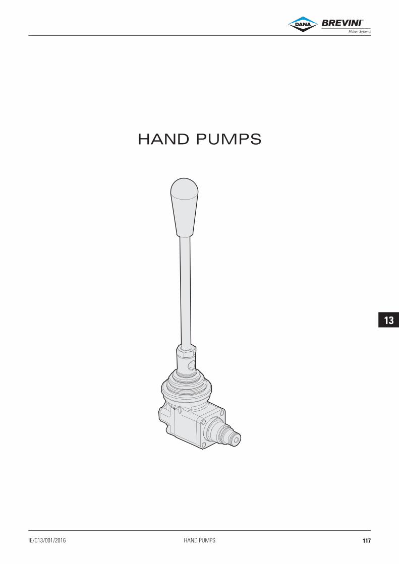
13
IE/C13/001/2016 HAND PUMPS
HAND PUMPS
®
117

13
CPM04
2
1
CPM 04 * 0 00 1
01
02
F (
daN
)
P(bar)
0
10
15
20
25
30
35
0 50 100 150 200 250 300 350
3/4
- 1
6 U
NF
1
2
23
24
42
27
3 2.
43 2.
23.3°22.7°
66.5
12.7
170.5
16.4
57.5
59 7.(5-6 Nm)
R12 5.
209
Mandata
In line pressureAspirazione
Suction line
max. 32 85.
4
10 12- Nm
16
IE/CPM04/002/2016HAND PUMPS
HAND PUMPS
HYDRAULIC SYMBOL
HYDRAULIC FEATURES
Max. working pressure CPM041 = 300 barCPM042 = 160 bar
Displacement CPM041 = 1 cc strokeCP0M42 = 2 cc stroke
Working Temperature -25°C ÷ 60°C
Max. Leakage (0 ÷ 5 drops/min) 0 ÷ 0.25 cm3/min
Hydraulic fluid DIN 51524 Mineral oils
Fluid viscosity 10 ÷ 500 mm2/s
Fluid temperature -25°C ÷ 75°C
Max. contamin. level class with filter ISO 4406:1999 - class 19/17/14
Weight 0.41 kg
Tightening torque 25 ÷ 30 Nm
Cavity (3/4 - 16 UNF) CD018006 (See section 17)
OPERATION FORCE ON THE LEVER
Fluid used: mineral based oil with viscosity 32 mm²/s at 40°C.
CPM = Hand pumpSeries
Size
Version
04 = 3/4 - 16 UNF
1 = Displacement 1 cc2 = Displacement 2 cc
1 = Serial No.
00 = No variants
0 = Standard positioning (90° to the valve axis) - See drawing
ORDERING CODE
With 200 mm lever
Variants
This hand pump handles emergencies manually in small systems.Available in 1cc/pump stroke and 1cc/pump stroke displacement versions.The lever body is in diecast aluminium. The cartridge is steel with tempered and ground steel ball check valves.
00012032 Spare seals kit
®
118

14
IE/C14/001/2016 VALVE HOUSINGS
VALVE HOUSINGS
®
119

14
1
2
M
E
Ø 6.5D
G
IL
F
C
C
H
3/4-16 UNF
NM
D
F
L
O
G
E
C
C
H
1
I
2
3/4-16 UNF
IE/MANIFOLDS/004/2016VALVE HOUSINGS
Valve housings
Code C D(mm)
E(mm)
F(mm)
G(mm)
H(mm)
I(mm)
L(mm)
M(mm)
N(mm)
O(mm) Material Cavity
17030532 3/8 BSP 50 50 16 32 35 51 22 9 30 34.5 Alluminium EN AW 2011 CD018006
V10500034 1/4 BSP 40 46 11 31 26 49 19 8 30 26
Code C D(mm)
E(mm)
F(mm)
G(mm)
H(mm)
I(mm)
L(mm)
M(mm) Material Cavity
F07100013 1/4 BSP 46 50 30,5 33 18 38 6 30Alluminio
EN AW 2011 CD018006M18400061 3/8 BSP 55 60 38 41,25 25 45 7,5 30
M18400071 1/2 BSP 60 60 35 41 6 48 6 40
®
120

14
IE/MANIFOLDS/004/2016
26
14,5
44
84
4
3/8
BS
P
60
3/4
-16
UN
F
3/8 BSP
8
3/8 BSP
30
30
60
15
3
2
1
Ø 6.5 No 2
3
2
1
30
7/8
- 1
4 U
NF
7.5
45
60
17.5
53
18
35 Ø 6.5 No 2
3/8 BSP
3/8 BSP
3/8
BS
P
35
70
VALVE HOUSINGS
Valve housings
Code Material Cavity
M10850319 Alluminium - EN AW 2011 CD019006
Code Material Cavity
M10850206 Alluminium - EN AW 2011 CD018005
®
121

14
VALVE HOUSINGS
®
122

IE/CAVITIES/006/2016
15
IE/C15/001/2016 CAVITIES
CAVITIES
®
123

IE/CAVITIES/006/2016
15
R78150114 R78150109 R78150111
20001900 20001700 20003800 20009400 20018000 20001900 20001700 20003800 20009400 20018000
20001700 20001900
CD018001CA012001 3/4 16UNF1/4 BSP
CD018005CD018003 3/4 16UNF3/4 16UNF
CD018009CD018006 3/4 16UNF3/4 16UNF
Ø 10 H7+0.015
0
Ø14 H7+0.018
0
30°
1.5
10.5
37
+0.1
5
-0
.05
30°
35.5
Min
.A
lesa
to
Min
. bore
d
9-0
.05
-0
.15
60°
1/4 BSP
7.2
5 m
in
11.7
5 m
ax
25 m
in
17.5
33.5
max
Max. Ø 6.5
1.6
1.6
Ø 0.05 A
A
30°
30°
30°
45°
15°
2.7
19.1
33.3
47.6
56
Ø 12.72 ±0.02
Ø 14.3 ±0.02
Ø15.9±0.02
Ø20.65 ±0.05
Ø27
R0.2
5
11.5
3/4" 16UNF
Max. Ø 11.5
9.5
min
17.5
ma
x
25.7
5 m
in
31.7
5 m
ax
40 m
in
46 m
ax
1.6
1.6
1.6
1.6
3.2
0.05 A
Ø 0.02 B-C-D
A
B
C
D
13
15°
1.6
1.6
3.2
1.6
A
Ø0.05 A
AØ0.05
B0.05
Ø0.05 A
B
41.3
3/4"/16UNF
25.7
5m
ax
33.3
Ø13 max
19
.1
2.5
±0.02Ø14.3
Ø27
±0.02
R0.2±0.05
30°
+0.1
0
+0.4
0
30°45°
120°
ma
x9
.5
ma
x17.5
Ø15.9
Ø20.6
31.7
5m
ax
2.7
15
25.7
Ø13 max
Ø30
Ø20.65 ±0.05
±0.03
Ø15.9
Ø14.3 ±0.03
31.7
515°
45°
30°
30°
60°
R0.25
9.7
7.6
min
19.8
min
13.6
max
24.3
max
3/4''-16UNF
1.6
1.6
1.6
0.05 X
0.05 Y
0.05 X
0.05 Y
0.05 J
0.05 X
X
Y
J
R0.2
Ø11.5 max
9.5
min
17.5
max
Ø12.7
15°
60°
45°
30°
Ø28
Ø20.6
19.5 1
7.5 13
2.5
29
±0.0
5
+0.05
0
+0.1
0
+0.4
0
±0.1
3/4''-16UNF
1.6
3.2
1.6
0.05 A
A
B
B
B
Ø0.05
Ø0.02 R0.2
Ø10.5 max
9.5
min
50 m
in
17.5
max
65.5
max
Ø12.7
Ø11.5
15°
45°
30°
30°
Ø26
Ø20.6
19.5
41
66.5
17.5 13
2.5 ±0
.05
+0.05
0
+0.1
0
+0.1
0
+0.2
0
+0.4
0
±0.1
±0.1
3/4''-16UNF
1.6
3.2
1.6
0.05 A
A
B
B
B
Ø0.05
Ø0.02
60°
CAVITIES
Cavities
Plugs compatibility: Plugs compatibility:
Plugs compatibility: Plugs compatibility:
Plugs compatibility: Plugs compatibility:
®
124

IE/CAVITIES/006/2016
15
R78200A19 20001700 20001900 R78150100
20018000 20001700 20001900 20003800 20009400
20001900 20001700 20003800 20009400 20018000 20018000 20001700 20001900 20003800 20009400
CD018013CD018012 3/4 16UNF3/4 16UNF
CD018015CD018014 3/4 16UNF3/4 16UNF
CD019006CD018016 7/8 14UNF3/4 16UNF
1.6
1.6
3.2
120°
45°
30°
19
.5
15°
30
2.5
Ø15.87
13
3/4'' 16UNF
9.5
m
in
Ø20.6
17
.5 m
ax
Ø 28
Ø14 max
R0.2
±0.05
+0.05
0
+0.4
0
+0.1
0
0 -0.2
0 -0.1
0.05 B
A
B
A
A
Ø0.05
Ø0.05
R0.2
±0.0
5
+0.1
0
+0.05
0
+0.05
0
0.05 A
A
B
B
B
B
Ø0.05
Ø0.02
Ø0.05
3/4" 16UNF
Ø26
Ø 9 max
R 0.4
Ø 14.5
Ø 15.8
15°
Ø20.6
+0.2
0
+0.2
0
+0.4
0
62.5
Min
.A
lesato
Min
. bore
d
67.5
17.5
2.5
9.5
min
34.5
min
56 m
in
17 m
ax
42.5
max
64 m
ax
42.5
12
65°
45°
70°
3.2
1.6
1.6
1.6
±0.1
1.6
1.6
0.8
3.2
0.015
17
.5
19
.53/4'' 16UNF
R0.5 max
+0.05
0Ø12.7
+0.10
13
Ø20.6
Ø28
R0.2 ±0.05
0 -0.1
+0.018
0
0.05 B
A
B
A
A
Ø0.05
Ø0.05
Ø 8 max
Ø 12 H7
+0.2
0
+0.4
0
52.2
Min
.A
lesato
Min
. bore
d
53.5
2.5
9.5
min
27 m
in
17.5
max
34 m
ax
34
45°
15°
30°
30°
30°±
0.1
2.8
23.1
39.6
47.6
Ø24
Ø17.5
Ø15.9
Ø30
max Ø 14.5
R 0.25
16
7/8" 14UNF
21.5
max.
30.7
min
.
37.7
max.1.6
3.2
1.6
1.6
0.05 A
B
C
A
B-CØ0.02
15°
30°
30°
60°
45°
±0.05
±0.02
±0.02
R0.2
±0.0
5
+0.1
0
+0.05
0
0.05 A
A
B
B
B
Ø0.05
Ø0.02
3/4" 16UNF
Ø26
Ø 11.5 max
Ø 12.7
15°Ø20.6
+0.4
02.5
9.5
min
17.5
max3
0.5 19.5
13
17.5 6
0°
30°
45°
3.2
1.6
1.6
±0.1 ±
0.1
1.6
1.6
0.8
3.2
3.2
0.015
29 19
.5
32
.4
+0.05
0Ø12.7
Ø20.6
Ø28
R0.2 ±0.05
0 -0.1
0 -0.2
+0.018
0
0.05 B
A
B
A
A
A
Ø0.05
Ø0.05
Ø 0.1
Ø 12 H7
+0.4
0
+0.1
0
2.5
9.5
min
27 m
in
17.5
max
32 m
ax
Ø12.4
79
45°
15°
30°
30°
±0.1
±0.1
==
17
.5
3/4'' 16UNF
13
120°
120°±0.05
CAVITIES
Cavities
Plugs compatibility: Plugs compatibility:
Plugs compatibility: Plugs compatibility:
Plugs compatibility: Plugs compatibility:
®
125

IE/CAVITIES/006/2016
15
R78100033
CG001002
CD019007
1/8 BSP
7/8 14UNF
CA007001
CG003004
M8X1
3/8 BSP
CN019002 M10X1
Ø24
Ø15.9
Ø30
max Ø 14.5
3.2
1.6
1.6
R0.2±0.05
0.05 A
33.3
23.7
1
60°
30°
16
12.5
min
23.5
max
7/8'' 14UNF
B
A
B
B
Ø0.05
Ø0.05+
0.4
0
+0.4
0+
0.2
0
2.5
15°45°
±0.05
±0.02
3/8 BSP
1x4
5°
15°
32
21
.5
Ø 14 H8
Ø 13 max
20
Ø 25
+0.027
0
+0.5
0 0
-0.1
+0.2
0
0.1 B
B
A
AØ0.05
1.6
1.6
(Ø 7.8 Preforo/Prefinish)
R 0.2 max
M 10 x 1
Ø 4.5
Ø 4 max
31
.5
27
.5 m
ax
22
.5 m
in
0.7
x 4
5°
12
.5
Ø 8 H8
10
28
30°
25 M
in.
Ale
sa
to
Min
. bore
d
0.02
0.03
A
B
B
A
A
0.01
Ø0.05
+0.5
0
+0.022
0
1.6
1.6
1.6
1.6
±0.1
±0.1
±0.05
2,5
0
+0
,4
33
,3
23
,70
+0,4
10
+0,2
30°
R0,2±0,05
16
24 ±0,05
30
120°
12 max
46
13
45°
7/8''-14UNF
120°
12
,5m
in 23
,5m
ax
15°
R0,2
15,9 ±0,02
1.6
1.6
3.2
0.05 A
0.05 B
0.05 A
B
A
R78100033
CD019011 7/8 14UNF
0.5
x4
5°
30
17
19
8.5
min
12
max
23
.5 m
in
28
.5 m
ax
Ø 8 H8
Ø 8.8
Ø 5 max
R 0
.2 m
ax
Ø 17
G1/8"-H
+0.022
0
0
-0.1
0
-0.2
+0.2
0
+0.2
0
0.05
0.05
A
A
A
AØ0.05
1.6
1.6
1.6
30°
Ø7 0
+0 1.
45°
4 5.
0
+0
1.
11
2.0
+0
1.
Ø .6 5 H8+0 022.
0
30°
30°
0.5
-
0 0 1.
Ø9 H8+0 022.
0
R0.2 max.
16.2
min
.
20.5
max.
7 m
in.
10.7
max.
Ø11
M8X1
Ø4 max
9.5
min
1.6
1.6
0.05 A
0.05 A
A
CAVITIES
Cavities
Plugs compatibility:
Plugs compatibility:
Plugs compatibility:
Plugs compatibility:
Plugs compatibility:
Plugs compatibility:
®
126

IE/CAVITIES/006/2016
15
2.5
14.5
Ø18
M14x1.5
29
8 m
in
M10x1
39
18 m
in
28 m
ax
15°
45°
Ø15.8
Ø 3.5 max
R0.20
-0.1
A
A
A
Ø0.03
Ø0.03
+0.2
0
+0.2
0
+0.1
0
1.6
1.6
1.6
M16X1
20019700 20021300
20006100 20001600
R78260072
CN033001 M15X1
CN037003CN036001 M16X1.5.
CN041009 M18X1.5CN037004 M16X1.5
CN032005 M14X1.59
Ø23
Ø 17.3
Ø15
2.5
14
.8
32
R 0.2
R 0.4
0.5
x4
5°
M16x1
Ø9
6.5
min
14
ma
x
10
23
.8 m
in
M10x1
Ø8.5 max
120°
45°
15°
0
-0.1
0
-0.1
0.05
0.05
B
C
A
C
B
AØ0.05
+0.1
0
1.6
1.6
3.2
±0.0
5
0.05 A
Ø13
Ø12 max
Ø14.5
3.7
15
min
28
ma
x
Ø18
25°45°
45°
29
37
M16x1.5
16
.5
Ø29
R0.2
A
A
A
Ø0.02
Ø0.05
+0.2
0
+0.05
+0.01
0
-0.1
3.2
1.6
1.6
±0.1
±0.1
±0.0
5
1.6
Ø16.5
M16x1.5
Ø12.5 H8
30°
30°
23
1.5
9.5
Ø5 max
39
.5
1.2
5
16
.5 m
in
21
.5 m
ax
31
min
39
ma
x
A
A
A
Ø0.03
Ø0.03
+0.027
0
+0.03
0
1.6
1.6
1.6
1.6
±0.1
±0
.2
±0.1
45°
0.05 A
Ø13.5
Ø14
Ø18.4
26
39
.5
0.7
5x4
5°
2.5
16
1
Ø16.5
13
8.2
5 m
in
15
.75
ma
x
M18x1.5
Ø34
R0.7-0.8
30°
A
A
A
Ø0.02
Ø0.05
+0.2
0
+0.2
0
+0.1
0
+0.05
+0.01
+0.2
0
+0.05
0
3.2
1.6
1.6
±0.1
Max. Ø 7 mm
Ø23
Ø16
Ø8
M15 x 1
4
13
19
0.8
29
.5
30°
0.6
x4
5°
10
min
18
ma
x
R 0
.5
Ø14 foro per filettatura
threaded hole
0.03
0.03
A
A
A
A
A
Ø0.05
Ø0.05
+0.2
0
+0.2
0
+0.2
0
+0.3
0
+0.1
0
+0.07
+0.02
1.6
1.6
1.6
3.2
±0.1
CAVITIES
Cavities
Plugs compatibility:
Plugs compatibility: Plugs compatibility:
Plugs compatibility: Plugs compatibility:
Plugs compatibility:
®
127

IE/CAVITIES/006/2016
15 R78050014 R78400A17
R78300564
CN047002
CN044003
M22X1.5
M20X1.5
CN051001
CN047003
M24X2
M22X1.5
CN059001 M27X1.5
3
14.5
28
60°
30°
Ø15 H8
Ø21.4
Ø25
15°
45°
M20x1.5
max Ø 14
11
10 m
in
16 m
ax
R 0.2
0.1 A
A
B
C
B-C0.05+0.027
0
3.2
1.6
±0.1
±0.2
R78300562
CN044001 M20X1.5
Ø23.8
2.4
30.6
40
Max Ø16.5
Ø17.5 H8
Ø34
15°
45°
30°
20
R 0.2
60°
13.2
5 m
in
28.2
5 m
ax
M22x1.5
0.05 A
B
A
BØ0.02
+0.4
0
+0.5
0
+0.4
0
+0.1
0
+0.027
0
3.2
1.6
1.6
33
14
Ø22 H9
56
min
.
11
M24x2
19 m
in
32 m
ax
13
Ø22.3
1x45°
R0.5
Max. Ø13
0.05 A
A
B
BØ0.02
+0.052
0
+0.2
0
2.5
2.5
Ø33.5
Ø28
30°
45° Ø25.5
Ø12 max
0.6
37.5
17 m
in
36.5
max19
M27x1.5
6
A
AØ0.03
+0.04
-0.01
+0.2
0
+0.1
5
0
3.2
1.6
1.6
1.6
2.4
49.5
60.5
28
Ø17 H8
Ø19 H8
Ø34
Ø23.8
30°
30°
15°
45°
R 0
.2
17
M22x1.5
17.5
min
28 m
ax
39 m
in
49.5
max
Max. Ø 10.5
0.05 A
A
B
C
B-CØ0.02
+0.4
0
+0.4
0
+0.1
0
+0.027
0
+0.033
0
0 -0.1
3.2
1.6
1.6
1.6
0.05+0Ø 21
77tr
atto
min
ales
ato
min
bore
d
0.03
0.15
1.25
1.6
A
1.25
0.03 A
3.2
A
c3.2
1.25
A
0.1
1
0.4
+
0.01
0.01
047
0
-
20°
+
47m
ax
20°
0.05
+
R
20°M x 1.520
+
Ø 11 max.
69m
in
max.
Ø 32
±0.0
5
+
+
45°
0
0.1
4
26m
in
0.1
-0.2
Ø20.4
12m
in
0.04
Ø 17.5 + 0.01+ 0.05
Ø 16.5 +
1319
78
19m
ax
77.5
max
(preforo/prefinsh) Ø18.5
CAVITIES
Cavities
Plugs compatibility:
Plugs compatibility:
Plugs compatibility:
Plugs compatibility:
Plugs compatibility:
Plugs compatibility:
®
128

IE/CAVITIES/006/2016
15
R78400568
CN070001 M33X2
45
0
+0
,2
22
30,75 H8 0
+0,04
77
31
15
17
M33x2
43
27
MAX. 20
33
1x45°
R0,5
1
30°
1.6
1.6
0.01 A
A
B
Ø 0.02 B
CAVITIES
Cavities
Plugs compatibility:
Plugs compatibility: Plugs compatibility:
Plugs compatibility: Plugs compatibility:
Plugs compatibility:
®
129

IE/CAVITIES/006/2016
15
CAVITIES
®
130

16
IE/C16/001/2016 STANDARD PLUGS
STANDARD PLUGS
®
131

16
20001600M18X1.5
200017003/4 16UNF
200180003/4 16UNF
200019003/4 16UNF
200038003/4 16UNF
20006100M16X1.5
200094003/4 16UNF
20019700M15X1
20021300M15X1
R78050014M22X1.5
R781501093/4 16UNF
R781501113/4 16UNF
R781501143/4 16UNF
R78200A193/4 16UNF
R78260072M16x1.5
22
1
22
1
X
22
1
X
22
1
22
1
22
1
22
1
X
22
1
22
1
22
1
22
1
2 4
13
2 4
13
2 4
13
10
.5
16
.5
1/4 BSP
3/4-16 UNF
24
25 - 30 Nm
1-2
X
M16 x 1.5
19
28 - 32 Nm
14
.5
19
1-2
M15 x1
17
16 - 19 Nm
11
4
20
1-2Ø 15.8
3/4-16UNF
24
28 - 32 Nm
1
2
26
33.5
3/4-16 UNF
10
.516
.5
24
25 - 30 Nm
1-2
2733
.5
Ø 12.7
3/4-16 UNF
24
25 - 30 Nm
1
2
Ø 12.7
12
3/4-16 UNF
1/4 BSP24
25 - 30 Nm
27 33
.51
X
2
Ø 12.7
12
3/4-16 UNF
1/4 BSP24
25 - 30 Nm
27
33
.5
1
X
2
2
1Ø 12 1
M15 x 1
17
16 - 19 Nm
20
26
Ø 15.9
3/4-16 UNF
24
25 - 30 Nm
28 36
2
1
Ø 12.7
Ø 14.3
Ø 15.9
53.8 60.3
3/4-16UNF
24
28 - 32 Nm
1
3
2
4
Ø 12.7
Ø 14.3
53
.8 60.3
3/4-16UNF
24
28 - 32 Nm
1
3
2
4
Ø 12.7
Ø 15.9
53.8 60.3
3/4-16UNF
24
28 - 32 Nm
1
3
2
4
M18 x 1.5
Ø 14
24
28 - 32 Nm
1
2 24
.5 34
.5
23
116 - 18 Nm
Ø16.5
2
13.5
35.5
Ø10
M16x1.5
Ø4.5
Ch. 6
1
2
3
R781501003/4 16UNF
2
1 3
24
30 - 40 Nm
36.9
64
Ø 26
M22x1.5
Ø 19
Ø 20
IE/PLUG/004/2015STANDARD PLUGS
Standard plugs ®
132

16
IE/PLUG/004/2015
R78300564M24X2
R78400568M33X2
R78400A17M22X1.5
R781000337/8” 14UNF
.. ..
22
1
22
1
Ø 30.8
M33 x 2
M8
36
80 - 90 Nm
46
.5
56
.5
2
1
2
1Ø 17.5
M22x1.5
27
30 - 40 Nm
38
45
.5
22
1
2
1
Ø 22
M8
M24 x 2
27
60 - 70 Nm
35
.3
40
.3
R78300562M20X1.5
2
1
Ø 15
M20 x 1.5
24
30 - 35 Nm
28 3
4
22
1
2
1
1
2
Ø 27
32
6
38
7/8" 14UNF
35 - 40 Nm
Ch. 10
STANDARD PLUGS
Standard plugs ®
133

16
STANDARD PLUGS
®
134

17
IE/C17/001/2016 COILS
COILS
®
135

17
17
21.5
20.5
Ø13.25
30 38.6
42
12
28ISO 4400
(DIN 43650)
28
30 38.6
1 min
9.5
60
04
2
20
.5
16.7
5
41
37
4
39
27
261
.5
30
19
,7
24,3
IE/COILS/004/2014COILS
CoilsC30 - COILS 18W
(1) Ambient temperature 25 °C - (2) Ambient temperature 20 °C(3) The european low voltage directive is applied to electronical equipments used at a nominal voltages
between 50 and 1000 VAC or 75 and 1500 VDC. In conformity with the low directive each part of the manifold or the subplate on which the valve is mounted should be connected to a protective earth with a resistence less than 0.1 ohms.
Standard (Hirschmann ISO 4400 DIN43650)
With wires (variant FK)
DEUTSCH and bidirectional integrated diode (variant CX)
(1) Ambient temperature 25 °C - (2) Ambient temperature 20 °C
(1) Ambient temperature 25 °C - (2) Ambient temperature 20 °C
Type of protection IP 65Number of cycle 18000/hSupply tolerance ±10%Ambient temperature -30°C ÷ 60°C
Coil Max windingtemperature (1)
Ratedpower
Resistance±7% (2)
SparecodeCode Voltage
L 12 VDC 110 °C 18 W 7.7 M14000001M 24 VDC 110 °C 18 W 31 M14000002N 48 VDC 110 °C 18 W 116 M140000032 21.6 VDC 110 °C 18 W 27 M14000009Z 102 VDC (3) 110 °C 18 W 578 M14000006X 205 VDC (3) 110 °C 18 W 2627 M14000007A 24 VAC/50 Hz 100 °C 35 VA 5.3 M14001002J 115 VAC/50 Hz (3) 100 °C 35 VA 108 M14001004I 230 VAC/50 Hz (3) 100 °C 35 VA 438 M14001005F 24 VAC/60 Hz 100 °C 35 VA 3.8 M14001012C 110 VAC/60 Hz (3) 100 °C 35 VA 92 M14001014D 220 VAC/60 Hz (3) 100 °C 35 VA 375 M14001015
Coil Max windingtemperature (1)
Ratedpower
Resistance±7% (2)
SparecodeCode Voltage
L 12 VDC 110 °C 18 W 7.7 M14000101M 24 VDC 110 °C 18 W 31 M14000102
Coil Max windingtemperature (1)
Ratedpower
Resistance±7% (2)
SparecodeCode Voltage
L 12 VDC 110 °C 18 W 7.7 M14760001M 24 VDC 110 °C 18 W 31 M14760002
Duty cycle 100% EDInsulation class wire HWeight 0.141 kg
®
136

17
IE/COILS/004/2014
47.8
19.8
24.3
23.5
Ø13.2
36 38.5
12
28 ISO 4400
(DIN 43650)
28
36 38.5
5
600
47.8
23.5
9.5
1 min21.5
36 38.5
60.8
47.8
23.5
19.1
47.8
23.5
36
67.5
38.5
COILS
CoilsC36 - COILS 22W
(1) Ambient temperature 25 °C - (2) Ambient temperature 20 °C(3) The european low voltage directive is applied to electronical equipments used at a nominal voltages
between 50 and 1000 VAC or 75 and 1500 VDC. In conformity with the low directive each part of the manifold or the subplate on which the valve is mounted should be connected to a protective earth with a resistence less than 0.1 ohms.
Standard (Hirschmann ISO 4400 DIN43650)
With wires (variant FK)
AMP Junior (variant AJ)
(1) Ambient temperature 25 °C - (2) Ambient temperature 20 °C
(1) Ambient temperature 25 °C - (2) Ambient temperature 20 °C
Type of protection IP 65Number of cycle 18000/hSupply tolerance ±10%Ambient temperature -30°C ÷ 60°C
Duty cycle 100% EDInsulation class wire HWeight 0.2 kg
Coil Max windingtemperature (1)
Ratedpower
Resistance±7% (2)
SparecodeCode Voltage
L 12 VDC 115 °C 22 W 6.3 M140400014 14 VDC 115 °C 22 W 8.9 M14040009M 24 VDC 115 °C 22 W 25.6 M14040002V 28 VDC 115 °C 22 W 32.8 M14040008N 48 VDC 115 °C 22 W 102 M140400032 21.6 VDC 115 °C 22 W 20.2 M14040000Z 102 VDC (3) 115 °C 22 W 467.85 M14040006X 205 VDC (3) 115 °C 22 W 1954 M14040007
Coil Max windingtemperature (1)
Ratedpower
Resistance±7% (2)
SparecodeCode Voltage
L 12 VDC 115 °C 22 W 6.3 M140401014 14 VDC 115 °C 22 W 8.9 M14040109M 24 VDC 115 °C 22 W 25.6 M14040102V 28 VDC 115 °C 22 W 32.8 M14040108
Coil Max windingtemperature (1)
Ratedpower
Resistance±7% (2)
SparecodeCode Voltage
L 12 VDC 115 °C 22 W 6.3 M14730001M 24 VDC 115 °C 22 W 25.6 M14730002
Deutsch + bidirectional diode - DT04-2P (connection D / variant CX)
(1) Ambient temperature 25 °C - (2) Ambient temperature 20 °C
Coil Max windingtemperature (1)
Ratedpower
Resistance±7% (2)
SparecodeCode Voltage
L 12 VDC 115 °C 22 W 6.3 M140402014 14 VDC 115 °C 22 W 8.9 M14040209M 24 VDC 115 °C 22 W 25.6 M14040202V 28 VDC 115 °C 22 W 32.8 M14040208
®
137

17
18
12
46
Ø14.1 min
36 39
2828
ISO 4400
(DIN 43650)
18
46
59
17
36 39
19.9
18
65.9
36 38.5
18
16.5
46
5
F / F
L
I / L
D
= 2
50
= 1
30
36 39
IE/COILS/004/2014COILS
CoilsA09 - COILS 27W
(1) Ambient temperature 25 °C - (2) Ambient temperature 20 °C(3) The european low voltage directive is applied to electronical equipments used at a nominal voltages
between 50 and 1000 VAC or 75 and 1500 VDC. In conformity with the low directive each part of the manifold or the subplate on which the valve is mounted should be connected to a protective earth with a resistence less than 0.1 ohms.
Hirschmann ISO 4400 DIN43650 (connection H)
With wires and integrated bidirectional diode (connection F-I / variants FL-LD)
AMP Junior (connection A / variant AJ)
(1) Ambient temperature 25 °C - (2) Ambient temperature 20 °C
(1) Ambient temperature 25 °C - (2) Ambient temperature 20 °C
Type of protection IP 65Number of cycle 18000/hSupply tolerance ±10%Ambient temperature -30°C ÷ 50°C
Duty cycle 100% EDInsulation class wire HWeight 0.215 kg
Deutsch + bidirectional diode - DT04-2P (connection D / variant CX)
(1) Ambient temperature 25 °C - (2) Ambient temperature 20 °C
Coil Max windingtemperature (1)
Ratedpower
Resistance±7% (2)
SparecodeCode Voltage
L 12 VDC 123 °C 27 W 5.3 M14310001M 24 VDC 123 °C 27 W 21.3 M14310002N 48 VDC 123 °C 27 W 85.3 M14310003Z 102 VDC (3) 123 °C 27 W 392 M14310008P 110 VDC (3) 123 °C 27 W 448 M14310005X 205 VDC (3) 123 °C 27 W 1577 M14310009
Bobina Wires(mm)
Max windingtemperature (1)
Ratedpower
Resistance±7% (2)
SparecodeCodice Tensione
L 12 VDC F = 250 123 °C 27 W 5.3 M14070011M 24 VDC F = 250 123 °C 27 W 21.3 M14070012L 12 VDC I = 130 123 °C 27 W 5.3 M14330001M 24 VDC I = 130 123 °C 27 W 21.3 M14330002
Coil Max windingtemperature (1)
Ratedpower
Resistance±7% (2)
SparecodeCode Voltage
L 12 VDC 123 °C 27 W 5.3 M14320001M 24 VDC 123 °C 27 W 21.3 M14320002
Coil Max windingtemperature (1)
Ratedpower
Resistance±7% (2)
SparecodeCode Voltage
L 12 VDC 123 °C 27 W 5.3 M14340001M 24 VDC 123 °C 27 W 21.3 M14340002
®
138

17
IE/COILS/004/2014
ISO 4400
(DIN 43650)
Ø19
45.5 61.01
45
.5
33
.71
2
30 30
ISO 4400
(DIN 43650)
51
19 28
Ø19.2
Ø 37
28
27
.1
12
COILS
CoilsA12 - COILS 23W
(1) Ambient temperature 25 °C - (2) Ambient temperature 20 °C
Standard (Hirschmann ISO 4400 DIN43650)
Type of protection IP 65Number of cycle 18000/hSupply tolerance ±10%Ambient temperature -30°C ÷ 60°C
Duty cycle 100% EDInsulation class wire HWeight 0.22 kg
Coil Max windingtemperature (1)
Ratedpower
Resistance±5% (2)
SparecodeCode Voltage
F 12 VDC 115 °C 23 W 5.3 M14850001G 24 VDC 115 °C 23 W 25.3 M14850002
D12 - COILS 30W
(1) Ambient temperature 25 °C - (2) Ambient temperature 20 °C
Standard (Hirschmann ISO 4400 DIN43650)
Type of protection IP 65Number of cycle 18000/hSupply tolerance ±10%Ambient temperature -30°C ÷ 60°C
Duty cycle 100% EDInsulation class wire HWeight 0.2 kg
Coil Max windingtemperature (1)
Ratedpower
Resistance±7% (2)
SparecodeCode Voltage
L 12 VDC 108 °C 30 W 4.7 M14100010M 24 VDC 108 °C 30 W 18.8 M14100011
®
139

17
COILS
®
140

18
IE/C18/001/2016 CONNECTORS
CONNECTORS
®
141

18
81.5
Ø 2 ÷ 3 mm
20
23
.5
Ø 6÷8 mm (PG09)
Ø 8÷10 mm (PG11)
IP65
Ø 4÷7 mm19
IP67
M3
4.5
42
28.5 29.5
Ø 6÷8 mm (PG09)
Ø 8÷10 mm (PG11)
34.54.5
M3
42
29.5
Ø 6÷8 mm (PG09)
4.5
M3
32
62
29.5
Ø 4÷7 mm
1
2
1
2
1
2
1
2
IE/CONN/003/2015CONNECTORS
CONNECTORS FOR CONTROL VALVES IN ACCORDANCE WITH DIN 43650 / ISO 4400
AMP JUNIOR CONNECTORS
Connector Type Cable section Pin conctatmax current Code
AMP Junior connector Timer 2 conctat Black color 0,5 ÷ 1,5 mm2 10A RKRC0808000
Connector Protection level Type Cable gland Code
Standard IP65
Black color PG09 V86 05 0002Grey color PG09 V86 05 0004Black color PG11 V86 05 0006Grey color PG11 V86 05 0008
Lens cover with pilot light (1) IP65
12 VAC/VDC PG09 V86 10 001824 VAC/VDC PG09 V86 10 0012115 VAC/VDC PG09 V86 10 0020230 VAC/VDC PG09 V86 10 0022
Connector Protection level Type Cable gland Code
With rectifier (1)Inlet voltage 12÷230 VACOutlet voltage 9÷205 VDC
IP65Black color PG09 V86 20 0002
Grey color PG09 V86 20 0004
Lens cover with pilot light and rectifier (1)Inlet voltage 12÷230 VACOutlet voltage 9÷205 VDC
IP65
12 VAC PG09 V86 25 001824 VAC PG09 V86 25 001948 VAC PG09 V86 25 0020115 VAC PG09 V86 25 0021230 VAC PG09 V86 25 0022
Connector Protection level Type Cable gland Code
With protection level IP67 IP67Black color — V86 28 0001Grey color — V86 28 0002
Seal
Cable gland
Seal
Seal
Cable gland
Description IP65 IP67
AC rated voltageDC rated voltage
Max. 250 VMax. 300 V
Max. 250 VMax. 300 V
Pin conctat nominal currentPin conctat max. current
10A 16A
10A 16A
Max. section cable 1.5 mm² 1.5 mm²
Cable gland PG09 - M16x1,5Cable gland PG11 - G 1/2” - M20x1,5
Ø cable 6 ÷ 8 mmØ cable 8 ÷ 10 mm
Ø cable 4 ÷ 7 mm—
Protection levelInsulation classOperating temperature
IP65 EN60529VDE 0110-1/89-40°C ÷ 90 C°
IP67 EN60529VDE 0110-1/89-20°C ÷ 80 C°
The degrees of protection indicate is guaranteed only if the connectors were properly mounted with his original seals.
Electrical features of connectors
Screw tightening torque: 0.60 Nm
Screw tightening torque: 0.60 Nm
(1) do not use for proportional versions
(1) do not use for proportional versions
Standard Bipolar led Rectifier andVDR protection
Bipolar led, rectifier andVDR protection
Electrical circuits
Connectors ®
142

Note ®
143

Note ®
144


®
Dana Motion Systems Italia S.r.l.Fluid Power Division
Sede operativa: Via Giulio Natta 1, 42124 Reggio Emilia - Italy Tel: +39.0522.270711 - Fax: +39.0522.505856
Sede legale: Via Luciano Brevini 1/A, 42124 Reggio Emilia - Italy Tel: +39.0522.9281 - Fax: +39.0522.928300
www.dana.com/brevini - [email protected]
Code DOC00044 - Rev. 11