case error codes
TRANSCRIPT

7/23/2019 Case Error Codes
http://slidepdf.com/reader/full/case-error-codes 1/140
Section 55Chapter 9
INSTRUMENT CLUSTER (ICU2)TG SERIES P.I.N. JAW 137300 AND AFTER
Programming and Fault Codes
Special Note: Only Fault Codes which have changed due to the Later Version ICU (ICU2) are included inthis section. If the tractor has the Later Version ICU, use the schematic foldouts in this section with the
early version fault code troubleshooting.
7/23/2019 Case Error Codes
http://slidepdf.com/reader/full/case-error-codes 2/140
SECTION 55 - INSTRUMENT CLUSTER (ICU2) - CHAPTER 9
9-2
TABLE OF CONTENTS
INSTRUMENT CLUSTER (ICU2) ......................................................................................................................... 9-4
Warning/Fault Displays ......................................................................................................................................... 9-6
Critical Warning Displays - Level 1 ................................................................................................................... 9-6Non-Critical Displays - Level 2 .......................................................................................................................... 9-7
Deluxe Monitor Display (If Equipped) ............................................................................................................. 9-11
INSTRUMENTATION PROGRAMMING ............................................................................................................ 9-12
General Information ........................................................................................................................................ 9-12Operation Setup .............................................................................................................................................. 9-12
RADAR CALIBRATION .................................................................................................................................. 9-16Controller Configuration .................................................................................................................................. 9-19
Configuration/Calibration Mode ..................................................................................................................... 9-20
FAULT CODE RETRIEVAL ................................................................................................................................ 9-24
PASSIVE TERMINATOR BENCH TEST ............................................................................................................ 9-26
SYMPTOM BASED FAULTS - NO FAULT CODES ........................................................................................... 9-27
STANDARD INSTRUMENTATION CONTROLLER FAULT CODES ................................................................ 9-31
ARMREST CONTROLLER CALIBRATION ....................................................................................................... 9-52General Information ........................................................................................................................................ 9-52
Entering Armrest Calibration ........................................................................................................................... 9-53Hitch Menu ...................................................................................................................................................... 9-53
Throttle Menu .................................................................................................................................................. 9-55
Remote Valve Menu ....................................................................................................................................... 9-55ARM MFD ....................................................................................................................................................... 9-58
ARM TRANS ................................................................................................................................................... 9-58View Menu ...................................................................................................................................................... 9-59
Exit Calibration ................................................................................................................................................ 9-60
ARMREST CONTROLLER FAULT CODES ...................................................................................................... 9-61
TRANSMISSION CONTROLLER CONFIGURATION AND CALIBRATION ...................................................... 9-62
Important General Information ........................................................................................................................ 9-62When Calibration is Required ......................................................................................................................... 9-62
To access these menus: ............................................................................................................................... 9-63Trans View Mode ............................................................................................................................................ 9-64
Trans Setup Mode .......................................................................................................................................... 9-71
Clutch Calibration Procedure .......................................................................................................................... 9-72Calibration Error Messages ............................................................................................................................ 9-77
Gear Default Mode .......................................................................................................................................... 9-77
TRANSMISSION CONTROLLER FAULT CODES ............................................................................................ 9-90
7/23/2019 Case Error Codes
http://slidepdf.com/reader/full/case-error-codes 3/140
SECTION 55 - INSTRUMENT CLUSTER (LATER VERSION) - CHAPTER 9
9-3
REMOTE HYDRAULICS CONTROLLER CALIBRATION ................................................................................. 9-94
Requirements For Calibration ......................................................................................................................... 9-94Aux Set Main Menu ......................................................................................................................................... 9-94
Aux View Menu ............................................................................................................................................... 9-95Aux Adjust Menu ............................................................................................................................................. 9-97
Aux Setup Menu ............................................................................................................................................. 9-98
Aux Cal Menu ................................................................................................................................................. 9-99Calibration Process ....................................................................................................................................... 9-99
If Equipped with MegaFlow ......................................................................................................................... 9-100
REMOTE (AUX) CONTROLLER FAULT CODES ............................................................................................ 9-102
HITCH CONTROLLER CALIBRATION ............................................................................................................ 9-104
Setup Process ............................................................................................................................................... 9-104Requirements For Calibration ..................................................................................................................... 9-104
Hitch Setup Main Menu ............................................................................................................................... 9-104
Hitch Calibration Menu .................................................................................................................................. 9-105
Hitch Setting Menu ........................................................................................................................................ 9-110Hitch View Menu ........................................................................................................................................... 9-112
HITCH CONTROLLER FAULT CODES ........................................................................................................... 9-113
PTO CONTROLLER CONFIGURATION ......................................................................................................... 9-116General Information ...................................................................................................................................... 9-116
PTO Main Menu ............................................................................................................................................ 9-116PTO Speed Menu ......................................................................................................................................... 9-117
View Menu .................................................................................................................................................... 9-117
SYMPTOM BASED FAULTS - NO FAULT CODES ......................................................................................... 9-119
PTO CONTROLLER FAULT CODES .............................................................................................................. 9-121
SCHEMATIC FOLDOUTS ................................................................................................................................ 9-125
Data Bus sections 12 through 18 .................................................................................................................. 9-125Instrument Cluster ......................................................................................................................................... 9-127Transmission ................................................................................................................................................. 9-129
Transmission Control System ....................................................................................................................... 9-131PTO Controller System ................................................................................................................................. 9-133
Hitch Control System (EDC) ......................................................................................................................... 9-135Auxiliary Control System ............................................................................................................................... 9-137
Seat ............................................................................................................................................................... 9-13
7/23/2019 Case Error Codes
http://slidepdf.com/reader/full/case-error-codes 4/140
9-4
Template Name: OML_2_col Rac 0-00000Template Date: 2001_03_06
SECTION 55 - INSTRUMENT CLUSTER (ICU2) - CHAPTER 9
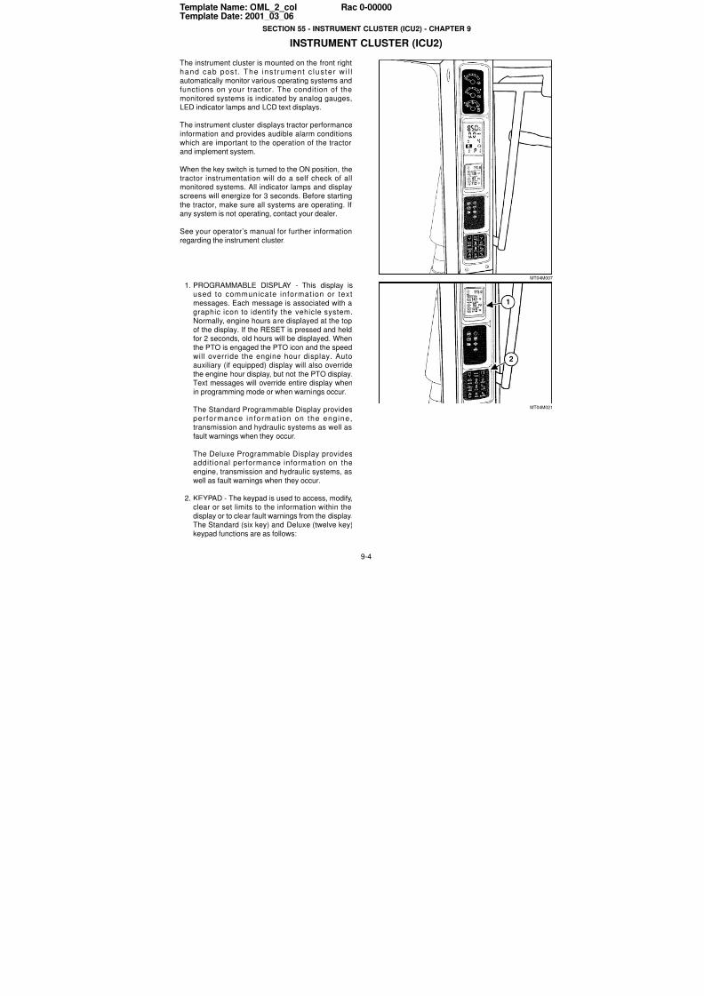
INSTRUMENT CLUSTER (ICU2)
The instrument cluster is mounted on the front right
hand cab pos t . The ins t rument c lus te r w i l l
automatically monitor various operating systems andfunctions on your tractor. The condition of the
monitored systems is indicated by analog gauges,LED indicator lamps and LCD text displays.
The instrument cluster displays tractor performance
information and provides audible alarm conditions
which are important to the operation of the tractorand implement system.
When the key switch is turned to the ON position, the
tractor instrumentation will do a self check of allmonitored systems. All indicator lamps and display
screens will energize for 3 seconds. Before starting
the tractor, make sure all systems are operating. Ifany system is not operating, contact your dealer.
See your operator’s manual for further information
regarding the instrument cluster.
1. PROGRAMMABLE DISPLAY - This display isused to communicate informat ion or text
messages. Each message is associated with a
graphic icon to identify the vehicle system.Normally, engine hours are displayed at the top
of the display. If the RESET is pressed and held
for 2 seconds, old hours will be displayed. Whenthe PTO is engaged the PTO icon and the speed
will override the engine hour display. Autoauxiliary (if equipped) display will also override
the engine hour display, but not the PTO display.Text messages will override entire display when
in programming mode or when warnings occur.
The Standard Programmable Display provides
per formance in format ion on the engine,transmission and hydraulic systems as well as
fault warnings when they occur.
The Deluxe Programmable Display providesaddit ional performance information on the
engine, transmission and hydraulic systems, as
well as fault warnings when they occur.
2. KEYPAD - The keypad is used to access, modify,clear or set limits to the information within the
display or to clear fault warnings from the display.The Standard (six key) and Deluxe (twelve key)
keypad functions are as follows:
MT04M00
MT04M02
1
2

7/23/2019 Case Error Codes
http://slidepdf.com/reader/full/case-error-codes 5/140
SECTION 55 - INSTRUMENT CLUSTER (ICU2) - CHAPTER 9
9-5
*This function is not available on tractors equipped with stepper motor AUX valves.
**This function is not available on tractors equipped with mechanical fuel injection pumps.
STANDARD KEYPAD
Key Function
PROG 1 - To enter setup mode and to select
parameters within setup and diagnostics
mode.
2 - To enter display monitor adjustment
menu for ICU data screen order,
backlighting and contrast.
INCR
(Up Arrow)
To increase value of displayed number or
scroll up through information screens.
DECR
(Down Arrow)
To decrease value of displayed number or
scroll down through information screens.
RESET Used to reset warning faults, programming
modes and diagnostic modes.
DIAG To enter diagnostics mode and display
ENGINE hours.
AUTO Function not available.
DELUXE KEYPAD
Key Function
“A” To toggle menu screen selection.
“B” To toggle menu screen selection.
TIMER* To display remote hydraulic timer screen.
PROG 1 - To enter setup mode and to select
parameters within setup and diagnostics
mode.
2 - To enter display monitor adjustment menu
for ICU data screen order, backlighting and
contrast.
INCR
(Up Arrow)
To increase value of displayed number or
scroll up through information screens.
RESET Used to reset warning faults, programming
modes and diagnostic modes.
DIAG To enter diagnostics mode and display
ENGINE hours.
DECR
(Down
Arrow)
To decrease value of displayed number or
scroll down through information screens.
AUTO Function not available.
SLIP To display percent slip when equipped withradar.
AREA To display Area Information screen or to edit
implement width and accumulated area.
%
POWER**
To display % power, % slip and fuel rate.
RI05D00
RI05D00
7/23/2019 Case Error Codes
http://slidepdf.com/reader/full/case-error-codes 6/140
SECTION 55 - INSTRUMENT CLUSTER (ICU2) - CHAPTER 9
9-6
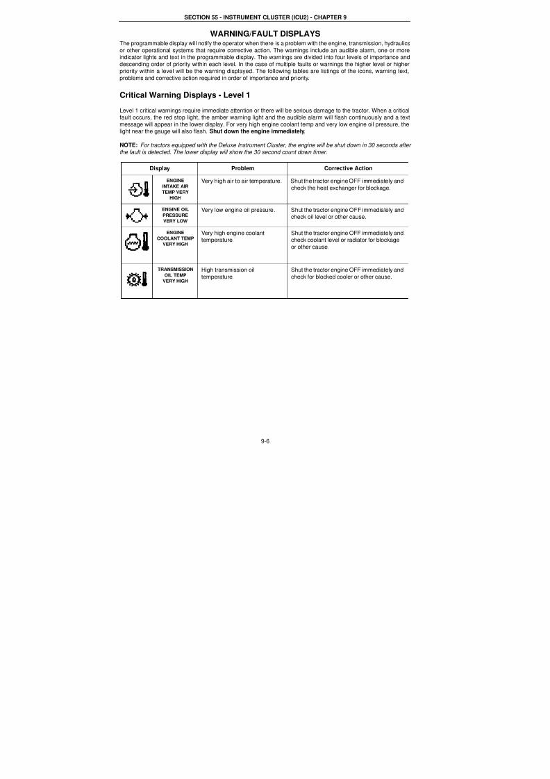
WARNING/FAULT DISPLAYSThe programmable display will notify the operator when there is a problem with the engine, transmission, hydraulics
or other operational systems that require corrective action. The warnings include an audible alarm, one or moreindicator lights and text in the programmable display. The warnings are divided into four levels of importance and
descending order of priority within each level. In the case of multiple faults or warnings the higher level or higherpriority within a level will be the warning displayed. The following tables are listings of the icons, warning text,
problems and corrective action required in order of importance and priority.
Critical Warning Displays - Level 1
Level 1 critical warnings require immediate attention or there will be serious damage to the tractor. When a criticalfault occurs, the red stop light, the amber warning light and the audible alarm will flash continuously and a text
message will appear in the lower display. For very high engine coolant temp and very low engine oil pressure, thelight near the gauge will also flash. Shut down the engine immediately.
NOTE: For tractors equipped with the Deluxe Instrument Cluster, the engine will be shut down in 30 seconds after
the fault is detected. The lower display will show the 30 second count down timer.
Display Problem Corrective Action
ENGINE
INTAKE AIR
TEMP VERY
HIGH
Very high air to air temperature. Shut the tractor engine OFF immediately and
check the heat exchanger for blockage.
ENGINE OIL
PRESSURE
VERY LOW
Very low engine oil pressure. Shut the tractor engine OFF immediately andcheck oil level or other cause.
ENGINE
COOLANT TEMP
VERY HIGH
Very high engine coolanttemperature.
Shut the tractor engine OFF immediately andcheck coolant level or radiator for blockage
or other cause.
TRANSMISSION
OIL TEMP
VERY HIGH
High transmission oil
temperature.
Shut the tractor engine OFF immediately and
check for blocked cooler or other cause.
7/23/2019 Case Error Codes
http://slidepdf.com/reader/full/case-error-codes 7/140
SECTION 55 - INSTRUMENT CLUSTER (ICU2) - CHAPTER 9
9-7
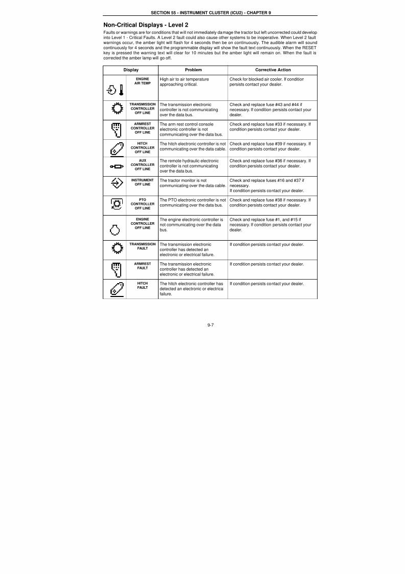
Non-Critical Displays - Level 2Faults or warnings are for conditions that will not immediately damage the tractor but left uncorrected could develop
into Level 1 - Critical Faults. A Level 2 fault could also cause other systems to be inoperative. When Level 2 faultwarnings occur, the amber light will flash for 4 seconds then be on continuously. The audible alarm will sound
continuously for 4 seconds and the programmable display will show the fault text continuously. When the RESETkey is pressed the warning text will clear for 10 minutes but the amber light will remain on. When the fault is
corrected the amber lamp will go off.
Display Problem Corrective Action
ENGINE
AIR TEMPHigh air to air temperature
approaching critical.
Check for blocked air cooler. If condition
persists contact your dealer.
TRANSMISSION
CONTROLLER
OFF LINE
The transmission electroniccontroller is not communicating
over the data bus.
Check and replace fuse #43 and #44 ifnecessary. If condition persists contact your
dealer.
ARMREST
CONTROLLEROFF LINE
The arm rest control console
electronic controller is notcommunicating over the data bus.
Check and replace fuse #33 if necessary. If
condition persists contact your dealer.
HITCH
CONTROLLER
OFF LINE
The hitch electronic controller is not
communicating over the data cable.
Check and replace fuse #39 if necessary. If
condition persists contact your dealer.
AUX
CONTROLLER
OFF LINE
The remote hydraulic electronic
controller is not communicatingover the data bus.
Check and replace fuse #36 if necessary. If
condition persists contact your dealer.
INSTRUMENT
OFF LINEThe tractor monitor is not
communicating over the data cable.
Check and replace fuses #16 and #37 if
necessary.If condition persists contact your dealer.
PTO
CONTROLLER
OFF LINE
The PTO electronic controller is not
communicating over the data bus.
Check and replace fuse #38 if necessary. If
condition persists contact your dealer.
ENGINE
CONTROLLER
OFF LINE
The engine electronic controller isnot communicating over the data
bus.
Check and replace fuse #1, and #15 ifnecessary. If condition persists contact your
dealer.
TRANSMISSION
FAULTThe transmission electronic
controller has detected anelectronic or electrical failure.
If condition persists contact your dealer.
ARMREST
FAULTThe transmission electronic
controller has detected anelectronic or electrical failure.
If condition persists contact your dealer.
HITCH
FAULTThe hitch electronic controller hasdetected an electronic or electrical
failure.
If condition persists contact your dealer.
7/23/2019 Case Error Codes
http://slidepdf.com/reader/full/case-error-codes 8/140
SECTION 55 - INSTRUMENT CLUSTER (ICU2) - CHAPTER 9
9-8
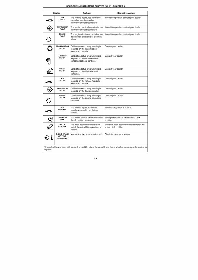
AUX
FAULTThe remote hydraulics electronic
controller has detected an
electronic or electrical failure.
If condition persists contact your dealer.
INSTRUMENT
FAULTThe tractor monitor has detected anelectronic or electrical failure.
If condition persists contact your dealer.
ENGINE
FAULTThe engine electronic controller has
detected an electronic or electrical
failure.
If condition persists contact your dealer.
*TRANSMISSION
SETUPCalibration setup programming isrequired on the transmission
electronic controller.
Contact your dealer.
*ARMREST
SETUPCalibration setup programming is
required on the arm rest controlconsole electronic controller
Contact your dealer.
*HITCH
SETUPCalibration setup programming isrequired on the hitch electronic
controller.
Contact your dealer.
*AUX
SETUPCalibration setup programming isrequired on the remote hydraulic
electronic controller.
Contact your dealer.
*INSTRUMENT
SETUPCalibration setup programming is
required on the tractor monitor.
Contact your dealer.
*ENGINESETUP
Calibration setup programming isrequired on the engine electronic
controller.
Contact your dealer.
*AUX
NEUTRALThe remote hydraulic control
lever(s) were not in neutral onstartup.
Move lever(s) back to neutral.
*TURN PTO
OFFThe power take off switch was not inthe off position on startup.
Move power take off switch to the OFFposition.
*HITCH
CAPTURE
The hitch position control did not
match the actual hitch position onstartup.
Move the hitch position control to match the
actual hitch position.
ENGINE INTAKE
AIR TEMP
SENSOR FAULT
Mechanical fuel pump models only. Check this sensor or wiring.
*These faults/warnings will cause the audible alarm to sound three times which means operator action isrequired.
Display Problem Corrective Action
7/23/2019 Case Error Codes
http://slidepdf.com/reader/full/case-error-codes 9/140
SECTION 55 - INSTRUMENT CLUSTER (ICU2) - CHAPTER 9
9-9
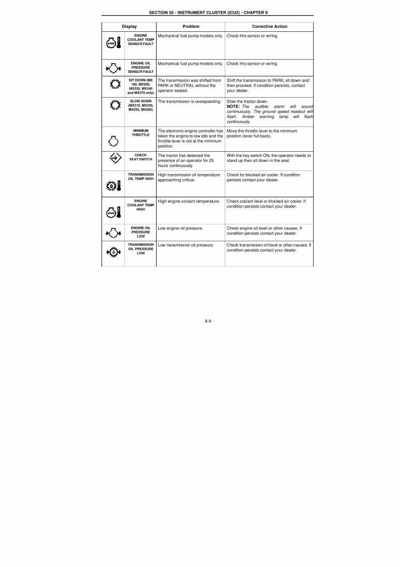
ENGINE
COOLANT TEMP
SENSOR FAULT
Mechanical fuel pump models only. Check this sensor or wiring.
ENGINE OILPRESSURE
SENSOR FAULT
Mechanical fuel pump models only. Check this sensor or wiring.
SIT DOWN (MX
180, MX200,
MX220, MX240
and MX270 only)
The transmission was shifted from
PARK or NEUTRAL without the
operator seated.
Shift the transmission to PARK, sit down and
then proceed. If condition persists, contact
your dealer.
SLOW DOWN
(MX210, MX230,
MX255, MX285)
The transmission is overspeeding. Slow the tractor down.NOTE: The audible alarm will sound continuously. The ground speed readout will
flash. Amber warning lamp will flash continuously.
MINIMUM
THROTTLEThe electronic engine controller has
taken the engine to low idle and thethrottle lever is not at the minimum
position.
Move the throttle lever to the minimum
position (lever full back).
CHECK
SEAT SWITCHThe tractor has detected thepresence of an operator for 25
hours continuously.
With the key switch ON, the operator needs tostand up then sit down in the seat.
TRANSMISSION
OIL TEMP HIGHHigh transmission oil temperature
approaching critical.
Check for blocked air cooler. If condition
persists contact your dealer.
ENGINE
COOLANT TEMP
HIGH
High engine coolant temperature. Check coolant level or blocked air cooler. If
condition persists contact your dealer.
ENGINE OIL
PRESSURE
LOW
Low engine oil pressure. Check engine oil level or other causes. If
condition persists contact your dealer.
TRANSMISSION
OIL PRESSURE
LOW
Low transmission oil pressure. Check transmission oil level or other causes. If
condition persists contact your dealer.
Display Problem Corrective Action
7/23/2019 Case Error Codes
http://slidepdf.com/reader/full/case-error-codes 10/140
SECTION 55 - INSTRUMENT CLUSTER (ICU2) - CHAPTER 9
9-10
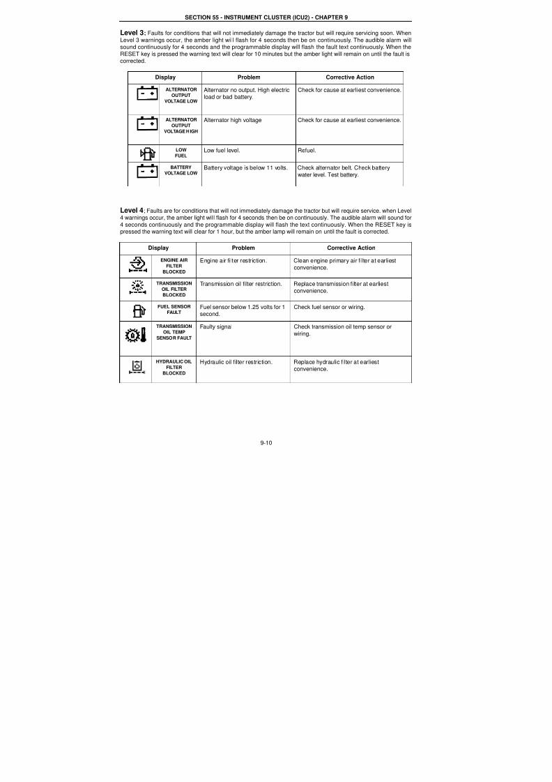
Level 3; Faults for conditions that will not immediately damage the tractor but will require servicing soon. When
Level 3 warnings occur, the amber light wil l flash for 4 seconds then be on continuously. The audible alarm willsound continuously for 4 seconds and the programmable display will flash the fault text continuously. When the
RESET key is pressed the warning text will clear for 10 minutes but the amber light will remain on until the fault iscorrected.
Level 4; Faults are for conditions that will not immediately damage the tractor but will require service. when Level4 warnings occur, the amber light will flash for 4 seconds then be on continuously. The audible alarm will sound for
4 seconds continuously and the programmable display will flash the text continuously. When the RESET key ispressed the warning text will clear for 1 hour, but the amber lamp will remain on until the fault is corrected.
Display Problem Corrective Action
ALTERNATOROUTPUT
VOLTAGE LOW
Alternator no output. High electricload or bad battery.
Check for cause at earliest convenience.
ALTERNATOR
OUTPUT
VOLTAGE HIGH
Alternator high voltage Check for cause at earliest convenience.
LOW
FUELLow fuel level. Refuel.
BATTERY
VOLTAGE LOWBattery voltage is below 11 volts. Check alternator belt. Check battery
water level. Test battery.
Display Problem Corrective Action
ENGINE AIR
FILTERBLOCKED
Engine air filter restriction. Clean engine primary air filter at earliest
convenience.
TRANSMISSION
OIL FILTER
BLOCKED
Transmission oil filter restriction. Replace transmission filter at earliestconvenience.
FUEL SENSOR
FAULTFuel sensor below 1.25 volts for 1second.
Check fuel sensor or wiring.
TRANSMISSION
OIL TEMP
SENSOR FAULT
Faulty signal Check transmission oil temp sensor or
wiring.
HYDRAULIC OIL
FILTER
BLOCKED
Hydraulic oil filter restriction. Replace hydraulic filter at earliestconvenience.
7/23/2019 Case Error Codes
http://slidepdf.com/reader/full/case-error-codes 11/140
SECTION 55 - INSTRUMENT CLUSTER (ICU2) - CHAPTER 9
9-11
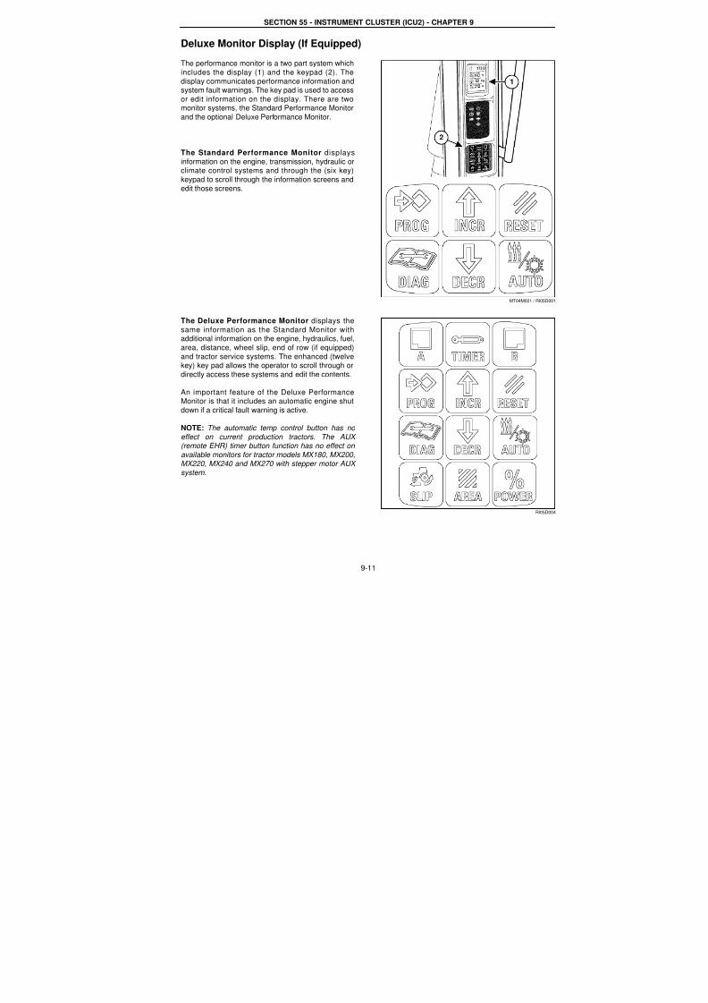
Deluxe Monitor Display (If Equipped)
The performance monitor is a two part system which
includes the display (1) and the keypad (2). The
display communicates performance information andsystem fault warnings. The key pad is used to access
or edit information on the display. There are twomonitor systems, the Standard Performance Monitor
and the optional Deluxe Performance Monitor.
The Standard Performance Monitor displays
information on the engine, transmission, hydraulic orclimate control systems and through the (six key)
keypad to scroll through the information screens and
edit those screens.
The Deluxe Performance Monitor displays the
same information as the Standard Monitor with
additional information on the engine, hydraulics, fuel,area, distance, wheel slip, end of row (if equipped)
and tractor service systems. The enhanced (twelvekey) key pad allows the operator to scroll through or
directly access these systems and edit the contents.
An important feature of the Deluxe PerformanceMonitor is that it includes an automatic engine shut
down if a critical fault warning is active.
NOTE: The automatic temp control button has no
effect on current production tractors. The AUX (remote EHR) timer button function has no effect on
available monitors for tractor models MX180, MX200,MX220, MX240 and MX270 with stepper motor AUX
system.
MT04M021 / RI05D00
1
2
RI05D00
7/23/2019 Case Error Codes
http://slidepdf.com/reader/full/case-error-codes 12/140
9-12
Template Name: OML_2_col Rac 0-00000Template Date: 2001_03_06
SECTION 55 - INSTRUMENT CLUSTER (ICU2) - CHAPTER 9
INSTRUMENTATION PROGRAMMING
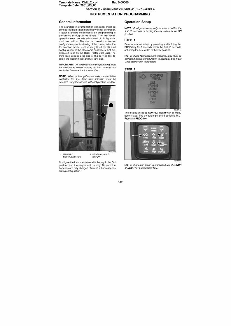
General Information
The standard instrumentation controller must beconfigured/calibrated before any other controller.
Tractor Standard instrumentation programming is
performed through three levels. The first level,operation setup permits adjustment of display units
and t ire radius. The second level, control lerconfiguration permits viewing of the current selection
for t ractor model (set dur ing third level) andconfiguration of the electronic controllers that are
expected to be on the TDB (Tractor Data Bus). The
third level requires the use of the service tool to
select the tractor model and fuel tank size.
IMPORTANT: All three levels of programming must
be performed when moving an instrumentation controller from one tractor to another.
NOTE: When replacing the standard instrumentation
controller the fuel tank size selection must be
selected using the service tool configuration window.
MD05F002
Configure the instrumentation with the key in the ONposition and the engine not running. Be sure the
batteries are fully charged. Turn off all accessoriesduring configuration.
Operation Setup
NOTE: Configuration can only be entered within the
first 10 seconds of turning the key switch to the ONposition.
STEP 1
Enter operation setup by pressing and holding the
PROG key for 3 seconds within the first 10 secondsof turning the key switch to the ON position.
NOTE: If any fault codes are recorded, they must be
corrected before configuration is possible. See Faul
Code Retrieval in this section.
STEP 2
RD05F10
The display will read CONFIG MENU with all menuitems listed. The default highlighted option is ICU
Press the PROG key.
MD05F00
NOTE: If another option is highlighed use the INCR
or DECR keys to highlight ICU .
1. STANDARD
INSTRUMENTATION
2. PROGRAMMABLE
DISPLAY
1
2
7/23/2019 Case Error Codes
http://slidepdf.com/reader/full/case-error-codes 13/140
SECTION 55 - INSTRUMENT CLUSTER (ICU2) - CHAPTER 9
9-13
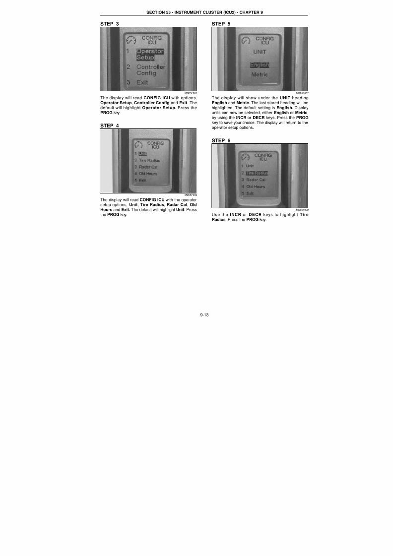
STEP 3
MD05F005
The display will read CONFIG ICU with options,Operator Setup, Controller Config and Exit. The
default will highlight Operator Setup. Press thePROG key.
STEP 4
MD05F006
The display will read CONFIG ICU with the operatorsetup options, Unit, Tire Radius, Radar Cal, Old
Hours and Exit. The default will highlight Unit. Pressthe PROG key.
STEP 5
MD05F00
The display will show under the UNIT headingEnglish and Metric. The last stored heading will be
highlighted. The default setting is English. Displayunits can now be selected, either English or Metric
by using the INCR or DECR keys. Press the PROG
key to save your choice. The display will return to theoperator setup options.
STEP 6
MD05F00
Use the INCR or DECR keys to highlight Tire
Radius. Press the PROG key.

7/23/2019 Case Error Codes
http://slidepdf.com/reader/full/case-error-codes 14/140
SECTION 55 - INSTRUMENT CLUSTER (ICU2) - CHAPTER 9
9-14
STEP 7
MD05F010
The display will read TIRE RADIUS with the radiusicon above the MANUAL or AUTO options. Use the
INCR and DECR keys to select either MANUAL orAUTO format. Press the PROG key to enter the
selected format.
If MANUAL is selected, proceed to Step 8. If AUTO(automatic) is selected, proceed to Step 9.
STEP 8
MD05F011
When the MANUAL format is selected the display
will read TIRE RADIUS with the radius icon above
the previously saved radius.
1. Use the INCR or DECR keys to change the
radius number by 1 mm (0.1 inch). Pressing and
holding the INCR or DECR keys will rapidlychange the radius number.
2. When the correct radius number is reached,
press the PROG key to save that number.
STEP 9
MD0F012
To use the AUTO format for determining tire radiusthe following preparations must be made:
1. Mark a straight-line course of 60 meters (196.86
feet) with a start line and finish line that can beclearly seen from the cab.
2. Position the tractor at an adequate distance fromthe start line to allow the tractor to achieve andmaintain a steady speed faster than 2 MPH (3.22
KPH).
3. Turn the key switch OFF. Press and hold thePROG key for 3 seconds within the first 10
seconds of starting the engine.
4. The display will read CONFIG MENU and a list ofoptions. With the ICU highlighted press the
PROG key.
5. The display will read CONFIG MENU followed by
Operator Setup, Controller Config and Exit.With Operator Setup highlighted press thePROG key.
6. The display will show the CONFIG ICU options.
Use the INCR or DECR keys to select TireRadius and press the PROG key.
7. The display will read TIRE RADIUS with the
radius icon above the MANUAL or AUTOoptions. Use the INCR or DECR keys to select
AUTO and press the PROG key.
7/23/2019 Case Error Codes
http://slidepdf.com/reader/full/case-error-codes 15/140
SECTION 55 - INSTRUMENT CLUSTER (ICU2) - CHAPTER 9
9-15
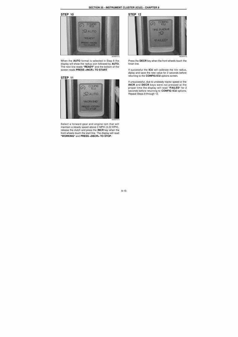
STEP 10
MD05F013
When the AUTO format is selected in Step 9 the
display will show the radius icon followed by AUTO.The next line reads *READY* and the bottom of the
screen reads PRESS <INCR> TO START.
STEP 11
MD05F014
Select a forward gear and engine rpm that will
maintain a steady speed above 2 MPH (3.22 KPH),release the clutch and press the INCR key when the
front wheels touch the start line. The display will read*WORKING* and PRESS <DECR> TO STOP.
STEP 12
MD05F01
Press the DECR key when the front wheels touch the
finish line.
If successful the ICU will calibrate the tire radiusdiplay and save the new value for 2 seconds before
returning to the CONFIG ICU options screen.
If unsuccessful, due to unsteady tractor speed or the
INCR and DECR keys were not pressed at theproper time the display will read *FAILED* for 2
seconds before returning to CONFIG ICU optionsRepeat Steps 9 through 12.
7/23/2019 Case Error Codes
http://slidepdf.com/reader/full/case-error-codes 16/140
SECTION 55 - INSTRUMENT CLUSTER (ICU2) - CHAPTER 9
9-16
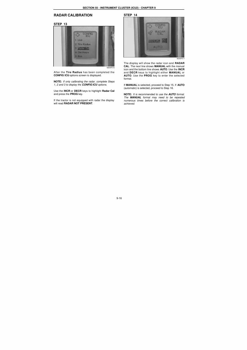
RADAR CALIBRATION
STEP 13
MD05F016
After the Tire Radius has been completed theCONFIG ICU options screen is displayed.
NOTE: If only calibrating the radar, complete Steps
1, 2 and 3 to display the CONFIG ICU options.
Use the INCR or DECR keys to highlight Radar Cal
and press the PROG key.
If the tractor is not equipped with radar the display
will read RADAR NOT PRESENT.
STEP 14
MD05F017
The display will show the radar icon and RADAR
CAL. The next line shows MANUAL with the manualicon and the bottom line shows AUTO. Use the INCR
and DECR keys to highlight either MANUAL orAUTO. Use the PROG key to enter the selected
format.
If MANUAL is selected, proceed to Step 15. If AUTO
(automatic) is selected, proceed to Step 16.
NOTE: It is recommended to use the AUTO format.The MANUAL format may need to be repeated
numerous times before the correct calibration is achieved.
7/23/2019 Case Error Codes
http://slidepdf.com/reader/full/case-error-codes 17/140
SECTION 55 - INSTRUMENT CLUSTER (ICU2) - CHAPTER 9
9-17
STEP 15
MD05F018
When the MANUAL format is sected the display will
show the radar icon followed by RADAR CAL. Thebottom of the display will show the previously saved
or default (27.47) calibration number.
1. Use the INCR or DECR keys to change thenumber. Decrease the number to increase radar
read out speed and reduce the percentage of slipdisplayed during operation. Increase the number
to decrease the read out speed and increase thepercentage of slip display.
2. When the corrected calibration number is
reached, press the PROG key to save thatnumber.
STEP 16
MD05F019
To use the AUTO format for determining the radarcalibration the following preparations must be made:
1. Mark a straight-line course of 60 meters (196.86
feet) with a start line and finish line that can beclearly seen from the cab.
2. Position the tractor at an adequate distance from
the start line to allow the tractor to achieve andmaintain a steady speed faster than 2 MPH (3.22
KPH).
3. Turn the key switch OFF. Press and hold the
PROG key for 3 seconds within the first 10seconds of starting the engine.
4. The display will read CONFIG MENU. With ICU
highlighted press the PROG key.
5. The display will show the CONFIG ICU optionsUse the INCR or DECR keys to select Radar Ca
and press the PROG key.
6. The display will show the radar icon followed byRADAR CAL. The next line reads MANUAL
followed by the manual icon and the bottom linereads AUTO. Use the INCR o r DECR key to
select AUTO and press the PROG key.
STEP 17
MD05F02
When the AUTO format is selected in Step 16 the
display will show the radar icon and RADAR CAL
The next line reads AUTO and below that *READY*The bottom of the screen reads PRESS <INCR> TOSTART.
STEP 18
MD05F02
Select a forward gear and engine rpm that wil
maintain a steady speed above 2 MPH (3.22 KPA)
release the clutch and press the INCR key when thefront wheels touch the start line. the display will read
*WORKING* and PRESS <DECR> TO STOP,
7/23/2019 Case Error Codes
http://slidepdf.com/reader/full/case-error-codes 18/140
SECTION 55 - INSTRUMENT CLUSTER (ICU2) - CHAPTER 9
9-18
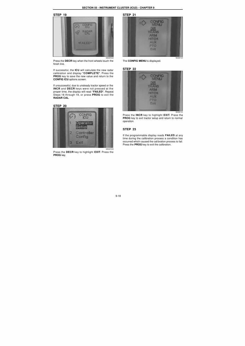
STEP 19
MD05F022
Press the DECR key when the front wheels touch thefinish line.
If successful, the ICU will calculate the new radar
calibration and display *COMPLETE*. Press the
PROG key to save the new value and return to theCONFIG ICU options screen.
If unsuccessful, due to unsteady tractor speed or the
INCR and DECR keys were not pressed at theproper time, the display will read *FAILED*, Repeat
Steps 16 through 19, or press PROG to exit the
RADAR CAL.
STEP 20
MD05F005
Press the DECR key to highlight EXIT. Press thePROG key.
STEP 21
RD05F101
The CONFIG MENU is displayed.
STEP 22
RD05F101
Press the INCR key to highlight EXIT. Press the
PROG key to exit tractor setup and return to normaloperation.
STEP 23
If the programmable display reads FAILED at anytime during the calibration process a condition has
occurred which caused the calibration process to fail.Press the PROG key to exit the calibration.
7/23/2019 Case Error Codes
http://slidepdf.com/reader/full/case-error-codes 19/140
SECTION 55 - INSTRUMENT CLUSTER (ICU2) - CHAPTER 9
9-19
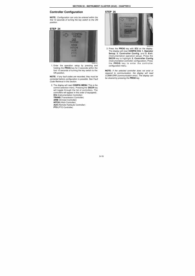
Controller Configuration
NOTE: Configuration can only be entered within the
first 10 seconds of turning the key switch to the ON
position.
STEP 24
RD05F101
1. Enter the operation setup by pressing andholding the PROG key for 3 seconds within the
first 10 seconds of turning the key switch to theON position.
NOTE: If any fault codes are recorded, they must be
corrected before configuration is possible. See Fault
Code Retrieval in this section.
2. The display will read CONFIG MENU. This is the
control selection menu. Pressing the DECR key
will toggle through the list of controllers. The
controllers will appear in this order (if equipped):ICU (Instrumentation Controller)TRANS (Transmission Controller)
ARM (Armrest Controller)HITCH (Hitch Controller)
AUX (Remote Hydraulic Controller)PTO (PTO Controller)
STEP 25
MD05F02
3. Press the PROG key with ICU on the displayThe display will read CONFIG ICU, 1. Operator
Setup, 2. Controller Config, and 3. Exit(Instrumentation operation setup). Press the
DECR key to highlight 2. Controller Config
(Instrumentation controller configuration). Pressthe PROG key to en te r the con t ro l le
configuration menu.
NOTE: If the selected controller does not exist orespond to communication, the display will read
COMM ERR (communication error). The display can
be cleared by pressing the PROG key.
7/23/2019 Case Error Codes
http://slidepdf.com/reader/full/case-error-codes 20/140
SECTION 55 - INSTRUMENT CLUSTER (ICU2) - CHAPTER 9
9-20
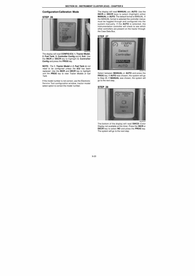
Configuration/Calibration Mode
STEP 26
MD05F026
The display will read CONFIG ICU, 1. Tractor Model,
2. Fuel Tank, 3. Controller Config and 4. Exit. Usethe INCR or DECR key to highlight 3. Controller
Config and press the PROG key.
NOTE: The 1. Tractor Model or 2. Fuel Tank do not need to be configured unless the ICU has been
replaced. Use the INCR and DECR key to highlight
and the PROG key to view Tractor Models or fuel Tank.
If the model number is not correct, use the Electronic
Service Tool configuration w indow, tractor model
select option to correct the model number.
The display will read MANUAL and AUTO. Use the
INCR o r DECR keys to select (highlight) eitherMANUAL or AUTO. The default format is MANUAL. If
the MANUAL format is selected the controller menusmust be toggled through and configured into the
system manually. If the AUTO is selected, the
instrumentation controller will check to see whichother controllers are present on the tractor through
the Case Data Bus.
STEP 27
MD05F174
Select between MANUAL or AUTO and press the
PROG key. If AUTO was chosen, the system will go
to Step 35. If MANUAL was chosen, the system willgo to the next step.
STEP 28
MD05F027
The bottom of the display will read SWCD (Color
Display not available at this time). Press the INCR orDECR key to select NO and press the PROG key.The system will go to the next step.
7/23/2019 Case Error Codes
http://slidepdf.com/reader/full/case-error-codes 21/140
SECTION 55 - INSTRUMENT CLUSTER (ICU2) - CHAPTER 9
9-21
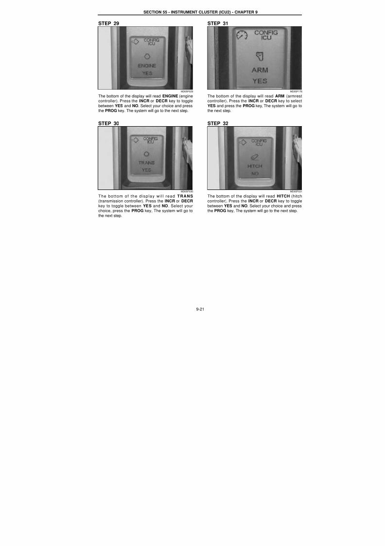
STEP 29
MD05F029
The bottom of the display will read ENGINE (enginecontroller). Press the INCR or DECR key to toggle
between YES and NO. Select your choice and pressthe PROG key. The system will go to the next step.
STEP 30
MD05F030
The bot tom of the d isp lay wi l l read TRANS(transmission controller). Press the INCR or DECR
key to toggle between YES and NO. Select yourchoice, press the PROG key, The system will go to
the next step.
STEP 31
MD05F17
The bottom of the display will read ARM (armrescontroller). Press the INCR or DECR key to selec
YES and press the PROG key, The system will go tothe next step.
STEP 32
MD05F03
The bottom of the display will read HITCH (hitchcontroller). Press the INCR or DECR key to toggle
between YES and NO. Select your choice and pressthe PROG key, The system will go to the next step.
7/23/2019 Case Error Codes
http://slidepdf.com/reader/full/case-error-codes 22/140
SECTION 55 - INSTRUMENT CLUSTER (ICU2) - CHAPTER 9
9-22
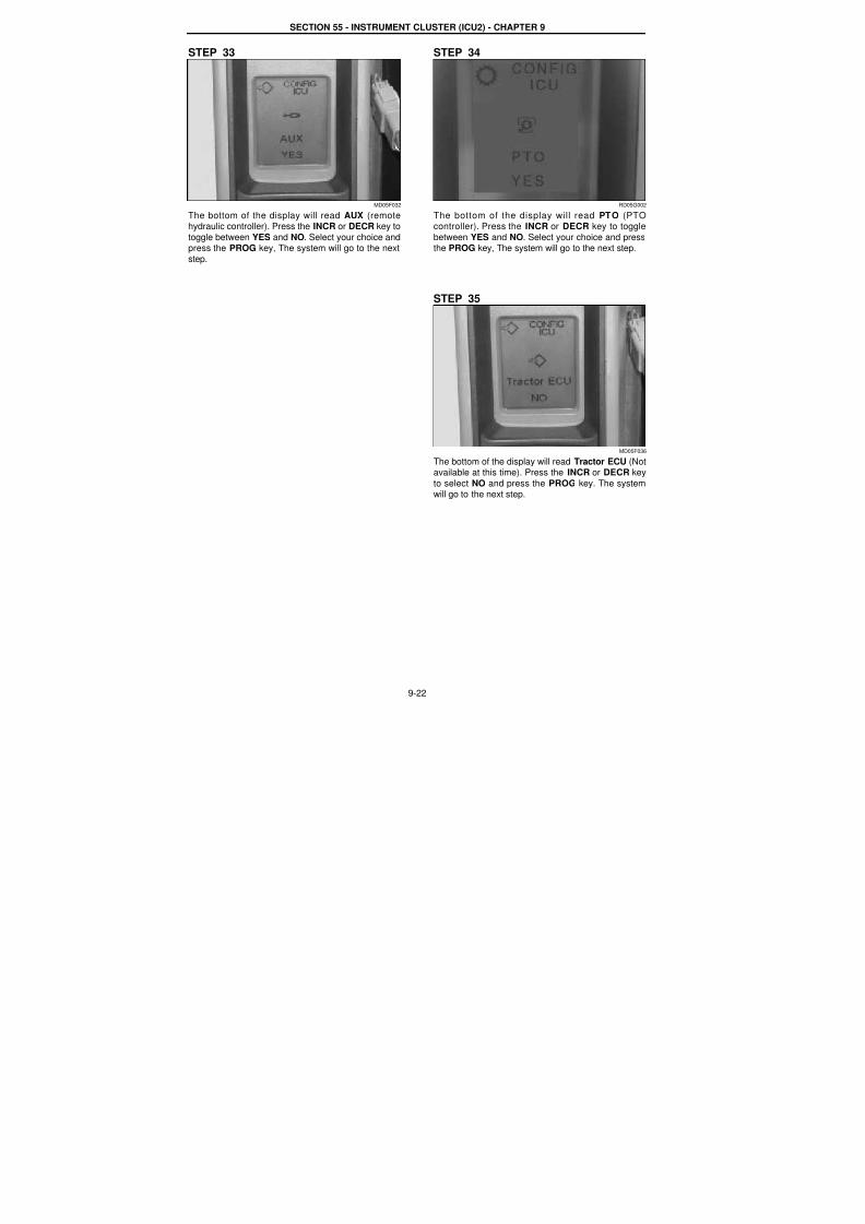
STEP 33
MD05F032
The bottom of the display will read AUX (remotehydraulic controller). Press the INCR or DECR key to
toggle between YES and NO. Select your choice andpress the PROG key, The system will go to the next
step.
STEP 34
RD05G002
The bottom of the display will read PTO (PTOcontroller). Press the INCR or DECR key to toggle
between YES and NO. Select your choice and pressthe PROG key, The system will go to the next step.
STEP 35
MD05F036
The bottom of the display will read Tractor ECU (Notavailable at this time). Press the INCR or DECR key
to select NO and press the PROG key. The systemwill go to the next step.
7/23/2019 Case Error Codes
http://slidepdf.com/reader/full/case-error-codes 23/140
SECTION 55 - INSTRUMENT CLUSTER (ICU2) - CHAPTER 9
9-23
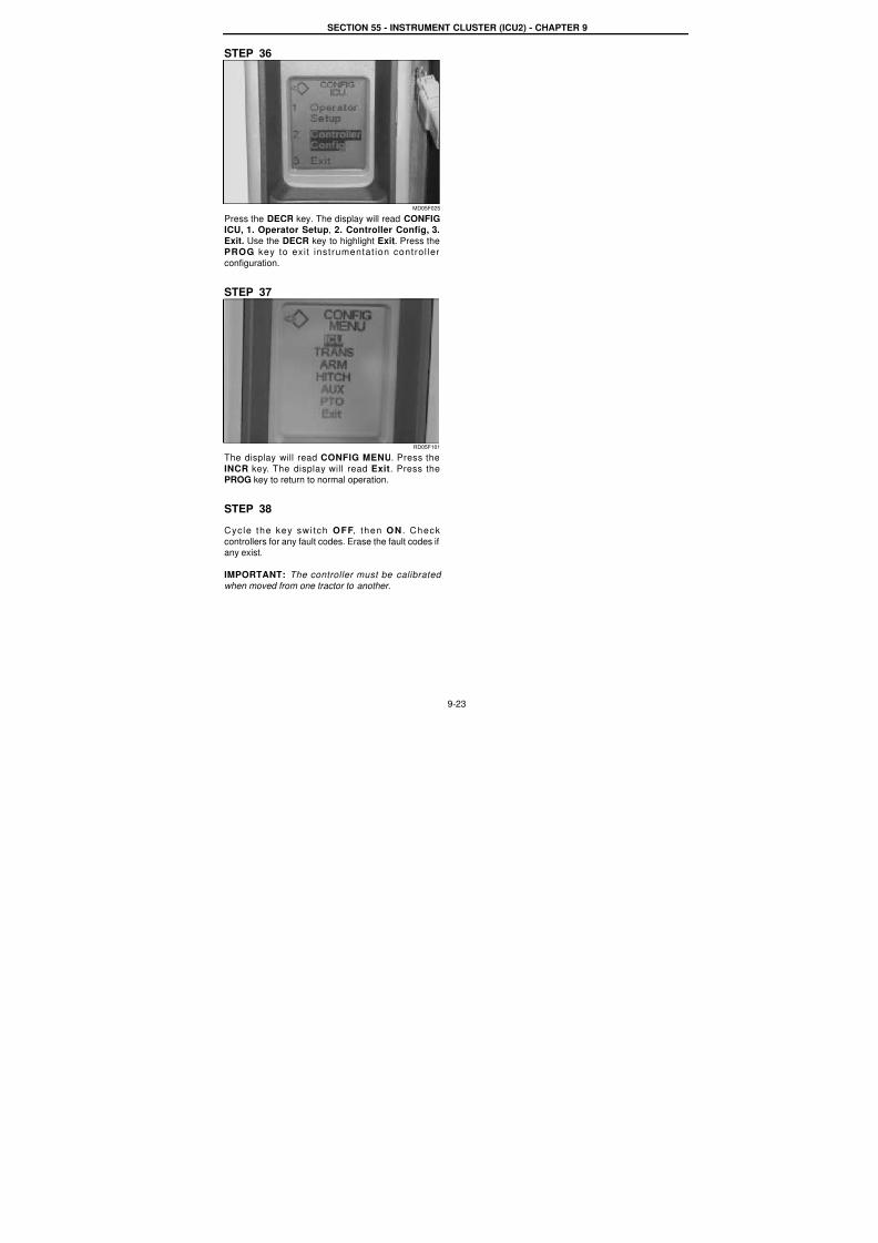
STEP 36
MD05F025
Press the DECR key. The display will read CONFIGICU, 1. Operator Setup, 2. Controller Config, 3.
Exit. Use the DECR key to highlight Exit. Press thePROG key to exit instrumentat ion control ler
configuration.
STEP 37
RD05F101
The display will read CONFIG MENU. Press the
INCR key. The display will read Exit. Press thePROG key to return to normal operation.
STEP 38
Cycle the key swi tch OFF, then ON . Check
controllers for any fault codes. Erase the fault codes ifany exist.
IMPORTANT: The controller must be calibrated
when moved from one tractor to another.
7/23/2019 Case Error Codes
http://slidepdf.com/reader/full/case-error-codes 24/140
9-24
Template Name: OML_2_col Rac 0-00000Template Date: 2001_03_06
SECTION 55 - INSTRUMENT CLUSTER (ICU2) - CHAPTER 9
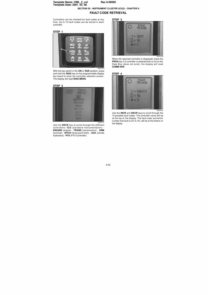
FAULT CODE RETRIEVAL
Controllers can be checked for fault codes at anytime. Up to 10 fault codes can be stored in each
controller.
STEP 1
MD05F003
With the key switch in the ON or RUN position, pressand hold the DIAG key on the programmable display
key board to enter the controller selection screen.
The display will read DIAG MENU.
STEP 2
RD05F161
Use the DECR key to scroll through the d ifferentcontrollers: ICU (standard instrumentation) -
ENGINE (engine) - TRANS (transmission) - ARM
(armrest) - HITCH (three point hitch) - AUX (remotehydraulics) - PTO (PTO Controller).
STEP 3
MD05F04
When the required controller is displayed, press the
PROG key. If a controller is selected that is not on theData Bus (does not exist), the display will read
COMM ERR.
STEP 4
MD05F04
Use the INCR and DECR keys to scroll through the
10 possible fault codes. The controller name will beat the top of the display. The fault code and which
number that fault is (01 to 10), will be at the bottom othe display.
7/23/2019 Case Error Codes
http://slidepdf.com/reader/full/case-error-codes 25/140
SECTION 55 - INSTRUMENT CLUSTER (ICU2) - CHAPTER 9
9-25
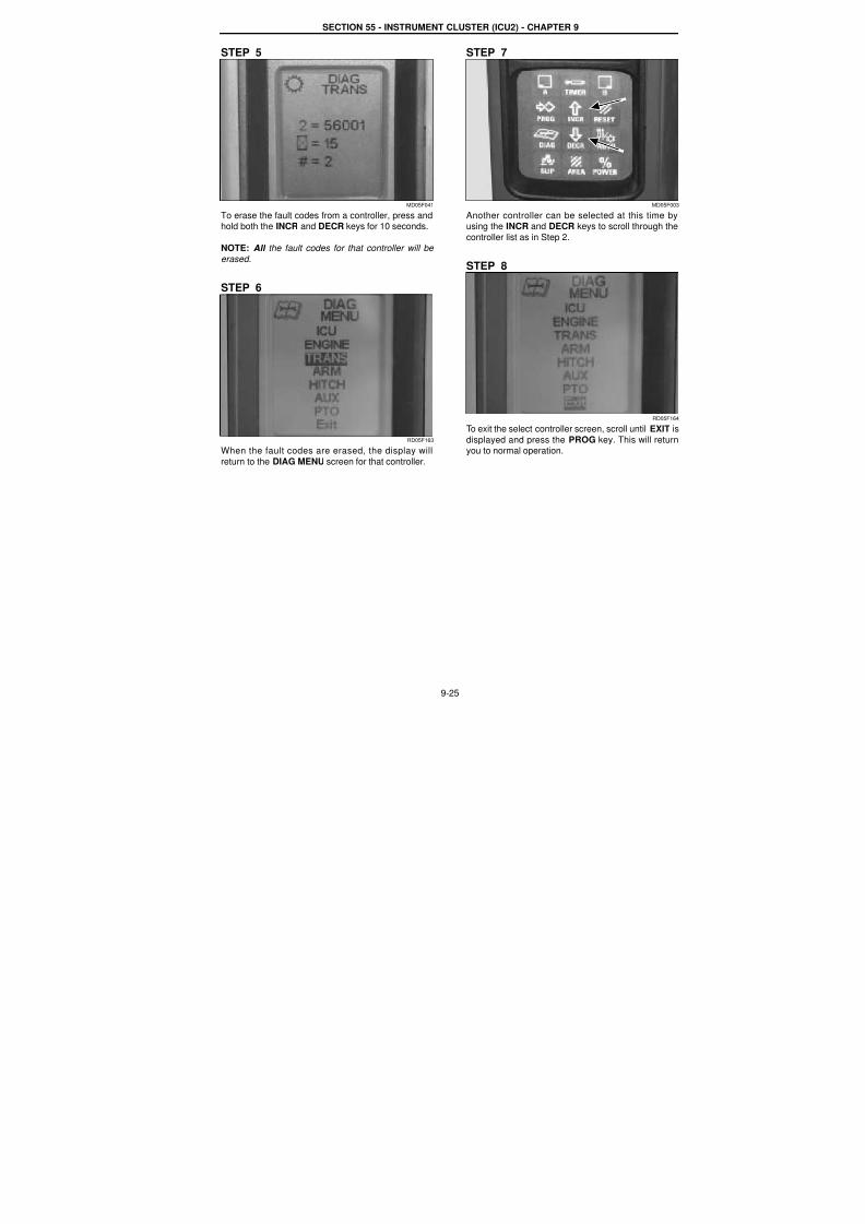
STEP 5
MD05F041
To erase the fault codes from a controller, press andhold both the INCR and DECR keys for 10 seconds.
NOTE: All the fault codes for that controller will be
erased.
STEP 6
RD05F163
When the fault codes are erased, the display will
return to the DIAG MENU screen for that controller.
STEP 7
MD05F00
Another controller can be selected at this time byusing the INCR and DECR keys to scroll through the
controller list as in Step 2.
STEP 8
RD05F16
To exit the select controller screen, scroll until EXIT is
displayed and press the PROG key. This will returnyou to normal operation.
7/23/2019 Case Error Codes
http://slidepdf.com/reader/full/case-error-codes 26/140
SECTION 55 - INSTRUMENT CLUSTER (ICU2) - CHAPTER 9
9-26
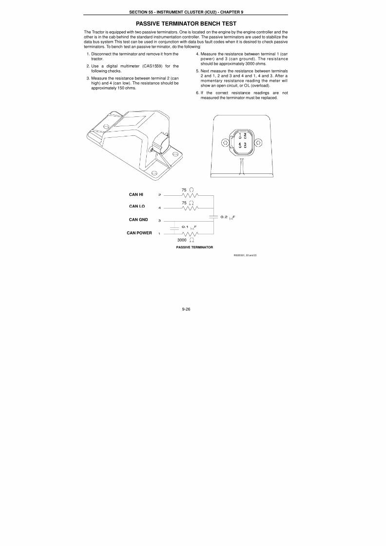
PASSIVE TERMINATOR BENCH TEST
The Tractor is equipped with two passive terminators. One is located on the engine by the engine controller and the
other is in the cab behind the standard instrumentation controller. The passive terminators are used to stabilize thedata bus system This test can be used in conjunction with data bus fault codes when it is desired to check passive
terminators. To bench test an passive terminator, do the following:
1. Disconnect the terminator and remove it from thetractor.
2. Use a digital multimeter (CAS1559) for the
following checks.
3. Measure the resistance between terminal 2 (canhigh) and 4 (can low). The resistance should be
approximately 150 ohms.
4. Measure the resistance between terminal 1 (canpower) and 3 (can ground). The resistance
should be approximately 3000 ohms.
5. Next measure the resistance between terminals2 and 1, 2 and 3 and 4 and 1, 4 and 3. After a
momentary resistance reading the meter willshow an open circuit, or OL (overload).
6. If the correct resistance readings are not
measured the terminator must be replaced.
RI02E021, 22 and 23
PASSIVE TERMINATOR
CAN HI
CAN LO
CAN GND
CAN POWER
75
75
3000
7/23/2019 Case Error Codes
http://slidepdf.com/reader/full/case-error-codes 27/140
9-27
Template Name: OML_2_col Rac 0-00000Template Date: 2001_03_06
SECTION 55 - INSTRUMENT CLUSTER (ICU2) - CHAPTER 9
SYMPTOM BASED FAULTS - NO FAULT CODESInstrumentation Display Will Not Illuminate When Key Is Turned On
No Fault Code
Meaning:The INST controller (display) is not to be powered or
has failed.
Possible failure mode:1. Failed cab power relay - engine will run after
starting.
2. Failed controller power relay - engine will stopafter starting.
3. Failed key switch - engine will stop after starting.4. Fuse #37 failed or circuit from fuse to controller
pin 2 of connector CN2 failed open.
5. Poor ground supply to Display pin 4 of connector
CN2.
Background:The key switch activates the cab power relay and the
controller relay when the key is placed in the startand run position. The cab power relay supplies
battery power (switched power) to the controller relay.
Both relays must be powered for the controllers to bepowered.
NOTE: Both the cab power relay and the controller
relay must make a clicking sound when the key is turned on.
Wiring information:
Instrumentation controller connector CN2-2<--->Fuse 37<--->241 (Controller relay) 241<--->138
(cab power relay)
240<--->unswitched power
Corrective action:
STEP 1 - Cycle key switch - (20 times)Turn the front wiper on.Turn the key switch on and off while monitoring the
display and the front wiper, the display and frontwiper must turn on and off everytime when the key is
cycled.
-- OK - The display and front wiper turned on everytime when key switch was turned on.
-- NOT OK - The wiper turned on but the display didnot turn on when the key was turned on. Go to Step
4.-- NOT OK - The display and the wiper did not turn
on, go to Step 2.
STEP 2 - Check power to cab powerrelayThe cab power re lay is located in the fuse
compartment behind the operator seat.Turn the key on, the relay should make a clicking
sound.
-- OK - Relay clicks, but wiper did not turn on -Replace relay (failed contacts).
-- NOT OK - Relay did not click - Check power supply
to relay. Go to Step 3.STEP 3 - Check power and ground to thecab power relayCheck relay ground - correct if needed.Turn key on.
Check for relay coil power at ring terminal 138 forswitched power from the key switch.
-- OK - Replace relay
-- NOT OK - Failed key switch
No power to key switchFailed wire from the key switch to relay
STEP 4 - Check fuse 37
With the key switch on the display will not illuminate.Check fuse 37.
-- OK - Go to Step 5.
-- NOT OK - Replace fuse, If fuse fails when key isturned on, go to Step 9.
7/23/2019 Case Error Codes
http://slidepdf.com/reader/full/case-error-codes 28/140
SECTION 55 - INSTRUMENT CLUSTER (ICU2) - CHAPTER 9
9-28
STEP 5 - Check power at fuse 37With the key switch on and the display not illuminate.Remove fuse 37 and check for 12 volts.
-- OK - Go to Step 7.-- NOT OK - Go to Step 6.
STEP 6 - Check controller relayThe controller relay is located in the fuse compartment behind the operator seat.
Check relay ground supply wire.Turn key on.
Check for relay coil power at ring terminal 241 at the Cab power relay.-- OK - Replace relay.
-- NOT OK - Failed wire from the controller relay to fuse 37.
STEP 7 - Check power and ground supply to the instrumentation controllerInstall fuse 37.
Remove the instrumentation controller.
Turn the key on.
Check connector CN2, pin 2 for 12 volts.-- NOT OK - Replace the wire between fuse 37 and the instrumentation controller connector CN2, pin 2.
-- OK - Go to Step 8.
STEP 8 - Check the ground supply at connector CN2, pin 4Check the ground supply at connector CN2, pin 4.
-- OK - Replace the instrumentation controller.
-- NOT OK - Correct grounding problem.
STEP 9 - Check the power supply to the instrumentation controllerInstall fuse 37.
Remove the instrumentation controller.Turn the key on.
Check connector CN2, pin 2 for 12 volts.-- NOT OK - fuse fails, Replace the wire between fuse 37 and the instrumentation controller connector CN2, pin 2.
-- OK - Plug the instrumentation controller in, If fuse 37 fails replace the instrumentation controller.
NOTE: If the problem is intermittent, one of the relays is starting to fail or has dirty contacts.
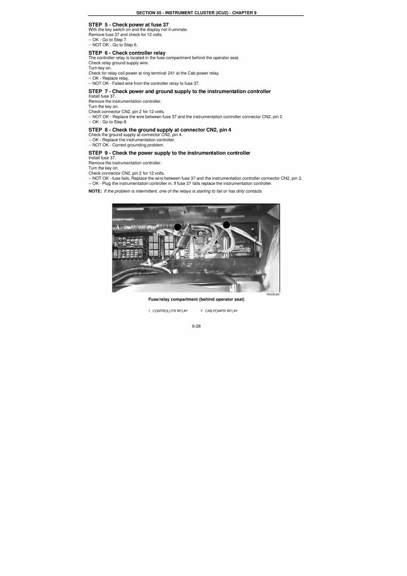
RD02E266
Fuse/relay compartment (behind operator seat)
1. CONTROLLER RELAY 2. CAB POWER RELAY
1 2
7/23/2019 Case Error Codes
http://slidepdf.com/reader/full/case-error-codes 29/140
SECTION 55 - INSTRUMENT CLUSTER (ICU2) - CHAPTER 9
9-29
The Tractor Will Start But The Display Does Not IlluminateNo Fault Code
Meaning:
The instrumentation controller (display) is not powered or has failed.
Possible failure mode:
1. Failed controller power relay - Engine will stop after starting.
2. Fuse #37 failed or circuit from fuse to controller pin 2 of connector CN2 failed open.3. Poor ground supply to Display pin 4 of connector CN2.
Background:
The key switch activates the cab power relay and the controller relay when the key is placed in the start and runposition. The cab power relay supplies battery power (switched power) to the controller relay. Both relays must be
powered for the controllers to be powered.
NOTE: Both the cab power relay and the controller relay must make a clicking sound when the key is turned on.
Wiring information:
Instrumentation controller connector CN2, pin 2<-->fuse 37<--> 241 (Controller relay) 241 <--> 138 (cab powe
relay) 240 <--> unswitched power
Corrective action:
STEP 1 - Check fuse 37With the key switch on and the display not illuminated.Check fuse 37.
-- OK - Go to Step 4.
- -NOT OK - Replace fuse, If fuse fails when replaced go to Step 6.
STEP 2 - Check power at fuse 37With the key switch on and the display not lit.
Check fuse 37.-- OK - Go to Step 4.
-- NOT OK - Go to Step 3.
STEP 3 - Check controller relay
The controller relay is located in the fuse compartment behind the operator seat.Check relay ground supply wire.Turn key on.
Check for relay coil power at pin 85 at the controller relay.
-- OK - Replace relay.-- NOT OK - Failed wire from the controller relay to fuse 30.
STEP 4 - Check the power supply to the instrumentation controllerInstall fuse 37.Remove the instrumentation controller.
Turn the key on.Check connector CN2, pin 2 for 12 volts.
-- NOT OK - Replace the wire between fuse 37 and the instrumentation controller connector CN2, pin 2.
-- OK - Go to Step 5.STEP 5 - Check the ground supply at connector CN2, pin 4Check the ground supply at connector CN2, pin 4.-- OK - Replace the instrumentation controller.
-- NOT OK - Correct grounding problem.

7/23/2019 Case Error Codes
http://slidepdf.com/reader/full/case-error-codes 30/140
SECTION 55 - INSTRUMENT CLUSTER (ICU2) - CHAPTER 9
9-30
STEP 6 - Check the power supply to the instrumentation controllerInstall fuse 37.Remove the instrumentation controller.
Turn the key on.Check connector CN2, pin 2 for 12 volts.
-- NOT OK - fuse fails, replace the wire between fuse 37 and the instrumentation controller connector CN2, pin 2.
-- OK - Plug the instrumentation controller in, If fuse 37 fails replace the instrumentation controller.
NOTE: If the problem is intermittent, the controller power relay is starting to fail or has dirty contacts.

7/23/2019 Case Error Codes
http://slidepdf.com/reader/full/case-error-codes 31/140
SECTION 55 - INSTRUMENT CLUSTER (ICU2) - CHAPTER 9
9-31
STANDARD INSTRUMENTATION CONTROLLER FAULT CODES
NOTE: Inputs that go out of range are considered in fault, and will be reported on the instrumentation display as
INST with the fault code number. Faults occurring on inputs that the instrumentation is not configured for will not be
reported as a fault
FAULT CODE INST 1015
Seat Switch Stuck ClosedCause:The switch is located in the seat cushion. The seat switch closes when the seat is sat in and opens when the
operator gets up. If the switch is closed for over 24 engine hours, this fault code will be recorded.
Possible failure mode:1. Seat switch stuck closed.
2. Seat switch wiring circuit problems.
Solution:Check the seat switch function.
Check the wiring from the instrumentation controller to the seat switch.
1. Check the seat switch function with the service tool. The seat switch status can be monitored through themonitor screen of the service tool.
Click the button ‘CHANGE PARAMETER SELECTIONS.’
When the ‘PARAMETER LIST’ screen shows up, select ‘SEAT OPERATOR PRESENT SW’ and add it to the‘VIEW LIST.’
Now you can monitor the function of the seat switch.Sit down and then stand up a few times.
The seat switch should close when the seat is sat in and open when the operator gets up.If the status on the screen changes with the operator’s position, the seat switch is functioning OK. The faul
code might be recorded for intermittent seat problems.
If the status on the screen does not change with the operator’s position, there is a problem with the seat switchor their wiring.
Go to the next Step.
2. Check the seat switch functionA. Disconnect the seat switch at the connector C133 (located behind seat).
B. Probe between pin 5 and pin 6 of connector C133. Seat switch must close when seat is sat in and openedwhen operator gets off the seat.
If the seat switch does not function correctly, check for the following:
A. Seat switch not located correctly in seat.B. Failed seat switch.
C. If the seat switch does function correctly, go to the next Step.
3. Check the wiring from the instrumentation controller to the seat switch connector C133There should be continuity from cavity 2 of connector CN1 to cavity 6 of connector C133.
There should be 12 VDC power supply at the cavity 5 of connector C133.
NOTE: Always inspect connector ends for damaged, bent or dislocated pins when troubleshooting.
NOTE: See schematic section 68 at the rear of this section.
7/23/2019 Case Error Codes
http://slidepdf.com/reader/full/case-error-codes 32/140
SECTION 55 - INSTRUMENT CLUSTER (ICU2) - CHAPTER 9
9-32
FAULT CODE INST 5011Engine Oil Pressure Sensor Signal Too Low
Cause:
The engine oil pressure sensor signal voltage is out of range low (the signal was below 0.25 volts for 1 second).
Possible failure modes:
1. Engine oil pressure sensor failed.
2. Engine oil pressure sensor wiring harness problems (open circuit, short to ground).
3. Instrument controller failure.
Solution
Check the engine oil pressure sensor resistance and the wiring from the instrumentation controller to the engine oil
pressure sensor.
1. Validate the pressure sensor power supply.Open up the tractor hood and locate the engine oil pressure sensor.
Disconnect connector C216 from the engine oil pressure sensor.Clean the connection. Clean the mating pin and connector. Inspect pin A, B, and C in the connector.
Measure the voltage at the supply input, pin B. It must be 5 volts.If it is as specified, go to the next Step.
If not, then check for 5 volts out of the instrument controller pin 8 at connector CN2.If there is not 5 volts at the controller, then pull pin 8 terminal out to determine if 5 volts is present on thecontroller pin when pin 8 wire is not connected.
NOTE: Use the correct tool to remove pins from connectors.
2. Check the sensor ground.Measure the continuity between pin A of connector C216 to the chassis ground.
If there is good continuity (less than 1 ohm), go to the next step.
If there is not good continuity, go to step 4.
3. Check the function of the engine oil pressure sensor.
Validate that the sensor output voltage is greater than 0.25 volts at pin C of connector C216.
If not, then replace the engine oil pressure sensor.
If yes, then validate that output voltage is present at the instrument controller input pin 23 at connector CN1. Ifthere is no voltage at the controller, then locate and repair an open circuit in the wire harness signal line.
4. Check the wiring from the engine oil pressure sensor connector C216 to connectors CN1 and CN2 at theinstrument controller.
There should be good continuity between pin A of C216 and the clean ground.There should be good continuity between pin B of C216 and pin 8 of connector CN2.
There should be good continuity between pin C of C216 and pin 23 of connector CN1.
If there is any open circuit, check the continuity from C216 to connectors CN1 and CN2 to locate the problem.
NOTE: Always inspect connector ends for damaged, bent or dislocated pins when troubleshooting.
NOTE: See schematic sections 24, 25 and 26 at the rear of this section.

7/23/2019 Case Error Codes
http://slidepdf.com/reader/full/case-error-codes 33/140
SECTION 55 - INSTRUMENT CLUSTER (ICU2) - CHAPTER 9
9-33
FAULT CODE INST 10031Controller Memory Error
Cause:
Controller memory error - loss of valid engine hours EEPROM checksum.
Possible failure modes:
Memory defect or intermittent controller.
Solution:1. When the valid engine hours are lost in the controller memory (EEPROM checksum), the controller will rese
engine hour meter to 50000.0 hours to highlight the failure. It will continue counting the hours from that point.
2. Make sure the controller has a good connection (connector CN2) to the battery and is properly grounded. Shudown the tractor and restart.
3. Calibrate the instrumentation controller.
4. If the same fault appears again, replace the controller.
NOTE: See schematic sections 24, 25 and 26 at the rear of this section.

7/23/2019 Case Error Codes
http://slidepdf.com/reader/full/case-error-codes 34/140
SECTION 55 - INSTRUMENT CLUSTER (ICU2) - CHAPTER 9
9-34
FAULT CODE INST 10032Controller Memory Error
Cause:
Controller failure: vehicle configuration information lost.
Possible failure modes:
Memory defect or intermittent controller
Solution:1. Make sure the controller has a good connection (connector CN2) to the battery and is properly grounded.
2. Calibrate the instrumentation controller. Clear the fault code. Shut down the tractor and restart
3. If the same fault code appears again, change the controller.
NOTE: See schematic sections 24, 25 and 26 at the rear of this section.
FAULT CODE INST 10033Controller Memory Error
Cause:
Controller failure: customer configuration information lost. This is triggered once when either the tire or the English/ Metric setting is detected or lost.
Possible failure modes:
Memory defect or intermittent controller.
Solution:1. Set English/metric setting to proper mode and set the tire radius accordingly.
2. Make sure the controller has a good connection (connector CN2) to the battery and is properly grounded.3. Calibrate the instrumentation controller. Clear the fault code. Shut down the tractor and restart.
4. If the same fault code appears again, change the controller.
NOTE: See schematic sections 24, 25 and 26 at the rear of this section.
FAULT CODE INST 10034Controller Memory Error
Cause:Controller memory error: loss of valid fuel table information.
Possible failure modes:
1. Updated software without loading new fuel table.2. Memory defect or intermittent controller.
Solution:
Use the service tool fuel update screen to load a new fuel table into the instrumentation controller. Clear the fault
codes.NOTE: Updating software to a later version requires loading a new fuel table.
Clear fault code. Shut down the tractor and restart. If the same fault appears again, make sure the controller has a
good connection (connector CN2) to the battery and is properly grounded.
Clear the fault code. Shut down the tractor and restart. If problem persists, replace the controller.
NOTE: See schematic sections 24, 25 and 26 at the rear of this section.

7/23/2019 Case Error Codes
http://slidepdf.com/reader/full/case-error-codes 35/140
SECTION 55 - INSTRUMENT CLUSTER (ICU2) - CHAPTER 9
9-35
FAULT CODE INST 10035Controller Memory Error
Loss Of Valid Radar Configuration Information
Cause:Controller memory error: loss of valid radar configuration information.
Possible failure modes:
1. Intermittent power supply or ground to controller.
2. Controller memory defect.
Solution:
Verify power and ground to the controller. Perform radar calibration per the operator’s manual.
1. Make sure the controller has a good connection (connector CN2) to the battery and is properly grounded.
2. Perform the radar calibration for the instrumentation controller per the operator’s manual.
3. Clear the fault code. Turn the key switch OFF, then ON. If the same fault code appears again, replace the
instrumentation controller.

7/23/2019 Case Error Codes
http://slidepdf.com/reader/full/case-error-codes 36/140
SECTION 55 - INSTRUMENT CLUSTER (ICU2) - CHAPTER 9
9-36
FAULT CODE INST 11011Fuel Level Sensor Signal Too Low
Cause:
Fuel level sensor signal voltage out of range low (The signal was below 0.125 volts for 1 second).
Possible failure mode:
1. Fuel level sensor failure.
2. Fuel level sensor wiring harness problems.
3. Instrument controller failure.
Solution:
Check the fuel sensor resistance and the wiring from the instrumentation controller to the fuel level sensor.
1. Test the resistance of the fuel level sensor: Locate the fuel level sensor on the top of the fuel tank.
Disconnect connector C066 from the fuel level sensor. Clean the connection. Clean the mating pin andconnector. Inspect pin A,B, and C in the connector.
Clean the connection. Clean the mating pin and the connector.Validate that the sensor is getting 8 volts at its power supply input at pin A.
If there is 8 volts, go to step 2.If not, then check for 8 volts out of the instrument controller pin 21 at connector CN2.
If there is not 8 volts at the controller, pull pin 8 terminal out to determine if 8 volts is present on the controllerpin when pin wire 8 is not connected.
NOTE: Use the correct tool to remove pins from connectors.
If 8 volts is present, then go to step 4 and check for shorts to ground in the harness.
If there is not 8 volts, then replace the instrument controller.
2. Check the sensor ground.Measure the continuity between pin C of connector C066 and the chassis ground. If there is good continuity
(less than 1 ohm), go to the next step.If there is not good continuity, go to step 4.
3. Check the function of the fuel level sensor.
Validate that the sensor output voltage is greater that 0.125 volts at pin B of connector C066.
The power supply to the fuel sensor is 8VDC from cavity 22 of the instrument controller connector CN1. Whenthe fuel tank is empty, the fuel level signal from pin B should be around 0.25 V. When the fuel tank is full, the
fuel level signal from pin B should be around 4.50 V. A straightforward way of testing the fuel sender is to putthe sender into a tall oil container and watch the voltage change when the sender is at different depths.
If the signal is out of range, replace the fuel level sender.If the signal is within range, validate that the voltage signal is present at the instrument controller input pin 21 at
connector CN2.
If no voltage is present at the controller, locate and repair an open circuit in the wire harness signal line.4. Check the wiring from the fuel level sensor connector C066 to connector CN2 at the instrument controller.
There should be 8 VDC power at supply pin A of C066 when the tractor key is in the ON position. There shouldbe good continuity between pin C of C066 and the clean ground.
There should be good continuity between pin B of connector C066 and pin 21 of connector CN2.
There should be good continuity between pin A of connector C066 and pin 22 of connector CN1. If there is anyopen circuit, check the continuity from connector C066 to C060 to CN1 to locate the problem.
NOTE: Always inspect connector ends for damaged, bent or dislocated pins when troubleshooting.
NOTE: See schematic sections 24, 25 and 26 at the rear of this section.

7/23/2019 Case Error Codes
http://slidepdf.com/reader/full/case-error-codes 37/140
SECTION 55 - INSTRUMENT CLUSTER (ICU2) - CHAPTER 9
9-37
FAULT CODE INST 12011Communication Lost With Armrest Controller
Cause:Communication lost between the instrumentation controller and the armrest controller.
Possible failure modes:
1. Bad connection between the instrumentation controller and the armrest controller.2. Controller failure
Solution:
Make sure both the armrest controller and the instrument controller function properly. Check the data bus connections1. Check the function of the Armrest controller.
A. Make sure the connector C137 is plugged in to the armrest controller.B. Check the LED lamp on the armrest controller.
LED lamp on - failed controller, replace the controller.
LED lamp flashing - controller is OK.
LED lamp off - no power to the controller, check the power supply and its fuse.
NOTE: The LED lamp for the armrest controller is located on the controller circuit board. It can be seen by lookingthrough the opening next to connector C137 from the rear of the armrest.
2. Check the function of the Instrument controller.
A. If there is no display and no back light on the tractor instrumentation, it is most likely that there is no powe
to the controller. Check the power supply, its fuse and the ground to the controller. Make sure theconnector (CN2) to the instrumentation controller is plugged in.
B. If there is a display on the tractor instrumentation but the display is erratic, such as unusual symbols, and
other controllers claim communication is lost with the instrument controller, it is most likely the instrumencontroller has failed. Replace the instrument controller.
C. If the display is normal, go to number 3.
3. Check the power supply to the Data Bus.The power supply to the Data Bus is from the switched power through Fuse # 41.
A. Make sure Fuse # 41 is good.
B. Turn the tractor key switch ON. Check the power supply at Fuse # 41. There should be 12 volts. If notcheck the power supply from the switched power.
4. Check the integrity of the Data Bus passive terminators.
The following checks are basically looking into one end of the data bus and checking the terminator at the other endA. Check the passive terminator at the rear of the tractor. Disconnect the terminator at connector C175. With
the key switch in the ON position, measure the voltage on the wires connected to C175.At pin 1, the red wire should have 12 volts battery voltage.
At pin 2, the yellow wire should read 2.5 to 4 volts (2.5 volts nominally).At pin 3, there should be continuity from pin 3 to the clean ground.
At pin 4, the green wire should have 1 to 2.5 volts (2.5 volts nominally).If the above checks are ok, it means the front terminator and data bus wir ing is OK. If the voltage is not as
specified, go to the next check.
B. Check the passive terminator at the front of the tractor.Connect the rear terminator and disconnect the front terminator at connector C205.
At pin 1, the red wire should have 12 volts battery voltage.At pin 2, the yellow wire should read 2.5 to 4 volts (2.5 volts nominally).
At pin 3, there should be continuity from pin 3 to the clean ground.At pin 4, the green wire should have 1 to 2.5 volts (2.5 volts nominally).
If the above checks are OK, it means the rear terminator and data bus wiring is OK. If not, check for bad
connections and damaged wires along the data bus.If the above checks are OK, it means the rear terminator and data bus wiring is OK. If not, check for bad
connections and damaged wires along the data bus.NOTE: When there is a bad connection along the Data Bus wiring, this fault code will be accompanied by multiple
fault codes such as TRANS 12011 and 12031, PTO 54120 and 54140, INST 12011 and 12031 and AUX 12011.NOTE: Always inspect connector ends for damaged, bent or dislocated pins when troubleshooting.
NOTE: See schematic sections 24, 25 and 26 at the rear of this section.
NOTE: Also see the Data Bus schematic foldout at the end of this section.

7/23/2019 Case Error Codes
http://slidepdf.com/reader/full/case-error-codes 38/140
SECTION 55 - INSTRUMENT CLUSTER (ICU2) - CHAPTER 9
9-38
FAULT CODE INST 12021Communication Lost With Remote Hydraulic Controller
Meaning:Communication lost between the instrumentation and the remote hydraulic controller.
Possible failure modes:
1. Bad connection between the instrumentation and remote hydraulic controller.2. Controller failure.
Solution:
Make sure both the instrument controller and the remote hydraulic controller are functioning correctly.Check the Data Bus connections.
1. Check the function of the Remote hydraulic controller.
A. Make sure connector (C055) is plugged in to the remote hydraulic controller.B. Check the LED lamp on the remote hydraulic controller.
LED lamp on - failed controller, replace the controller.
LED lamp flashing - controller is OK.
LED off - no power to the controller, check the power supply and its fuse.
2. Check the function of the Instrument controller.A. If there is no display and no back light on the tractor instrumentation, it is most likely that there is no power
to the controller. Check the power supply, its fuse and the ground to the controller. Make sure theconnector (CN2) to the instrumentation controller is plugged in.
B. If there is a display on the tractor instrumentation but the display is erratic, such as unusual symbols, and
other controllers claim communication is lost with the instrument controller, it is most likely the instrumentcontroller has failed. Replace the instrument controller.
C. If the display is normal, go to number 3.
3. Check the power supply to the Data Bus.
The power supply to the Data Bus is from the switched power through Fuse # 41.
A. Make sure Fuse # 41 is good.B. Turn the tractor key switch ON. Check the power supply at Fuse # 41. There should be 12 volts. If not,
check the power supply from the switched power.
4. Check the integrity of the Data Bus passive terminators.
The following checks are basically looking into one end of the data bus and checking the terminator at the other end.A. Check the passive terminator at the rear of the tractor. Disconnect the terminator at connector C175. Withthe key switch in the ON position, measure the voltage on the wires connected to C175.
At pin 1, the red wire should have 12 volts battery voltage.At pin 2, the yellow wire should read 2.5 to 4 volts (2.5 volts nominally).
At pin 3, there should be continuity from pin 3 to the clean ground.
At pin 4, the green wire should have 1 to 2.5 volts (2.5 volts nominally).If the above checks are OK, it means the front terminator and data bus wiring is OK. If the voltage is not
as specified, go to the next check.B. Check the passive terminator at the front of the tractor.
Connect the rear terminator and disconnect the front terminator at connector C205.At pin 1, the red wire should have 12 volts battery voltage.
At pin 2, the yellow wire should read 2.5 to 4 volts (2.5 volts nominally).
At pin 3, there should be continuity from pin 3 to the clean ground.At pin 4, the green wire should have 1 to 2.5 volts (2.5 volts nominally).
If the above checks are OK, it means the rear terminator and data bus wiring is OK. If not, check for badconnections and damaged wires along the data bus.
NOTE: When there is a bad connection along the Data Bus wiring, this fault code will be accompanied by multiple
fault codes such as TRANS 12011 and 12031, PTO 54120 and 54140, INST 12011 and 12031 and AUX 12011.
NOTE: Always inspect connector ends for damaged, bent or dislocated pins when troubleshooting.
NOTE: See schematic sections 24, 25 and 26 and sections 53 and 54 at the rear of this section.
NOTE: Also see the Data Bus schematic foldout at the end of this section.

7/23/2019 Case Error Codes
http://slidepdf.com/reader/full/case-error-codes 39/140
SECTION 55 - INSTRUMENT CLUSTER (ICU2) - CHAPTER 9
9-39
FAULT CODE INST 12031Communication Lost With Hitch Controller
Cause:
Communication is lost between the instrumentation controller and the hitch controller.
Possible failure modes:
1. Bad connection between the instrumentation controller and the hitch controller.
2. Controller failure.Solution:
Make sure both the hitch controller and the instrumentation controller are functioning correctly.
Check the Data Bus connections.
1. Check the function of the hitch controller.
A. Make sure the connector (C059) to the hitch controller is plugged in.
B. Check the LED lamp on the hitch controller.LED lamp on - failed controller, replace the controller.
LED lamp flashing - controller is OK.LED off - no power to the controller, check the power supply and its fuse.
2. Check the function of the instrument controller.
A. If there is no display and no back light on the tractor instrumentation, it is most likely that there is no poweto the controller. Check the power supply, its fuse and the ground to the controller. Make sure the
connector (CN2) to the instrumentation controller is plugged in.B. If there is a display on the tractor instrumentation but the display is erratic, such as unusual symbols, and
other controllers claim communication is lost with the instrument controller, it is most likely the instrumen
controller has failed. Replace the instrument controller.C. If the display is normal, go to number 3.
3. Check the power supply to the Data Bus.
The power supply to the Data Bus is from the switched power through Fuse # 41.A. Make sure Fuse # 41 is good.
B. Turn the tractor key switch ON. Check the power supply at Fuse # 41. There should be 12 volts. If notcheck the power supply from the switched power.
4. Check the integrity of the Data Bus passive terminators.The following checks are basically looking into one end of the data bus and checking the terminator at the other end
A. Check the passive terminator at the rear of the tractor. Disconnect the terminator at connector C175. With
the key switch in the ON position, measure the voltage on the wires connected to C175.
At pin 1, the red wire should have 12 volts battery voltage.At pin 2, the yellow wire should read 2.5 to 4 volts (2.5 volts nominally).
At pin 3, there should be continuity from pin 3 to the clean ground.At pin 4, the green wire should have 1 to 2.5 volts (2.5 volts nominally).
If the above checks are OK, it means the front terminator and data bus wiring is OK. If the voltage is notas specified, go to the next check.
B. Check the passive terminator at the front of the tractor.
Connect the rear terminator and disconnect the front terminator at connector C205.At pin 1, the red wire should have 12 volts battery voltage.
At pin 2, the yellow wire should read 2.5 to 4 volts (2.5 volts nominally).At pin 3, there should be continuity from pin 3 to the clean ground.
At pin 4, the green wire should have 1 to 2.5 volts (2.5 volts nominally).If the above checks are OK, it means the rear terminator and data bus wiring is OK. If not, check for bad
connections and damaged wires along the data bus.
NOTE: When there is a bad connection along the Data Bus wiring, this fault code will be accompanied by multiplefault codes such as TRANS 12011 and 12031, PTO 54120 and 54140, INST 12011 and 12031 and AUX 12011.
NOTE: Always inspect connector ends for damaged, bent or dislocated pins when troubleshooting.
NOTE: See schematic sections 24, 25 and 26 and 51 and 52 at the rear of this section.
NOTE: Also see the Data Bus schematic foldout at the end of this section.
7/23/2019 Case Error Codes
http://slidepdf.com/reader/full/case-error-codes 40/140
SECTION 55 - INSTRUMENT CLUSTER (ICU2) - CHAPTER 9
9-40
FAULT CODE INST 12043Communication Lost With Data Bus and all Other Controllers
Cause:
The instrumentation controller has found that it cannot communicate with the Data Bus.
Possible failure modes:
1. Data Bus is not powered.
2. Data Bus is shorted.
3. Passive terminator failed.
Solution:
Make sure the instrumentation controller is properly connected with the Data Bus.
Check the Data Bus function.
1. Check the function of the instrument controller.A. If there is no display and no back light on the tractor instrumentation, it is most likely that there is no power
to the controller. Check the power supply, its fuse and the ground to the controller. Make sure theconnector (CN2) to the instrumentation controller is plugged in.
B. If there is a display on the tractor instrumentation but the display is erratic, such as unusual symbols, andother controllers claim communication is lost with the instrument controller, it is most likely the instrument
controller has failed. Replace the instrument controller.C. If the display is normal, go to number 2.
2. Check the power supply to the Data Bus.
The power supply to the Data Bus is from the switched power through Fuse # 41.
A. Make sure Fuse # 41 is good.B. Turn the tractor key switch ON. Check the power supply at Fuse # 41. There should be 12 volts. If not,
check the power supply from the switched power.
3. Check the integrity of the Data Bus passive terminators.The following checks are basically looking into one end of the data bus and checking the terminator at the other
end.A. Check the passive terminator at the rear of the tractor. Disconnect the terminator at connector C175. With
the key switch in the ON position, measure the voltage on the wires connected to C175.
At pin 1, the red wire should have 12 volts battery voltage.At pin 2, the yellow wire should read 2.5 to 4 volts (2.5 volts nominally).
At pin 3, there should be continuity from pin 3 to the clean ground.At pin 4, the green wire should have 1 to 2.5 volts (2.5 volts nominally).
If the above checks are OK, it means the front terminator and data bus wiring is OK. If the voltage is notas specified, go to the next check.
B. Check the passive terminator at the front of the tractor.
Connect the rear terminator and disconnect the front terminator at connector C205.At pin 1, the red wire should have 12 volts battery voltage.
At pin 2, the yellow wire should read 2.5 to 4 volts (2.5 volts nominally).At pin 3, there should be continuity from pin 3 to the clean ground.
At pin 4, the green wire should have 1 to 2.5 volts (2.5 volts nominally).
If the above checks are OK, it means the rear terminator and data bus wiring is OK. If not, check for badconnections and damaged wires along the data bus.
NOTE: When there is a bad connection along the Data Bus wiring, this fault code will be accompanied by multiple fault codes such as TRANS 12011 and 12031, PTO 54120 and 54140, INST 12011 and 12031 and AUX 12011.
NOTE: Always inspect connector ends for damaged, bent or dislocated pins when troubleshooting.
NOTE: See schematic sections 24, 25 and 26 at the rear of this section.
NOTE: Also see the Data Bus schematic foldout at the end of this section.
7/23/2019 Case Error Codes
http://slidepdf.com/reader/full/case-error-codes 41/140
SECTION 55 - INSTRUMENT CLUSTER (ICU2) - CHAPTER 9
9-41
FAULT CODE INST 12051Communication Lost With PTO Controller
Cause:
Communication lost between the instrumentation controller and the PTO controller.
Possible failure modes:
1. Bad connection between the instrumentation and PTO controller.
2. Controller failure.Solution:
Make sure both the PTO controller and the instrumentation controller are functioning properly.
Check the Data Bus connections.
1. Check the function of the PTO controller.
Make sure the connector (C056) to the PTO controller is plugged in.
Check the LED lamp on the PTO controller.LED lamp on - failed controller, replace the controller.
LED lamp flashing - controller is OK.LED lamp off - no power to controller, check the power supply and its fuse.
2. Check the function of the instrument controller.
A. If there is no display and no back light on the tractor instrumentation, it is most likely that there is no poweto the controller. Check the power supply, its fuse and the ground to the controller. Make sure the
connector (CN2) to the instrumentation controller is plugged in.B. If there is a display on the tractor instrumentation but the display is erratic, such as unusual symbols, and
other controllers claim communication is lost with the instrument controller, it is most likely the instrumen
controller has failed. Replace the instrument controller.C. If the display is normal, go to number 3.
3. Check the power supply to the Data Bus.
The power supply to the Data Bus is from the switched power through Fuse # 41.A. Make sure Fuse # 41 is good.
B. Turn the tractor key switch ON. Check the power supply at Fuse # 41. There should be 12 volts.If not, check the power supply from the switched power.
4. Check the integrity of the Data Bus passive terminators.The following checks are done looking into one end of the data bus and checking the terminator at the other end:
A. Check the passive terminator at the rear of the tractor. Disconnect the terminator at connector C175.
With the key switch in the ON position, measure the voltage on the wires connected to C175.
At pin 1, the red wire should have 12 volts battery voltage.At pin 2, the yellow wire should read 2.5 to 4 volts (2.5 volts nominally).
At pin 3, there should be continuity from pin 3 to the clean ground.At pin 4, the green wire should have 1 to 2.5 volts (2.5 volts nominally).
If the above checks are OK, it means the front terminator and data bus wiring is OK. If the voltage is notas specified, go to the next check.
B. Check the passive terminator at the front of the tractor.
Connect the rear terminator and disconnect the front terminator at connector C205.At pin 1, the red wire should have 12 volts battery voltage.
At pin 2, the yellow wire should read 2.5 to 4 volts (2.5 volts nominally).At pin 3, there should be continuity from pin 3 to the clean ground.
At pin 4, the green wire should have 1 to 2.5 volts (2.5 volts nominally).If the above checks are OK, it means the rear terminator and data bus wiring is OK. If not, check for bad
connections and damaged wires along the data bus.
NOTE: When there is a bad connection along the Data Bus wiring, this fault code will be accompanied by multiplefault codes such as TRANS 12011 and 12031, PTO 54120 and 54140, INST 12011 and 12031 and AUX 12011.
NOTE: Always inspect connector ends for damaged, bent or dislocated pins when troubleshooting.
NOTE: See schematic sections 24, 25 and 26 and 44 and 45 at the rear of this section.
NOTE: Also see the Data Bus schematic foldout at the end of this section.

7/23/2019 Case Error Codes
http://slidepdf.com/reader/full/case-error-codes 42/140
SECTION 55 - INSTRUMENT CLUSTER (ICU2) - CHAPTER 9
9-42
FAULT CODE INST 12071 Communication LostWith Transmission Controller
Cause:Comminution is lost between the instrumentation controller and the transmission controller.
Possible failure mode:
1. Bad connection between instrumentation controller and transmission controller.
2. Controller failure.Solution:
Make sure both the transmission controller and the instrumentation controller are functioning properly.
Check the Data Bus connections.
1. Check the function of the transmission controller.
A. Make sure connector C027 is plugged in to the transmission controller.
B. Check the LED lamp on the transmission controller.LED lamp on - failed controller, replace the controller.
LED lamp flashing - controller is OK.LED lamp off - no power to the controller, check the power supply and its fuse.
2. Check the function of the instrument controller.
A. If there is no display and no back light on the tractor instrumentation, it is most likely that there is no powerto the controller. Check the power supply, its fuse and the ground to the controller. Make sure the
connector (CN2) to the instrumentation controller is plugged in.B. If there is a display on the tractor instrumentation but the display is erratic, such as unusual symbols, and
other controllers claim communication is lost with the instrument controller, it is most likely the instrument
controller has failed. Replace the instrument controller.C. If the display is normal, go to number 3.
3. Check the power supply to the Data Bus.
The power supply to the Data Bus is from the switched power through Fuse # 41.A. Make sure Fuse # 41 is good.
B. Turn the tractor key switch ON. Check the power supply at Fuse # 41. There should be 12 volts. If not,check the power supply from the switched power.
4. Check the integrity of the Data Bus passive terminators.The following checks are basically looking into one end of the data bus and checking the terminator at the other end.
A. Check the passive terminator at the rear of the tractor. Disconnect the terminator at connector C175. With
the key switch in the ON position, measure the voltage on the wires connected to C175.
At pin 1, the red wire should have 12 volts battery voltage.At pin 2, the yellow wire should read 2.5 to 4 volts (2.5 volts nominally).
At pin 3, there should be continuity from pin 3 to the clean ground.At pin 4, the green wire should have 1 to 2.5 volts (2.5 volts nominally).
If the above checks are OK, it means the front terminator and data bus wiring is OK. If the voltage is notas specified, go to the next check.
B. Check the passive terminator at the front of the tractor.
Connect the rear terminator and disconnect the front terminator at connector C205.At pin 1, the red wire should have 12 volts battery voltage.
At pin 2, the yellow wire should read 2.5 to 4 volts (2.5 volts nominally).At pin 3, there should be continuity from pin 3 to the clean ground.
At pin 4, the green wire should have 1 to 2.5 volts (2.5 volts nominally).If the above checks are OK, it means the rear terminator and data bus wiring is OK. If not, check for bad
connections and damaged wires along the data bus.
NOTE: When there is a bad connection along the Data Bus wiring, this fault code will be accompanied by multiple fault codes such as TRANS 12011 and 12031, PTO 54120 and 54140, INST 12011 and 12031 and AUX 12011.
NOTE: Always inspect connector ends for damaged, bent or dislocated pins when troubleshooting.
NOTE: See schematic sections 24, 25 and 26 and 37 through 40 at the rear of this section.
NOTE: Also see the Data Bus schematic foldout at the end of this section.
7/23/2019 Case Error Codes
http://slidepdf.com/reader/full/case-error-codes 43/140
SECTION 55 - INSTRUMENT CLUSTER (ICU2) - CHAPTER 9
9-43
FAULT CODE INST 12091Communication Lost With Engine Controller
Cause:Communication lost between the instrumentation controller and the engine controller.
Possible failure modes:
1. Bad connection between the instrumentation controller and the engine controller.2. Controller failure.
Solution:
Make sure both the engine controller and the instrumentation controller are functioning properly.Check the Data Bus connections.
1. Check the function of the engine controller.
A. Make sure the connector to the engine controller is plugged in and the Data Bus connectors are alproperly connected.
B. If the engine controller is correctly connected with the Data Bus, then the fuel lift pump will buzz when thekey switch is turned to the ON position. If the fuel lift pump does not make noise with the key on, replace
the engine controller.
NOTE: Refer to the engine controller troubleshooting procedures.
2. Check the function of the instrument controller.
A. If there is no display and no back light on the tractor instrumentation, it is most likely that there is no poweto the controller. Check the power supply, its fuse and the ground to the controller. Make sure theconnector (CN2) to the instrumentation controller is plugged in.
B. If there is a display on the tractor instrumentation but the display is erratic, such as unusual symbols, andother controllers claim communication is lost with the instrument controller, it is most likely the instrumen
controller has failed. Replace the instrument controller.C. If the display is normal, go to number 3.
3. Check the power supply to the Data Bus.
The power supply to the Data Bus is from the switched power through Fuse # 41.A. Make sure Fuse # 41 is good.
B. Turn the tractor key switch ON. Check the power supply at Fuse # 41. There should be 12 volts. If notcheck the power supply from the switched power.
4. Check the integrity of the Data Bus passive terminators.The following checks are basically looking into one end of the data bus and checking the terminator at the other end
A. Check the passive terminator at the rear of the tractor. Disconnect the terminator at connector C175. With
the key switch in the ON position, measure the voltage on the wires connected to C175.
At pin 1, the red wire should have 12 volts battery voltage.At pin 2, the yellow wire should read 2.5 to 4 volts (2.5 volts nominally).
At pin 3, there should be continuity from pin 3 to the clean ground.At pin 4, the green wire should have 1 to 2.5 volts (2.5 volts nominally).
If the above checks are OK, it means the front terminator and data bus wiring is OK. If the voltage is notas specified, go to the next check.
B. Check the passive terminator at the front of the tractor.
Connect the rear terminator and disconnect the front terminator at connector C205.At pin 1, the red wire should have 12 volts battery voltage.
At pin 2, the yellow wire should read 2.5 to 4 volts (2.5 volts nominally).At pin 3, there should be continuity from pin 3 to the clean ground.
At pin 4, the green wire should have 1 to 2.5 volts (2.5 volts nominally).
If the above checks are OK, it means the rear terminator and data bus wiring is OK. If not, check for badconnections and damaged wires along the data bus.
NOTE: When there is a bad connection along the Data Bus wiring, this fault code will be accompanied by multiplefault codes such as TRANS 12011 and 12031, PTO 54120 and 54140, INST 12011 and 12031 and AUX 12011.
NOTE: Always inspect connector ends for damaged, bent or dislocated pins when troubleshooting.
NOTE: See schematic sections 24, 25 and 26 at the rear of this section.
NOTE: Also see the Data Bus schematic foldout at the end of this section.
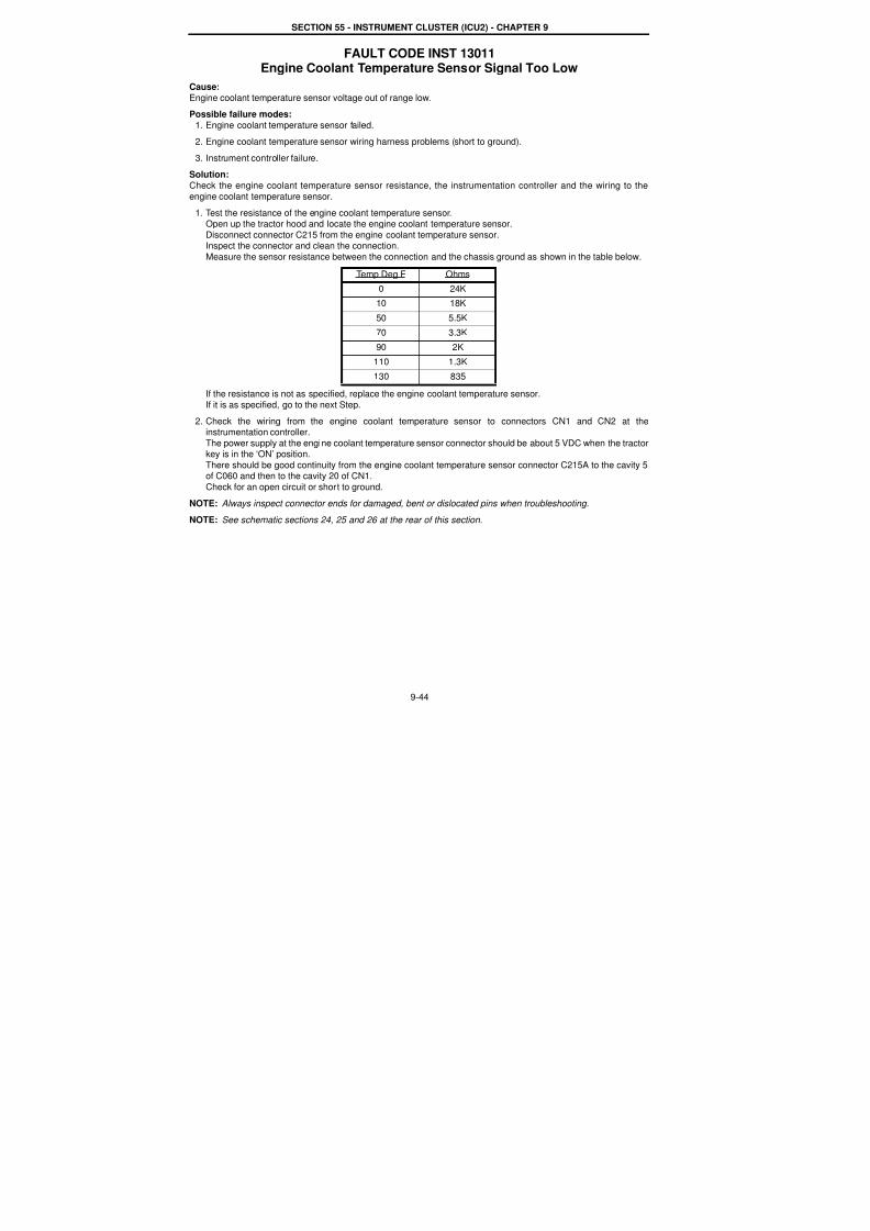
7/23/2019 Case Error Codes
http://slidepdf.com/reader/full/case-error-codes 44/140
SECTION 55 - INSTRUMENT CLUSTER (ICU2) - CHAPTER 9
9-44
FAULT CODE INST 13011Engine Coolant Temperature Sensor Signal Too Low
Cause:
Engine coolant temperature sensor voltage out of range low.
Possible failure modes:
1. Engine coolant temperature sensor failed.
2. Engine coolant temperature sensor wiring harness problems (short to ground).
3. Instrument controller failure.
Solution:
Check the engine coolant temperature sensor resistance, the instrumentation controller and the wiring to the
engine coolant temperature sensor.
1. Test the resistance of the engine coolant temperature sensor.Open up the tractor hood and locate the engine coolant temperature sensor.
Disconnect connector C215 from the engine coolant temperature sensor.Inspect the connector and clean the connection.
Measure the sensor resistance between the connection and the chassis ground as shown in the table below.
If the resistance is not as specified, replace the engine coolant temperature sensor.
If it is as specified, go to the next Step.
2. Check the wiring from the engine coolant temperature sensor to connectors CN1 and CN2 at theinstrumentation controller.
The power supply at the engine coolant temperature sensor connector should be about 5 VDC when the tractorkey is in the ‘ON’ position.
There should be good continuity from the engine coolant temperature sensor connector C215A to the cavity 5of C060 and then to the cavity 20 of CN1.
Check for an open circuit or short to ground.
NOTE: Always inspect connector ends for damaged, bent or dislocated pins when troubleshooting.
NOTE: See schematic sections 24, 25 and 26 at the rear of this section.
Temp Deg F Ohms0 24K
10 18K
50 5.5K
70 3.3K
90 2K
110 1.3K
130 835
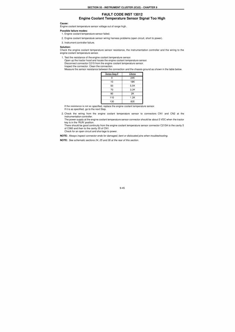
7/23/2019 Case Error Codes
http://slidepdf.com/reader/full/case-error-codes 45/140
SECTION 55 - INSTRUMENT CLUSTER (ICU2) - CHAPTER 9
9-45
FAULT CODE INST 13012Engine Coolant Temperature Sensor Signal Too High
Cause:
Engine coolant temperature sensor voltage out of range high.
Possible failure modes:
1. Engine coolant temperature sensor failed.
2. Engine coolant temperature sensor wiring harness problems (open circuit, short to power).
3. Instrument controller failure.
Solution:
Check the engine coolant temperature sensor resistance, the instrumentation controller and the wiring to the
engine coolant temperature sensor.
1. Test the resistance of the engine coolant temperature sensor.Open up the tractor hood and locate the engine coolant temperature sensor.
Disconnect connector C215 from the engine coolant temperature sensor.Inspect the connector. Clean the connection.
Measure the sensor resistance between the connection and the chassis ground as shown in the table below.
If the resistance is not as specified, replace the engine coolant temperature sensor.
If it is as specified, go to the next Step.
2. Check the wiring from the engine coolant temperature sensor to connectors CN1 and CN2 at theinstrumentation controller.
The power supply at the engine coolant temperature sensor connector should be about 5 VDC when the tractokey is in the ‘RUN’ position.
There should be good continuity from the engine coolant temperature sensor connector C215A to the cavity 5of C060 and then to the cavity 20 of CN1.
Check for an open circuit and shortage to power.
NOTE: Always inspect connector ends for damaged, bent or dislocated pins when troubleshooting.
NOTE: See schematic sections 24, 25 and 26 at the rear of this section.
Temp Deg F Ohms0 24K
10 18K
50 5.5K
70 3.3K
90 2K
110 1.3K
130 835
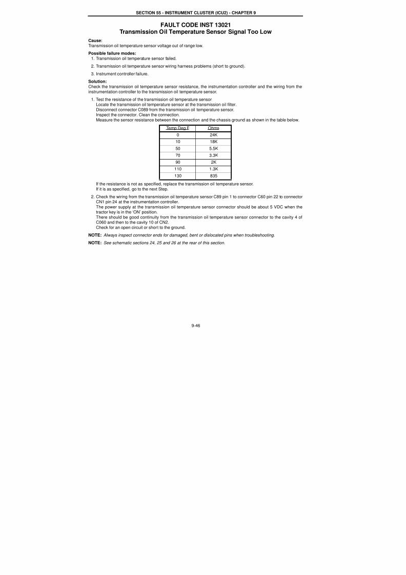
7/23/2019 Case Error Codes
http://slidepdf.com/reader/full/case-error-codes 46/140
SECTION 55 - INSTRUMENT CLUSTER (ICU2) - CHAPTER 9
9-46
FAULT CODE INST 13021Transmission Oil Temperature Sensor Signal Too Low
Cause:
Transmission oil temperature sensor voltage out of range low.
Possible failure modes:
1. Transmission oil temperature sensor failed.
2. Transmission oil temperature sensor wiring harness problems (short to ground).
3. Instrument controller failure.
Solution:
Check the transmission oil temperature sensor resistance, the instrumentation controller and the wiring from the
instrumentation controller to the transmission oil temperature sensor.
1. Test the resistance of the transmission oil temperature sensorLocate the transmission oil temperature sensor at the transmission oil filter.
Disconnect connector C089 from the transmission oil temperature sensor.Inspect the connector. Clean the connection.
Measure the sensor resistance between the connection and the chassis ground as shown in the table below.
If the resistance is not as specified, replace the transmission oil temperature sensor.
If it is as specified, go to the next Step.
2. Check the wiring from the transmission oil temperature sensor C89 pin 1 to connector C60 pin 22 to connectorCN1 pin 24 at the instrumentation controller.
The power supply at the transmission oil temperature sensor connector should be about 5 VDC when thetractor key is in the ‘ON’ position.
There should be good continuity from the transmission oil temperature sensor connector to the cavity 4 ofC060 and then to the cavity 10 of CN2.
Check for an open circuit or short to the ground.
NOTE: Always inspect connector ends for damaged, bent or dislocated pins when troubleshooting.
NOTE: See schematic sections 24, 25 and 26 at the rear of this section.
Temp Deg F Ohms0 24K
10 18K
50 5.5K
70 3.3K
90 2K
110 1.3K
130 835
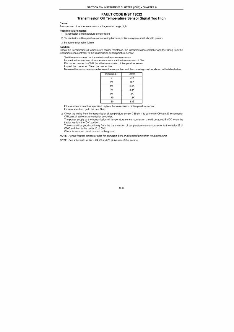
7/23/2019 Case Error Codes
http://slidepdf.com/reader/full/case-error-codes 47/140
SECTION 55 - INSTRUMENT CLUSTER (ICU2) - CHAPTER 9
9-47
FAULT CODE INST 13022Transmission Oil Temperature Sensor Signal Too High
Cause:
Transmission oil temperature sensor voltage out of range high.
Possible failure modes:
1. Transmission oil temperature sensor failed.
2. Transmission oil temperature sensor wiring harness problems (open circuit, short to power).
3. Instrument controller failure.
Solution:
Check the transmission oil temperature sensor resistance, the instrumentation controller and the wiring from the
instrumentation controller to the transmission oil temperature sensor.
1. Test the resistance of the transmission oil temperature sensor.Locate the transmission oil temperature sensor at the transmission oil filter.
Disconnect connector C089 from the transmission oil temperature sensor.Inspect the connector. Clean the connection.
Measure the sensor resistance between the connection and the chassis ground as shown in the table below.
If the resistance is not as specified, replace the transmission oil temperature sensor.
If it is as specified, go to the next Step.
2. Check the wiring from the transmission oil temperature sensor C89 pin 1 to connector C60 pin 22 to connectoCN1, pin 24 at the instrumentation controller.
The power supply at the transmission oil temperature sensor connector should be about 5 VDC when thetractor key is in the ‘ON’ position.
There should be good continuity from the transmission oil temperature sensor connector to the cavity 22 oC060 and then to the cavity 10 of CN2.
Check for an open circuit or short to the ground.
NOTE: Always inspect connector ends for damaged, bent or dislocated pins when troubleshooting.
NOTE: See schematic sections 24, 25 and 26 at the rear of this section.
Temp Deg F Ohms0 24K
10 18K
50 5.5K
70 3.3K
90 2K
110 1.3K
130 835

7/23/2019 Case Error Codes
http://slidepdf.com/reader/full/case-error-codes 48/140
SECTION 55 - INSTRUMENT CLUSTER (ICU2) - CHAPTER 9
9-48
FAULT CODE INST 13044Short is Detected as Fuel Shutoff Relay is Latched
(Mechanical Engine Only)
Cause:When fuel shut-off is latched, greater than 500 milliamp current draw was sensed at fuel relay solenoid Pin 13,
connector CN2 on instrument cluster. This fault code may be generated during a Level 1 critical warning for very
high engine intake air to air temperature, very high engine coolant temperature , very low engine oil pressure, orvery high transmission oil temperature.
Possible failure modes:
1. Possible short circuit in Wire 602(W) beteween Conector CN2, pin 13 and fuel shutoff relay pin 2.
2. Defective fuel shutoff relay.
Solution:
1. Check for short circuit in wire 602(W) from connector CN2, pin 13 to connector 60M, pin 14, to connector 333F,
pin 8, to connector 7M, pin B, to fuel shutoff relay, pin 2.
2. Replace fuel shutoff relay with known good relay.
NOTE: Always inspect connector ends for damaged, bent or dislocated pins when troubleshooting.
NOTE: See schematic sections 19 through 24 at the rear of this section.

7/23/2019 Case Error Codes
http://slidepdf.com/reader/full/case-error-codes 49/140
SECTION 55 - INSTRUMENT CLUSTER (ICU2) - CHAPTER 9
9-49
FAULT CODE INST 13051Air To Air Intake Temperature Sensor Signal Too Low
Cause:
Air to air intake temperature sensor voltage out of range low.
Possible failure modes:
1. Air to air intake oil temperature sensor failed.
2. Air to air intake oil temperature sensor wiring harness problems (short to ground).
3. Instrument controller failure.
Solution:
Check the air to air intake temperature sensor resistance, the instrumentation controller and the wiring from theinstrumentation controller to the air to air intake temperature sensor.
1. Test the resistance of the air to air intake temperature sensor.
Open the tractor hood and locate the air to air intake temperature sensor.
Disconnect connector C075 from the air to air intake temperature sensor.Inspect pin A and B in the connector. Clean the connection. Clean the mating pin and the connector.
Use the table below and measure the sensor resistance between pin A and pin B.
If the resistance is not as specified, replace the air to air intake temperature sensor.If it is as specified, go to the next Step.
2. Check the wiring from the air intake temperature sensor to connectors CN1 and CN2 at the instrumentationcontroller.The power supply at the pin A of the air to air intake temperature sensor connector should be about 5 VDC
when the tractor key is in the ‘ON’ position.
There should be good continuity from pin A of C075 to pin 8 of connector C334 to cavity 26 of connector C060and then to cavity 21 of connector CN1.
There should be good continuity between pin B of C075 and the clean ground.Check for open circuit and shortage to ground.
NOTE: Always inspect connector ends for damaged, bent or dislocated pins when troubleshooting.
NOTE: See schematic sections 24, 25 and 26 at the rear of this section.
Temp Deg C Ohms
0 32650
5 25390
10 19900
15 15710
20 12940
25 1000
30 8057
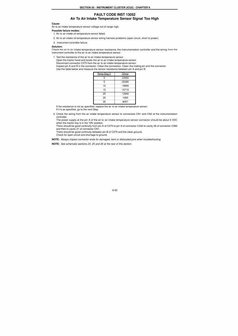
7/23/2019 Case Error Codes
http://slidepdf.com/reader/full/case-error-codes 50/140
SECTION 55 - INSTRUMENT CLUSTER (ICU2) - CHAPTER 9
9-50
FAULT CODE INST 13052Air To Air Intake Temperature Sensor Signal Too High
Cause:
Air to air intake temperature sensor voltage out of range high.
Possible failure modes:
1. Air to air intake oil temperature sensor failed.
2. Air to air intake oil temperature sensor wiring harness problems (open circuit, short to power).
3. .Instrument controller failure.
Solution:
Check the air to air intake temperature sensor resistance, the instrumentation controller and the wiring from theinstrument controller to the air to air intake temperature sensor.
1. Test the resistance of the air to air intake temperature sensor.
Open the tractor hood and locate the air to air intake temperature sensor.
Disconnect connector C075 from the air to air intake temperature sensor.Inspect pin A and B in the connector. Clean the connection. Clean the mating pin and the connector.
Use the table below and measure the sensor resistance between pin A and pin B.
If the resistance is not as specified, replace the air to air intake temperature sensor.If it is as specified, go to the next Step.
2. Check the wiring from the air intake temperature sensor to connectors CN1 and CN2 at the instrumentationcontroller.The power supply at the pin A of the air to air intake temperature sensor connector should be about 5 VDC
when the tractor key is in the ‘ON’ position.
There should be good continuity from pin A of C075 to pin 8 of connector C334 to cavity 26 of connector C060and then to cavity 21 of connector CN1.
There should be good continuity between pin B of C075 and the clean ground.Check for open circuit and shortage to ground.
NOTE: Always inspect connector ends for damaged, bent or dislocated pins when troubleshooting.
NOTE: See schematic sections 24, 25 and 26 at the rear of this section.
Temp Deg C Ohms
0 32650
5 25390
10 19900
15 15710
20 12940
25 1000
30 8057

7/23/2019 Case Error Codes
http://slidepdf.com/reader/full/case-error-codes 51/140
SECTION 55 - INSTRUMENT CLUSTER (ICU2) - CHAPTER 9
9-51
FAULT CODE INST 53005Engine Shutdown activated by ICU2 Controller
Causec
This fault code is generated by the instrument cluster due to a Level 1 Critical Warning. The Instrument Clustesignaled very high engine intake air to air temperature, very high engine coolant temperature, very low engine oi
pressure or very high transmission oil temperature.
Possible failure modes:1. Very High Engine Coolant Temperature
2. Very Low Engine Oil Pressure
3. Very High Engine Intake Air to Air Temperature
4. Very High Transmission Oil Temperature
Solution:This fault code is recorded each time a Level 1 Critical Warning automatic engine shutdown has been activated.
1. Shut the tractor engine OFF immediately and check coolant level or radiator for blockage or other cause.
2. Shut the tractor engine OFF immediately and check oil level or other cause.
3. Shut the tractor engine OFF immediately and check the heat exchanger for blockage.
4. Shut the tractor engine OFF immediately and check for blocked cooler or other cause.
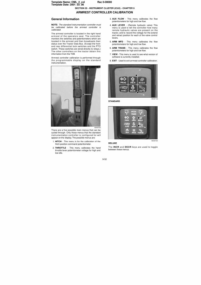
7/23/2019 Case Error Codes
http://slidepdf.com/reader/full/case-error-codes 52/140
9-52
Template Name: OML_2_col Rac 0-00000Template Date: 2001_03_06
SECTION 55 - INSTRUMENT CLUSTER (ICU2) - CHAPTER 9
ARMREST CONTROLLER CALIBRATION
General Information
NOTE: The standard instrumentation controller must
be calibrated before the armrest controller is calibrated.
The armrest controller is located in the right hand
armrest of the operators seat. The controllermonitors the switches and potentiometers which are
located in the armrest and then broadcasts theirstatus over the Tractor Data Bus. (Except the front
and rear differential lock switches and the PTO
switch. These switches are wired directly to relays.)
The other controllers on the tractor obtain this
information from the TDB.
Armrest controller calibration is performed through
the programmable d isp lay on the s tandard
instrumentation.
MD05F002
There are a five possible main menus that can becycled through. Only those menus that the standard
instrumentation controller is configured for will
appear on the display. The possible menus are:
1. HITCH - This menu is for the calibration of the
hitch position command potentiometer.
2. THROTTLE - This menu calibrates the handthrottle lever potentiometer voltage for high and
low idle.
3. AUX FLOW - This menu calibrates the flowpotentiometers for high and low flow.
4. AUX LEVER - (Remote hydraulic valve) This
menu is used to tell the controller how manyremote hydraulic valves are present on the
tractor, and to record the voltage for the extendand retract position for each of the valve contro
levers.
5. ARM MFD - This menu calibrates the flowpotentiometers for high and low flow.
6. ARM TRANS - This menu calibrates the flow
potentiometers for high and low flow.
7. VIEW - This menu is used to see what version osoftware is currently installed.
8. EXIT - Used to exit armrest controller calibration
MD05F18
STANDARD
MD05F00
DELUXE
The INCR and DECR keys are used to togglebetween these menus.
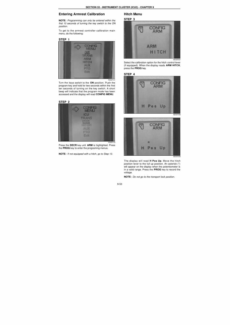
7/23/2019 Case Error Codes
http://slidepdf.com/reader/full/case-error-codes 53/140
SECTION 55 - INSTRUMENT CLUSTER (ICU2) - CHAPTER 9
9-53
Entering Armrest Calibration
NOTE: Programming can only be entered within the
first 10 seconds of turning the key switch to the ON
position.
To get to the armrest controller calibration main
menu, do the following:
STEP 1
RD05F101
Turn the keys switch to the ON position. Push theprogram key and hold for two seconds within the first
ten seconds of turning on the key switch. A short
beep will indicate that the program mode has beenaccessed and the display will read CONFIG MENU.
STEP 2
RD05F143
Press the DECR key until ARM is highlighted. Press
the PROG key to enter the programing menus.
NOTE: If not equipped with a hitch, go to Step 13.
Hitch Menu
STEP 3
MD05F09
Select the calibration option for the hitch control leve(if equipped). When the display reads ARM HITCH
press the PROG key.
STEP 4
MD05F09
MD05F09
The display will read H Pos Up. Move the hitch
position lever to the full up position. An asterisk (*)
will appear on the display when the potentiometer isin a valid range. Press the PROG key to record the
voltage.
NOTE: Do not go to the transport lock position.
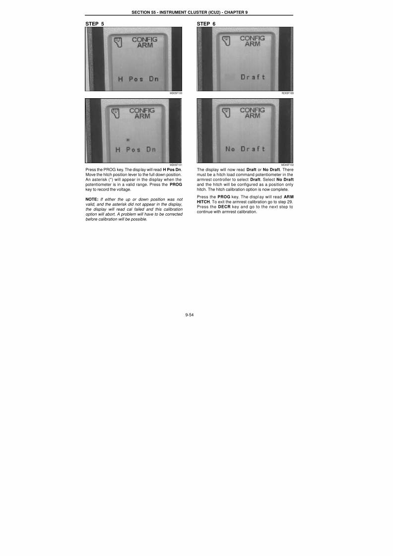
7/23/2019 Case Error Codes
http://slidepdf.com/reader/full/case-error-codes 54/140
SECTION 55 - INSTRUMENT CLUSTER (ICU2) - CHAPTER 9
9-54
STEP 5
MD05F100
MD05F101
Press the PROG key. The display will read H Pos Dn.
Move the hitch position lever to the full down position.An asterisk (*) will appear in the display when the
potentiometer is in a valid range. Press the PROG
key to record the voltage.
NOTE: If either the up or down position was not valid, and the asterisk did not appear in the display,
the display will read cal failed and this calibration option will abort. A problem will have to be corrected
before calibration will be possible.
STEP 6
RD05F189
MD05F102
The display will now read Draft or No Draft. There
must be a hitch load command potentiometer in thearmrest controller to select Draft. Select No Draft
and the hitch will be configured as a position only
hitch. The hitch calibration option is now complete.
Press the PROG key. The display will read ARM
HITCH. To exit the armrest calibration go to step 29.Press the DECR key and go to the next step to
continue with armrest calibration.
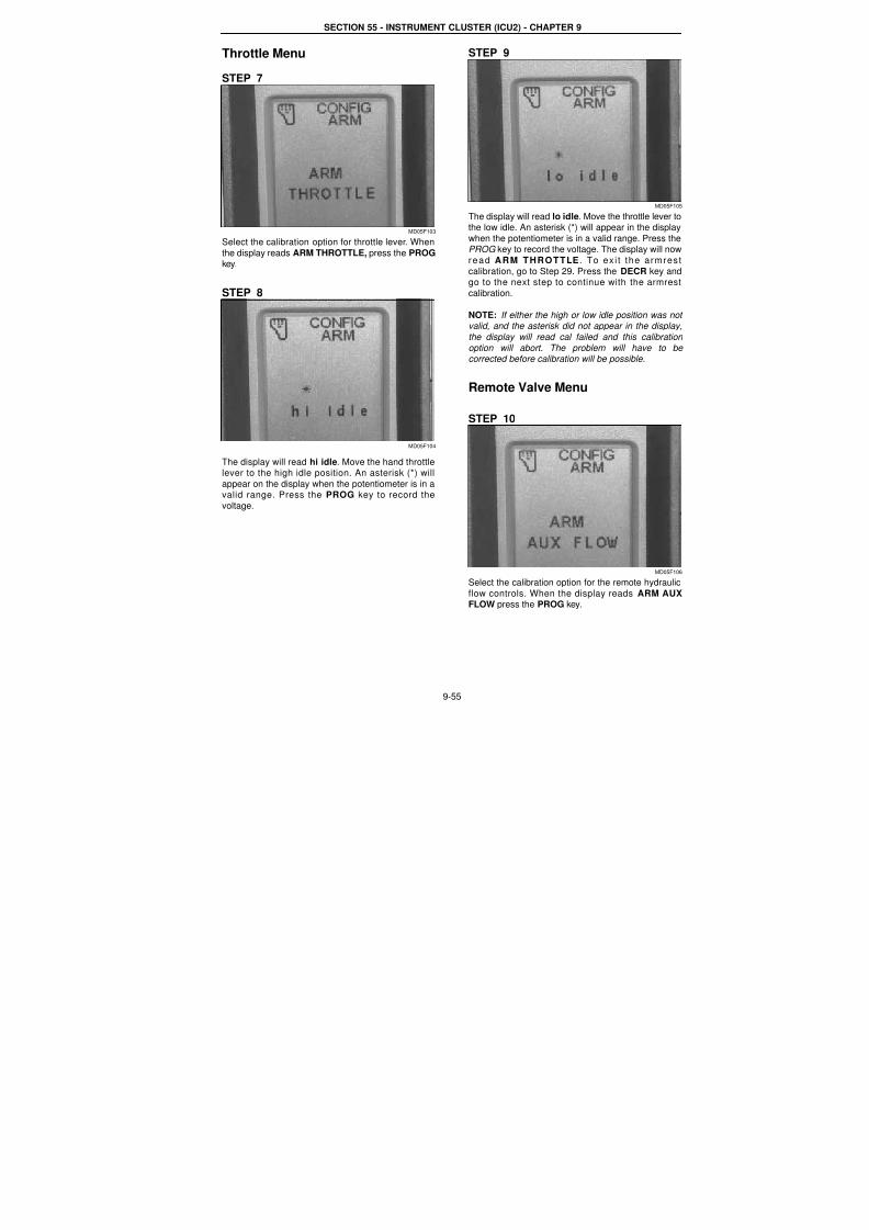
7/23/2019 Case Error Codes
http://slidepdf.com/reader/full/case-error-codes 55/140
SECTION 55 - INSTRUMENT CLUSTER (ICU2) - CHAPTER 9
9-55
Throttle Menu
STEP 7
MD05F103
Select the calibration option for throttle lever. When
the display reads ARM THROTTLE, press the PROGkey.
STEP 8
MD05F104
The display will read hi idle. Move the hand throttlelever to the high idle position. An asterisk (*) will
appear on the display when the potentiometer is in avalid range. Press the PROG key to record the
voltage.
STEP 9
MD05F10
The display will read lo idle. Move the throttle lever tothe low idle. An asterisk (*) will appear in the display
when the potentiometer is in a valid range. Press thePROG key to record the voltage. The display will now
read ARM THROTTLE . To ex i t the armres
calibration, go to Step 29. Press the DECR key andgo to the next step to continue with the armres
calibration.
NOTE: If either the high or low idle position was novalid, and the asterisk did not appear in the display
the display will read cal failed and this calibration
option will abort. The problem will have to becorrected before calibration will be possible.
Remote Valve Menu
STEP 10
MD05F10
Select the calibration option for the remote hydraulic
flow controls. When the display reads ARM AUXFLOW press the PROG key.
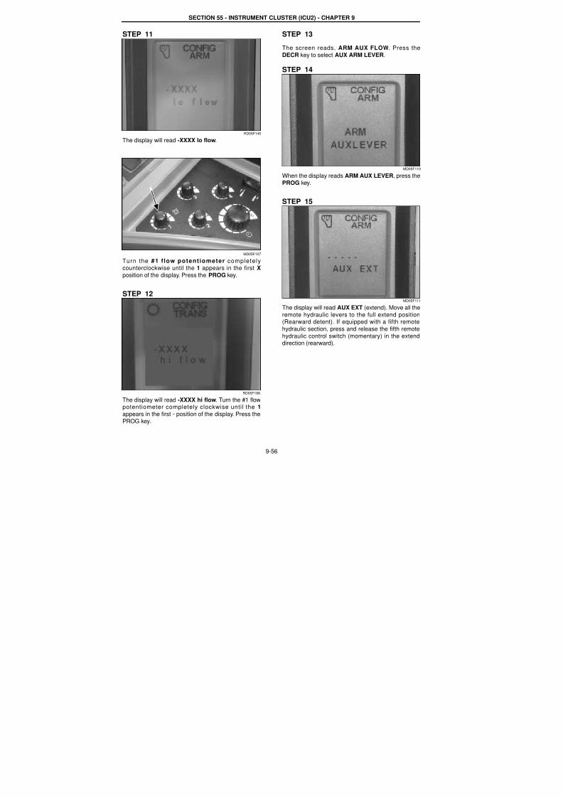
7/23/2019 Case Error Codes
http://slidepdf.com/reader/full/case-error-codes 56/140
SECTION 55 - INSTRUMENT CLUSTER (ICU2) - CHAPTER 9
9-56
STEP 11
RD05F145
The display will read -XXXX lo flow.
MD05F107
Turn the #1 f low potentiometer completely
counterclockwise until the 1 appears in the first Xposition of the display. Press the PROG key.
STEP 12
RD05F188.
The display will read -XXXX hi flow. Turn the #1 flowpotentiometer completely clockwise until the 1
appears in the first - position of the display. Press the
PROG key.
STEP 13
The screen reads, ARM AUX FLOW. Press the
DECR key to select AUX ARM LEVER.
STEP 14
MD05F110
When the display reads ARM AUX LEVER, press thePROG key.
STEP 15
MD05F111
The display will read AUX EXT (extend). Move all the
remote hydraulic levers to the full extend position(Rearward detent). If equipped with a fifth remote
hydraulic section, press and release the fifth remote
hydraulic control switch (momentary) in the extenddirection (rearward).
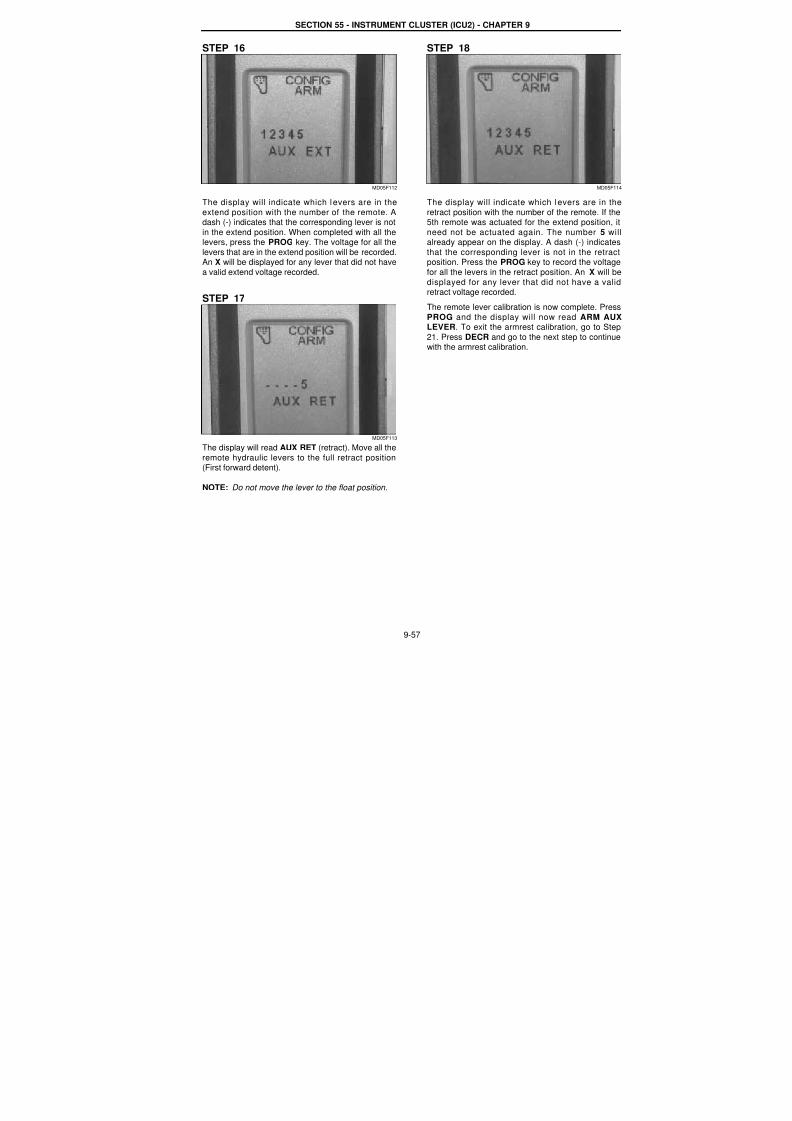
7/23/2019 Case Error Codes
http://slidepdf.com/reader/full/case-error-codes 57/140
SECTION 55 - INSTRUMENT CLUSTER (ICU2) - CHAPTER 9
9-57
STEP 16
MD05F112
The display will indicate which l evers are in the
extend position with the number of the remote. Adash (-) indicates that the corresponding lever is not
in the extend position. When completed with all thelevers, press the PROG key. The voltage for all the
levers that are in the extend position will be recorded.An X will be displayed for any lever that did not have
a valid extend voltage recorded.
STEP 17
MD05F113
The display will read AUX RET (retract). Move all the
remote hydraulic levers to the full retract position(First forward detent).
NOTE: Do not move the lever to the float position.
STEP 18
MD05F11
The display will indicate which l evers are in the
retract position with the number of the remote. If the5th remote was actuated for the extend position, it
need not be actuated again. The number 5 wilalready appear on the display. A dash (-) indicates
that the corresponding lever is not in the retractposition. Press the PROG key to record the voltage
for all the levers in the retract position. An X will be
displayed for any lever that did not have a validretract voltage recorded.
The remote lever calibration is now complete. Press
PROG and the display will now read ARM AUXLEVER. To exit the armrest calibration, go to Step
21. Press DECR and go to the next step to continuewith the armrest calibration.

7/23/2019 Case Error Codes
http://slidepdf.com/reader/full/case-error-codes 58/140
SECTION 55 - INSTRUMENT CLUSTER (ICU2) - CHAPTER 9
9-58
ARM MFD
STEP 19
RD05F147
RD05F148
Select the software view option from the main menu.
The display will read ARM MFD. Press the PROGkey. The display will read YES MFD ? Press theINCR key to change to NO MFD ? if not equipped.Press the PROG ket to exit the ARM MFD menu.
ARM TRANS
STEP 20
RD05F151
RD05F153
Select the software view option from the main menu.
The display will read ARM TRANS. Press the PROGkey. The display will read YES Creeper ? Press theINCR key to change to NO Creeper ? i f notequipped. Press the PROG ket to exit the ARM
TRANS menu.
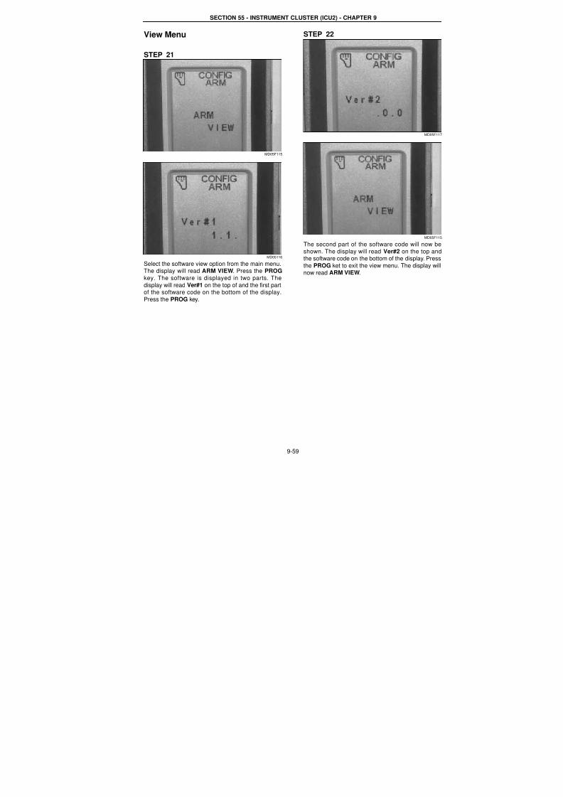
7/23/2019 Case Error Codes
http://slidepdf.com/reader/full/case-error-codes 59/140
SECTION 55 - INSTRUMENT CLUSTER (ICU2) - CHAPTER 9
9-59
View Menu
STEP 21
MD05F115
MD05116
Select the software view option from the main menu.
The display will read ARM VIEW. Press the PROGkey. The software is displayed in two parts. The
display will read Ver#1 on the top of and the first partof the software code on the bottom of the display.
Press the PROG key.
STEP 22
MD05F11
MD05F11
The second part of the software code will now be
shown. The display will read Ver#2 on the top andthe software code on the bottom of the display. Press
the PROG ket to exit the view menu. The display wil
now read ARM VIEW.

7/23/2019 Case Error Codes
http://slidepdf.com/reader/full/case-error-codes 60/140
SECTION 55 - INSTRUMENT CLUSTER (ICU2) - CHAPTER 9
9-60
Exit Calibration
STEP 23
MD05F118
Use the DECR key to select the ARM EXIT menu
and press the PROG key to exit armrest controllercalibration. The display will now read CONFIG
MENU. Press the INCR or DECR key until the displayreads EXIT SET MENU. Press the PROG key to
return to normal operation.
7/23/2019 Case Error Codes
http://slidepdf.com/reader/full/case-error-codes 61/140
9-61
Template Name: OML_2_col Rac 0-00000Template Date: 2001_03_06
SECTION 55 - INSTRUMENT CLUSTER (ICU2) - CHAPTER 9
ARMREST CONTROLLER FAULT CODES
FAULT CODE ARM 1019Transmission Gear Selection Switch Failure
Cause:
This fault code is triggered when up shift and down shift switches are detected to be closed at the same time.
Possible failure modes:
1. Switch failed.2. External wiring failure (damaged wires, loose connectors, or bent pins).
3. Armrest controller internal failure (power supply or signal sensing failed).
Solution:
Test the switch function, wiring, and the function of the armrest controller.
NOTE: The transmission gear selection switch information is broadcast over the Data Bus. The transmission gear
selection switch can be monitored using the MONITOR window in the service tool and selecting Armrest TransShift Switch - Shift Down and Armrest Trans Shift Switch - Shift Up.
1. Open the armrest controller housing and disconnect connector J211.
2. Test the transmission gear selection switch and its wiring. Pay attention to wiring damage, loose connectors, o
bent pins.a. When the switch is in SHIFT UP position, there should be continuity between pin 1 and pin 2 and no
continuity between pin 1 and pin 3.b. When the switch is in SHIFT DOWN position, there should be continuity between pin 1 and pin 3 and no
continuity between pin 1 and pin 2.
c. When the switch is in OFF position, there should be no continuity between any two of pin 1, pin 2, and pin 3If the switch is not functioning as specified above, replace the switch.
3. Check controller function:
a. Cycle the key switch to OFF, then to the ON position. Measure the voltage output from the controller at pin 1of J211. It should be approximately 12 volts.
b. Short pin 1 to pin 2 to simulate the shift up function. Short pin 1 to pin 3 to simulate the shift down function.
Monitor the switch status on the monitor screen of the service tool.If the controller does not function properly, replace the armrest controller.
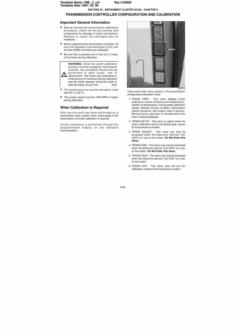
7/23/2019 Case Error Codes
http://slidepdf.com/reader/full/case-error-codes 62/140
9-62
Template Name: OML_2_col Rac 0-00000Template Date: 2001_03_06
SECTION 55 - INSTRUMENT CLUSTER (ICU2) - CHAPTER 9
TRANSMISSION CONTROLLER CONFIGURATION AND CALIBRATION
Important General Information
• Before starting the transmission calibrationprocedure, check the wir ing harness and
components for damage or loose connections.
Rep lace or repa i r any damaged par t asnecessary.
• Before calibrating the transmission controller, be
sure the Standard Instrumentation (ICU) andArmrest (ARM) controllers are calibrated.
• Be sure that no persons are in front of or in back
of the tractor during calibration.
• The transmission oil must be warmed to morethan 60°C (140°F).
• The engine speed must be 1200 RPM or higher
during calibration.
When Calibration is Required
After service work has been performed on atransmission valve, master clutch, clutch pedal or thetransmission controller calibration is required.
Clutch cal ibrat ion is per formed through the
programmable d isp lay on the s tandard
instrumentation.
MD05F00
There are 6 main menu options in the transmission
configuration/calibration mode:
1. TRANS VIEW - This menu displays clutchcalibration values (milliamp and temperature)
System oil temperature, inching pedal calibrationvalues, software revision numbers, transmission
system pressure, and engine load in percent
Normal tractor operation is allowed while thismenu is being displayed.
2. TRANS SETUP - This menu is used to enter theclutch calibration and to set default gear values
for transmission controller.
3. TRANS ADJUST - This menu can only beaccessed when the Electronic Service Too
(EST) is in use on the tractor. Do Not Enter thismenu.
4. TRANS DIAG - This menu can only be accessed
when the Electronic Service Tool (EST) is in use
on the tractor. Do Not Enter this menu.5. TRANS FSUS - This menu can only be accessed
when the Electronic Service Tool (EST) is in use
on the tractor.
6. TRANS EXIT - This menu entry will exit the
calibration mode for the transmission system.
WARNING: Since the clutch calibration process involves engaging transmission
clutches, this procedure should only be per fo rmed in open areas , f ree o f
obstructions. The tractor may experience a small amount of movement during calibration and the tractor operator should be ready to
stop the tractor at any time. M588
!
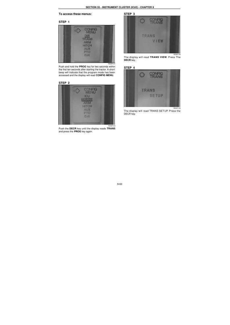
7/23/2019 Case Error Codes
http://slidepdf.com/reader/full/case-error-codes 63/140
SECTION 55 - INSTRUMENT CLUSTER (ICU2) - CHAPTER 9
9-63
To access these menus:
STEP 1
RD05F101
Push and hold the PROG key for two seconds withinthe first ten seconds after starting the tractor. A short
beep will indicate that the program mode has beenaccessed and the display will read CONFIG MENU.
STEP 2
RD05F103
Push the DECR key until the display reads TRANS
and press the PROG key again.
STEP 3
RD05F10
The display will read TRANS VIEW. Press TheDECR key.
STEP 4
RD05F12
The display will read TRANS SETUP. Press theDECR key.
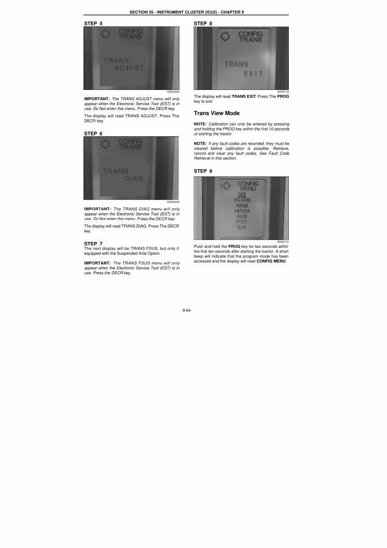
7/23/2019 Case Error Codes
http://slidepdf.com/reader/full/case-error-codes 64/140
SECTION 55 - INSTRUMENT CLUSTER (ICU2) - CHAPTER 9
9-64
STEP 5
RD05G004
IMPORTANT: The TRANS ADJUST menu will only
appear when the Electronic Service Tool (EST) is in use. Do Not enter this menu. Press the DECR key.
The display will read TRANS ADJUST. Press The
DECR key.
STEP 6
RD05G006
IMPORTANT: The TRANS DIAG menu will only
appear when the Electronic Service Tool (EST) is in use. Do Not enter this menu. Press the DECR key.
The display will read TRANS DIAG. Press The DECR
key.
STEP 7The next display will be TRANS FSUS, but only ifequipped with the Suspended Axle Option.
IMPORTANT: The TRANS FSUS menu will only
appear when the Electronic Service Tool (EST) is in
use. Press the DECR key.
STEP 8
RD05F134
The display will read TRANS EXIT. Press The PROGkey to exit.
Trans View Mode
NOTE: Calibration can only be entered by pressing and holding the PROG key within the first 10 seconds of starting the tractor.
NOTE: If any fault codes are recorded, they must be
cleared before calibration is possible. Retrieve,
record and clear any fault codes. See Fault Code Retrieval in this section.
STEP 9
RD05F101
Push and hold the PROG key for two seconds withinthe first ten seconds after starting the tractor. A short
beep will indicate that the program mode has beenaccessed and the display will read CONFIG MENU.
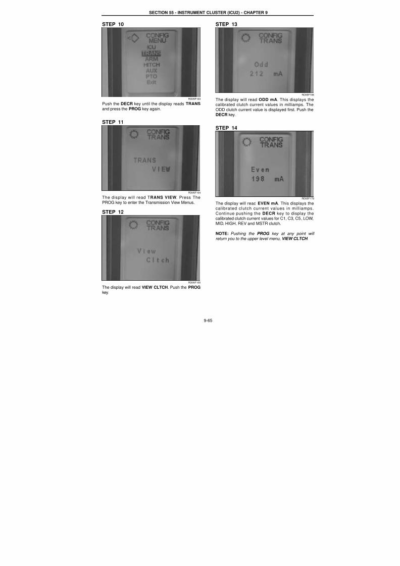
7/23/2019 Case Error Codes
http://slidepdf.com/reader/full/case-error-codes 65/140
SECTION 55 - INSTRUMENT CLUSTER (ICU2) - CHAPTER 9
9-65
STEP 10
RD05F103
Push the DECR key until the display reads TRANS
and press the PROG key again.
STEP 11
RD05F104
The display will read TRANS VIEW. Press The
PROG key to enter the Transmission View Menus.
STEP 12
RD05F105
The display will read VIEW CLTCH. Push the PROG
key.
STEP 13
RD05F10
The display will read ODD mA. This displays thecalibrated clutch current values in milliamps. The
ODD clutch current value is displayed first. Push theDECR key.
STEP 14
RD05F17
The display will read EVEN mA. This displays thecalibrated clutch current values in mill iamps
Continue pushing the DECR key to display thecalibrated clutch current values for C1, C3, C5, LOW
MID, HIGH, REV and MSTR clutch.
NOTE: Pushing the PROG key at any point wil
return you to the upper level menu, VIEW CLTCH .

7/23/2019 Case Error Codes
http://slidepdf.com/reader/full/case-error-codes 66/140
SECTION 55 - INSTRUMENT CLUSTER (ICU2) - CHAPTER 9
9-66
STEP 15
RD05F107
The Master Clutch milliamp reading is the finalreadout. Push the PROG key.
NOTE: If you continue to push the DECR key the
display will start through the menu again starting with
the ODD clutch mA reading.
STEP 16
RD05F105
The display will return to VIEW CLTCH. To displaythe next Transmission View Menu push the DECR
key.
STEP 17
RD05F108
The d isp lay wi l l read CAL C LTCHTMP. TheCalibration Clutch Temperature View Menu shows
the clutch temp at which the cal ibrat ion wasperformed. Push the PROG key.
STEP 18
RD05F109
The display will read ODD DEGC. The CalibrationClutch Temperature View Menu shows the clutch
temp at which the calibration was performed. Pushthe DECR key.
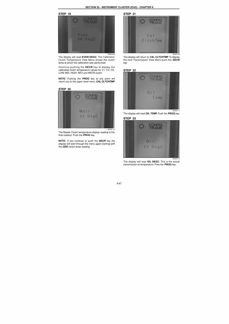
7/23/2019 Case Error Codes
http://slidepdf.com/reader/full/case-error-codes 67/140
SECTION 55 - INSTRUMENT CLUSTER (ICU2) - CHAPTER 9
9-67
STEP 19
RD05G008
The display will read EVEN DEGC. The CalibrationClutch Temperature View Menu shows the clutch
temp at which the calibration was performed.
Continue pushing the DECR key to display thecalibrated clutch temperature values for C1, C3, C5,
LOW, MID, HIGH, REV and MSTR clutch.
NOTE: Pushing the PROG key at any point will
return you to the upper level menu, CAL CLTCHTMP .
STEP 20
RD05F110
The Master Clutch temperature display reading is thefinal readout. Push the PROG key.
NOTE: If you continue to push the DECR key the
display will start through the menu again starting with
the ODD clutch temp reading.
STEP 21
RD05F10
The display will return to CAL CLTCHTMP. To displaythe next Transmission View Menu push the DECR
key.
STEP 22
RD05F11
The display will read OIL TEMP. Push the PROG key
STEP 23
RD05F11
The display will read OIL DEGC. This is the actuatransmission oil temperature. Pres the PROG key.

7/23/2019 Case Error Codes
http://slidepdf.com/reader/full/case-error-codes 68/140
SECTION 55 - INSTRUMENT CLUSTER (ICU2) - CHAPTER 9
9-68
STEP 24
RD05F111
The display returns to OIL TEMP display. To displaythe next Transmission View Menu push the DECR
key.
STEP 25
RD05F113
The display will read VIEW PEDAL. The Clutch
Pedal View Menu displays the position of the clutch.Push the PROG key.
STEP 26
RD05F114
The current pedal position is displayed, 100% for
inching pedal up (top of clutch). Depress the inching
pedal to the floor.
STEP 27
RD05F115
The display will read 0% for inching pedal to the floor(bottom of clutch). Release pedal and push the
PROG key.
STEP 28
RD05F113
The display will again read VIEW PEDAL. To display
the next Transmission View Menu push the DECRkey.
STEP 29
RD05F116
The display will read SW REVISION. This is the
Software Revision View Menu. Push the PROG key.
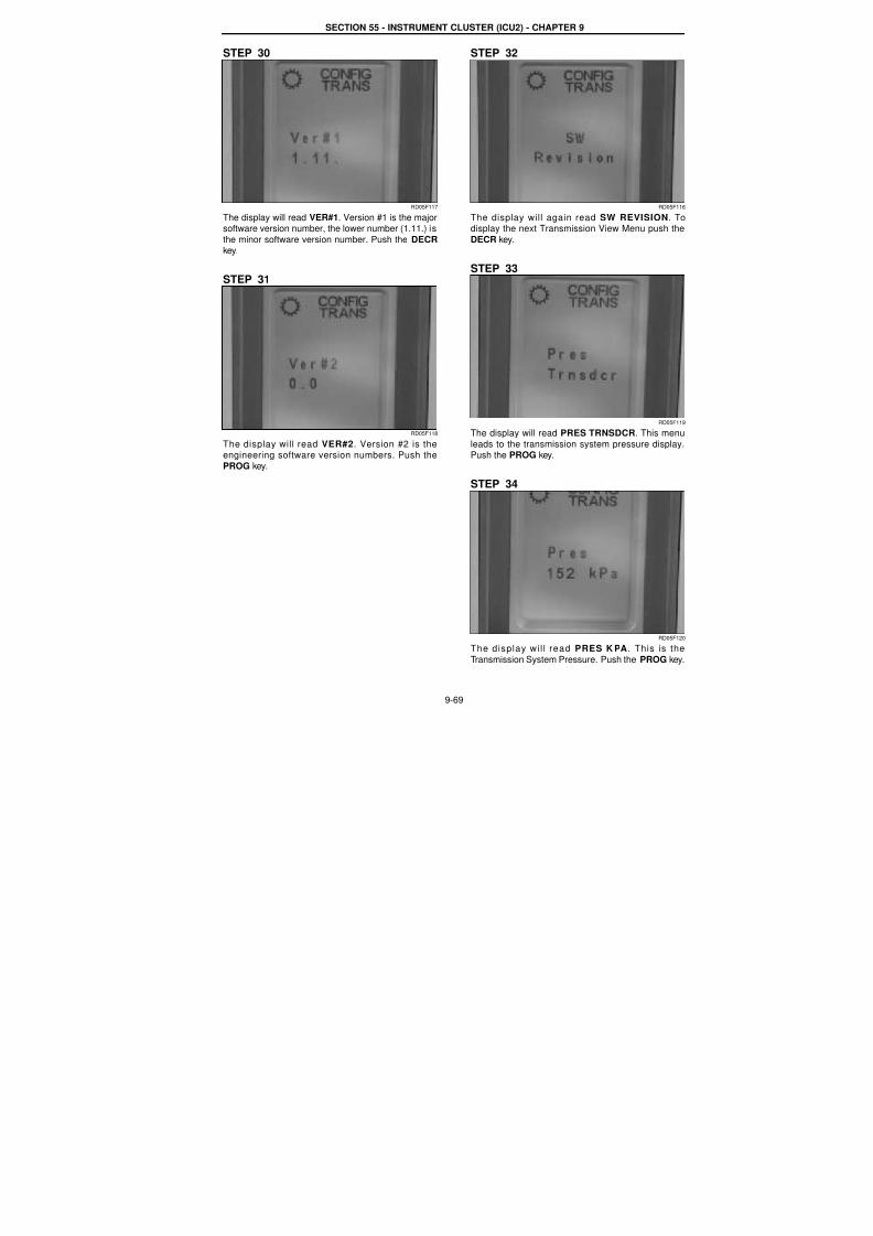
7/23/2019 Case Error Codes
http://slidepdf.com/reader/full/case-error-codes 69/140
SECTION 55 - INSTRUMENT CLUSTER (ICU2) - CHAPTER 9
9-69
STEP 30
RD05F117
The display will read VER#1. Version #1 is the majorsoftware version number, the lower number (1.11.) is
the minor software version number. Push the DECRkey.
STEP 31
RD05F118
The display will read VER#2. Version #2 is theengineering software version numbers. Push the
PROG key.
STEP 32
RD05F11
The display will again read SW REVISION. Todisplay the next Transmission View Menu push the
DECR key.
STEP 33
RD05F11
The display will read PRES TRNSDCR. This menu
leads to the transmission system pressure displayPush the PROG key.
STEP 34
RD05F12
The display wil l read PRES K PA . This is the
Transmission System Pressure. Push the PROG key
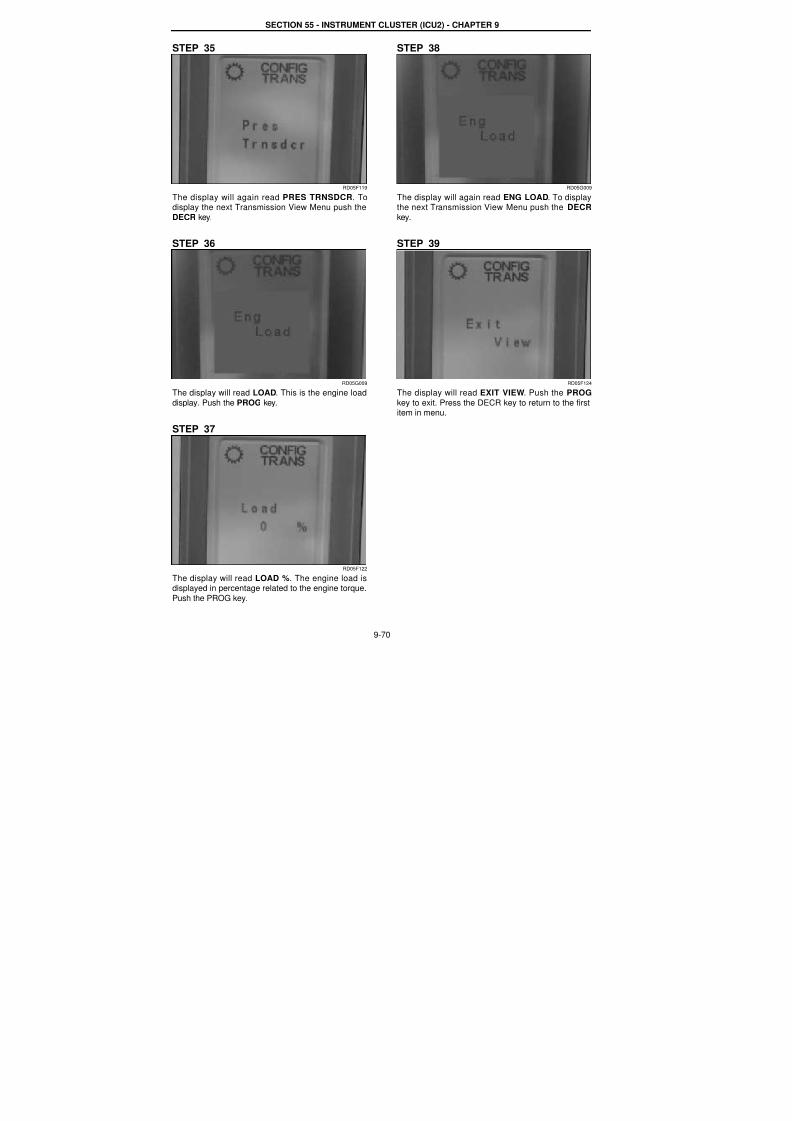
7/23/2019 Case Error Codes
http://slidepdf.com/reader/full/case-error-codes 70/140
SECTION 55 - INSTRUMENT CLUSTER (ICU2) - CHAPTER 9
9-70
STEP 35
RD05F119
The display will again read PRES TRNSDCR. Todisplay the next Transmission View Menu push the
DECR key.
STEP 36
RD05G009
The display will read LOAD. This is the engine load
display. Push the PROG key.
STEP 37
RD05F122
The display will read LOAD %. The engine load isdisplayed in percentage related to the engine torque.
Push the PROG key.
STEP 38
RD05G009
The display will again read ENG LOAD. To displaythe next Transmission View Menu push the DECR
key.
STEP 39
RD05F124
The display will read EXIT VIEW. Push the PROG
key to exit. Press the DECR key to return to the firstitem in menu.
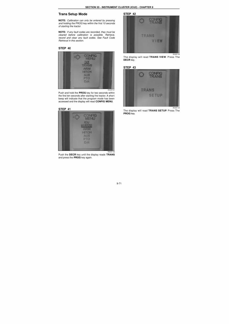
7/23/2019 Case Error Codes
http://slidepdf.com/reader/full/case-error-codes 71/140
SECTION 55 - INSTRUMENT CLUSTER (ICU2) - CHAPTER 9
9-71
Trans Setup Mode
NOTE: Calibration can only be entered by pressing
and holding the PROG key within the first 10 seconds
of starting the tractor.
NOTE: If any fault codes are recorded, they must be cleared before calibration is possible. Retrieve,
record and clear any fault codes. See Fault Code Retrieval in this section.
STEP 40
RD05F101
Push and hold the PROG key for two seconds within
the first ten seconds after starting the tractor. A shortbeep will indicate that the program mode has been
accessed and the display will read CONFIG MENU.
STEP 41
RD05F103
Push the DECR key until the display reads TRANS
and press the PROG key again.
STEP 42
RD05F10
The display will read TRANS VIEW. Press TheDECR key.
STEP 43
RD05F12
The display will read TRANS SETUP. Press ThePROG key.
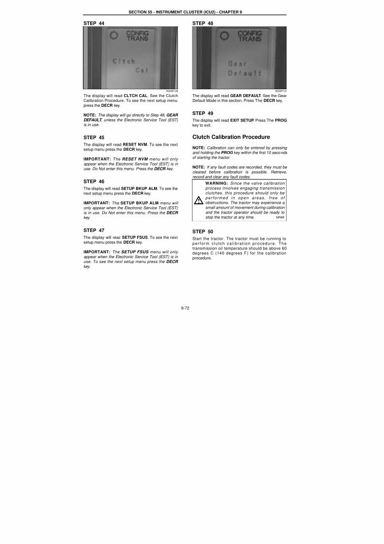
7/23/2019 Case Error Codes
http://slidepdf.com/reader/full/case-error-codes 72/140
SECTION 55 - INSTRUMENT CLUSTER (ICU2) - CHAPTER 9
9-72
STEP 44
RD05F126
The display will read CLTCH CAL. See the ClutchCalibration Procedure. To see the next setup menu
press the DECR key.
NOTE: The display will go directly to Step 48, GEAR
DEFAULT , unless the Electronic Service Tool (EST)is in use.
STEP 45
The display will read RESET NVM. To see the nextsetup menu press the DECR key.
IMPORTANT: The RESET NVM menu will only
appear when the Electronic Service Tool (EST) is in use. Do Not enter this menu. Press the DECR key.
STEP 46
The display will read SETUP BKUP ALM. To see thenext setup menu press the DECR key.
IMPORTANT: The SETUP BKUP ALM menu will only appear when the Electronic Service Tool (EST)
is in use. Do Not enter this menu. Press the DECR
key.
STEP 47
The display will read SETUP FSUS. To see the nextsetup menu press the DECR key.
IMPORTANT: The SETUP FSUS menu will only
appear when the Electronic Service Tool (EST) is in use. To see the next setup menu press the DECR
key.
STEP 48
RD05F131
The display will read GEAR DEFAULT. See the GearDefault Mode in this section. Press The DECR key.
STEP 49
The display will read EXIT SETUP. Press The PROGkey to exit.
Clutch Calibration Procedure
NOTE: Calibration can only be entered by pressing and holding the PROG key within the first 10 seconds
of starting the tractor.
NOTE: If any fault codes are recorded, they must be
cleared before calibration is possible. Retrieve,record and clear any fault codes.
STEP 50
Start the tractor. The tractor must be running toper fo rm c lu tch ca l ib ra t ion p rocedure . The
transmission oil temperature should be above 60degrees C (140 degrees F) for the calibration
procedure.
WARNING: Since the valve calibration process involves engaging transmission clutches, this procedure should only be
per fo rmed in open areas , f ree o f obstructions. The tractor may experience a
small amount of movement during calibration
and the tractor operator should be ready to stop the tractor at any time. M588
!

7/23/2019 Case Error Codes
http://slidepdf.com/reader/full/case-error-codes 73/140
SECTION 55 - INSTRUMENT CLUSTER (ICU2) - CHAPTER 9
9-73
RD05F101
Push and hold the PROG key for two seconds within
the first ten seconds after starting the tractor. A shortbeep will indicate that the program mode has been
accessed and the display will read CONFIG MENU.
RD05F103
Push the DECR key until the display reads TRANSand press the PROG key again.
STEP 51
RD05F104
When the TRANS VIEW menu is displayed, push theDECR key.
STEP 52
RD05F12
The display will read TRANS SETUP. Press ThePROG key to enter the Transmission Setup Menus.
STEP 53
RD05F12
The display will read CLTCH CAL. Push the PROGkey.
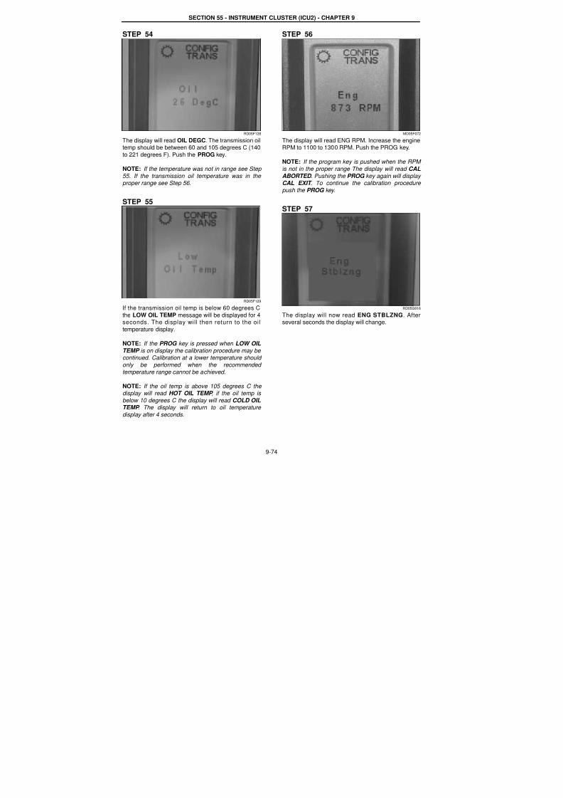
7/23/2019 Case Error Codes
http://slidepdf.com/reader/full/case-error-codes 74/140
SECTION 55 - INSTRUMENT CLUSTER (ICU2) - CHAPTER 9
9-74
STEP 54
RD05F128
The display will read OIL DEGC. The transmission oiltemp should be between 60 and 105 degrees C (140
to 221 degrees F). Push the PROG key.
NOTE: If the temperature was not in range see Step
55. If the transmission oil temperature was in the proper range see Step 56.
STEP 55
RD05F129
If the transmission oil temp is below 60 degrees C
the LOW OIL TEMP message will be displayed for 4seconds. The display will then return to the oil
temperature display.
NOTE: If the PROG key is pressed when LOW OIL
TEMP is on display the calibration procedure may be continued. Calibration at a lower temperature should
only be performed when the recommended
temperature range cannot be achieved.
NOTE: If the oil temp is above 105 degrees C the display will read HOT OIL TEMP , if the oil temp is
below 10 degrees C the display will read COLD OIL
TEMP . The display will return to oil temperature
display after 4 seconds.
STEP 56
MD05F072
The display will read ENG RPM. Increase the engineRPM to 1100 to 1300 RPM. Push the PROG key.
NOTE: If the program key is pushed when the RPM
is not in the proper range The display will read CAL
ABORTED . Pushing the PROG key again will display CAL EXIT . To continue the calibration procedure
push the PROG key.
STEP 57
RD05G016
The display will now read ENG STBLZNG. Afterseveral seconds the display will change.
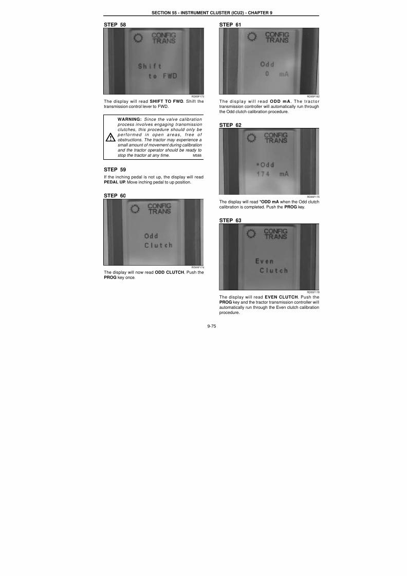
7/23/2019 Case Error Codes
http://slidepdf.com/reader/full/case-error-codes 75/140
SECTION 55 - INSTRUMENT CLUSTER (ICU2) - CHAPTER 9
9-75
STEP 58
RD05F173
The display will read SHIFT TO FWD. Shift thetransmission control lever to FWD.
STEP 59
If the inching pedal is not up, the display will read
PEDAL UP. Move inching pedal to up position.
STEP 60
RD05F174
The display will now read ODD CLUTCH. Push thePROG key once.
STEP 61
RD05F18
The d isp lay wi l l read ODD mA . The t ractotransmission controller will automatically run through
the Odd clutch calibration procedure.
STEP 62
RD05F17
The display will read *ODD mA when the Odd clutch
calibration is completed. Push the PROG key.
STEP 63
RD05F17
The display will read EVEN CLUTCH. Push thePROG key and the tractor transmission controller wil
automatically run through the Even clutch calibration
procedure.
WARNING: Since the valve calibration process involves engaging transmission
clutches, this procedure should only be per fo rmed in open areas , f ree o f
obstructions. The tractor may experience a
small amount of movement during calibration and the tractor operator should be ready to
stop the tractor at any time. M588
!
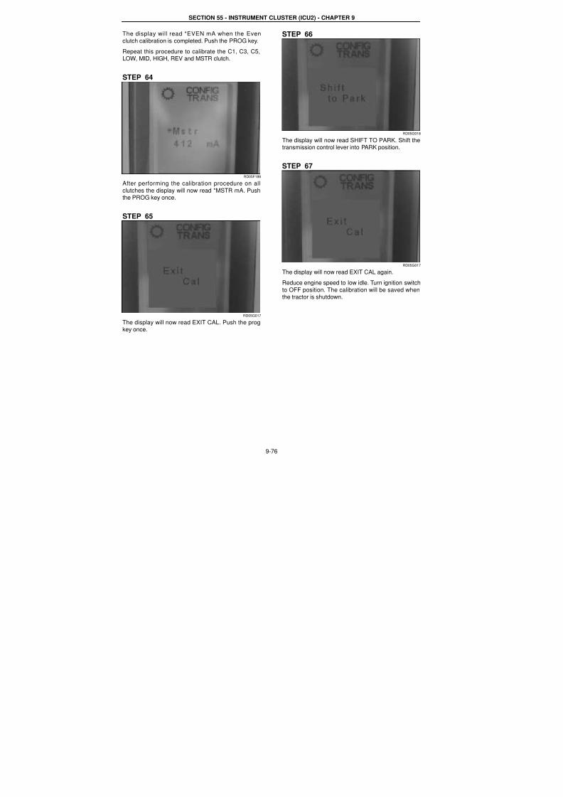
7/23/2019 Case Error Codes
http://slidepdf.com/reader/full/case-error-codes 76/140
SECTION 55 - INSTRUMENT CLUSTER (ICU2) - CHAPTER 9
9-76
The display will read *EVEN mA when the Even
clutch calibration is completed. Push the PROG key.
Repeat this procedure to calibrate the C1, C3, C5,LOW, MID, HIGH, REV and MSTR clutch.
STEP 64
RD05F186
After performing the calibration procedure on all
clutches the display will now read *MSTR mA. Pushthe PROG key once.
STEP 65
RD05G017
The display will now read EXIT CAL. Push the progkey once.
STEP 66
RD05G018
The display will now read SHIFT TO PARK. Shift thetransmission control lever into PARK position.
STEP 67
RD05G017
The display will now read EXIT CAL again.
Reduce engine speed to low idle. Turn ignition switch
to OFF position. The calibration will be saved whenthe tractor is shutdown.
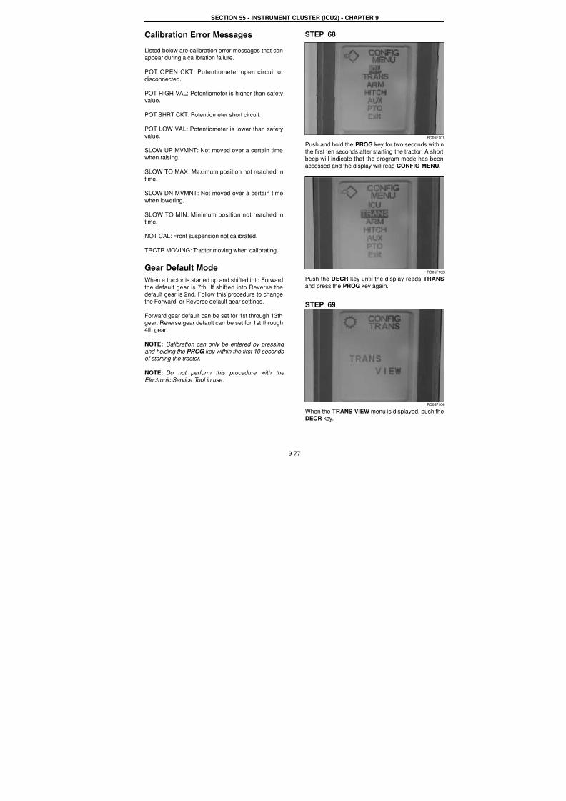
7/23/2019 Case Error Codes
http://slidepdf.com/reader/full/case-error-codes 77/140
SECTION 55 - INSTRUMENT CLUSTER (ICU2) - CHAPTER 9
9-77
Calibration Error Messages
Listed below are calibration error messages that can
appear during a calibration failure.
POT OPEN CKT: Potentiometer open circuit or
disconnected.
POT HIGH VAL: Potentiometer is higher than safetyvalue.
POT SHRT CKT: Potentiometer short circuit.
POT LOW VAL: Potentiometer is lower than safetyvalue.
SLOW UP MVMNT: Not moved over a certain time
when raising.
SLOW TO MAX: Maximum position not reached in
time.
SLOW DN MVMNT: Not moved over a certain time
when lowering.
SLOW TO MIN: Minimum position not reached intime.
NOT CAL: Front suspension not calibrated.
TRCTR MOVING: Tractor moving when calibrating.
Gear Default ModeWhen a tractor is started up and shifted into Forward
the default gear is 7th. If shifted into Reverse thedefault gear is 2nd. Follow this procedure to change
the Forward, or Reverse default gear settings.
Forward gear default can be set for 1st through 13thgear. Reverse gear default can be set for 1st through
4th gear.
NOTE: Calibration can only be entered by pressing
and holding the PROG key within the first 10 seconds of starting the tractor.
NOTE: Do not perform this procedure with the
Electronic Service Tool in use.
STEP 68
RD05F10
Push and hold the PROG key for two seconds within
the first ten seconds after starting the tractor. A shorbeep will indicate that the program mode has been
accessed and the display will read CONFIG MENU.
RD05F10
Push the DECR key until the display reads TRANSand press the PROG key again.
STEP 69
RD05F10
When the TRANS VIEW menu is displayed, push theDECR key.
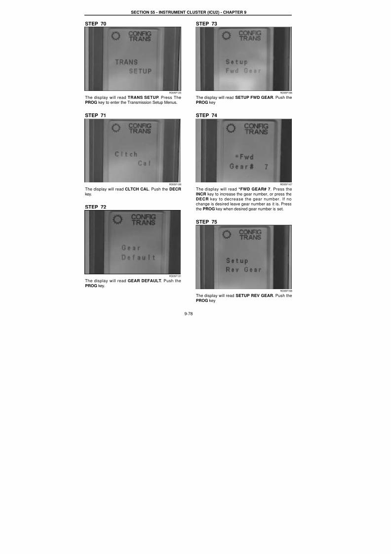
7/23/2019 Case Error Codes
http://slidepdf.com/reader/full/case-error-codes 78/140
SECTION 55 - INSTRUMENT CLUSTER (ICU2) - CHAPTER 9
9-78
STEP 70
RD05F125
The display will read TRANS SETUP. Press ThePROG key to enter the Transmission Setup Menus.
STEP 71
RD05F126
The display will read CLTCH CAL. Push the DECRkey.
STEP 72
RD05F131
The display will read GEAR DEFAULT. Push the
PROG key.
STEP 73
RD05F166
The display will read SETUP FWD GEAR. Push thePROG key
STEP 74
RD05F167
The display will read *FWD GEAR# 7. Press theINCR key to increase the gear number, or press the
DECR key to decrease the gear number. If nochange is desired leave gear number as it is. Press
the PROG key when desired gear number is set.
STEP 75
RD05F168
The display will read SETUP REV GEAR. Push thePROG key

7/23/2019 Case Error Codes
http://slidepdf.com/reader/full/case-error-codes 79/140
SECTION 55 - INSTRUMENT CLUSTER (ICU2) - CHAPTER 9
9-79
STEP 76
RD05F169
The display will read *REV GEAR# 2. Press theINCR key to increase the gear number, or press the
DECR key to decrease the gear number. If nochange is desired leave gear number as i t is. Press
the PROG key when desired gear number is set.
STEP 77
RD05F17
The display will read EXIT SET GEAR. Press thePROG key to exit this menu.
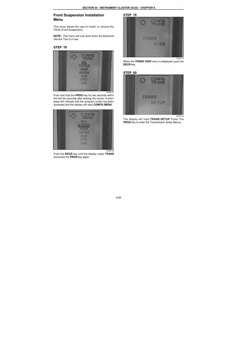
7/23/2019 Case Error Codes
http://slidepdf.com/reader/full/case-error-codes 80/140
SECTION 55 - INSTRUMENT CLUSTER (ICU2) - CHAPTER 9
9-80
Front Suspension Installation
Menu
This menu allows the user to install, or remove the
FSUS (Front Suspension).
NOTE: This menu will only work when the Electronic
Service Tool is in use.
STEP 78
RD05F101
Push and hold the PROG key for two seconds within
the first ten seconds after starting the tractor. A shortbeep will indicate that the program mode has been
accessed and the display will read CONFIG MENU.
RD05F103
Push the DECR key until the display reads TRANS
and press the PROG key again.
STEP 79
RD05F104
When the TRANS VIEW menu is displayed, push theDECR key.
STEP 80
RD05F125
The display will read TRANS SETUP. Press ThePROG key to enter the Transmission Setup Menus.
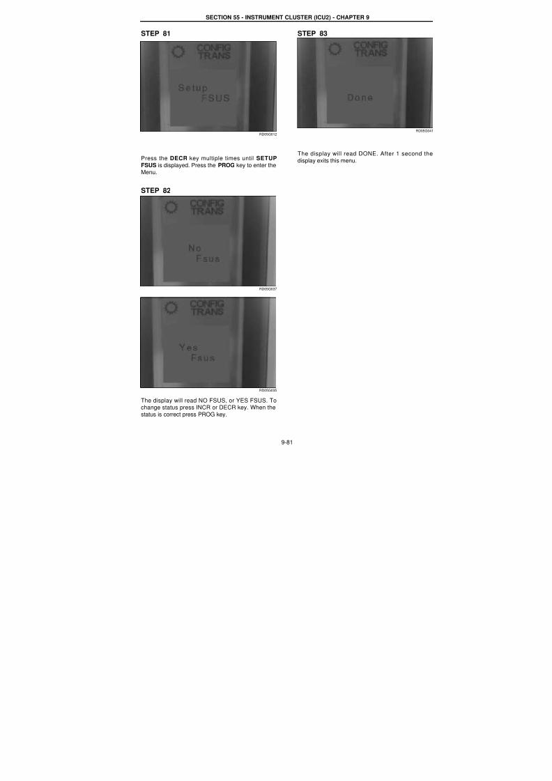
7/23/2019 Case Error Codes
http://slidepdf.com/reader/full/case-error-codes 81/140
SECTION 55 - INSTRUMENT CLUSTER (ICU2) - CHAPTER 9
9-81
STEP 81
RD05G012
Press the DECR key multiple times until SETUP
FSUS is displayed. Press the PROG key to enter the
Menu.
STEP 82
RD05G037
RD05G035
The display will read NO FSUS, or YES FSUS. Tochange status press INCR or DECR key. When the
status is correct press PROG key.
STEP 83
RD05G04
The display will read DONE. After 1 second the
display exits this menu.

7/23/2019 Case Error Codes
http://slidepdf.com/reader/full/case-error-codes 82/140
SECTION 55 - INSTRUMENT CLUSTER (ICU2) - CHAPTER 9
9-82
Front Suspension Menus
The following menus are available for the FrontSuspension.
1. FSUS CAL - This menu allows the user to
Calibrate the Front Suspended axle.
2. FSUS DEMO - This menu can only be accessed
when the Electronic Service Tool (EST) is in use
on the tractor. It allows the user to switch theFront Suspended Axle ON or OFF especially at
speeds greater than 12 KMH.
3. FSUS MANUAL - This menu allows the operatorto manually operate the Front Suspension. The
axle may be raised or lowered when the tractor isstationary.
4. EXIT FSUS- This menu entry will exit the Front
Suspension Menus.
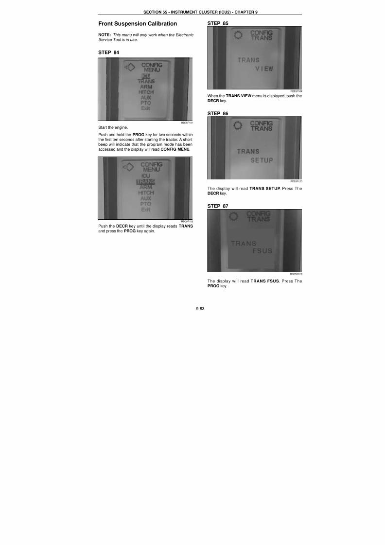
7/23/2019 Case Error Codes
http://slidepdf.com/reader/full/case-error-codes 83/140
SECTION 55 - INSTRUMENT CLUSTER (ICU2) - CHAPTER 9
9-83
Front Suspension Calibration
NOTE: This menu will only work when the Electronic Service Tool is in use.
STEP 84
RD05F101
Start the engine.
Push and hold the PROG key for two seconds within
the first ten seconds after starting the tractor. A shortbeep will indicate that the program mode has been
accessed and the display will read CONFIG MENU.
RD05F103
Push the DECR key until the display reads TRANS
and press the PROG key again.
STEP 85
RD05F10
When the TRANS VIEW menu is displayed, push theDECR key.
STEP 86
RD05F12
The display will read TRANS SETUP. Press TheDECR key.
STEP 87
RD05G01
The display will read TRANS FSUS. Press ThePROG key.
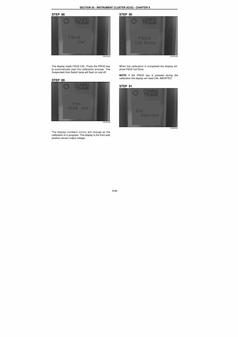
7/23/2019 Case Error Codes
http://slidepdf.com/reader/full/case-error-codes 84/140
SECTION 55 - INSTRUMENT CLUSTER (ICU2) - CHAPTER 9
9-84
STEP 88
RD05G042
The display reads FSUS CAL. Press the PROG key
to automatically start the calibration process. TheSuspended Axle Switch lamp will flash on and off.
STEP 89
RD05G030
The display numbers (nnnn) will change as thecalibration is in progress. This display is the front axle
position sensor output voltage.
STEP 90
RD05G026
When the calibration is completed the display will
show FSUS Cal Done.
NOTE: If the PROG key is pressed during the calibration the display will read CAL ABORTED.
STEP 91
RD05G043

7/23/2019 Case Error Codes
http://slidepdf.com/reader/full/case-error-codes 85/140
SECTION 55 - INSTRUMENT CLUSTER (ICU2) - CHAPTER 9
9-85
RD05G044
If the calibration process fails the display will read
CAL FAILED. The Suspended Axle Switch lamp willturn off. If the CAL FAILED message appears press
the PROG key to access the Error Message Display.
STEP 92
RD05G047
Error Message Display Example.
Possible Error Messages
tttt bbbbbbbb
POT OPEN CKT
POT HIGH VAL
POT SHRT CKT
POT LOW VAL
POT LOW RNG
SLOW UP MVMNT
SLOW TO MAX
SLOW DN MVMNT
SLOW TO MIN
NOT CAL
WHEEL MOVED
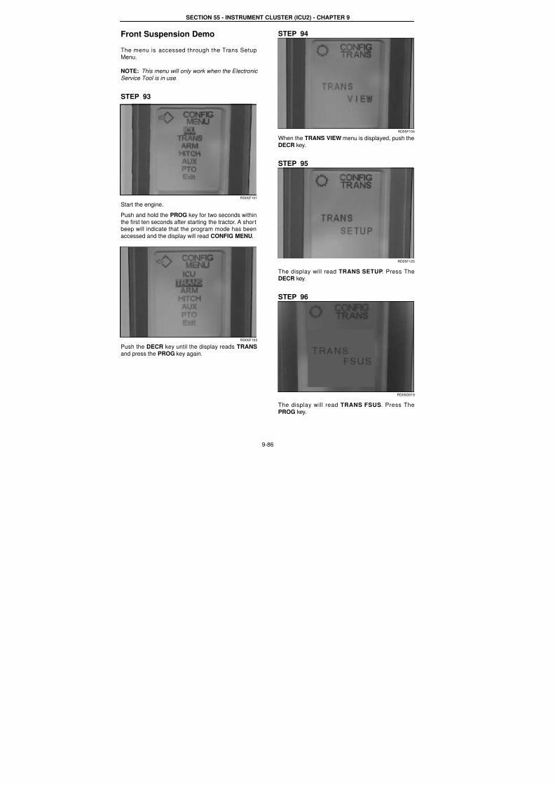
7/23/2019 Case Error Codes
http://slidepdf.com/reader/full/case-error-codes 86/140
SECTION 55 - INSTRUMENT CLUSTER (ICU2) - CHAPTER 9
9-86
Front Suspension Demo
The menu is accessed through the Trans SetupMenu.
NOTE: This menu will only work when the Electronic
Service Tool is in use.
STEP 93
RD05F101
Start the engine.
Push and hold the PROG key for two seconds within
the first ten seconds after starting the tractor. A shortbeep will indicate that the program mode has been
accessed and the display will read CONFIG MENU.
RD05F103
Push the DECR key until the display reads TRANS
and press the PROG key again.
STEP 94
RD05F104
When the TRANS VIEW menu is displayed, push theDECR key.
STEP 95
RD05F125
The display will read TRANS SETUP. Press TheDECR key.
STEP 96
RD05G019
The display will read TRANS FSUS. Press ThePROG key.
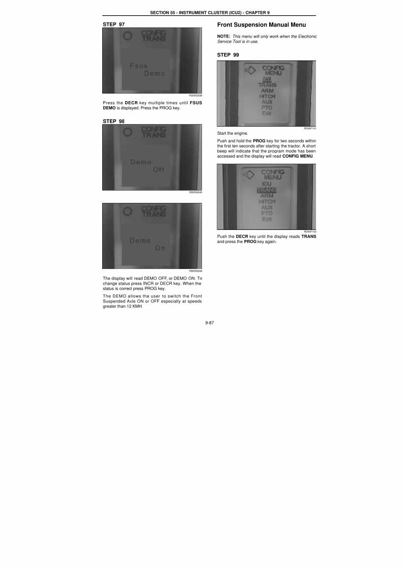
7/23/2019 Case Error Codes
http://slidepdf.com/reader/full/case-error-codes 87/140
SECTION 55 - INSTRUMENT CLUSTER (ICU2) - CHAPTER 9
9-87
STEP 97
RD05G038
Press the DECR key multiple times until FSUS
DEMO is displayed. Press the PROG key.
STEP 98
RD05G040
RD05G039
The display will read DEMO OFF, or DEMO ON. To
change status press INCR or DECR key. When thestatus is correct press PROG key.
The DEMO allows the user to switch the Front
Suspended Axle ON or OFF especially at speedsgreater than 12 KMH.
Front Suspension Manual Menu
NOTE: This menu will only work when the ElectronicService Tool is in use.
STEP 99
RD05F10
Start the engine.
Push and hold the PROG key for two seconds within
the first ten seconds after starting the tractor. A shorbeep will indicate that the program mode has been
accessed and the display will read CONFIG MENU.
RD05F10
Push the DECR key until the display reads TRANS
and press the PROG key again.
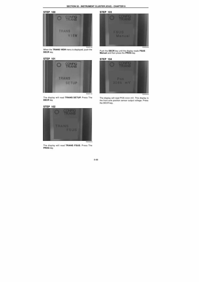
7/23/2019 Case Error Codes
http://slidepdf.com/reader/full/case-error-codes 88/140
SECTION 55 - INSTRUMENT CLUSTER (ICU2) - CHAPTER 9
9-88
STEP 100
RD05F104
When the TRANS VIEW menu is displayed, push theDECR key.
STEP 101
RD05F125
The display will read TRANS SETUP. Press TheDECR key.
STEP 102
RD05G019
The display will read TRANS FSUS. Press ThePROG key.
STEP 103
RD05G028
Push the DECR key until the display reads FSUSManual and then press the PROG key.
STEP 104
RD05G030
The display will read POS nnnn mV. This display isthe front axle position sensor output voltage. Press
the DECR key.
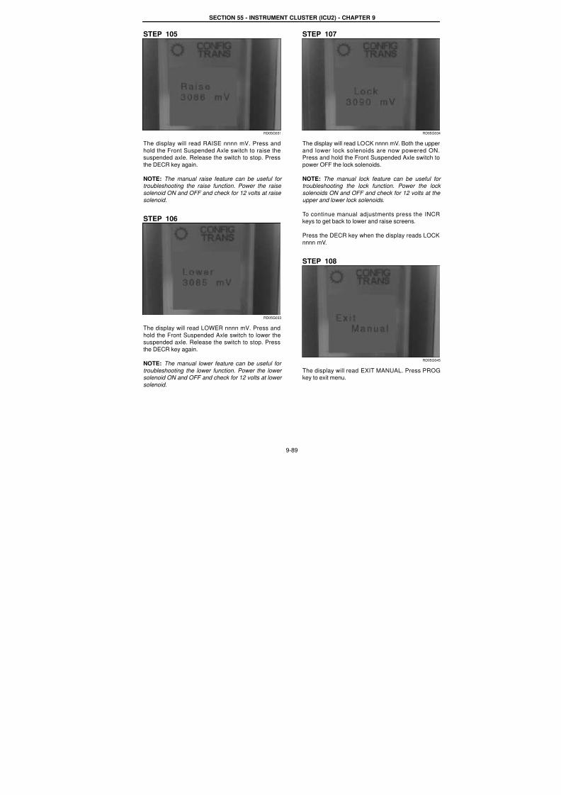
7/23/2019 Case Error Codes
http://slidepdf.com/reader/full/case-error-codes 89/140
SECTION 55 - INSTRUMENT CLUSTER (ICU2) - CHAPTER 9
9-89
STEP 105
RD05G031
The display will read RAISE nnnn mV. Press and
hold the Front Suspended Axle switch to raise thesuspended axle. Release the switch to stop. Press
the DECR key again.
NOTE: The manual raise feature can be useful for troubleshooting the raise function. Power the raise
solenoid ON and OFF and check for 12 volts at raise
solenoid.
STEP 106
RD05G033
The display will read LOWER nnnn mV. Press and
hold the Front Suspended Axle switch to lower thesuspended axle. Release the switch to stop. Press
the DECR key again.
NOTE: The manual lower feature can be useful for
troubleshooting the lower function. Power the lower solenoid ON and OFF and check for 12 volts at lower
solenoid.
STEP 107
RD05G03
The display will read LOCK nnnn mV. Both the uppe
and lower lock solenoids are now powered ONPress and hold the Front Suspended Axle switch to
power OFF the lock solenoids.
NOTE: The manual lock feature can be useful fotroubleshooting the lock function. Power the lock
solenoids ON and OFF and check for 12 volts at the
upper and lower lock solenoids.
To continue manual adjustments press the INCRkeys to get back to lower and raise screens.
Press the DECR key when the display reads LOCK
nnnn mV.
STEP 108
RD05G04
The display will read EXIT MANUAL. Press PROGkey to exit menu.
7/23/2019 Case Error Codes
http://slidepdf.com/reader/full/case-error-codes 90/140
9-90
Template Name: OML_2_col Rac 0-00000Template Date: 2001_03_06
SECTION 55 - INSTRUMENT CLUSTER (ICU2) - CHAPTER 9
TRANSMISSION CONTROLLER FAULT CODES
TRANS 60 FNRP pod in illogical state (in no position)
Cause:
If FNRP pot indicates not in neutral, not in forward, and not in reverse for 2.5 seconds, the transmission controller
will record this fault code. Possible failure modes:
1. The operator may be holding the lever up for too long.
2. The transmission control (FNRP) pot failure
3. Wiring harness problem from the transmission control (FNRP) pot to the transmission controller.
Solution:
The transmission control (FNRP) pod is directly wired to the transmission controller. The transmission controllermonitors the shuttle shifting and displays the shuttle position on the instrumentation cluster.
1. Make sure the operator is not holding the lever up for too long.
2. Troubleshooting by viewing the shuttle position display.In some cases, problems can be detected by viewing the display while shifting the transmission control (FNRP
lever.Turn Key 'ON' and watch the shuttle position display.
If Forward icon does not lit up on display when in Forward, either the Forward switch failed open or its wiringshorted to ground.
If Reverse icon does not lit up on display when in Reverse, either the Reverse switch failed open or its wiring
shorted to ground.If Neutral icon does not lit up steady when in Neutral or Park, either the Neutral switch failed closed or its wiring
shorted to power.
3. Troubleshooting by checking FNRP switch function.Disconnect the cover panel under the Armrest (steering column for MU8). Locate connector C051. Measure
continuities on the transmission control (FNRP) pot side.
Measure between Pin 6 (Forward) and Pin 8 (5 Vref), there should be about 500 - 600 Ohms when in Forwardposition and about 2500 - 3000 Ohms when in other positions. If not, the Forward switch failed.
Measure between Pin 5 (Reverse) and Pin 8, there should be about 500 - 600 Ohms when in Reverse position andabout 2500 - 3000 Ohms when in other positions. If not, the Reverse switch fails open.
Measure between Pin 7 (not Neutral) and Pin 3, there should be no continuity in Park or Neutral position and thereshould be continuity in Forward or Reverse positions. If not, the Neutral switch failed.
NOTE: Neutral switch off indicates tractor is in Neutral. Neutral switch on indicates tractor is not in Park.
If any above switch failure is detected, replace the transmission control (FNRP) pot.
If no switch failure is detected, go to next step.
4. Check the wiring from connector C051 to the transmission controller.Check the wiring from connector C051 to connector C351 on the transmission controller.
Follow the wiring schematics. Conduct continuity checking (in a similar way to the way specified in step 2) betweenpins at each connectors.
NOTE: Pay attention to bent pin, loose pin, wire damage, and any possible shortage between pins and wires.

7/23/2019 Case Error Codes
http://slidepdf.com/reader/full/case-error-codes 91/140
SECTION 55 - INSTRUMENT CLUSTER (ICU2) - CHAPTER 9
9-91
TRANS 76Transmission over speed
Cause:
The transmission controller is hard wired to the wheel speed sensor. This fault code is recorded each time the
transmission is oversped.
Possible failure modes:
1. The transmission was oversped.
Solution:
1. Take precautions to avoid over-speeding the transmission. Select lower gear when traveling down inclinesespecially when pulling heavy loads.
7/23/2019 Case Error Codes
http://slidepdf.com/reader/full/case-error-codes 92/140
SECTION 55 - INSTRUMENT CLUSTER (ICU2) - CHAPTER 9
9-92
TRANS 136Communication lost with the instrumentation controller
Cause:
Communication lost between transmission controller and instrumentation controller.
Possible Failure modes:
1. Bad Can Bus connection between the transmission controller and instrumentation controller.
2. Controller failure.
Solution:
Make sure both the transmission controller and instrumentation controller are functioning OK.
Check the Data Bus connections.
1. Check the function of the transmission controller:Make sure there is no other fault code or symptom indicating transmission controller malfunctioning.
2. Check the function of the Instrument controller:
A. If there is no display and no back light on the tractor instrumentation, it is more likely that there is no power
to controller. Check power supply, its fuse, and the ground to the controller. Make sure the connector
(CN2) to the Instrument controller is plugged in.
B. If there is display on the tractor instrumentation but the display is erratic, such as totally strange symbols,
and other controllers claim communication lost with the Instrument controller, it is more like the Instrument
controller failed. Replace the controller.
C. If nothing wrong can be found with the Instrument controller, go to step 3.
3. Check the power supply to the Data Bus.
The power supply to the Data Bus is from the switched power through Fuse #41.A. Make sure Fuse #41 is not burned out.
B. Turn the tractor Key 'ON'. Check the power supply at Fuse #41. There should be 12 volts.
If not, check the power supply from the switched power.
4. Check the integrity of Data Bus at the Passive Terminators.The following checks are basically looking into one end of the bus and check the terminator at the other end.
A. Check from the Passive Terminator at the Rear of the Tractor
Disconnect the terminator at connector C175.With the key on, measure the voltage on the wires connected to C175.
At pin 1, the red wire, it should read 12 volts battery voltage.
At pin 2, the yellow wire, it should read 2.5 to 1 volts (2.5 V nominally).At pin 3, the black wire, there should be continuity from pin 3 to the clean ground.
At pin 4, the green wire, it should read 2.5 to 1 volts (2.5 V nominally).If the above checks are ok, it means that the front terminator and data bus wiring is ok.
If not, go to next.
B. Check from the Passive Terminator at the Front of the TractorReconnect the rear terminator and disconnect the front terminator at connector C205.
With the key on, measure the voltage on the wires connected to C205.At pin 1, the red wire, it should read 12 volts battery voltage.
At pin 2, the yellow wire, it should read 2.5 to 1 volts (2.5 V nominally).At pin 3, the black wire, there should be continuity from pin 3 to the clean ground.

7/23/2019 Case Error Codes
http://slidepdf.com/reader/full/case-error-codes 93/140
SECTION 55 - INSTRUMENT CLUSTER (ICU2) - CHAPTER 9
9-93
At pin 4, the green wire, it should read 2.5 to 1 volts (2.5 V nominally).
If the above checks are ok, it means that the rear terminator and data bus wiring is ok.If not, check for bad connection and damaged wire along the Data Bus.
NOTE: When there is a bad connection along the Data Bus wiring, the fault code will be accompanied by multiple
fault codes such as TRANS 135, PTO 54120, INST 12011, AUX 12011, INST 12031, and PTO 54140.
NOTE: Pay good attention to loose connectors, bent pins in the connector, and wire damage.
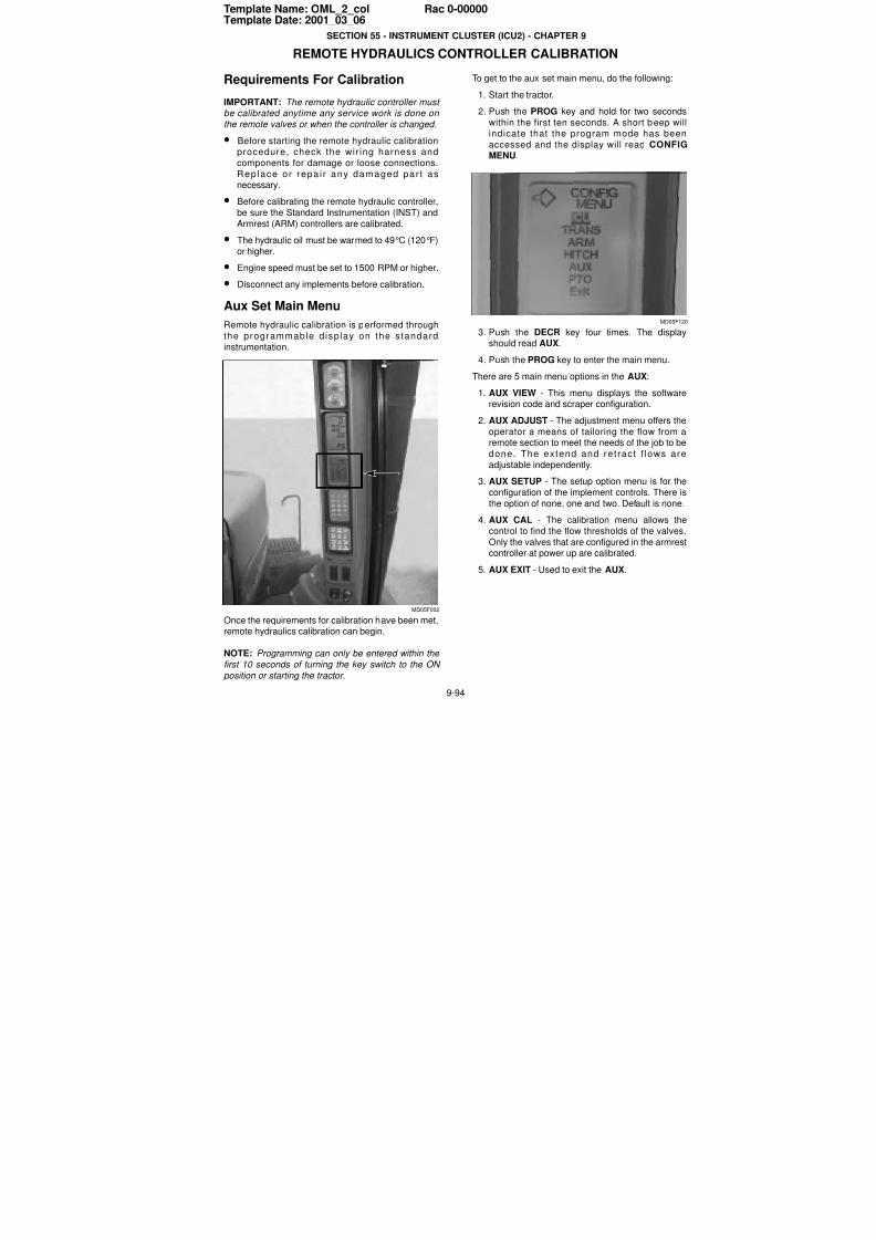
7/23/2019 Case Error Codes
http://slidepdf.com/reader/full/case-error-codes 94/140
9-94
Template Name: OML_2_col Rac 0-00000Template Date: 2001_03_06
SECTION 55 - INSTRUMENT CLUSTER (ICU2) - CHAPTER 9
REMOTE HYDRAULICS CONTROLLER CALIBRATION
Requirements For Calibration
IMPORTANT: The remote hydraulic controller must be calibrated anytime any service work is done on
the remote valves or when the controller is changed.
• Before starting the remote hydraulic calibrationprocedure, check the wir ing harness and
components for damage or loose connections.
Rep lace or repa i r any damaged par t asnecessary.
• Before calibrating the remote hydraulic controller,
be sure the Standard Instrumentation (INST) and
Armrest (ARM) controllers are calibrated.
• The hydraulic oil must be warmed to 49°C (120°F)or higher.
• Engine speed must be set to 1500 RPM or higher.
• Disconnect any implements before calibration.
Aux Set Main Menu
Remote hydraulic calibration is performed through
the programmable d isp lay on the s tandard
instrumentation.
MD05F002
Once the requirements for calibration have been met,remote hydraulics calibration can begin.
NOTE: Programming can only be entered within the
first 10 seconds of turning the key switch to the ON
position or starting the tractor.
To get to the aux set main menu, do the following:
1. Start the tractor.
2. Push the PROG key and hold for two seconds
within the first ten seconds. A short beep wilindicate that the program mode has been
accessed and the display will read CONFIGMENU.
MD05F12
3. Push the DECR key four times. The displayshould read AUX.
4. Push the PROG key to enter the main menu.
There are 5 main menu options in the AUX:
1. AUX VIEW - This menu displays the softwarerevision code and scraper configuration.
2. AUX ADJUST - The adjustment menu offers theoperator a means of tailoring the flow from aremote section to meet the needs of the job to be
done. The extend and ret ract f lows are
adjustable independently.
3. AUX SETUP - The setup option menu is for the
configuration of the implement controls. There is
the option of none, one and two. Default is none.
4. AUX CAL - The calibration menu allows the
control to find the flow thresholds of the valves
Only the valves that are configured in the armrescontroller at power up are calibrated.
5. AUX EXIT - Used to exit the AUX.
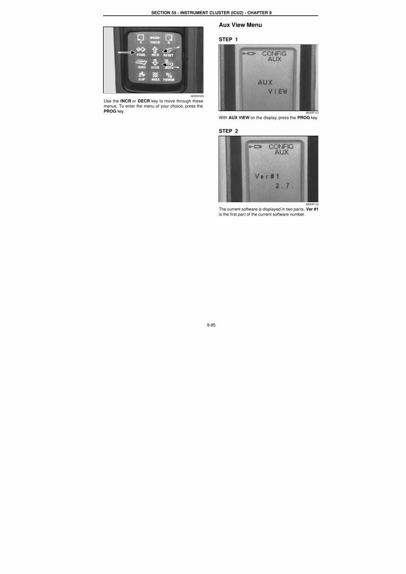
7/23/2019 Case Error Codes
http://slidepdf.com/reader/full/case-error-codes 95/140
SECTION 55 - INSTRUMENT CLUSTER (ICU2) - CHAPTER 9
9-95
MD05F003
Use the INCR or DECR key to move through thesemenus. To enter the menu of your choice, press the
PROG key.
Aux View Menu
STEP 1
MD05F12
With AUX VIEW on the display, press the PROG key
STEP 2
MD05F12
The current software is displayed in two parts. Ver #1
is the first part of the current software number.
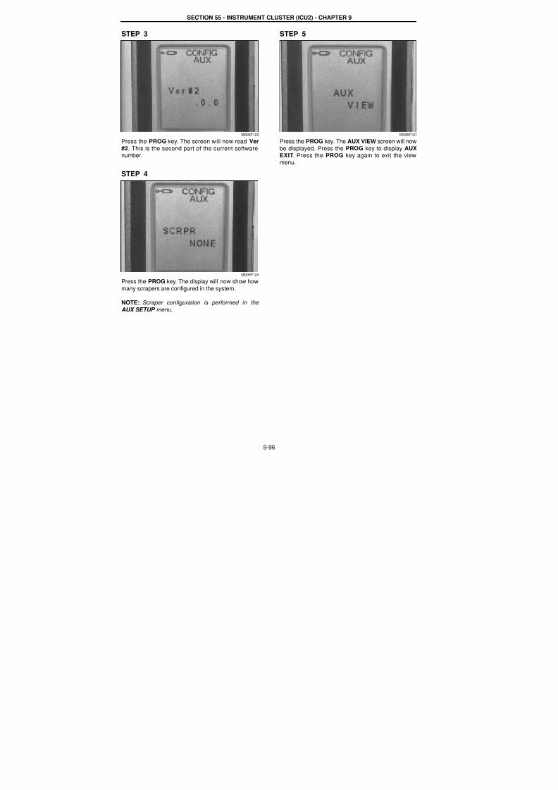
7/23/2019 Case Error Codes
http://slidepdf.com/reader/full/case-error-codes 96/140
SECTION 55 - INSTRUMENT CLUSTER (ICU2) - CHAPTER 9
9-96
STEP 3
MD05F123
Press the PROG key. The screen will now read Ver#2. This is the second part of the current softwarenumber.
STEP 4
MD05F124
Press the PROG key. The display will now show how
many scrapers are configured in the system.
NOTE: Scraper configuration is performed in the
AUX SETUP menu.
STEP 5
MD05F121
Press the PROG key. The AUX VIEW screen will now
be displayed. Press the PROG key to display AUX
EXIT. Press the PROG key again to exit the view
menu.
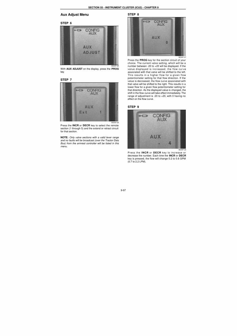
7/23/2019 Case Error Codes
http://slidepdf.com/reader/full/case-error-codes 97/140
SECTION 55 - INSTRUMENT CLUSTER (ICU2) - CHAPTER 9
9-97
Aux Adjust Menu
STEP 6
MD05F125
With AUX ADJUST on the display, press the PROGkey.
STEP 7
MD05F126
Press the INCR or DECR key to select the remotesection (1 through 5) and the extend or retract circuit
for that section.
NOTE: Only valve sections with a valid lever range and no faults will be broadcast (over the Tractor Data
Bus) from the armrest controller will be listed in this
menu.
STEP 8
MD05F12
Press the PROG key for the section circuit of you
choice. The current valve setting, which will be anumber between -20 to +20 will be displayed. If the
value displayed is increased, the f low cur veassociated with that valve will be shifted to the left
This results in a higher f low for a given f lowpotentiometer setting for that flow direction. If the
value is decreased, the flow curve associated with
that valve will be shifted to the right. This results in alower flow for a given flow potentiometer setting for
that direction. As the displayed value is changed, theshift in the flow curve will take effect immediately. The
range of adjustment is -20 to +20, with 0 having noeffect on the flow curve.
STEP 9
MD05F12
Press the INCR or DECR key to increase ordecrease the number. Each time the INCR or DECR
key is pressed, the flow will change 0.2 to 0.6 GPM(0.7 to 2.2 LPM).
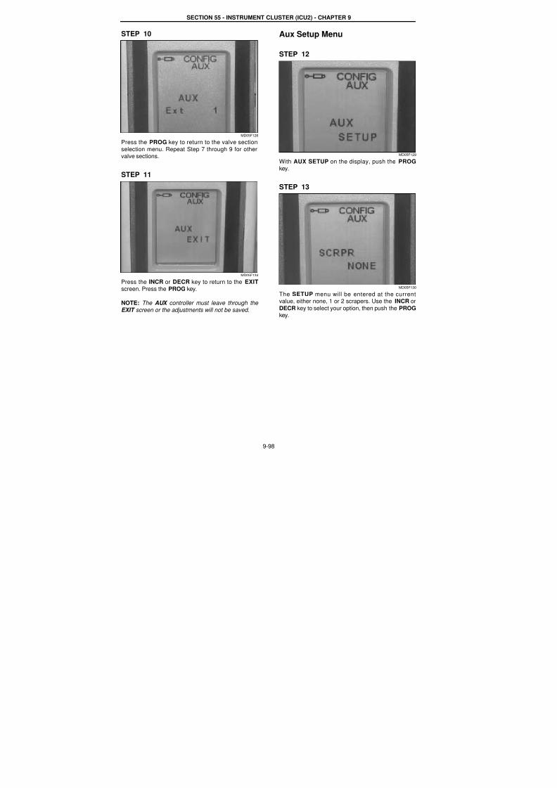
7/23/2019 Case Error Codes
http://slidepdf.com/reader/full/case-error-codes 98/140
SECTION 55 - INSTRUMENT CLUSTER (ICU2) - CHAPTER 9
9-98
STEP 10
MD05F126
Press the PROG key to return to the valve section
selection menu. Repeat Step 7 through 9 for othervalve sections.
STEP 11
MD05F134
Press the INCR or DECR key to return to the EXIT
screen. Press the PROG key.
NOTE: The AUX controller must leave through the
EXIT screen or the adjustments will not be saved.
Aux Setup Menu
STEP 12
MD05F129
With AUX SETUP on the display, push the PROGkey.
STEP 13
MD05F130
The SETUP menu will be entered at the currentvalue, either none, 1 or 2 scrapers. Use the INCR or
DECR key to select your option, then push the PROGkey.
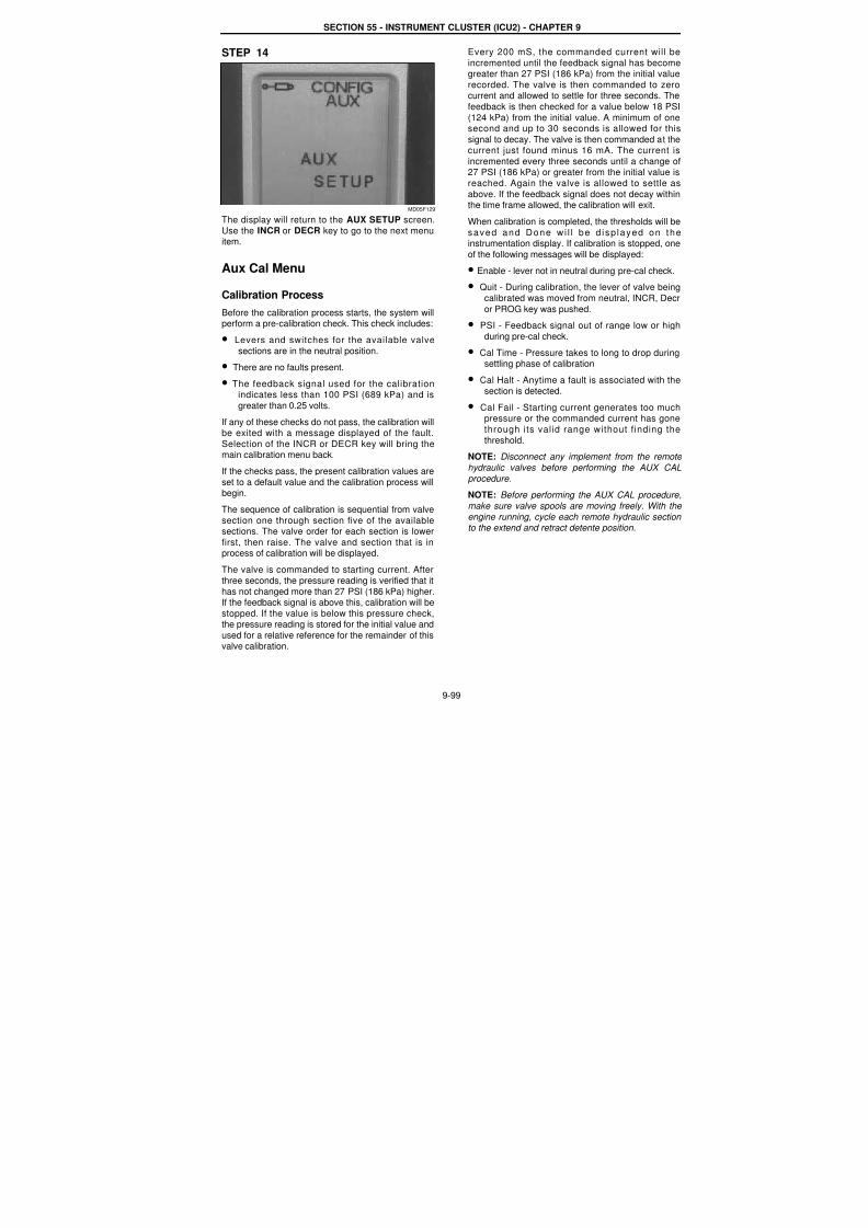
7/23/2019 Case Error Codes
http://slidepdf.com/reader/full/case-error-codes 99/140
SECTION 55 - INSTRUMENT CLUSTER (ICU2) - CHAPTER 9
9-99
STEP 14
MD05F129
The display will return to the AUX SETUP screen.
Use the INCR or DECR key to go to the next menuitem.
Aux Cal Menu
Calibration Process
Before the calibration process starts, the system willperform a pre-calibration check. This check includes:
• Levers and switches for the available valve
sections are in the neutral position.
• There are no faults present.
• The feedback signal used for the calibrationindicates less than 100 PSI (689 kPa) and is
greater than 0.25 volts.
If any of these checks do not pass, the calibration willbe exited with a message displayed of the fault.
Selection of the INCR or DECR key will bring themain calibration menu back.
If the checks pass, the present calibration values are
set to a default value and the calibration process willbegin.
The sequence of calibration is sequential from valve
section one through section five of the availablesections. The valve order for each section is lower
first, then raise. The valve and section that is in
process of calibration will be displayed.The valve is commanded to starting current. After
three seconds, the pressure reading is verified that it
has not changed more than 27 PSI (186 kPa) higher.If the feedback signal is above this, calibration will be
stopped. If the value is below this pressure check,the pressure reading is stored for the initial value and
used for a relative reference for the remainder of thisvalve calibration.
Every 200 mS, the commanded current will be
incremented until the feedback signal has becomegreater than 27 PSI (186 kPa) from the initial value
recorded. The valve is then commanded to zerocurrent and allowed to settle for three seconds. The
feedback is then checked for a value below 18 PS
(124 kPa) from the initial value. A minimum of onesecond and up to 30 seconds is allowed for this
signal to decay. The valve is then commanded at thecurrent just found minus 16 mA. The current is
incremented every three seconds until a change o27 PSI (186 kPa) or greater from the initial value is
reached. Again the valve is allowed to settle as
above. If the feedback signal does not decay withinthe time frame allowed, the calibration will exit.
When calibration is completed, the thresholds will be
saved and Done wi l l be d isp layed on theinstrumentation display. If calibration is stopped, one
of the following messages will be displayed:
• Enable - lever not in neutral during pre-cal check.
• Quit - During calibration, the lever of valve being
calibrated was moved from neutral, INCR, Decr
or PROG key was pushed.
• PSI - Feedback signal out of range low or high
during pre-cal check.
• Cal Time - Pressure takes to long to drop duringsettling phase of calibration
• Cal Halt - Anytime a fault is associated with the
section is detected.
• Cal Fail - Starting current generates too much
pressure or the commanded current has gonethrough its valid range without f inding the
threshold.
NOTE: Disconnect any implement from the remote
hydraulic valves before performing the AUX CAL
procedure.
NOTE: Before performing the AUX CAL procedure
make sure valve spools are moving freely. With the
engine running, cycle each remote hydraulic sectionto the extend and retract detente position.
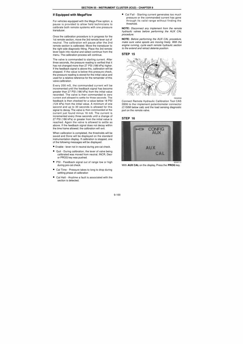
7/23/2019 Case Error Codes
http://slidepdf.com/reader/full/case-error-codes 100/140
SECTION 55 - INSTRUMENT CLUSTER (ICU2) - CHAPTER 9
9-100
If Equipped with MegaFlow
For vehicles equipped with the Mega-Flow option, a
pause is provided to allow field technicians to
calibrate both remote systems with one pressuretransducer.
Once the calibration procedure is in progress for the
1st remote section, move the 3rd remote lever out ofneutral. The calibration will pause after the 2nd
remote section is calibrated. Move the transducer to
the right side diagnostic fitting. Place the 3rd remotelever back into neutral and select continue from the
menu. The calibration process will continue.
The valve is commanded to starting current. Afterthree seconds, the pressure reading is verified that it
has not changed more than 27 PSI (186 kPa) higher.If the feedback signal is above this, calibration will be
stopped. If the value is below this pressure check,the pressure reading is stored for the initial value and
used for a relative reference for the remainder of thisvalve calibration.
Every 200 mS, the commanded current will be
incremented until the feedback signal has become
greater than 27 PSI (186 kPa) from the initial valuerecorded. The valve is then commanded to zero
current and allowed to settle for three seconds. Thefeedback is then checked for a value below 18 PSI
(124 kPa) from the initial value. A minimum of onesecond and up to 30 seconds is allowed for this
signal to decay. The valve is then commanded at the
current just found minus 16 mA. The current is
incremented every three seconds until a change of27 PSI (186 kPa) or greater from the initial value isreached. Again the valve is allowed to settle as
above. If the feedback signal does not decay within
the time frame allowed, the calibration will exit.
When calibration is completed, the thresholds will be
saved and Done will be displayed on the standard
instrumentation display. If calibration is stopped, oneof the following messages will be displayed:
• Enable - lever not in neutral during pre-cal check.
• Quit - During calibration, the lever of valve being
calibrated was moved from neutral, INCR, Decror PROG key was pushed.
• PSI - Feedback signal out of range low or highduring pre-cal check.
• Cal Time - Pressure takes to long to drop during
settling phase of calibration
• Cal Halt - Anytime a fault is associated with thesection is detected.
• Cal Fail - Starting current generates too much
pressure or the commanded current has gonethrough its valid range without f inding the
threshold.
NOTE: Disconnect any implement from the remote hydraulic valves before performing the AUX CAL
procedure.
NOTE: Before performing the AUX CAL procedure,make sure valve spools are moving freely. With the
engine running, cycle each remote hydraulic section
to the extend and retract detente position.
STEP 15
RD02E096
Connect Remote Hydraulic Calibration Tool CAS
2806 to the implement potentiometer connector(C150M below cab) and the load sensing diagnostic
port on the remote valve.
STEP 16
MD05F131
With AUX CAL on the display, Press the PROG key.
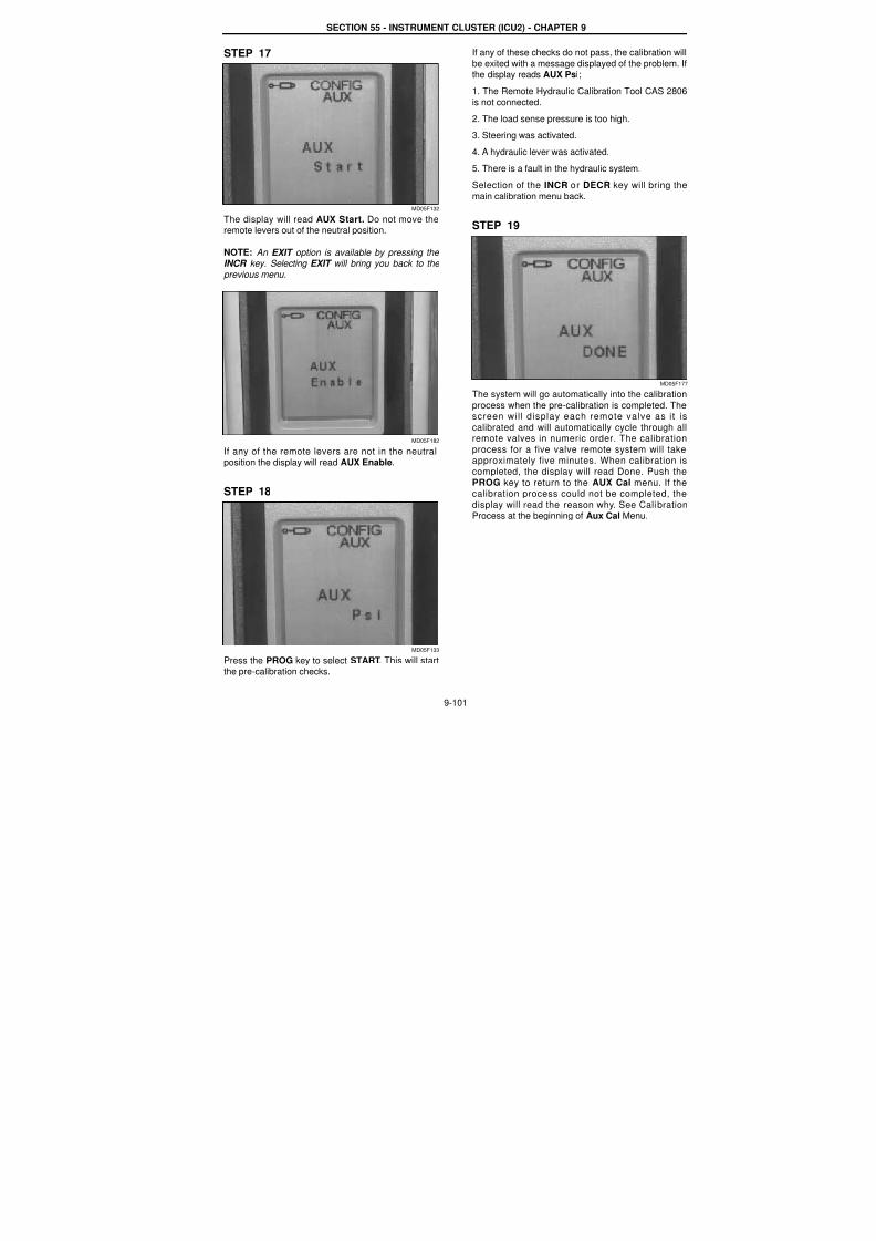
7/23/2019 Case Error Codes
http://slidepdf.com/reader/full/case-error-codes 101/140
SECTION 55 - INSTRUMENT CLUSTER (ICU2) - CHAPTER 9
9-101
STEP 17
MD05F132
The display will read AUX Start. Do not move theremote levers out of the neutral position.
NOTE: An EXIT option is available by pressing the INCR key. Selecting EXIT will bring you back to the
previous menu.
MD05F182
If any of the remote levers are not in the neutralposition the display will read AUX Enable.
STEP 18
MD05F133
Press the PROG key to select START. This will startthe pre-calibration checks.
If any of these checks do not pass, the calibration wil
be exited with a message displayed of the problem. Ithe display reads AUX Psi;
1. The Remote Hydraulic Calibration Tool CAS 2806
is not connected.
2. The load sense pressure is too high.
3. Steering was activated.4. A hydraulic lever was activated.
5. There is a fault in the hydraulic system.
Selection of the INCR or DECR key will bring the
main calibration menu back.
STEP 19
MD05F17
The system will go automatically into the calibration
process when the pre-calibration is completed. The
screen will display each remote valve as it iscalibrated and will automatically cycle through alremote valves in numeric order. The calibration
process for a five valve remote system will takeapproximately five minutes. When calibration is
completed, the display will read Done. Push thePROG key to return to the AUX Cal menu. If thecalibration process could not be completed, the
display will read the reason why. See CalibrationProcess at the beginning of Aux Cal Menu.
7/23/2019 Case Error Codes
http://slidepdf.com/reader/full/case-error-codes 102/140
9-102
Template Name: OML_2_col Rac 0-00000Template Date: 2001_03_06
SECTION 55 - INSTRUMENT CLUSTER (ICU2) - CHAPTER 9
REMOTE (AUX) CONTROLLER FAULT CODES
FAULT CODE AUX 12041Communication Lost With The Instrumentation Controller
Cause:
Communication lost between remote hydraulic controller and the instrumentation controller.
Possible failure modes:1. Bad connection between remote hydraulic controller and the instrumentation controller.
2. Controller failure.
Solution:
Make sure both the armrest controller and the remote hydraulic controller are functioning OK.Check the Data Bus connections.
1. Check the function of the remote hydraulic controller:
a) Make sure connector (C055 Green) is plugged in to the remote hydraulic controller.b) Check the LED light on the remote hydraulic controller.
The LED light for remote hydraulic controller is on the bottom of the controller.LED light on - failed controller, replace the controller.
LED light flashing - controller is OK.LED off - no power to controller, check power supply and its fuse.
2. Check the function of the Instrument controller:
a) If there is no display and no back light on the tractor instrumentation, it is more likely that there is no powerto controller. Check power supply, its fuse, and the ground to the controller. Make sure the connector (CN2) to
the Instrument controller is plugged in.
b) If there is display on the tractor instrumentation but the display is erratic, such as totally strange symbols,and other controllers claim communication lost with the Instrument controller, it is more likely the Instrument
controller failed, replace the controller.c) If the display is normal, go to step 3.
3. Check the power supply to the Data Bus.
The power supply to the Data Bus is from the switched power through Fuse #41.
a) Make sure Fuse #41 is not burned out.b) Turn the tractor Key ‘ON’. Check the power supply at Fuse #41. There should be 12 volts.If not, check the power supply from the switched power.
4. Check the integrity of Data Bus at the passive terminators.
The following checks are basically looking into one end of the bus and check the terminator at the other end.a) Check from the passive terminator at the rear of the tractor.
Disconnect the terminator at connector C175.
With the key ON, measure the voltage on the wires connected to C175.At pin 1, the red wire, it should read 12 volts battery voltage.
At pin 2, the yellow wire, it should read 2.5 to 4 volts (2.5 V nominally).At pin 3, there should be continuity from pin 3 to the clean ground.
At pin 4, the green wire, it should read 2.5 to 1 volts (2.5 V nominally).
If the above checks are OK, it means that the front terminator and data bus wiring is OK.If not, go to next.
b) Check from the passive terminator at the front of the tractor.Reconnect the rear terminator and disconnect the front terminator at connector C205.
With the key ON, measure the voltage on the wires connected to C205.At pin 1, the red wire, it should read 12 volts battery voltage.
At pin 2, the yellow wire, it should read 2.5 to 4 volts (2.5 V nominally).
At pin 3, there should be continuity from pin 3 to the clean ground.At pin 4, the green wire, it should read 2.5 to 1 volts (2.5 V nominally).
If the above checks are OK, it means that the front terminator and data bus wiring is OK.If not, check for bad connection and damaged wire along the Data Bus.

7/23/2019 Case Error Codes
http://slidepdf.com/reader/full/case-error-codes 103/140
SECTION 55 - INSTRUMENT CLUSTER (ICU2) - CHAPTER 9
9-103
IMPORTANT: When there is a bad connection along the Data Bus wiring, the fault code will be accompanied by a
whole bunch of fault codes such as AUX 12011, INST 12011, INST 12031, TRANS 12011, TRANS 12031, PTO54120, and PTO 54140.
NOTE: Always inspect connector ends for damage, bent or dislocated pins when troubleshooting.
NOTE: See schematic sections 24,25 and 26 and sections 53 and 54 at the rear of this section.
NOTE: Also see the Data Bus schematic foldout at the end of this section.
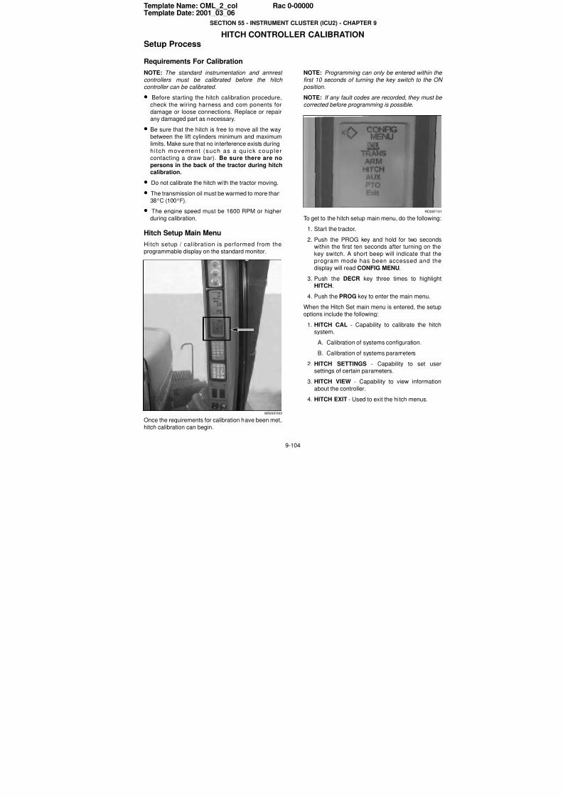
7/23/2019 Case Error Codes
http://slidepdf.com/reader/full/case-error-codes 104/140
9-104
Template Name: OML_2_col Rac 0-00000Template Date: 2001_03_06
SECTION 55 - INSTRUMENT CLUSTER (ICU2) - CHAPTER 9
HITCH CONTROLLER CALIBRATIONSetup Process
Requirements For Calibration
NOTE: The standard instrumentation and armrest
controllers must be calibrated before the hitch
controller can be calibrated.• Before starting the hitch calibration procedure,
check the wiring harness and com ponents for
damage or loose connections. Replace or repairany damaged part as necessary.
• Be sure that the hitch is free to move all the way
between the lift cylinders minimum and maximum
limits. Make sure that no interference exists during
hi tch movement (such as a quick couplercontacting a draw bar). Be sure there are no
persons in the back of the tractor during hitchcalibration.
• Do not calibrate the hitch with the tractor moving.
• The transmission oil must be warmed to more than
38°C (100°F).
• The engine speed must be 1600 RPM or higher
during calibration.
Hitch Setup Main Menu
Hitch setup / calibration is performed from the
programmable display on the standard monitor.
MD05F002
Once the requirements for calibration have been met,
hitch calibration can begin.
NOTE: Programming can only be entered within the
first 10 seconds of turning the key switch to the ON
position.NOTE: If any fault codes are recorded, they must be
corrected before programming is possible.
RD05F10
To get to the hitch setup main menu, do the following
1. Start the tractor.
2. Push the PROG key and hold for two secondswithin the first ten seconds after turning on the
key switch. A short beep will indicate that theprogram mode has been accessed and the
display will read CONFIG MENU.3. Push the DECR key three times to highligh
HITCH.
4. Push the PROG key to enter the main menu.
When the Hitch Set main menu is entered, the setup
options include the following:
1. HITCH CAL - Capability to calibrate the hitchsystem.
A. Calibration of systems configuration.
B. Calibration of systems parameters
2. HITCH SETTINGS - Capability to set usersettings of certain parameters.
3. HITCH VIEW - Capability to view information
about the controller.
4. HITCH EXIT - Used to exit the hitch menus.
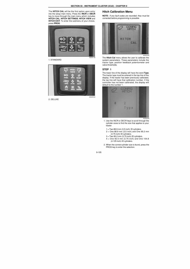
7/23/2019 Case Error Codes
http://slidepdf.com/reader/full/case-error-codes 105/140
SECTION 55 - INSTRUMENT CLUSTER (ICU2) - CHAPTER 9
9-105
The HITCH CAL will be the first option upon entry
into the setup main menu. Press the INCR or DECRkey to move through the main menu which includes
HITCH CAL, HITCH SETTINGS, HITCH VIEW andHITCH EXIT. To enter the submenu of your choice,
press PROG.
MD05F183
1. STANDARD
MD05F003
2. DELUXE
Hitch Calibration Menu
NOTE: If any fault codes are recorded, they must be
corrected before programming is possible.
MD05F04
The Hitch Cal menu allows the user to calibrate the
system parameters. These parameters include thetractor type, position feedback potentiometer and
valve thresholds.
STEP 1
The lower line of the display will have the word Type
The tractor type must be entered in the top line of thedisplay. If the tractor has been previously calibrated
the top line will have that calibration number. If thecontroller has not been calibrated, the display wil
default to the number 1.
RD05G04
1. Use the INCR or DECR keys to scroll through thecylinder sizes to find the size that applies to your
tractor.
1 = Two 88.9 mm (3.5 inch) ID cylinders.
2 = One 88.9 mm (3.5 inch) and One 95.2 mm
(3.75 inch) ID cylinders.3 = Two 95.2 mm (3.75 inch) ID cylinders.
4 = One 92.5 mm (3.75 inch) and One 104.8(4.125 inch) ID cylinders.
2. When the correct cylinder size is found, press the
PROG key to enter the selection.
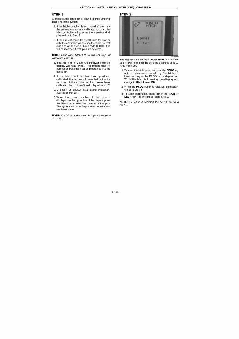
7/23/2019 Case Error Codes
http://slidepdf.com/reader/full/case-error-codes 106/140
SECTION 55 - INSTRUMENT CLUSTER (ICU2) - CHAPTER 9
9-106
STEP 2
At this step, the controller is looking for the number of
draft pins in the system.
1. If the hitch controller detects two draft pins, and
the armrest controller is calibrated for draft, the
hitch controller will assume there are two draftpins and go to Step 3.
2. If the armrest controller is calibrated for position
only, the controller will assume there are no draftpins and go to Step 3. Fault code HITCH 9313
will be recorded if draft pins are detected.
NOTE: Fault code HITCH 9313 will not stop the
calibration process.
3. If neither item 1 or 2 are true, the lower line of the
display will read “Pins”. This means that thenumber of draft pins must be programed into the
controller.
4. If the hitch controller has been previouslycalibrated, the top line will have that calibration
number. I f the control ler has never been
calibrated, the top line of the display will read “0”.
5. Use the INCR or DECR keys to scroll through the
number of draft pins.
6. When the correct number of draft pins isdisplayed on the upper line of the display, press
the PROG key to select that number of draft pins.
The system will go to Step 3 after the selectionhas been made
NOTE: If a failure is detected, the system will go to Step 10.
STEP 3
MD05F179
The display will now read Lower Hitch. It will allowyou to lower the hitch. Be sure the engine is at 1600
RPM minimum.
1. To lower the hitch, press and hold the PROG keyuntil the hitch lowers completely. The hitch will
lower as long as the PROG key is depressed.While the hitch is lowering, the display will
change to Hitch Lower ON.
2. When the PROG button is released, the systemwill go to Step 4.
3. To abort calibration, press either the INCR or
DECR key. The system will go to Step 9.
NOTE: If a failure is detected, the system will go to Step 9.
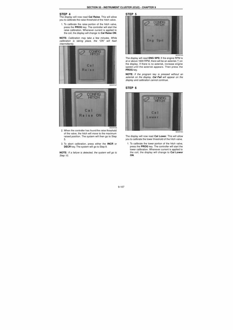
7/23/2019 Case Error Codes
http://slidepdf.com/reader/full/case-error-codes 107/140
SECTION 55 - INSTRUMENT CLUSTER (ICU2) - CHAPTER 9
9-107
STEP 4The display will now read Cal Raise. This will allowyou to calibrate the raise threshold of the hitch valve.
1. To calibrate the raise portion of the hitch valve,
press the PROG key. The controller will start theraise calibration. Whenever current is applied to
the coil, the display will change to Cal Raise ON.
NOTE: Calibration may take a few minutes. While calibration is taking place, the “ON” will flash
intermittently.
MD05F047
MD05F048
2. When the controller has found the raise threshold
of the valve, the hitch will move to the maximumraised position. The system will then go to Step
5.
3. To abort calibration, press either the INCR orDECR key. The system will go to Step 9.
NOTE: If a failure is detected, the system will go to
Step 10.
STEP 5
MD05F04
The display will read ENG SPD. If the engine RPM isat or above 1600 RPM, there will be an asterisk (*) on
the display. If there is no asterisk, increase enginespeed until the asterisk appears. Then press the
PROG key.
NOTE: If the program key is pressed without anasterisk on the display, Cal Fail will appear on the
display and calibration cannot continue.
STEP 6
MD05F05
The display will now read Cal Lower. This will allow
you to calibrate the lower threshold of the hitch valve
1. To calibrate the lower portion of the hitch valvepress the PROG key. The controller will start the
lower calibration. Whenever current is applied tothe coil, the display will change to Cal Lower
ON.
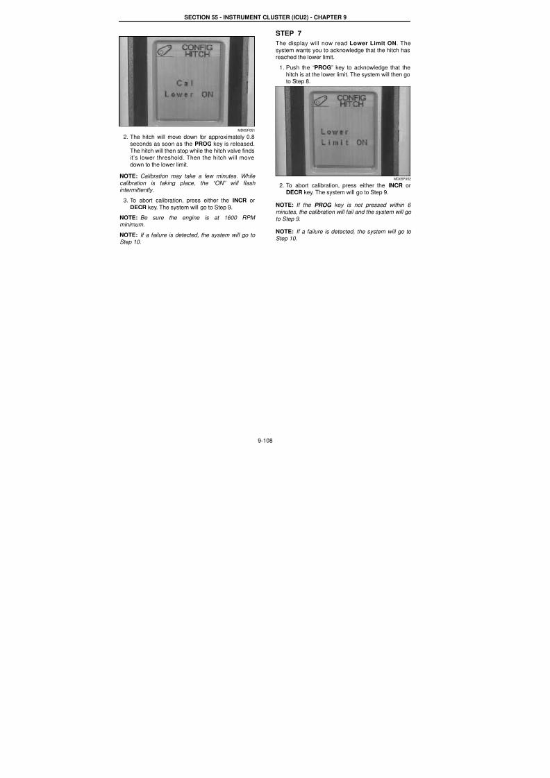
7/23/2019 Case Error Codes
http://slidepdf.com/reader/full/case-error-codes 108/140
SECTION 55 - INSTRUMENT CLUSTER (ICU2) - CHAPTER 9
9-108
MD05F051
2. The hitch will move down for approximately 0.8seconds as soon as the PROG key is released.
The hitch will then stop while the hitch valve findsit’s lower threshold. Then the hitch will move
down to the lower limit.
NOTE: Calibration may take a few minutes. While calibration is taking place, the “ON” will flash intermittently.
3. To abort calibration, press either the INCR or
DECR key. The system will go to Step 9.
NOTE: Be sure the engine is at 1600 RPM
minimum.
NOTE: If a failure is detected, the system will go to
Step 10.
STEP 7
The display will now read Lower Limit ON. The
system wants you to acknowledge that the hitch hasreached the lower limit.
1. Push the “PROG” key to acknowledge that the
hitch is at the lower limit. The system will then goto Step 8.
MD05F052
2. To abort calibration, press either the INCR orDECR key. The system will go to Step 9.
NOTE: If the PROG key is not pressed within 6
minutes, the calibration will fail and the system will go
to Step 9.
NOTE: If a failure is detected, the system will go to Step 10.

7/23/2019 Case Error Codes
http://slidepdf.com/reader/full/case-error-codes 109/140
SECTION 55 - INSTRUMENT CLUSTER (ICU2) - CHAPTER 9
9-109
STEP 8
MD05F053
The display will now read Cal Done. This indicatesthat hitch cal ibrat ion has been successful ly
completed.
1. Press the PROG key to return to the hitch mainmenu.
MD05F045
MD05F063
2. HITCH CAL will be on the display. Press theINCR key to go to HITCH EXIT menu. Press the
PROG key to exit calibration.
STEP 9
If the display reads Cal Aborted. This means tha
the calibration process was aborted at some point.
1. Press the PROG key to return to the main menu
2. There are several things that can cause the
calibration to be aborted.
A. The tractor starts moving.
B. No engine speed.
C. The operator aborted calibration.
STEP 10
When the display reads Cal Fail, it means that a
failure has occurred during the calibration process
The controller will now be in the halt mode.
1. Press the PROG key to go back to the main
menu.
NOTE: Entry into hitch calibration will not be alloweduntil the key switch has been cycled OFF, then ON.
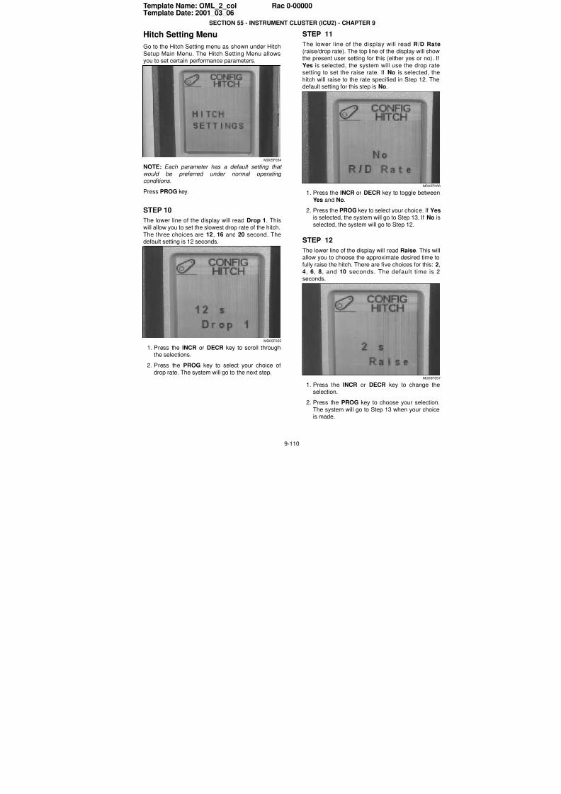
7/23/2019 Case Error Codes
http://slidepdf.com/reader/full/case-error-codes 110/140
9-110
Template Name: OML_2_col Rac 0-00000Template Date: 2001_03_06
SECTION 55 - INSTRUMENT CLUSTER (ICU2) - CHAPTER 9
Hitch Setting Menu
Go to the Hitch Setting menu as shown under Hitch
Setup Main Menu. The Hitch Setting Menu allowsyou to set certain performance parameters.
MD05F054
NOTE: Each parameter has a default setting that
would be preferred under normal operating
conditions.
Press PROG key.
STEP 10
The lower line of the display will read Drop 1. This
will allow you to set the slowest drop rate of the hitch.
The three choices are 12, 16 and 20 second. Thedefault setting is 12 seconds.
MD05F055
1. Press the INCR or DECR key to scroll throughthe selections.
2. Press the PROG key to select your choice of
drop rate. The system will go to the next step.
STEP 11
The lower line of the display will read R/D Rate
(raise/drop rate). The top line of the display will showthe present user setting for this (either yes or no). I
Yes is selected, the system will use the drop ratesetting to set the raise rate. If No is selected, the
hitch will raise to the rate specified in Step 12. The
default setting for this step is No.
MD05F05
1. Press the INCR or DECR key to toggle between
Yes and No.
2. Press the PROG key to select your choice. If Yes
is selected, the system will go to Step 13. If No is
selected, the system will go to Step 12.
STEP 12
The lower line of the display will read Raise. This wilallow you to choose the approximate desired time to
fully raise the hitch. There are five choices for this: 2
4, 6, 8, and 10 seconds. The default time is 2seconds.
MD05F05
1. Press the INCR or DECR key to change theselection.
2. Press the PROG key to choose your selection
The system will go to Step 13 when your choiceis made.
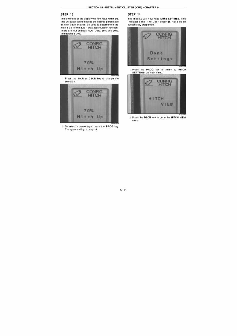
7/23/2019 Case Error Codes
http://slidepdf.com/reader/full/case-error-codes 111/140
SECTION 55 - INSTRUMENT CLUSTER (ICU2) - CHAPTER 9
9-111
STEP 13
The lower line of the display will now read Hitch Up.
This will allow you to choose the desired percentageof hitch travel that will be used to determine if the
hitch is up for the auto - area accumulation function.There are four choices: 60%, 70%, 80% and 90%.
The default is 70%.
MD05F058
1. Press the INCR or DECR key to change the
selection.
MD05F058
2. To select a percentage, press the PROG key.The system will go to step 14.
STEP 14
The display will now read Done Settings. This
ind ica tes tha t the user se t t ings have beensuccessfully programed.
MD05F05
1. Press the PROG key to return to HITCHSETTINGS, the main menu.
MD05F06
2. Press the DECR key to go to the HITCH VIEW
menu.
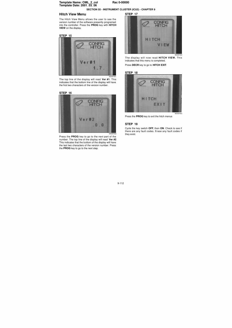
7/23/2019 Case Error Codes
http://slidepdf.com/reader/full/case-error-codes 112/140
9-112
Template Name: OML_2_col Rac 0-00000Template Date: 2001_03_06
SECTION 55 - INSTRUMENT CLUSTER (ICU2) - CHAPTER 9
Hitch View Menu
The Hitch View Menu allows the user to see the
version number of the software presently programedinto the controller. Press the PROG key with HITCH
VIEW on the display.
STEP 15
MD05F061
The top line of the display will read Ver #1. This
indicates that the bottom line of the display will havethe first two characters of the version number.
STEP 16
MD05F062
Press the PROG key to go to the next part of the
number. The top line of the display will read Ver #2This indicates that the bottom of the display will have
the last two characters of the version number. Press
the PROG key to go to the next step.
STEP 17
MD05F06
The display will now read HITCH VIEW. Thisindicates that this menu is completed.
Press DECR key to go to HITCH EXIT.
STEP 18
MD05F06
Press the PROG key to exit the hitch menus
STEP 19
Cycle the key switch OFF, then ON. Check to see ithere are any fault codes. Erase any fault codes i
they exist.
7/23/2019 Case Error Codes
http://slidepdf.com/reader/full/case-error-codes 113/140
9-113
Template Name: OML_2_col Rac 0-00000Template Date: 2001_03_06
SECTION 55 - INSTRUMENT CLUSTER (ICU2) - CHAPTER 9
HITCH CONTROLLER FAULT CODESFAULT CODE HITCH 3010
Transmission Speed Sensor Failed
Cause:The Data Bus signaled that the transmission speed sensor has failed.
The hitch controller received the signal from the instrumentation controller.
Possible failure mode:1. The transmission speed sensor failed (in most cases).
2. Software execution error in instrumentation controller (small chance).
Solution:The speed sensor is hard wired to the instrumentation controller. The instrumentation controller sends the whee
(transmission) speed signal to the hitch controller and the PTO controller by way of the Data Bus.
If the sensor or the instrumentation controller has problem, both fault code HITCH 3010 and PTO 54060 should
appear. If only HITCH 3010 is recorded, the problem is more likely with the hitch controller.
1. If the service tool is connected to the tractor, do the following:Go to the Monitor screen, click the Monitor Icon.
Click the CHANGE PARAMETER SELECTIONS Icon.
Select the INST GROUND SPEED - WHEEL and then ADD.You will be able to monitor the wheel speed sensor signal on the screen.
Drive the tractor and watch the signal change when the tractor speed changes.If there is no wheel speed signal, go to step 2.
If there is wheel speed signal, compare it to the speed display on the instrumentation cluster.If the speed signal looks fine on service tool but not on the instrumentation cluster, it is more likely a problem
with the instrumentation cluster.
If both signals seem fine, check the function of the hitch controller.
2. Test the resistance of the transmission speed sensor:
Locate the transmission speed sensor on top of the transmission.
Disconnect connector C069 from the sensor.Inspect the connector. Clean the connection.
Measure the sensor resistance between pin A and Pin B.
The resistance should be around 3 k ohms at 20 degree Celsius.If the resistance is not in the specified range, replace the transmission speed sensor.If it is as specified, go to next step.
3. Check the wiring from the transmission speed sensor to connector C060 and then to connector CN2 at the
instrumentation controller.There should be a 5 VDC power supply from pin 12 of CN1 to pin A of connector C069 when the tractor key is
in the ‘RUN’ position.
There should be good continuity from pin B of connector C069 to the clean ground.Check for open circuit and wiring shortage.
NOTE: Always inspect connector ends for damage, bent or dislocated pins when troubleshooting.
4. If none of above, check the function of the instrumentation controller and the hitch controller.
NOTE: Also see the Data Bus schematic foldout at the end of this section.
NOTE: See schematic sections 24, 25 and 26 at the rear of this section.
7/23/2019 Case Error Codes
http://slidepdf.com/reader/full/case-error-codes 114/140
SECTION 55 - INSTRUMENT CLUSTER (ICU2) - CHAPTER 9
9-114
FAULT CODE HITCH 12041Communication Lost With The Instrument Controller
Cause:
The hitch controller is not receiving or recognizing information from the instrumentation controller.
Possible failure codes:
1. Bad connection between hitch controller and the instrument controller.
2. Controller failure.Solution:
Make sure both the instrument controller and the hitch controller functioning OK.
Check the Data Bus connections.
1. Check the function of the hitch controller.
a) Make sure the connector to the hitch controller is plugged in.
b) Check the LED light on the hitch controller.LED light on - failed controller, replace the controller.
LED light flashing - controller is OK.LED off - no power to controller, check power supply and its fuse.
2. Check the function of the instrument controller.
a) If there is no display and no back light on the tractor instrumentation, it is more likely that there is no powerto controller. Check power supply, its fuse, and the ground to the controller. Make sure the connector CN2 to
the instrument controller is plugged in.b) If there is a display on the tractor instrumentation but the display is erratic, such as unusual symbols, and
other controllers claim communication is lost with the instrument controller, it is likely that the instrument
controller has failed. Replace the controller.c) If nothing can be found wrong with the instrument controller, go to step 3.
3. Check the power supply to the Data Bus.
The power supply to the Data Bus is from the switched power through Fuse #41.a) Make sure Fuse #41 is not burned out.
b) Turn the tractor Key ’ON’. Check the power supply at Fuse #41. There should be 12 volts.If not, check the power supply from the switched power.
4. Check the integrity of Data Bus at the passive terminators.The following checks are basically looking into one end of the bus and check the terminator at the other end.a) Check from the passive terminator at the rear of the tractor.
Disconnect the terminator at connector C175.
With the key on, measure the voltage on the wires connected to C175.At pin 1, the red wire, it should read 12 volts battery voltage.
At pin 2, the yellow wire, it should read 2.5 to 4 volts (2.5 V nominally).At pin 3, there should be continuity from pin 3 to the clean ground.
At pin 4, the green wire, it should read 2.5 to 1 volts (2.5 V nominally).If the above checks are OK, it means that the front terminator and data bus wiring is OK.
If not, go to next step.
b) Check from the passive terminator at the front of the tractor.Reconnect the rear terminator and disconnect the front terminator at connector C205.
With the key on, measure the voltage on the wires connected to C205.At pin 1, the red wire, it should read 12 volts battery voltage.
At pin 2, the yellow wire, it should read 2.5 to 4 volts (2.5 V nominally).At pin 3, there should be continuity from pin 3 to the clean ground.
At pin 4, the green wire, it should read 2.5 to 1 volts (2.5 V nominally).
If the above checks are OK, it means that the front terminator and data bus wiring is OK.If not, check for bad connection and damaged wire along the Data Bus.

7/23/2019 Case Error Codes
http://slidepdf.com/reader/full/case-error-codes 115/140
SECTION 55 - INSTRUMENT CLUSTER (ICU2) - CHAPTER 9
9-115
NOTE: When there is a bad connection along the Data Bus wiring, the fault code will be accompanied by multiple
fault codes such as TRANS 12011, PTO 54120, INST 12011, AUX 12011, INST 12031, TRANS 12031 and PTO54140.
NOTE: Always inspect connector ends for damaged, bent or dislocated pins when troubleshooting.
NOTE: Also see the Data Bus schematic foldouts 12 through 18 at the end of this section.
NOTE: See schematic sections 24, 51 and 52 at the rear of this section.
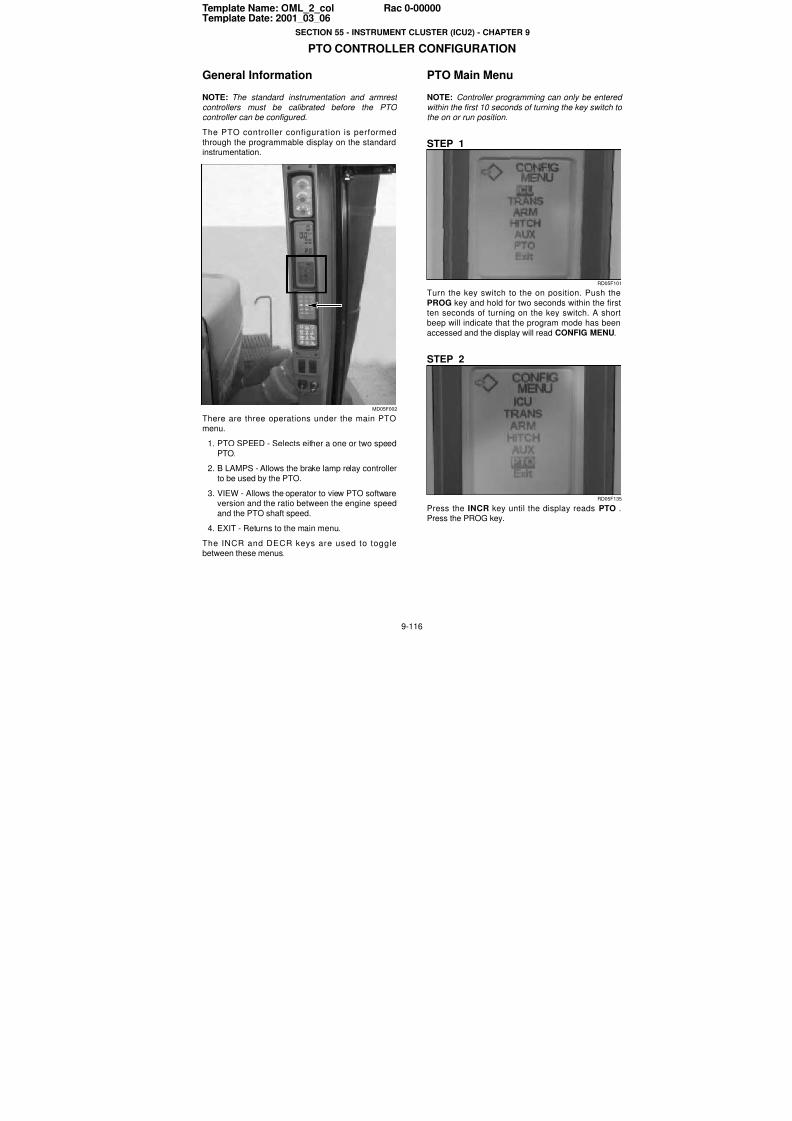
7/23/2019 Case Error Codes
http://slidepdf.com/reader/full/case-error-codes 116/140
9-116
Template Name: OML_2_col Rac 0-00000Template Date: 2001_03_06
SECTION 55 - INSTRUMENT CLUSTER (ICU2) - CHAPTER 9
PTO CONTROLLER CONFIGURATION
General Information
NOTE: The standard instrumentation and armrest
controllers must be calibrated before the PTO controller can be configured.
The PTO controller configuration is performed
through the programmable display on the standardinstrumentation.
MD05F002
There are three operations under the main PTOmenu.
1. PTO SPEED - Selects either a one or two speed
PTO.
2. B LAMPS - Allows the brake lamp relay controller
to be used by the PTO.
3. VIEW - Allows the operator to view PTO software
version and the ratio between the engine speedand the PTO shaft speed.
4. EXIT - Returns to the main menu.
The INCR and DECR keys are used to togglebetween these menus.
PTO Main Menu
NOTE: Controller programming can only be entered
within the first 10 seconds of turning the key switch tothe on or run position.
STEP 1
RD05F10
Turn the key switch to the on position. Push the
PROG key and hold for two seconds within the firsten seconds of turning on the key switch. A shor
beep will indicate that the program mode has been
accessed and the display will read CONFIG MENU.
STEP 2
RD05F13
Press the INCR key until the display reads PTO Press the PROG key.
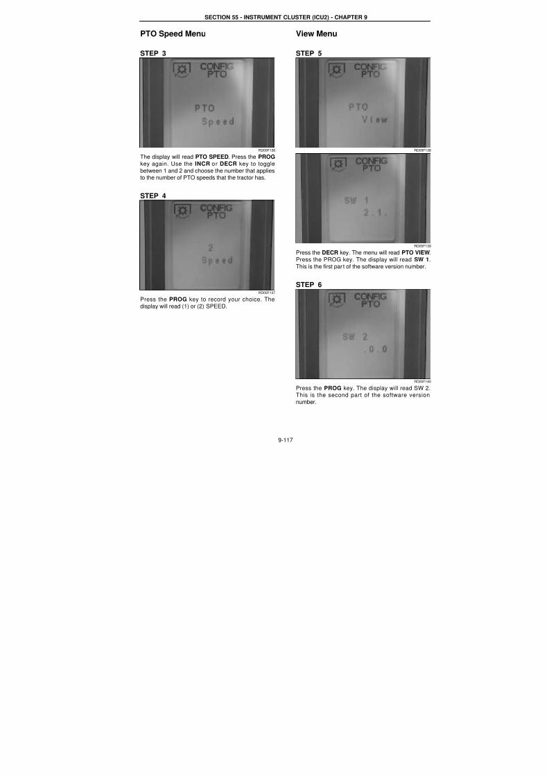
7/23/2019 Case Error Codes
http://slidepdf.com/reader/full/case-error-codes 117/140
SECTION 55 - INSTRUMENT CLUSTER (ICU2) - CHAPTER 9
9-117
PTO Speed Menu
STEP 3
RD05F136
The display will read PTO SPEED. Press the PROG
key again. Use the INCR or DECR key to toggle
between 1 and 2 and choose the number that applies
to the number of PTO speeds that the tractor has.
STEP 4
RD05F137
Press the PROG key to record your choice. The
display will read (1) or (2) SPEED.
View Menu
STEP 5
RD05F13
RD05F13
Press the DECR key. The menu will read PTO VIEW
Press the PROG key. The display will read SW 1
This is the first par t of the software version number.
STEP 6
RD05F14
Press the PROG key. The display will read SW 2This is the second part of the software version
number.

7/23/2019 Case Error Codes
http://slidepdf.com/reader/full/case-error-codes 118/140
SECTION 55 - INSTRUMENT CLUSTER (ICU2) - CHAPTER 9
9-118
STEP 7
RD05F138
RD05F141
Press the PROG key. The display will read PTOVIEW. Press The DECR key and the display will read
PTO EXIT. Pressing the PROG key will exit from PTOconfiguration.
7/23/2019 Case Error Codes
http://slidepdf.com/reader/full/case-error-codes 119/140
9-119
Template Name: OML_2_col Rac 0-00000Template Date: 2001_03_06
SECTION 55 - INSTRUMENT CLUSTER (ICU2) - CHAPTER 9
SYMPTOM BASED FAULTS - NO FAULT CODES
PTO Will Not Engage -- “TURN PTO OFF” Is On Display
Meaning:
The PTO will not turn when PTO switch is placed in the ON position and no fault codes are recorded.
Possible failure mode:
1. PTO controller is not reading engine RPM at PIN C056-1 (Gray) from the alternator.2. The 12 volt power supply wire or the PTO solenoid failed OPEN (Pin C057-4 Black connector).
3. Problem with PTO solenoid circuit.
Background:
The PTO controller looks at engine speed from the alternator and PTO output shaft speed before and after the PTO
switch is turned on. The PTO controller will engage the PTO solenoid just enough to start shaft rotation. Once shaftrotation is detected the PTO controller will control clutch modulation and run up speed for several seconds before
full clutch pressure is applied. If the PTO controller fails to receive information from the PTO solenoid circuitalternator (engine RPM) or output shaft speed sensor, the PTO will not engage.
Tractors with an engine controller
-- The engine controller will provide engine RPM to the display when the alternator fails but not to the PTOcontroller, therefore the PTO will not engage when the PTO is turned on if the alternator fails.
-- If the PTO solenoid circuit is failed open, no fault code is recorded.-- Problem with PTO solenoid.
Tractors without a engine controller
-- The alternator provides engine RPM to the display and to the PTO controller. The transmission controller uses
data bus information from the instrumentation controller. When the alternator fails the PTO and the transmissionwill not engage. Engine RPM will not be displayed on the instrumentation display.
-- If the PTO solenoid circuit is failed open no fault code is recorded.-- Problem with PTO solenoid.
PTO solenoid resistance
PTO solenoid 6.0 - 6.8 ohms at 25 C (70 F).
Wiring information:
NOTE: Always inspect connector ends for damaged or bent or dislocated pins when troubleshooting.C057-5 --> C159-B (PTO solenoid) C159-A --> C057-4
Alternator (W) --> C085 --> C333-12 --> Splice--> C060-12 -->CN1-19 (instrument cluster)
Corrective action:
STEP 1 - Alternator checkClear all fault codes.
Start the tractor and check the display for engine RPM (Tractors without a engine controller).Turn PTO ON and then OFF.
Check for PTO fault codes.
-- NOT OK - PTO did not turn and PTO fault code 54261 is recorded, go to Step 3 (Tractor with engine controller).-- NOT OK - No engine RPM read on display, Go to Step 2 (Tractors with no engine controller).
-- NOT OK - No PTO fault codes and PTO will not turn, Go to Step 3.-- NOT OK - A new PTO fault code was record, go to new fault code for corrective action.
STEP 2 - Check the alternatorCheck alternator output at terminal “W”.-- OK - Go to Step 3.
-- NOT OK - Replace alternator.

7/23/2019 Case Error Codes
http://slidepdf.com/reader/full/case-error-codes 120/140
SECTION 55 - INSTRUMENT CLUSTER (ICU2) - CHAPTER 9
9-120
STEP 3 - Check wiringRemove the controller cover from the rear of the tractor.Check the wire and connections between the alternator terminal “W” and the PTO controller pin C056-1 for an open
circuit.
NOTE: A test wire can be run from the alternator terminal “W” to the PTO controller pin C056-1.
STEP 4 - Check PTO solenoid circuitDisconnect Connector C057
Measure the resistance between pin C057-5 and C057-4.-- OK - Resistance measured was between 6.0 and 6.8 ohms at 25 C (100 F).
-- NOT OK - The resistance was not between 6.0 to 6.8 ohms, go to Step 5.
STEP 5 - Test solenoidDisconnect PTO solenoid at connect C0159.
Measure the resistance of the PTO solenoid.
Inspect connector pins.
-- OK - Replace damaged wire.
-- NOT OK - Replace PTO solenoid.
7/23/2019 Case Error Codes
http://slidepdf.com/reader/full/case-error-codes 121/140
SECTION 55 - INSTRUMENT CLUSTER (ICU2) - CHAPTER 9
9-121
PTO CONTROLLER FAULT CODESFAULT CODE PTO 54050
Wheel Slip Sensing Error In The Instrumentation Controller
Cause:The percent slip is decided by the difference between the wheel speed and the ground speed. The hitch controlle
receives the slip signal information from the instrumentation controller through the Data Bus.
Possible failure mode:1. Wheel slip sensing (radar gun, wheel speed sensor) failed (in most cases).
2. Percent slip calculation failed in instrumentation controller (small chance).
RADAR FUNCTIONThe radar is connected to the vehicle electrical system through a 4 pin connector.
Pin A: GND
Pin B: SIG,
Pin C: B+
Pin D: PresentPin A is the radar ground. Which is connected to the vehicle clean ground through SPL-F1.
Pin B is the radar signal. The signal is of square wave form with ’Low’ 0.8 VDC or less and ’High’ 3.7VDC minimumIts frequency is scaled to 44 HZ/mph and proportional to ground speed. The signal is connected to the ICU pin 13
CN1 through connector C060 Pin 25.Pin C is the power supply to the radar from Fuse 34 through connector C010 pin 83.
Pin D is the signal from radar to ICU indicating radar is connected to the system. It is connected to the ICU Pin 13
through connector C060 Pin 28.
Solution:
The wheel speed sensor and the radar gun (for the ground speed) are hard wired to instrumentation controller. If
the problem is with the wheel speed sender, then fault code HITCH 3010 and PTO 54060 should be recorded.
If there is no HITCH 3010 and PTO 54060, the problem is most likely with the radar gun. There is also a smalchance of instrumentation controller malfunction.
1. Check the wiring of radar gun.
Disconnect connector C068 at the radar.
The power supply at pin C of connector C068 should be about 5 VDC when the tractor key is in the ’RUN’position.There should be good continuity from pin A of connector C068 to the clean ground.
Check for open circuit and wiring shortage.
2. Check the function of the radar.The signal is from Pin B of the radar and connected to the pin 13 of the instrument cluster through Pin 25 of
connector C060. The radar will detect the speed of any thing moving in front of it. So a quick hand moving in
front of the radar will be an easy way to test the frequency change of the radar signal. Special tools (such asoscilloscope) is needed to check the frequency.
If the radar does not work as expected, replace the radar in the following procedures:a. Disconnect the radar wiring.
b. Remove the radar from the vehicle.
c. Install the new radar.d. Reconnect the wiring and check the function of the new radar.
3. If there is no problem with the radar and its wiring, check the function of the instrumentation controller and the
hitch controller.
NOTE: Always inspect connector ends for damaged, bent or dislocated pins when troubleshooting.
NOTE: See schematic sections 24,25 and 26 at the rear of this section.
7/23/2019 Case Error Codes
http://slidepdf.com/reader/full/case-error-codes 122/140
SECTION 55 - INSTRUMENT CLUSTER (ICU2) - CHAPTER 9
9-122
FAULT CODE PTO 54060Ground Speed Signal Failed In The Instrumentation Controller
Cause:
The Data Bus signaled that the transmission speed sensor has failed.The PTO controller received the signal from the instrumentation controller.
Possible failure mode:
1. The transmission speed sensor failed (in most cases).2. Software execution error in instrumentation controller (small chance).
WHEEL SPEED SENSOR INFORMATION
Cavity A: SignalCavity B: Ground
Operating Temperature: - 40 degree C to 125 degree C
Resistance: 2700 to 3300 ohmsInductance: 1.9 to 2.9 H
Output: 30 Hz to 7 kHz Quasi-Sinusoidal
Solution:The speed sensor is hard wired to the instrumentation controller. The instrumentation controller sends the wheel
(transmission) speed signal to the hitch controller and the PTO controller via Data Bus.
If the sensor or the instrumentation controller has a problem, both fault code HITCH 3010 and PTO 54060 shouldappear. If only PTO 54060 is recorded, the problem is most likely with the PTO controller.
1. If the service tool is connected to the tractor, do the following:
Go to the Monitor screen by clicking on the Monitor Icon.Click the CHANGE PARAMETER SELECTIONS Icon.
Select the INST GROUND SPEED - WHEEL and then ADD.
You will be able to monitor the wheel speed sensor signal on the screen.Drive the tractor and watch the signal change when the tractor speed changes.
If there is no wheel speed signal, go to step 2.If there is wheel speed signal, compare it to the speed display on the instrumentation cluster.
If the speed signal looks fine on service tool but not on the instrumentation cluster, it is more likely a problem
with the instrumentation cluster.If both signals seem fine, check the function of the PTO controller.
2. Test the resistance of the transmission speed sensor:
Locate the transmission speed sensor on top of the transmission.Disconnect connector C069 from the sensor.
Inspect the connector. Clean the connection.Measure the sensor resistance between pin A and Pin B.
The resistance should be around 3 k ohms at 20 degree celsius.If the resistance is not in the specified range, replace the transmission speed sensor.
If it is as specified, go to next step.
3. Check the wiring from the transmission speed sensor to connector C060 and then to connector CN1 at the
instrumentation controller.There should be 5 VDC power supply from pin 12 of CN1 to pin A of connector C069 when the tractor key is in
the ’RUN’ position.There should be good continuity from pin B of connector C069 to the clean ground.
Check for open circuit and wiring shortage.
4. If none of above, check the function of the instrumentation controller and the PTO controller.
NOTE: Always inspect connector ends for damaged, bent or dislocated pins when troubleshooting.
NOTE: See schematic sections 24,25 and 26 and 12 thru 18 at the rear of this section.
7/23/2019 Case Error Codes
http://slidepdf.com/reader/full/case-error-codes 123/140
SECTION 55 - INSTRUMENT CLUSTER (ICU2) - CHAPTER 9
9-123
FAULT CODE PTO 54130Communication Lost With The Instrumentation Controller
Cause:
Communication lost between PTO controller and instrumentation controller.
Possible failure mode:
1. Bad connection between PTO controller and instrumentation controller.
2. Controller failure.
Solution:Make sure both the instrumentation controller and the PTO controller are functioning OK.
Check the Data Bus connections.
1. Check the function of the PTO controller:a) Make sure the connector (C056) to the PTO controller is plugged in.
b) Check the LED lamp on the PTO controller.LED lamp on - failed controller, replace the controller.
LED lamp flashing - controller is OK.
LED off - no power to controller, check power supply and its fuse.
2. Check the function of the Instrument controller:
a) If there is no display and no back light on the tractor instrumentation, it is most likely that there is no power tothe controller. Check the power supply, its fuse, and the ground to the controller. Make sure the connector CN2to the instrument controller is plugged in.
b) If there is display on the tractor instrumentation but the display is erratic, such as unusual symbols, and othecontrollers claim communication lost with the instrument controller, it is most likely the instrument controller has
failed. Replace the controller.c) If nothing wrong can be found with the instrument controller, go to step 3.
3. Check the power supply to the Data Bus.
The power supply to the Data Bus is from the switched power through Fuse #41.a) Make sure Fuse #41 is not burned out.
b) Turn the tractor key ’ON’. Check the power supply at Fuse #41. There should be 12 volts.
If not, check the power supply from the switched power.
4. Check the integrity of Data Bus at the passive terminatorsThe following checks are basically looking into one end of the data ,bus and checking the terminator at the
other end.a) Check from the passive terminator at the rear of the tractor.
Disconnect the terminator at connector C175.With the key on, measure the voltage on the wires connected to C175.
At pin 1, the red wire, it should read 12 volts battery voltage.
At pin 2, the yellow wire, it should read 2.5 to 4 volts (2.5 V nominally).At pin 3, there should be continuity from pin 3 to the clean ground.
At pin 4, the green wire, it should read 2.5 to 1 volts (2.5 V nominally).If the above checks are OK, it means that the front terminator and data bus wiring is OK.
If not, go to next.
b) Check from the passive terminator at the front of the tractor.Reconnect the rear terminator and disconnect the front terminator at connector C205.
With the key on, measure the voltage on the wires connected to C205.At pin 1, the red wire, it should read 12 volts battery voltage.
At pin 2, the yellow wire, it should read 2.5 to 4 volts (2.5 V nominally).At pin 3, there should be continuity from pin 3 to the clean ground.
At pin 4, the green wire, it should read 2.5 to 1 volts (2.5 V nominally).If the above checks are OK, it means that the rear terminator and data bus wiring is OK.
If not, check for bad connection and damaged wire along the Data Bus.

7/23/2019 Case Error Codes
http://slidepdf.com/reader/full/case-error-codes 124/140
SECTION 55 - INSTRUMENT CLUSTER (ICU2) - CHAPTER 9
9-124
NOTE: When there is a bad connection along the Data Bus wiring, the fault code will be accompanied by multiple
fault codes such as TRANS 12011, PTO 54120, INST 12011, AUX 12011, INST 12031, TRANS 12031 and PTO 54140.
NOTE: Always inspect connector ends for damaged, bent or dislocated pins when troubleshooting.
NOTE: See schematic sections 44,45 and 24 at the rear of this section.
NOTE: Also see the data bus schematic foldout at the end of this section.
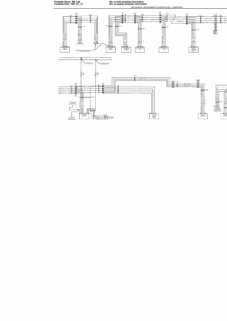
7/23/2019 Case Error Codes
http://slidepdf.com/reader/full/case-error-codes 125/140
Template Name: SM_foldTemplate Date: 1997_01_13
Alt= to hide template informationAlt+ to display template information
SECTION 55 - INSTRUMENT CLUSTER (ICU2) - CHAP

7/23/2019 Case Error Codes
http://slidepdf.com/reader/full/case-error-codes 126/140
9-126
PRINTER NOTE:
THIS PAGE IS BLANK
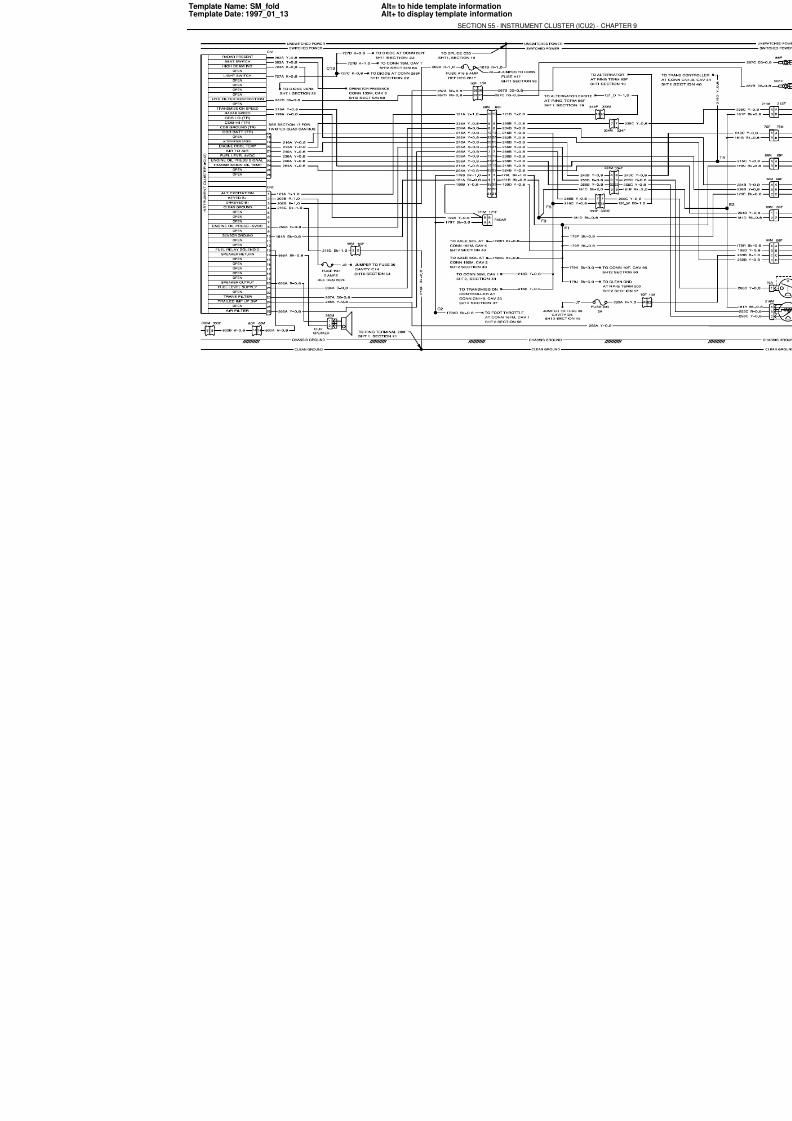
7/23/2019 Case Error Codes
http://slidepdf.com/reader/full/case-error-codes 127/140
Template Name: SM_foldTemplate Date: 1997_01_13
Alt= to hide template informationAlt+ to display template information
SECTION 55 - INSTRUMENT CLUSTER (ICU2) - CHAP

7/23/2019 Case Error Codes
http://slidepdf.com/reader/full/case-error-codes 128/140
9-128
PRINTER NOTE:
THIS PAGE IS BLANK
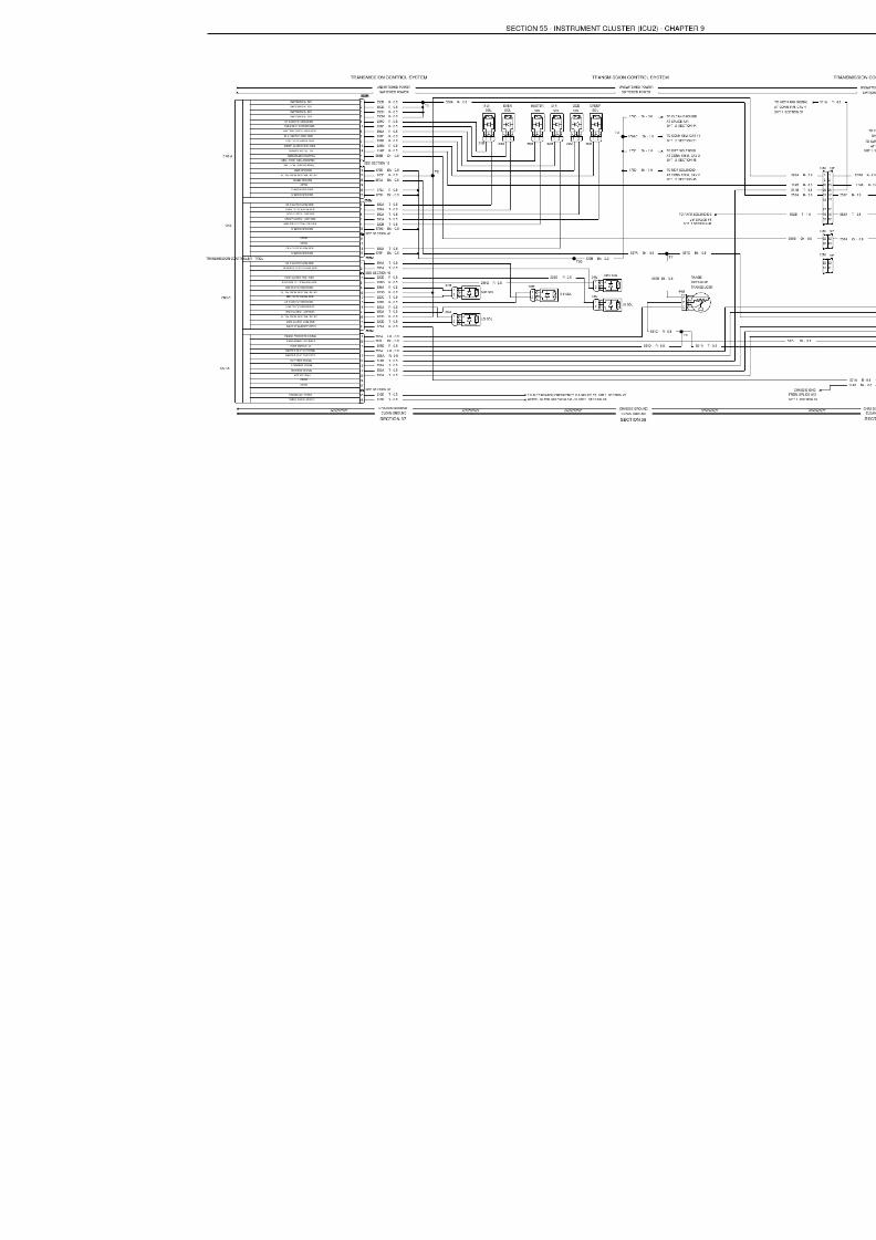
7/23/2019 Case Error Codes
http://slidepdf.com/reader/full/case-error-codes 129/140

7/23/2019 Case Error Codes
http://slidepdf.com/reader/full/case-error-codes 130/140
9-130
PRINTER NOTE:
THIS PAGE IS BLANK
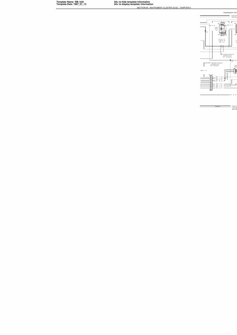
7/23/2019 Case Error Codes
http://slidepdf.com/reader/full/case-error-codes 131/140
Template Name: SM_foldTemplate Date: 1997_01_13
Alt= to hide template informationAlt+ to display template information
SECTION 55 - INSTRUMENT CLUSTER (ICU2) - CHAP

7/23/2019 Case Error Codes
http://slidepdf.com/reader/full/case-error-codes 132/140
9-132
PRINTER NOTE:
THIS PAGE IS BLANK
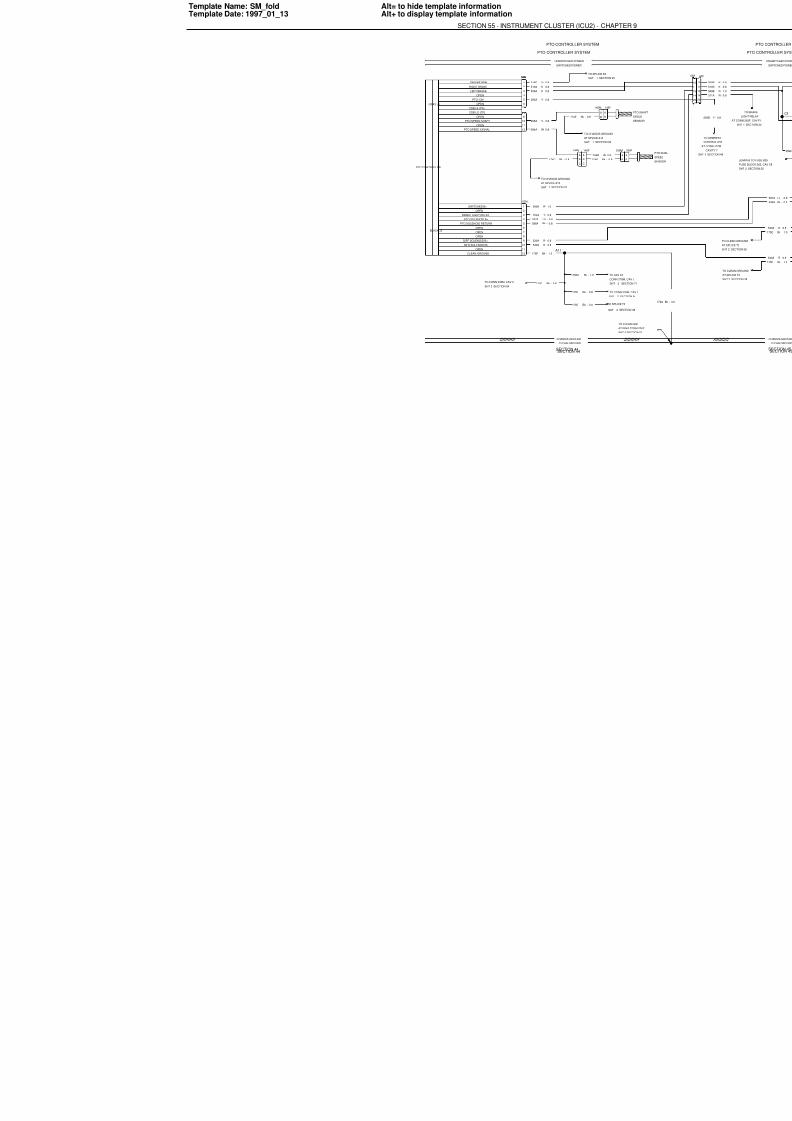
7/23/2019 Case Error Codes
http://slidepdf.com/reader/full/case-error-codes 133/140
Template Name: SM_foldTemplate Date: 1997_01_13
Alt= to hide template informationAlt+ to display template information
SECTION 55 - INSTRUMENT CLUSTER (ICU2) - CHAP
PTO CONTROLLER
GRAY J1
ENGINE RPM
RIGHT BRAKE
LEFT BRAKE
OPEN
PTO "ON"
OPEN
CDB HI (TR)
CDB LO (TR)
OPEN
PTO SPEED SHAFT
OPENPTO SPEED SIGNAL
BLACK J2
SWITCHED B+
OPEN
BRAKE LIGHT RELAY
PTO SOLENOID B+
PTO SOLENOID RETURN
OPEN
OPEN
OPEN
DIFF SOLENOID B+
MFD SOLENOID B+
OPEN
CLEAN GROUND
CHASSIS GROUND
CLEAN GROUND
UNSWITCHED POWER
SWITCHED POWER
PTO CONTROLLER SYSTEM
SECTION 44
1
2
3
4
5
6
56M
9
10
1112
56M
1
2
3
4
5
6
7
8
9
10
11
12
57M
B
A
145M
A
B
145F
C
B
A
146M
A
B
C
146F 336
A11
2SHT
CONN 2
TO AFS
2SHT
TO CON
2SHT
TO SPLIC
S
A
T
SECTION 321SHT
AT SPLICE A13
TO CHASSIS GROUND
SECTION 251SHT
TO SPLICE F6
0.8-Bk
174E
0.8-Bk
174C 0.8-Bk
174D
0.8-W
294B
0.8-W
294A
0.8-Y
295A
0.8-Y
293A
0.8-K
509A
0.8-K
510A
0.8-Y
216D
SECTION 321SHT
AT SPLICE A13
TO CHASSIS GROUND
0.8-T
702A
1.0-R
599A
0.8-LU
597A
0.8-R
540A
0.8-R
530A
0.8-Bk
598A
1.0-Bk
179F
SECTION 542SHT
TO CONN 335M, CAV 3
1.0-Bk
179BJ
0.8-Bk
179G
0.8-Bk
179H
3.0-Bk
179C
SECTION 44
PTO CONTROLLER SYSTEM

7/23/2019 Case Error Codes
http://slidepdf.com/reader/full/case-error-codes 134/140
9-134
PRINTER NOTE:
THIS PAGE IS BLANK
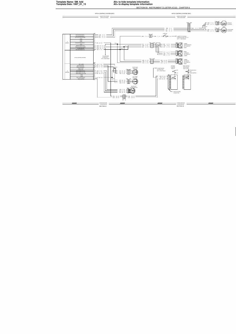
7/23/2019 Case Error Codes
http://slidepdf.com/reader/full/case-error-codes 135/140
Template Name: SM_foldTemplate Date: 1997_01_13
Alt= to hide template informationAlt+ to display template information
SECTION 55 - INSTRUMENT CLUSTER (ICU2) - CHAP
HITCH CONTROLLER (EDC)
HITCH SOLENOID B+
HITCH SOLENOID UP
HITCH SOLENOID DOWNOPEN
OPEN
OPEN
PICKUP HITCH LATCH
OPEN
REMOTE SWITCH UP
REMOTE SWITCH DOWN
CLEAN GROUND
EDC AND REMOTE B+
EDC +8VDC
LEFT PIN SIGNAL
RIGHT PIN SIGNAL
CDB LO (TR)
CDB HI (TR)
ROCK SHAFT POT HI
ROCK SHAFT POT SIG
ROCK SHAFT POT LOW
OPENOPEN
EDC LOAD PIN GND
RIDE CONTROL
UNSWITCHED POW
SWITCHED POWE
CHASSIS GROUND
CLEAN GROUND
UNSWITCHED POWER
SWTICHED POWER
CLEAN GROUND
CHASSIS GROUND
R
H
LH
H
C
H
HITCH CONTROL SYSTEM (EDC)
SECTION 52SECTION 51
LO
R
LO
R
LO
R
J5
HITCH CONTROL SYS
1
2
3
7
8
ON
OFF
4
5
6
9
10
0.8-DU518A
1
2
3
7
8
4
5
6
9
10
1
2
34
5
6
7
8
9
10
11
12
58M
1
2
3
59M
6
7
8
910
11
12
T17
T18
1.0-LU
529C
1.0-LU
527C
1.0-R
528E
1.0-Bk
179AC
1.0-R
500D
1.0-LU
526A
1.0-LU
513A
0.8-R
516A
0.8-Bk
508A
0.8-LU
514A
0.8-Bk
517A
0.8-LU
515A
0.8-LU
507A
0.8-R
506A
SECTION 382SHT
AT SPLICE T3
TO CLEAN GND
10A
FUSE #39
CONNECTOR
WHITE COLORED
C
B
A
313MB
(GREEN)
J1
(BROWN)
J2
T14
T16
T15
0.8-Bk517C
0.8-LU
514A
0.8-R
516B C
B
A
153M
A
B
C
153FDRAFT PIN
RIGHT HAND
DRAFT PIN
LEFT HAND
A
B
C
154F
C
B
A
154M
0.8-LU
515A
0.8-Bk
517B
9
10F
9
10M
C
B
A
312M
10
9
8
7
6
5
4
3
2
1
119M
0.8-DU518B
0.8-R
531H
0.8-DU
512C
HIT
WIT
RID
SWITCH
CONTROL
STD RIDE
SECTION 432SHT
AT SPLICE C30
TO SWITCHED B+
0.8-R
500K
0.8-LU
513E
0.8-LU
526E
0.8-R
500J
0.8-LU
526G
0.8-LU
513G
C
B
A
313MA
0.8-R
500H
0.8-LU
526F
0.8-LU
513F
SECTION2SHT FUSE BLOCK 262,
JUMPER TO FUSE1.0-R
596A
1.0-R
528E
1.0-LU
529C
1.0-LU
527C
A
B
C
314M
C
B
A
314F
0.8-LU
526C
0.8-LU
513C
1.0-R
500B
0.8-R
500G
A
B
C
315M
C
B
A
315F
0.8-R
500E
0.8-LU
513B
0.8-LU
526B
C
B
A
155M
74
75
10F
75
74
10M
POTENTIOMETER
ROCKSHAFT
0.8-DU
518B0.8-DU
518A
0.8-DU
512C0.8-DU
512A
0.8-Bk
508A
0.8-LU
507A
0.8-R
506A
0.8-R
516C

7/23/2019 Case Error Codes
http://slidepdf.com/reader/full/case-error-codes 136/140
9-136
PRINTER NOTE:
THIS PAGE IS BLANK
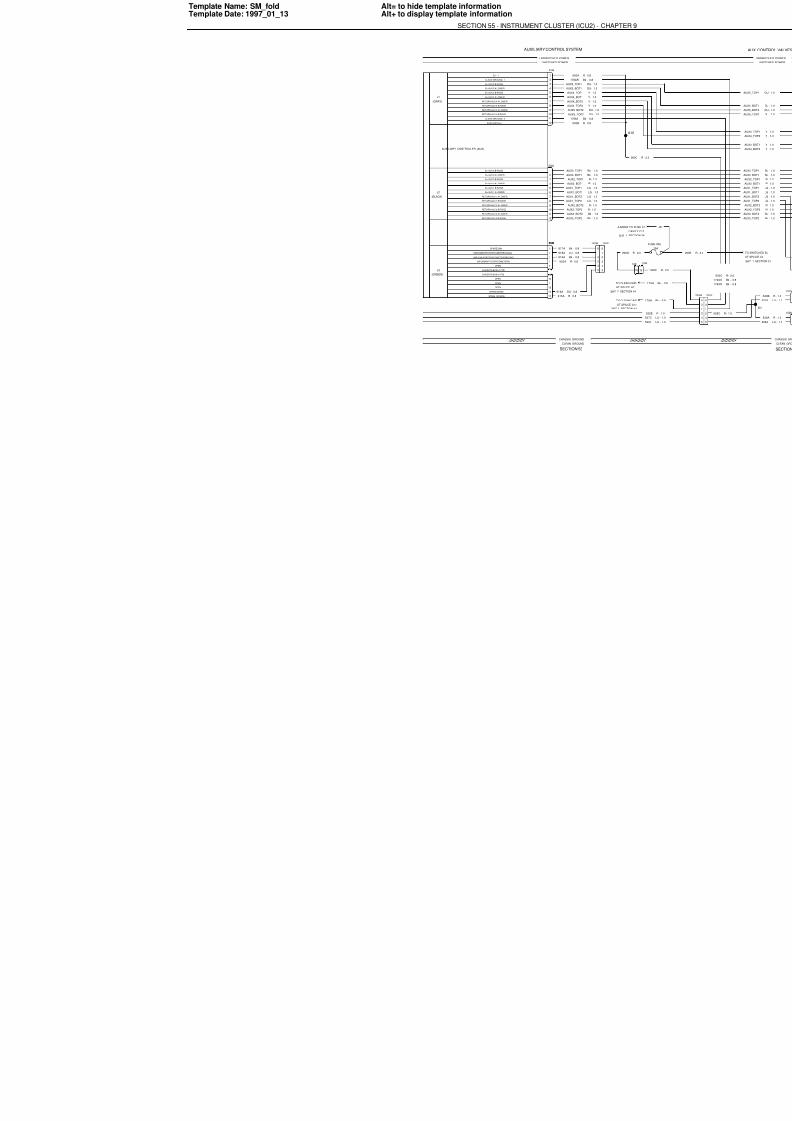
7/23/2019 Case Error Codes
http://slidepdf.com/reader/full/case-error-codes 137/140
Template Name: SM_foldTemplate Date: 1997_01_13
Alt= to hide template informationAlt+ to display template information
SECTION 55 - INSTRUMENT CLUSTER (ICU2) - CHAP
AUXILIARY CONTROLLER (AUX)
(GRAY)
J1
B+ - 1
CLEAN GROUND- 1
B+ AUX 5 B RAISE
B+ AUX 5 A LOWER
B+ AUX 4 B RAISE
B+ AUX 4 A LOWER
RETURN AUX 4 A LOWER
RETURN AUX 4 B RAISE
RETURN AUX 5 A LOWER
RETURN AUX 5 B RAISE
CLEAN GROUND- 2
AUXILIARY B+ 2
B+ AUX 3 B RAISE
B+ AUX 3 A LOWER
B+ AUX 2 B RAISE
B+ AUX 2 A LOWER
B+ AUX 1 B RAISE
B+ AUX 1 A LOWER
RETURN AUX 1 A LOWER
RETURN AUX 1 B RAISE
RETURN AUX 2 A LOWER
RETURN AUX 2 B RAISE
RETURN AUX 3 A LOWER
RETURN AUX 3 B RAISE
SPARE SINK
IMPLEMENT POTENTIOMETER SIGNAL
IMPLEMENT POTENTIOMETER GROUND
IMPLEMENT POTENTIOMETER B+
OPEN
CAN DATA BUS LO (TR)
CAN DATA BUS HI (TR)
OPEN
OPEN
OPEN
SPARE SENSE
SPARE SOURCE
UNSWITCHED POWER
SWITCHED POWER
CHASSIS GROUND
CLEAN GROUND
AUXILIARY CONTROL SYSTEM
SECTION 53
0.8-R
900A
0.8-R
900B
1.0-DU
AUX5_TOP1
1.0-DU
AUX5_BOT1
1.0-Y
AUX4_TOP1
1.0-Y
AUX4_BOT1
1.0-Y
AUX4_BOT2
1.0-Y
AUX4_TOP2
1.0-DU
AUX5_BOT2
1.0-DU
AUX5_TOP2
0.8-Bk
179AR
0.8-Bk
179AS
1
2
3
4
5
6
7
8
9
10
11
12
53M
1
2
3
4
5
6
7
8
9
10
11
12
54M
1
2
3
4
5
55M
8
9
10
11
12
55M
6
1
3
2
4
5
150F
5
4
2
3
1
6
150M
S
JU
2SHT
AT
TO
2SHT
AT
TO
1.0-Bk
AUX3_TOP2
1.0-Bk
AUX3_BOT2
1.0-R
AUX2_TOP2
1.0-R
AUX2_BOT2
1.0-LG
AUX1_TOP2
0.8-DU
916A
0.8-R
915A
0.8-R
920A
0.8-Bk
919A
0.8-LU
918A
0.8-Bk
917A
1.0-LG
AUX1_BOT2
1.0-LG
AUX1_BOT1
1.0-LG
AUX1_TOP1
1.0-R
AUX2_BOT1
1.0-R
AUX2_TOP1
1.0-Bk
AUX3_BOT1
1.0-Bk
AUX3_TOP1
(GREEN)
J3
(BLACK)
J2

7/23/2019 Case Error Codes
http://slidepdf.com/reader/full/case-error-codes 138/140
9-138
PRINTER NOTE:
THIS PAGE IS BLANK
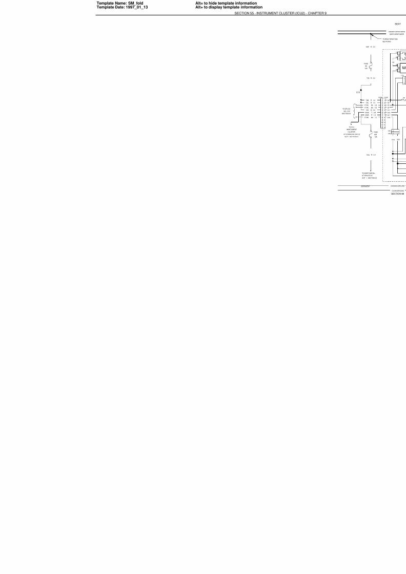
7/23/2019 Case Error Codes
http://slidepdf.com/reader/full/case-error-codes 139/140
Template Name: SM_foldTemplate Date: 1997_01_13
Alt= to hide template informationAlt+ to display template information
SECTION 55 - INSTRUMENT CLUSTER (ICU2) - CHAP

7/23/2019 Case Error Codes
http://slidepdf.com/reader/full/case-error-codes 140/140
PRINTER NOTE:
THIS PAGE IS BLANK