case study of digital control systems for high-voltage substations
TRANSCRIPT

Case Study of Digital Control Systems for High-Voltage Substations
James Propst Western Area Power Administration (WAPA)
Mike Dood Schweitzer Engineering Laboratories, Inc.
Presented at the 5th Annual Clemson University Power Systems Conference
Clemson, South Carolina March 14–17, 2006
Previously presented at the DistribuTECH Conference, February 2006
Originally presented at the 7th Annual Western Power Delivery Automation Conference, May 2005
1
CASE STUDY OF DIGITAL CONTROL SYSTEMS FOR HIGH-VOLTAGE SUBSTATIONS
James Propst Western Area Power Administration (WAPA)
Huron, SD USA
Mike Dood Schweitzer Engineering Laboratories, Inc.
Pullman, WA USA
ABSTRACT This paper describes the design, implementation, and commissioning of a complete protection and control system retrofit project at a large transmission substation. Fort Thompson Substation, located in South Dakota, has two 345/230 kV step-down transformers with two 345 kV lines and twelve 230 kV lines. Western Area Power Administration (Western) undertook a project several years ago to completely renovate all the protection and control systems at this substation. They used the automation practices that Western had developed to reduce costs of new substation construction. While it is easy to cost justify integrating and automating systems when building a new substation, it is traditionally more difficult to justify automation system upgrade schemes when doing a renovation project. However, recent innovations in the integration capabilities of microprocessor-based protective relays, and other substation IEDs, make a complete integration system upgrade, including automation, cost effective compared to selective replacement of individual IEDs, wiring, and testing.
This paper describes the justification and special challenges of automating an existing substation. It also discusses the overall system design concept of the integration and automation schemes that were employed. Topics covered in the paper include:
• Extensive use of fiber-optic cables to replace all control wiring in the yard
• Extensive use of multifunctional protection devices to eliminate wiring and equipment that would be required in a traditional design
• Replacement of hardwired lockout relays with “soft” logic
• Elimination of hardwired I/O to the RTU
• Project management tools used to ensure completion dates and to maintain budget
• Challenges of designing operator interface screens
• Impact on the workforce in migrating to a completely automated substation
• Insights gained in testing and commissioning the substation
INTRODUCTION Western Area Power Administration markets and delivers reliable, cost-based hydroelectric power and related services within a 15-state region of the central and western U.S. and is one of four power marketing administrations within the U.S. Department of Energy whose role it is to market and transmit electricity from multi-use water projects. Western’s transmission system carries electricity from 55 hydropower plants operated by the Bureau of Reclamation, U.S. Army Corps of Engineers, and the International Boundary and Water Commission. Together, these plants have a capacity of 10,600 megawatts.
2
Western started its automation projects with the goal of reducing the construction cost of new substations. Western estimated it could save 40 percent in building size and cost alone. Western also estimated similar savings could be realized in control panel costs with integrated digital controls.
Western began deploying programmable logic controller (PLC) control systems in 1996 with a pilot project at the Fort Thompson 230 kV yard. The pilot substation consisted of four 230 kV lines with a breaker-and-a-half bus arrangement. These initial designs replaced only the substation control wiring—no aspect of protection was included in the project. The PLC designs included an industrial computer running a Wonderware® InTouch software application as the local operator’s monitoring and control system human-machine interface (HMI). After modifications to the original design, the PLC design became the standard and was deployed in 20 substations across Western’s service territory.
Western started looking at alternatives to the PLC design soon after these installations, and in 1998 they attended the open house and demonstration of the Philadelphia Electric Company (PECO) integrated system design. Meter and relay (M&R) mechanics at Western were not comfortable or confident with working on the PLCs and associated ladder logic, but they were comfortable working with microprocessor relays. Western also experienced PLC control failure associated with the use of the protocol interface to SCADA. Western felt that moving control functionality from the PLCs to a microprocessor relay and communications processor would address the reliability and comfort issues that the M&R employees had with PLCs. Eventually, Western chose the highly reliable combination of microprocessor relays and communications processors as their new digital control system (DCS) design to replace the PLC-based platform and chose to make Fort Thompson a pilot project. Once again, as was done with the PLC project years earlier, the pilot substation consisted of four 230 kV lines with a breaker-and-a-half bus arrangement.
In the conversion from the PLC control system to the DCS design, Western also decided to include protective elements, or lockouts, in the DCS design. One lesson learned from the PLC design was that mixing digital and hardwired logic adds complexity to both portions. Because of the design and manufacturing processes, typical MTBF, and environmental ratings of PLCs, Western was not comfortable placing any protective functions in the PLC. Because the DCS would use protective relays for control, it seemed natural to have the lockout function reside there as well. Western chose a single dedicated microprocessor breaker failure relay as the “input” point to the DCS system. The outputs from the DCS system used contacts from the breaker failure relay and one of the line relays to provide a redundant control path for the power circuit breakers. Communications processors were used in the design to provide the interface to SCADA and the local HMI.
Although this initial DCS design was a step in the right direction, it was apparent that an additional iteration in the design would be required to provide enhanced economy and simplicity. The next iteration was the use of fiber-optic cable to replace copper communications and the relocation of the DCS system inputs to be field I/O devices mounted near the station apparatus rather than duplicate the inputs with parallel copper wiring to the centralized IED. Thus, integrated digital communications allowed the I/O of the IEDs to be used for several functions within the DCS. A single 52a contact from the breaker auxiliary stack, wired to a remote I/O device, was used to provide this status for the entire system, including the protective functions. Alarm points were wired only into the I/O device at the equipment, instead of also being separately wired to the control building and connected to an RTU.
3
PROJECT DEFINITION
Fort Thompson 345 kV Yard
Operations determined that the 345/230 kV transformers in the 345 kV yard should be separated from a common bus, creating a four-position ring bus configuration. This work required the addition of a 345 kV breaker and required modifying the bus work. The substation controls and relaying were largely original equipment from the 1960s. Western decided to replace the control panels because extensive wiring changes were needed to bring the substation up to current Western standards for SCADA.
The substation was built on expansive soils, which tend to move considerably, and which caused the foundation for the control building to crack in half. As the two halves settled, a three-inch crack developed in the wall, which had been covered with a steel plate to keep the birds out. These problems made fixing the building impractical, so it was replaced with a modular, energy-efficient, low-maintenance building. The design of a DCS using integrated relays allowed the building to be over 40 percent smaller because integrated systems are much smaller than conventional PLC and RTU control designs.
The expansive soils over the years had created shifting in the control cable trays, causing the covers to have gaps. These gaps allowed rodents to enter the cable tray, causing substantial damage to control cable jackets. Unjacketed cable was eaten bare in many spots. The joint owner of the substation equipment agreed the control cable should also be replaced.

4
Figure 1 Fort Thompson 345 kV yard bus arrangement after Stage 06 modifications were
completed. Four 345 kV circuit breakers, three 13.8 kV reactor breakers, eleven 345 kV MODs, and two 345 kV interrupters are under DCS control.
Fiber-Optic Cable
Fort Thompson, like most 345 kV substations, is a large substation. Cable lengths up to 1000 feet were to be replaced. At the time of this project, 12/C #10 shielded cable cost about $2/foot. Because the project would require about 17,000 feet of 12/C cable, the use of fiber-optic cable was considered as an option. Western determined that they could replace the 17,000 feet of 12/C copper with 2,700 feet of fiber-optic cable. The cost of 24-fiber cable at the time of the project was $1.84/foot. This represented an upfront savings of $29,000, which would be spent on additional hardware requirements for the use of fiber-optic cable. The concept up front was to show fiber was competitive with copper in the substation.
The fiber-optic cable would be installed to each circuit breaker, transformer, and reactor. Motor-operated disconnect (MOD) controls and inputs would be wired over copper cable from the MOD to the associated circuit breaker where a remote I/O device would be installed to accommodate both MODs associated with the circuit breaker. At the transformers, alarms and trips from sudden pressure, winding temperature, and low oil would be connected to the remote I/O device and brought to the control house over fiber. Coupling the MOD and MOI controls with the major equipment would save fiber terminations. Considerable amount of copper cable would be saved

5
because the MODs were close to the circuit breaker, eliminating up to a 1000 feet of 12/C for each MOD from the control house.
The use of fiber-optic cable would allow the digital inputs to be input into the DCS at the equipment. Western estimated that at least 75 percent of the dc wire terminations were eliminated. Consider that a cable must be terminated on each end, in this case to a terminal block in the building, then to a terminal block in the RTU, and finally to the RTU. This would all be replaced with a single switchboard wire at the individual piece of equipment.
About this same time, the logic processor became available on the market. This device allows the digital inputs to be distributed in real time among the relays and provides SOE (sequence-of-event) information for the RTU. The logic processor allowed a single 52a contact from the breaker to be distributed digitally over communications links to the primary relay, secondary relay, breaker failure relay, and the RTU. This further diminished the required wiring terminations.
The logic processor would also be used to create an extended digital protection system that tied all the individual pieces of equipment together to create an extended integrated protection system. Because the logic processor would be used for SOE information, it needed to receive the digital relay operate event. This same piece of information would be sent to the breaker failure relay to initiate breaker failure. The use of the logic processor would eliminate the long block closing strings and breaker failure initiate wiring. All of this hardwired logic would be replaced with EIA-232 cables and settings.
Past Functionality
From the very first pilot project, Western had a high level of information flow with operations personnel, and they provided the manufacturer with feedback on their operational requirements. Redundant controls were established as a requirement, as there was a concern about the ability to respond to and correct equipment failures with the new design. For the same reason, redundant HMI computers with redundant power supplies and hard drives running RAID 1 controllers were used. The new center of the system, the communications processor, had Modbus Plus® protocol available, so Western’s previous HMI design modules, also based on this protocol in the PLC, were used with very little modification.
Good Site
Fort Thompson was deemed a good site for this project, because it was relatively small. A total of 7 breakers and 13 switches would be placed under DCS control. This would require fiber to be installed to 11 pieces of equipment—a very manageable number. The physical size of the yard made the fiber attractive, because a lot of copper cable could be eliminated. And, finally, the project had strong support from Western’s Communications division, which installed and terminated the fiber-optic cable.
THE DCS DESIGN
Controls
Western operations personnel wanted the ability to trip and close a circuit breaker in the event of equipment failure. Therefore, Western designed redundant controls as a standard part of the
6
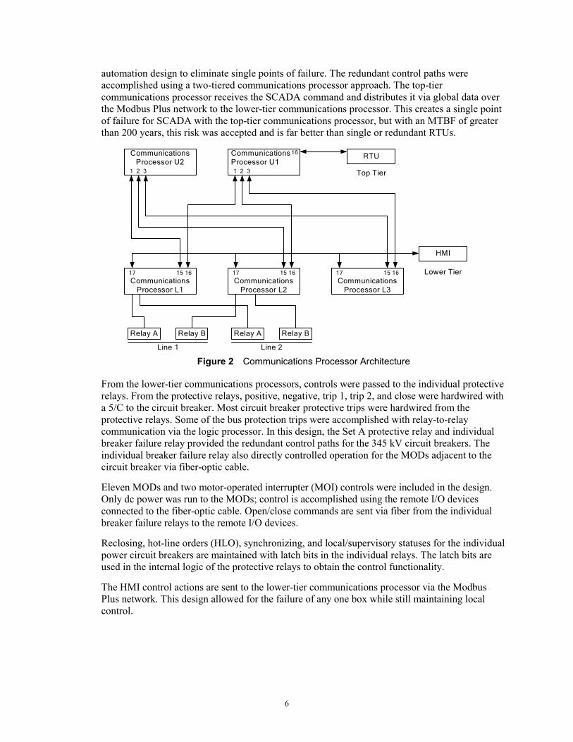
automation design to eliminate single points of failure. The redundant control paths were accomplished using a two-tiered communications processor approach. The top-tier communications processor receives the SCADA command and distributes it via global data over the Modbus Plus network to the lower-tier communications processor. This creates a single point of failure for SCADA with the top-tier communications processor, but with an MTBF of greater than 200 years, this risk was accepted and is far better than single or redundant RTUs.
CommunicationsProcessor U2
1 2 3
CommunicationsProcessor U11 2 3
CommunicationsProcessor L1
15 1617
CommunicationsProcessor L2
15 1617
CommunicationsProcessor L3
15 1617
RTU
HMI
Relay A Relay B Relay A Relay B
16
Line 1 Line 2
Top Tier
Lower Tier
Figure 2 Communications Processor Architecture
From the lower-tier communications processors, controls were passed to the individual protective relays. From the protective relays, positive, negative, trip 1, trip 2, and close were hardwired with a 5/C to the circuit breaker. Most circuit breaker protective trips were hardwired from the protective relays. Some of the bus protection trips were accomplished with relay-to-relay communication via the logic processor. In this design, the Set A protective relay and individual breaker failure relay provided the redundant control paths for the 345 kV circuit breakers. The individual breaker failure relay also directly controlled operation for the MODs adjacent to the circuit breaker via fiber-optic cable.
Eleven MODs and two motor-operated interrupter (MOI) controls were included in the design. Only dc power was run to the MODs; control is accomplished using the remote I/O devices connected to the fiber-optic cable. Open/close commands are sent via fiber from the individual breaker failure relays to the remote I/O devices.
Reclosing, hot-line orders (HLO), synchronizing, and local/supervisory statuses for the individual power circuit breakers are maintained with latch bits in the individual relays. The latch bits are used in the internal logic of the protective relays to obtain the control functionality.
The HMI control actions are sent to the lower-tier communications processor via the Modbus Plus network. This design allowed for the failure of any one box while still maintaining local control.

7
Figure 3 The I/O device on the right provides open and close commands for the MODs. It also provides the 43LR, 52a, and 52b status to the DCS. The I/O device on the left provides inputs into the DCS for the individual power circuit breakers. Note the extra fiber-optic cable, which
allowed terminations to be completed in a mobile van and provided additional cable for when the power circuit breaker is replaced.
Substation Computer
Hardware Design
Western has used Wonderware as the HMI in their digital designs for several years. Due to the very limited knowledge of this software and computers in general in the workforce and the associated concern over the ability to respond to equipment failure, Western chose an industrial PC. Western purchased redundant PCs with hot-swappable redundant power supplies and hot-swappable redundant hard drives. The hard drives use a SCSI RAID 1 controller to mirror the drives. The PCs are rack mounted in the control panel. To provide isolation to transients and to power the PCs, Western installed redundant dc-ac inverters that are normally fed from ac but switch to dc upon loss of ac. The inverters served as a universal power supply, because they switch supply sources without causing any disruption in the PC. A keyboard, video, mouse (KVM) device switches the PCs to a single set of LCD displays, keyboard, and mouse.
HMI Application Design
Western uses a dual display for the HMI. The left screen displays the station one-line with status. They also use the buttons on the left screen to fill in the variables in the right screen template used for PCB control. The buttons rise when the cursor is placed over them. The 43LS, 79, and 85 statuses are shown directly on the screen. The 43LR, 52a, and 52b drive the color of the breaker status. When the 43LR is in the local position in the circuit breaker, the breaker status box is gray, with an M for “Maintenance” indication independent of the breaker position. The circuit breaker closed indication is red—open is green.
8
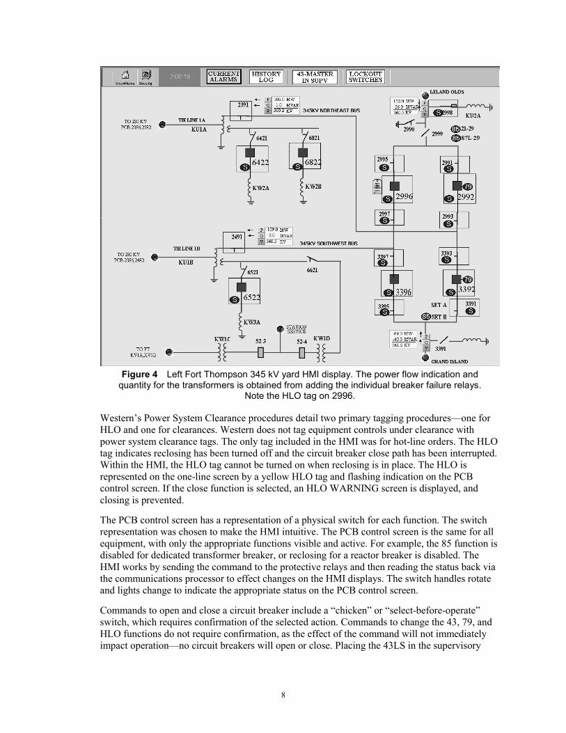
Figure 4 Left Fort Thompson 345 kV yard HMI display. The power flow indication and
quantity for the transformers is obtained from adding the individual breaker failure relays. Note the HLO tag on 2996.
Western’s Power System Clearance procedures detail two primary tagging procedures—one for HLO and one for clearances. Western does not tag equipment controls under clearance with power system clearance tags. The only tag included in the HMI was for hot-line orders. The HLO tag indicates reclosing has been turned off and the circuit breaker close path has been interrupted. Within the HMI, the HLO tag cannot be turned on when reclosing is in place. The HLO is represented on the one-line screen by a yellow HLO tag and flashing indication on the PCB control screen. If the close function is selected, an HLO WARNING screen is displayed, and closing is prevented.
The PCB control screen has a representation of a physical switch for each function. The switch representation was chosen to make the HMI intuitive. The PCB control screen is the same for all equipment, with only the appropriate functions visible and active. For example, the 85 function is disabled for dedicated transformer breaker, or reclosing for a reactor breaker is disabled. The HMI works by sending the command to the protective relays and then reading the status back via the communications processor to effect changes on the HMI displays. The switch handles rotate and lights change to indicate the appropriate status on the PCB control screen.
Commands to open and close a circuit breaker include a “chicken” or “select-before-operate” switch, which requires confirmation of the selected action. Commands to change the 43, 79, and HLO functions do not require confirmation, as the effect of the command will not immediately impact operation—no circuit breakers will open or close. Placing the 43LS in the supervisory

9
position disables all other controls and is represented with a SUPV label displayed over the control switch handle. The update time on the HMI is about two seconds.
Figure 5 Right Fort Thompson PCB Control Screen. The chicken switch is
displayed for confirmation of the control action TRIP PCB2996. Chicken switch confirmation is displayed for trip and close actions.
A small alarm window is displayed on the PCB control screen as well, with the option of displaying all alarms or the selected breaker alarms. This function is easily accomplished with the HMI software’s built-in displays. The metering associated with the circuit breaker is also displayed on the PCB control screen and can be changed to either line in the case of a ring bus or a breaker-and-a-half bus by selecting the desired meter on the left window of Figure 5. Metering quantities are especially easy to display and scale. The metering quantities are obtained from one of the protective relays.
The current alarms or the alarm history can also be displayed on the right window of Figure 5. Alarms are displayed with status; red is active and unacknowledged, yellow is active and acknowledged, and white is reset and unacknowledged. Time, date, description, comment, and group name are displayed. Sort functions are also available. Because Western did not latch their alarms or events, the HMI display can miss fast resetting changes. Modbus Plus protocol does not support the SOE function. Western chose this direction because they have access to their SCADA master and believed active alarms would account for the majority of use after commissioning was completed. During commissioning, Western relied on their SCADA master for events.

10
Figure 6 SCADA log was available for commissioning via Ethernet connection
The HMI interacts with the lower-tier communications processors. If SCADA control is lost, the local platform is still redundant with respect to controls. Metering quantities are obtained only from a single source. Statuses are combined in the HMI. The HLO status is “ANDed” to ensure both reclose paths are turned off and closing is prevented. The 43LS, 85, and reclose paths are “ORed” to allow for relay failure or testing.
Lockouts
With the first DCS design, Western went digital—no switches, which meant a software lockout. Wired logic or digital logic is complicated, but mixing them has a cumulative effect and further complicates each portion. Furthermore, the logic in wiring an output from a relay to trip a lockout and then wiring a contact from the lockout back to the same relay to block closing is circular and confusing. Most tripping functions of the software lockout, such as transformer lockouts, are accomplished with relay outputs. Bus lockouts are generally accomplished via the extended digital protection system by relay-to-logic processor-to-relay communication. This may add 4 ms to the tripping time, but because this function is competing with a Zone 2 trip, which in this case can take up to 20 cycles, it is not an issue.
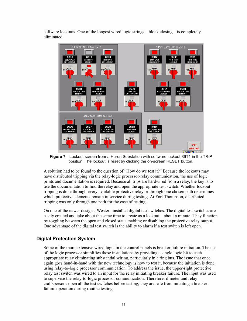
In the DCS design, the lockout function is primarily to block close because the contact multiplication is not necessary. The block close functions are combined in the logic processor to a single bit, which is then sent to the closing relays. The lockout function is maintained until reset by using latch bits that maintain their value through a power cycle. The software lockouts are displayed on the HMI, and the reset function is active when the lockout is in the tripped position. Software lockouts take less than one minute to manually configure in the HMI and even less time to configure in the logic processor. There are huge savings in design and installation costs with
11
software lockouts. One of the longest wired logic strings—block closing—is completely eliminated.
Figure 7 Lockout screen from a Huron Substation with software lockout 86T1 in the TRIP
position. The lockout is reset by clicking the on-screen RESET button.
A solution had to be found to the question of “How do we test it?” Because the lockouts may have distributed tripping via the relay-logic processor-relay communication, the use of logic prints and documentation is required. Because all trips are hardwired from a relay, the key is to use the documentation to find the relay and open the appropriate test switch. Whether lockout tripping is done through every available protective relay or through one chosen path determines which protective elements remain in service during testing. At Fort Thompson, distributed tripping was only through one path for the ease of testing.
On one of the newer designs, Western installed digital test switches. The digital test switches are easily created and take about the same time to create as a lockout—about a minute. They function by toggling between the open and closed state enabling or disabling the protective relay output. One advantage of the digital test switch is the ability to alarm if a test switch is left open.
Digital Protection System
Some of the more extensive wired logic in the control panels is breaker failure initiation. The use of the logic processor simplifies these installations by providing a single logic bit to each appropriate relay eliminating substantial wiring, particularly in a ring bus. The issue that once again goes hand-in-hand with the new technology is how to test it, because the initiation is done using relay-to-logic processor communication. To address the issue, the upper-right protective relay test switch was wired to an input for the relay initiating breaker failure. The input was used to supervise the relay-to-logic processor communication. Therefore, if meter and relay craftspersons open all the test switches before testing, they are safe from initiating a breaker failure operation during routine testing.

12
The use of a single 52a contact essentially saves a 12/C cable. In traditional designs, Western would need a 52a for the primary relay, secondary relay, breaker failure relay, each RTU (Western often has more than one), and a 52b for the sync select circuit. The 52a contact is wired to the remote I/O at the circuit breaker and the status is distributed via the logic processor to each relay and the RTU. The RTU distributes the circuit breaker SOE to each utility. Use of the logic processor, like the protective relays, creates an accurate time stamp of change of state. Therefore, even if complicated communications schemes add communications delays, everything is time stamped relative to the same accuracy. In some cases, data moving through multiple IEDs have been measured to have up to an 8 ms delay in transit. This additional delay is not a concern and may actually improve the accuracy of the 52a timing. Usually, the 52a contacts timed in circuit breakers lead the main contacts. Because the auxiliary switches are mechanical, they must close before the main contacts quit moving. And because Western does not routinely adjust the lead times, a range of 1/4 to as much as one cycle of lead time has been observed in the 52a auxiliary switch. The protective relay needs to see a 52a transition after the trip command to complete the reclose initiation sequence. Some communications paths, even with fiber, can take longer to transmit a POTT signal, used in the reclose supervision, than it takes some of the newer SF6 breakers to operate. The delay in the 52a may actually improve reclosing performance by allowing additional time for the transmission of the POTT signal. The use of the 52a is imprecise in analysis work as well, for the same reasons; additionally, there is always some contact assertion time that must be taken into account.
The SOEs were collected by the RTU from the logic processor. Most of the SOEs were already present in the logic processor after the block close strings and breaker failure initiation functions were incorporated into the logic processor. Relay-to-relay protective functions such as POTT or DTT are echoed to the logic processor. The logic processor also provides all equipment alarms directly to SCADA. Equipment alarms were passed to the HMI via the communications processor. Connecting the remote I/O to the logic processor makes the SCADA update time totally dependent on the RTU and the SCADA master, as the logic processor updates information in relay time—every 1/4 cycle.
RTU
Analog quantities are obtained from the protective relays by the lower-tier communications processors, scaled, and sent to the upper-tier communications processor, where they are mapped for DNP. Statuses follow the same path but are combined as appropriate in the upper tier. The 43LS and Reclose functions are “ORed” and the HLO statuses are “ANDed” in the upper tier. Update time for this process is approximately two seconds, to the point where the data are read by SCADA.
No I/O boards were used with the RTU. Nonoperational data such as “personnel on site” were wired to the auxiliary inputs on the communications processors and logic processors. Control for items such as the yard lights was accomplished with the auxiliary outputs on the communications processors and logic processors as well. The elimination of RTU direct I/O changes the function of the RTU to a multiport protocol converter. It also represents a significant savings in hardware and labor costs. An RTU for this size of facility would easily cost $20,000 with the peripheral boards. Future designs will eliminate the need for the RTU altogether.
Fiber
As was previously mentioned, part of this project included replacing the copper control cable that had been damaged by rodents. Both technical and cost considerations were taken into account in

13
the decision to replace the copper control cables with fiber-optic cables. Because this project is using communications-dependent schemes for not only monitoring and control but also for protective applications, the reliability and security of the intrasubstation communications have become much more critical aspects of the design.
The electrical substation environment in the upper Midwest includes many environmental challenges to reliable and secure communications. These challenges include high-current faults, temperature extremes, high voltages, electromagnetic interference, and electrostatic discharge. To overcome these communications challenges and to provide economical, reliable, secure, and safe communications, Western chose to use fiber-optic cable to interconnect monitoring and control systems. Fiber-optic cable is ideal for the harsh electrical environment of the substation. In addition, fiber-optic transceivers that required no external power source or external mounting were used. They simply plug into the serial port and are powered from the communications control lines. These transceivers are designed to work dependably in the harsh substation environment, just like the equipment to which they are connected.
Because of the physical arrangement, there are two 345 kV breakers and one reactor with an MOI in each of the two bays of the ring bus. Western ran one pair of fibers to each 345 kV breaker for the breaker 43LR, 52a, 52b, and alarms; another pair of fiber for the MOD 43LR, 52a, 52b and open/close functions for each of the MODs associated with each breaker; and another pair for future use. This required a 6-fiber cable to each piece of equipment. Because each bay required 18 fibers, a 24-fiber cable was run to a central point in the bay, where the three 6-fiber cables were connected to it and placed in a ground-level vault. All fiber-optic cables were installed in conduit with fabric interduct. The conduit was directly buried adjacent to the cable tray. The fiber-optic conduit has a large coefficient of expansion and is difficult to manage in the cable trays because of heat fluctuations. Fiber-optic cable with the heavy PVC jacket was chosen for structural integrity.
On each piece of equipment, a 2’ x 3’ x 1’ deep enclosure box with a gasket door was mounted. The fiber termination box, fiber storage trays, and remote I/O were mounted in this enclosure. Switchboard wire was used for connecting the I/O to the equipment. A 5/C cable was installed from each MOD to the circuit breaker. This saved up to 1000 feet of 12/C for each MOD, as wires were doubled to compensate for voltage drop.
In the control building, the fiber was terminated in storage racks in the control panels. This location made the patch cables easy to install.
During the design process, several recently completed traditional facilities were reviewed. It was interesting, as every circuit breaker had enough alarms combined to limit the total alarms for each breaker to five. This was due to normally installing two 12/C cables to each breaker. Multimode fiber was chosen, as the terminal equipment is less expensive. The 24-fiber cable cost 1.84/foot or about $.15/foot/pair. The 6-fiber cable cost was slightly higher per pair at $.16. So a 1000-foot installation had a material cost of $160, the remote I/O was $375, the enclosure with termination rack was $200 ($800 split four ways as the equivalent of four 12/C cables were eliminated—two for the breaker and one for each MOD), and a fiber-optic transceiver was $362, for a total of $1087. With 12/C #10 cables costing about $2/foot, the material cost for copper is $2,000 for each cable. The labor is difficult to compare between the two methods, but 1000 feet of 12/C cable cannot be pulled by one person, and it takes time to dress out and terminate the four cable ends. Additionally, no further wiring is required in the building using fiber. Because the communications personnel were not wiring an RTU, they had time to fuse the fiber, and the climate-controlled environment was a nice place to work on a hot summer day.
14
To provide control for the circuit breakers, a 5/C cable was installed. The wires were assigned to positive, negative, trip1, trip2, and close. Therefore, one fiber pair and one 5/C cable replaced two 12/C cables. To provide control for the MODs associated with the circuit breaker, a pair of fiber replaced two 12/C cables. The materials cost for all copper would have been about $8000 for the four 1000-foot lengths for the circuit breaker and MODs. The fiber/copper combination material cost was less than half that amount at about $3,200 dollars. Not only was the fiber less costly, but an infrastructure was also installed for a future Reliability Centered Maintenance (RCM) program or possible digital current and voltage signals.
Ethernet
Western installed an Ethernet network in the control building, with connections on the control panels. The Ethernet connection was used to access the SCADA master, which was used extensively during commissioning and checkout. The communications processor and HMI were connected to the network as well. Access via Western’s intranet was deemed more secure than dialup. These connections allow for remote access into any of the substation IEDs to retrieve event reports. An automated scheme to retrieve these event reports is currently being evaluated. The HMI connection allows for virus-checking software updates and remote hard-drive maintenance. The client software for the RAID controller allows hard drives to be rebuilt remotely if they stop because of an error.
Connection to the Internet during commissioning made file sharing with experts and the manufacturer’s technical staff extremely easy.
Documentation
With the new technology, new ways to document the functionality were required. Traditional ladder logic diagrams for schematics were replaced with logic diagrams as the breaker schematics became two trip contacts and two close contacts. Relay schematics became little more than wiring diagrams because the only wired inputs were trip-coil monitors and relay-to-relay communication disable; wired outputs were trip, close, and alarm.
Spreadsheets were used to track information like RTU and HMI points, tag names, DNP index, and relay element names. Tables were included on schematics to track internal protective relay element usage and function.
LESSONS LEARNED
Training
Craftspersons responsible to keep a site functioning often want to know only about the specific features being used in a system—not every function a particular piece of hardware can perform. Therefore, Western worked with the vendor in developing a target training course on the communications processors and logic processors. This training was well received, and it was followed by questions such as “Yes, but how does it get from here to there?” and “How do I fix it?” At this point, Western internally developed a three-day block of 101-type training on the functional blocks of the DCS design, how they integrate, and basic troubleshooting.
The internal training was conducted for all meter and relay personnel. Other attendees were individuals from operations, management, and engineering with an interest in DCS. The goal of

15
the training was to present an overview of the DCS system and how each function was accomplished by the components of the system. The type of information needed to troubleshoot the system was presented. Segments included alarms, SOE, control, HMI, DCS control, analogs, Fiber 101, and Ethernet 101.
While basic training is essential, there is no substitute for actually working with the equipment. The classroom training is a required prerequisite, but the final part of the learning occurs during the installation, commissioning, and final checkout. Training also requires sitting down with the new primary tool—the PC, learning to work with it and developing a new set of analytical tools for the PC.
DCS Design
The architecture chosen for the first project remains unchanged in the Upper Great Plains region. While there have been advances and changes within the individual pieces, the overall functionality is the same. For example, control interface protocol from the RTU to the communications processor has changed from Modbus to DNP, but from that point through the system, it works the same way from the first substation to the tenth substation. The Upper Great Plains region of Western has installed a DCS control system in 11 substations.
Initially, one team at Western was working with DCS designs, so a standard was not an issue. As the design spread to new projects and other regions of Western starting work on their facilities, a difference in standards developed across Western. Western is in the process of addressing these differences and working toward a common solution. Western experienced some poor results when standards were adopted and implemented without testing and verifying the design. One recent example was the implementation of a fully redundant system with redundant control, redundant SOE, redundant analogs, and redundant status. This approach proved to be very complicated and introduced decision-making logic because SCADA wants only one set of data. It should be noted that the complexity more than doubles each time a redundant data or control source is added; complexity grows exponentially.
Maintenance
The only failure at Fort Thompson was a remote I/O device. An untrained electrician replaced the remote I/O device during normal work hours. The failure was that an input stayed asserted on the I/O device without the input voltage present.
There have been some settings errors related to reclosing and similar functions. These types of errors were not related to the DCS implementation. There have been no problems with the DCS equipment. Routine maintenance consists of cleaning the air filters for the HMI PCs, file cleanup, and periodically verifying hard drive integrity.
Western is changing the way they label some of the DCS alarms in order to give more descriptive information to the operators. An alarm of “21-3A communication failure” does not mean much to our operations personnel. If that alarm is labeled as “GI Line Loss of Primary Control and Status,” it has immediate meaning for operations.
CONCLUSIONS In order to make the best use of the available features within the protective relays and also to leverage the knowledge that the Western personnel already had with the relays, the control and
16
monitoring functions are now performed by the relays and communications processors. This monitoring and control had previously been performed by less-reliable PLCs and RTUs. The microprocessor relays are now responsible for tripping and closing either via local or via remote operators, or via automation logic settings. The relays are also used wherever practical to bring back status and analog operational and maintenance data from substation apparatus. This eliminated many discrete components such as switches and auxiliary relays, and the associated wiring. Fewer components dramatically increased the quality and reliability of the logic processes by moving them into highly reliable IEDs designed for use in mission-critical applications.
The need to replace all the damaged copper cable in the substation provided the opportunity to evaluate installing fiber. The analysis proved that fiber is an economical solution and provided all the many benefits of using fiber instead of discrete pairs of copper control conductors for each control and monitoring function. Innovative features in the specific products chosen also provide constant monitoring and immediate alarm and notification if the cables to the field I/O are damaged. This is not available via traditional copper cable methods.
The use of multifunctional microprocessor relays resulted in a large reduction in the amount of space required in the control house. This translates into a cost savings during installation, reduced maintenance cost and effort, and higher reliability, because the design uses fewer devices, components, and wires.
The new system provides much more measured and calculated information about the power system for use by operating, maintenance, and engineering personnel than was previously available. Western makes good use of these data in part due to the fact that it is easily accessed through a common user interface. In addition to the power system data, the microprocessor relays provide a wealth of self-test and real-time diagnostic information that makes it easy for operating and engineering personnel to troubleshoot system events. Using these data, Western personnel ensure that schemes and settings are correct.
While the DCS system essentially paid for itself in direct savings, it also creates an infrastructure for new and emerging technologies such as RCM. The IEDs connected via fiber to Western’s intranet have the capability to provide more information than they currently use. As the industry learns how to use this information, Western is poised to easily take advantage of new technology.
Finally, the familiarity with computers and the proliferation of available software packages has made them a logical consideration for the substation. Until recently, applications had to be chosen carefully because both desktop and industrial computers exhibit very low MTBF, or mean time between failures. MTBF is a measure of the relative reliability of a device and is used to choose between devices during design and selection. Features such as redundant power supplies and easily exchanged hard drives make computers marginally more reliable but also obviously increase the required amount of maintenance. Western offset this low MTBF by installing redundant HMIs with redundant hard drives and redundant power supplies. The advent of a new class of more robust devices, rugged computers, will improve individual computer reliability and will eliminate the need for a redundant computer system.
BIOGRAPHIES James Propst received his B.S. degree in Electrical Engineering from South Dakota State University in 1982. He has held several positions in his career at Western Area Power Administration (WAPA) since he joined the organization in 1983, and he has been involved in all aspects of project design, construction, and commissioning. His previous position was in the
17
Meter and Relay Division of the South Dakota Maintenance Office located in Huron, South Dakota. In this position, he was one of the leaders in applying modern technologies to substation controls for high-voltage electrical equipment by hosting three different pilot programs related to integration. James is currently an Electrical Engineer in the Maintenance Engineering Office of the Upper Great Plains Region. His current duties include assisting and training Upper Great Plains region personnel with substation integration, cyber security, standards, and power system disturbance analysis.
Michael J. Dood earned his B.S. in Electrical Engineering from Michigan Technological University in 1979. In 1979, he was employed by Wisconsin Electric Power Company (WEPCo), where he was a Senior Engineer in the Distribution Automation Group. At Wisconsin Electric, his responsibilities included substation automation design and implementation, distribution automation, and SCADA. He also has over 15 years of experience in substation design and project management. In June 1998, he took a position at Schweitzer Engineering Laboratories, Inc. (SEL) as an Integration Application Engineer. His responsibilities include training and assisting SEL customers in their substation integration and automation efforts. Mr. Dood is a registered professional engineer in the state of Wisconsin. He is a senior member of the IEEE and is an active member of the PES Substation Committee.
© 2005 by Western Area Power Administration and Schweitzer Engineering Laboratories, Inc. All rights reserved.
20050407 • TP6197-01