cast steel steam valves - global supply line
TRANSCRIPT

www.australianpipelinevalve.com.au
CAST STEEL STEAM VALVES
API 622 2011 2nd EditionFugitive Emission Certi� ed
SHORT VERSION
Click here for complete version of this catalogue

QUALITY VALVE MANUFACTURER
QUALITY COMMITMENT
Quality is Our First Priority.
Consistent product quality and a proven
track record makes Australian Pipeline
Valve a dependable choice where total
reliability is the number one concern.
Since its founding, APV’s philosophy has
been focused on quality. Our valves
are manufactured in full compliance
to worldwide standards (such as
ASME/ANSI, API, EN, ISO, BS, AS).
70-78 Stanbel Road Salisbury Plain South Australia 5109 Telephone +61 (0)8 8285 0033 Fax +61 (0)8 8285 0044
email: [email protected]
www.australianpipelinevalve.com.au

Figure Number System 4~5*
Physical & Chemical Properties 6*
Gate Valve - Parallel Slide - Class 150-2500 7~15*
Blowdown Valve - Parallel Slide 16~17
Gate Valve - Parallel Slide - Class 150-2500 - Cast Steel 18~19*
Gate Valve - Geothermal Trim 20~21
Globe Valve - Stop Check - Class 150-600 22~23*
Globe Valve - Cast Steel 24*
Globe Valve - Y Pattern Inclined Bonnet Stop Check - Class 150-600 25~26*
Globe Valve - Right Angle - Class 150-600 27~28*
Combination Y Globe/Stop/Check/Strainer 29*
Y Type Stop Check Valve Screwed Ends 30*
Globe Valve - Piston Type - PG01-PG02 31~32
Non Return Piston Check - Lift Type - Class 150-600 33~35*
Globe Valve - Bellow Sealed - Bolted Bonnet 36
Gate Valve - Bellow Sealed - Bolted Bonnet 37
Steam Jacketed Ball Valve Wafer Style 38*
CONTENTS - SHORT VERSION*
© Copyright Australian Pipeline Valve 1990 - 2021 Edition
AUSTRAL IAN P I P E L I N E VA LVE 3
Catalogues, photos, brochures and technical publications are the exclusive property of Australian Pipeline Valve.Any unauthorised reproduction in total or in part, shall result in prosecution. Products and data sheets in this publication are subjectto change at anytime without notice. Australian Pipeline Valve reserves the right to carry out amendments to products and materials.
* This version excludes some of these pages, refer to full version at website.

PAGE 4*For API600 weights see page 41, 42.For Buttweld dimensions and weights see overview brochure. For RTJ dimensions see overview brochure.For 16” to 30” see overview brochure.
ST EAMCO - Ca s t S teel S team Va lves7
STANDARDS COMPLIANCEBasic Design API 600, ANSI B16.34, BS 5157Face to Face Dimension ANSI B16.10End to End Dimension ANSI B16.10Flanged Ends ANSI 16.5B.W. Ends ANSI B16.25Drilling to ANSI or BS/AS 2129 Table D to H or AS 4087 / AS 4331 / ISO 7005-1 PN 10 to 250 Pressure/Temperature Ratings to ANSI B16.5
For installation in applications such as industrial, mining and mechanical services. Suitable for super-heated steam, H.T.H.W steam condensate and water.
This design consists of two discs, kept in contact with parallel body seats, using the line pressure and seating action to effect tight closure.
Temperature changes in the line are accommodated by the expanding disc & do not affect the action of the valve. When being opened or closed, the discs slide across the seat faces, dislodging any foreign matter. The valve operating stem is outside screw rising through the handwheel.
These valves are suitable for full bore steam use, where a low pressure drop across the valve is required.
Also suitable for water, oil, gas, etc.
PRESSURE/TEMPERATURE WCB BODY
For superheated steam etc. consult chart. WC6 chrome-moly available body for high temperature applications.
Class Cat No.
Test Pressure to API 598 (PSIG) Working Pressure
Shell (Hydro)
Seat(Hydro)
Seat(Air)
CWPWOG
Saturated Steam(at 260°C)*
150(AS/BST D to F)
150-P316SXU-S 450 315 80 280 170
300(AS/BST H to J)
300-P316SXU-S 1125 815 80 720 600
600 600-P316SXU-S 2225 1628 80 1440 1200
900 900-P316SXU-S 3350 2442 80 2190 1800
STANDARD MATERIAL SPECIFICATIONSPart Material
1 Body ASTM A216 WCB2 Seat ASTM A105+ST#63 Spring Inconel X-7504 Disc Support Guide ASTM A1055 Disc ASTM A105+ST#66 Stem (1) ASTM A182 F6A7 Bolt ASTM A193 B78 Nut ASTM A194 2H9 Gasket Spiral Wound SS316 + Graphite10 Bonnet ASTM A216 WCB11 Back Seat ASTM A274 410SS12 Packing (2) Flexible Graphite
12A Packing (2) Braided Graphite13 Spacer Ring ASTM A276 410SS14 Gland ASTM A276 410SS15 Yoke Flange ASTM A276 WCB16 Nut ASTM A194 2H17 Bolt ASTM A193 B718 Pin AISI 102019 Yoke ASTM A216 WCB20 Grease Nipple SS30421 Stem Nut ASTM A439 D222 Gland Nut AISI 103523 Handwheel Malleable Iron24 Locking Nut AISI 1035
(1) Stem smoothness Ra ≤ 0.80 µm(2) Stuffing box smoothness Ra ≤ 3.2 µm (superior to API 600)
PARALLEL SLIDE GATE VALVE
PARALLEL SLIDE GATE VALVECAT P316S CLASS 150-900
O.S. & Y. Rising Stem Full Port, Expanded Parallel Slide Gate Valve, Double Disc, Pressure Seal or Bolted Bonnet, Welded-in or Threaded Seat Rings. Mechanically loaded seating for low and high pressure sealing.
Parallel slide dual loaded discs ensure superior shut off and allow by-pass/bleed fitment (double block and bleed requires soft seat inserts).
Pressure/temperature charts available on request.
53
Buttweld ends
18
1
3
4
5
2
22
19
21
20
23
24
8
6
7
13
1716
9
12
11
10
15
14
12a
B
C
A

ST EAMCO - Ca s t S teel S team Va lves 8
SeatingCode
Body SeatSurface Part
No. 3
Double DiscSurface Part
No. 4
StemPart No. 5
Back Seat(Stuffing Box)Part No. 10
X F6 F6 F6 F6
U Stellite Stellite F6 F6
XU Stellite F6 F6 F6
P* F304 F304 F304 F304
R* F316 F316 F316 F316
M* Monel Monel Monel Monel
N* Alloy 20 Alloy 20 Alloy 20 Alloy 20
H* Hastelloy B Hastelloy B Hastelloy B Hastelloy B
VALVE SIZE(NPS)
inch 2 2-1/2 3 4 5 6 8 10 12 14 16 18 20 24
mm 50 65 80 100 125 150 200 250 300 350 400 450 500 600
CLASS150
(Table D to F)
D mm 51 64 76 102 125 152 203 254 305 337 387 438 489 591
A mm 178 190 203 229 254 267 292 330 356 381 406 432 457 508
B (Open) mm 409 472 490 612 720 806 990 1186 1415 1583 1771 1955 2210 2698
C mm 200 200 250 250 350 350 350 450 500 560 640 720 800 900
Weight (kg) RF 20 25 38 55 75 85 134 198 320 400 524 690 900 1350
CLASS300
(Table F to H)
D mm 51 64 76 102 125 152 203 254 305 337 387 438 489 591
A-A1 mm 216 241 283 305 354 403 419 457 502 760 838 914 991 1143
B (Open) mm 428 477 543 650 720 850 1037 1276 1438 1585 1960 2155 2350 2720
C mm 200 250 250 300 300 350 450 500 560 640 720 800 900 1118
Weight (kg) RF 25 44 50 74 124 137 217 337 580 715 1050 1235 1655 2320
CLASS600
D mm 51 64 76 102 125 152 203 254 305 337 387 438 489
A-A1 mm 292 330 356 432 508 559 660 787 838 889 991 1092 1192
B (Open) mm 474 553 593 654 857 970 1122 1330 1519 1716 2110 2400 2461
C mm 250 250 300 350 400 500 560 720 720 720 900 1000 1000
Weight (kg) RF 50 60 85 135 260 345 515 845 1120 1360 1910 2335 2700
CLASS900
D mm 51 60 76 102 120 152 203 254 305 324 375 438
A-A1 mm 372 419 384 460 559 613 740 841 968 1039 1140 1219
B (Open) mm 590 702 740 870 1051 1078 1318 1581 1867 2004 2178 2526
C mm 250 300 300 350 450 560 640 800 800 900 900 900
Weight (kg) RF 110 140 150 220 355 460 800 1050 1600 2220 3000 3870
OVERALL DIMENSIONS (MM) & WEIGHT (KG)
TRIM MATERIAL CODES (TO API 600)
* Add XU modifi er to end of model suffi x if stellite seat, if stellite seat & disc add U modifi er to end.
Note: 15mm to 40mm NB 150 ~ 2500 Class also available refer to individual drawings.
Body Material Codes
None A216 WCB
0 Special
5 A217 C5
6 A217 WC6
7 A217 WC9
8 A351 CF8
8M A351 CF8M
PARALLEL SLIDE GATE VALVE
PARALLEL SLIDE GATE VALVE
CAT P316S CLASS 150-900

PART NUMBER SYSTEMPAGE 4*For API600 weights see page 41, 42.For Buttweld dimensions and weights see overview brochure. For RTJ dimensions see overview brochure.For 16” to 30” see overview brochure.
ST EAMCO - Ca s t S teel S team Va lves11
CAT P316K CLASS 150-1500
Class Cat No.
Test Pressure to API 598 (PSIG) Working Pressure
Shell (Hydro)
Seat(Hydro)
Seat(Air)
CWPWOG
Saturated Steam(at 260°C)*
150(AS/BST D to F)
AP47XUKS 450 315 80 280 170
300(AS/BST H to J)
AP33XUKS 1125 815 80 720 600
600 AP76XUKS 2225 1628 80 1440 1200
900 AP83XUKS 3350 2442 80 2190 1800
1500 AP83XUKS 5626 4078 80 3600 3000
PRESSURE/TEMPERATURE WCB BODY
For superheated steam etc. consult chart. WC6 chrome-moly available body for high temperature applications.
STANDARD MATERIAL SPECIFICATIONSPart Material
1 Body ASTM A217 WCB
2 Seat Ring ASTM A105+STL.6
3 Wedge Blocks ASTM A743 CA40
4 Discs ASTM A105+STL.12
5 Springs Inconel X-750
6 Disc Yoke ASTM A743 C40
7 Guides C.S.
8 Stem ASTM A182 F6A
9 Studs ASTM A193 B7
10 Nuts ASTM A194 2H
11 Gasket 304SS+GRAPHITE
12 Bonnet ASTM A216 WCB
13 Back Seat ASTM A276 410
14 Packing FLEXIBLE GRAPHITE
15 Packing 316+BRAIDED GRAPHITE
16 Gland ASTM A276 410
17 Gland Flange ASTM A217 WCB
18 Pins AISI 1035
19 Eyebolts ASTM A193 B7
20 Nuts ASTM A194 2H
21 Stem Nut ALUMINIUM BRONZE
22 Retaining Nut AISI 1035
23 Handwheel MALLEABLE IRON
24 Nuts AISI 1035
25 Nameplate 316SS
26 Rivets 316SS
27 Bearings SUB-ASSEMBLY
28 Yoke ASTM A216 WCB
29 Studs ASTM A193 B7
30 Nuts ASTM A194 2H
31 Grease Nipple BRASS
* Also available with expanding wedge energiser (no spring) style - refer to drawing.
Buttweld ends
FEATURESExpanding style parallel slide gate valve suitable for super-heated steam, H.T.H.W steam condensate and water.
Temperature changes in the line are accommodated by the expanding disc and do not affect the action of the valve. When being opened or closed, the discs slide across the seat faces, dislodging any foreign matter. These valves are suitable for full bore steam use, where a low pressure drop across the valve is required. Also suitable for water, oil, gas, etc.
O.S. & Y. Rising Stem Full Port, Expanded Parallel Slide Gate Valve, Double Disc, Pressure Seal or Bolted Bonnet, Welded-in or Threaded Seat Rings. Mechanically loaded seating for low and high pressure sealing.
Parallel slide dual loaded discs ensure superior shut off and allow by-pass/bleed fitment (double block and bleed requires soft seat inserts).
Pressure/temperature charts available on request.
PARALLEL SLIDE GATE VALVES - CAST STEEL
PARALLEL SLIDE GATE VALVE (EXPANDING)
A
B
C
1
2
3
4
5
6
7
8
910
11
12
13
1415
16
17
181920
21
22
23
24
25 26
31
31
27
28
29 30
4 433 55 6
A

ST EAMCO - Ca s t S teel S team Va lves 12
SeatingCode
Body SeatSurface Part
No. 3
Double DiscSurface Part
No. 4
StemPart No. 5
Back Seat(Stuffing Box)Part No. 10
X F6 F6 F6 F6
U Stellite Stellite F6 F6
XU Stellite F6 F6 F6
P* F304 F304 F304 F304
R* F316 F316 F316 F316
M* Monel Monel Monel Monel
N* Alloy 20 Alloy 20 Alloy 20 Alloy 20
H* Hastelloy B Hastelloy B Hastelloy B Hastelloy B
TRIM MATERIAL CODES (TO API 600)
VALVE SIZE(NPS)
inch 2 2-1/2 3 4 5 6 8 10 12 14 16 18 20 24
mm 50 65 80 100 125 150 200 250 300 350 400 450 500 600
CLASS150
(Table D to F)
D mm 51 64 76 102 125 152 203 254 305 337 387 438 489 591
A mm 178 190 203 229 254 267 292 330 356 381 406 432 457 508
B (Open) mm 409 472 490 612 720 806 990 1186 1415 1583 1771 1955 2210 2698
C mm 200 200 250 250 350 350 350 450 500 560 640 720 800 900
Weight (kg) RF 20 25 38 55 75 85 134 198 320 400 524 690 900 1350
CLASS300
(Table F to H)
D mm 51 64 76 102 125 152 203 254 305 337 387 438 489 591
A-A1 mm 216 241 283 305 354 403 419 457 502 760 838 914 991 1143
B (Open) mm 428 477 543 650 720 850 1037 1276 1438 1585 1960 2155 2350 2720
C mm 200 250 250 300 300 350 450 500 560 640 720 800 900 1118
Weight (kg) RF 25 44 50 74 124 137 217 337 580 715 1050 1235 1655 2320
CLASS600
D mm 51 64 76 102 125 152 203 254 305 337 387 438 489
A-A1 mm 292 330 356 432 508 559 660 787 838 889 991 1092 1192
B (Open) mm 474 553 593 654 857 970 1122 1330 1519 1716 2110 2400 2461
C mm 250 250 300 350 400 500 560 720 720 720 900 1000 1000
Weight (kg) RF 50 60 85 135 260 345 515 845 1120 1360 1910 2335 2700
CLASS900
D mm 51 60 76 102 120 152 203 254 305 324 375 438
A-A1 mm 372 419 384 460 559 613 740 841 968 1039 1140 1219
B (Open) mm 590 702 740 870 1051 1078 1318 1581 1867 2004 2178 2526
C mm 250 300 300 350 450 560 640 800 800 900 900 900
Weight (kg) RF 110 140 150 220 355 460 800 1050 1600 2220 3000 3870
OVERALL DIMENSIONS (MM) & WEIGHT (KG)
Note: 15mm to 40mm NB 150 ~ 2500 Class also available refer to individual drawings.
PARALLEL SLIDE GATE VALVES - CAST STEEL
* Add XU modifier to end of model suffix if stellite seat, if stellite seat & disc add U modifier to end.
Open Closed
SPECIFICATIONSBasic Design API 600, ANSI B16.34Face to Face Dimension ANSI B16.10End to End Dimension ANSI B16.10Flanged Ends ANSI 16.5B.W. Ends ANSI B16.25Drilling to ANSI or BS/AS 2129 Table D to H or AS 4087 / AS 4331.1 / ISO 7005-1 PN 10 to 250Pressure/Temperature ratings to ANSI B16.5
CAT P316K CLASS 150-1500
PARALLEL SLIDE GATE VALVE (EXPANDING)

*For API600 weights see page 41, 42.For Buttweld dimensions and weights see overview brochure. For RTJ dimensions see overview brochure.For 16” to 30” see overview brochure.
ST EAMCO - Ca s t S teel S team Va lves14
Part Name Carbon Steel to ASTM Alloy Steel to ASTM Stainless Steel to ASTM1 Body A216 WCB A352 LCB A352 LCC A217 WC6 A217 C5 A105 A351 CF8 A351 CF8M A890 4A2 Bonnet A105 A350 LF2 A350 LF2 A105 A105 A182 F316 A182 F304 A182 F316 A182 F513 Gate* A182 F316 A182 F316 A182 F316 A182 F316 A182 F316 A182 F316 A182 F316 A182 F316 A182 F514 Gate Retainer A182 F316 A182 F316 A182 F316 A182 F316 A182 F316 A182 F316 A182 F316 A182 F316 A182 F515 Seat* A182 F316 A182 F316 A182 F316 A182 F316 A182 F316 A182 F316 A182 F316 A182 F316 A182 F516 Stem A564 S174007 Silver Plated-Gasket A182 F316 A182 F316 A182 F316 A182 F316 A182 F316 A182 F316 A182 F316 A182 F316 A182 F518 Thrust Ring A182 F316 A182 F316 A182 F316 A182 F316 A182 F316 A182 F316 A182 F316 A182 F316 A182 F519 Pressure Collar A105 +ENP A350 LF2 +ENP A350 LF2 +ENP A105 +ENP A105 +ENP A105 +ENP A182 F304 A182 F316 A182 F5110 Pressure Plate A105 +ENP A350 LF2 +ENP A350 LF2 +ENP A105 +ENP A105 +ENP A105 +ENP A182 F304 A182 F316 A182 F5111 Gland A182 F316 A182 F316 A182 F316 A182 F316 A182 F316 A182 F316 A182 F304 A182 F316 A182 F5112 Gland Flange A216 WCB A352 LCB A352 LCC A217 WC6 A217 C5 A217 C12 A351 CF8 A351 CF8M A890 4A15 Stop Plate A182 F316 A182 F316 A182 F316 A182 F316 A182 F316 A182 F316 A182 F316 A182 F316 A182 F5116 Gland Adaptor Plate A105 A350 LF2 A350 LF2 A105 A105 A105 A182 F304 A182 F316 A182 F5117 Stem Nut B150 C6190018 Gear Steel19 Dust Proof Cover Steel20 Yoke Steel23 Belleville Spring Steel +ZP/Inconel24 Spring Steel26 Pin A182 F316 A182 F316 A182 F316 A182 F316 A182 F316 A182 F316 A182 F316 A182 F316 A182 F5127 Packing Graphite28 Nut A194 2H A194 7 A194 7 A194 4 A194 4 A193 B16 A194 8 A194 8M A194 8MLCuNa29 Bolt A193 B7 A320 L7 A320 L7 A193 B16 A193 B16 A194 4 193 B8 193 B8M A193 B8MLCuN30 Nut A194 2H A194 7 A194 7 A194 4 A194 4 A193 B16 A194 8 A194 8M A194 8MLCuNa31 Spring Washer Steel32 Bolt A193 B7 A320 L7 A320 L7 A193 B16 A193 B16 A194 4 A193 B8 A193 B8M A193 B8MLCuN33 Nut A194 2H A194 7 A194 7 A194 4 A194 4 A193 B16 A194 8 A194 8M A194 8MLCuNa34 Bolt A193 B7 A320 L7 A320 L7 A193 B16 A193 B16 A194 4 A193 B8 A193 B8M A193 B8MLCuN35 Nut A194 2H A194 7 A194 7 A194 4 A194 4 A194 4 A194 8 A194 8M A194 8MLCuNa37 Stem Indicator Steel38 Packing Ring B150 C6190039 Backseat Hard Face Hard Face Hard Face Hard Face Hard Face Hard Face Hard Face Hard Face Hard Face
* +Stellite where specifi ed, Inconel & Monel option also available.
MATERIALS LIST
Pressure Seal (Pillar & Bridge Bonnet Style shown.)
37
19
18
17
28
16
20
23 34 35
12
11
3332
10
2738
2
6
1
39
3
24
4
5
15
26
7
8
9
31
30
29
PARALLEL SLIDE GATE VALVE
PARALLEL SLIDE GATE VALVE
CAT AP76SXXXXXXXXX-P~AP25SXXXXXXXXX-P - PRESSURE SEAL BONNET 600~2500 CLASS

ST EAMCO - Ca s t S teel S team Va lves 15
STANDARDS COMPLIANCEBasic Design API 602/ANSI B16.34, BS 5157Face to Face Dimension ANSI B16.10End to End Dimension ANSI B16.10Flanged Ends ANSI 16.5B.W. Ends ANSI B16.25S.W. Ends ANSI B16.11Drilling to ANSI or BS/AS 2129 Table D to H or AS 4087 / AS 4331 / ISO 7005-1 PN 10 to 250 Pressure/Temperature Ratings to ANSI B16.5
O.S. & Y. Rising Stem Full Port, Expanded Parallel Slide Gate Valve, Double Disc, Pressure Seal or Bolted Bonnet, Welded-in or Threaded Seat Rings. Mechanically loaded seating for low and high pressure sealing.
Parallel slide dual loaded discs ensure superior shut off and allow by-pass/bleed fitment (double block and bleed requires soft seat inserts).
Pressure/temperature charts available on request.
Available in A105N, F22, F11, F5, 316, 304 etc.
PRESSURE/TEMPERATURE A105N BODY
Class Cat No.Test Pressure to API 598 (PSIG) Working Pressure
Shell (Hydro)
Seat(Hydro)
Seat(Air)
CWPWOG
Saturated Steam(at 260°C)*
150(AS/BST D to F)
150-P316SFXU-S 450 315 80 280 170
300(AS/BST H to J)
300-P316SFXU-S 1125 815 80 720 600
600 600-P316SFXU-S 2225 1628 80 1440 1200
900 900-P316SFXU-S 3350 2442 80 2190 1800
1500 1500-P136SFXU-S 5626 4078 80 3600 3000
SeatingCode
Body SeatSurface Part
No. 3
Double DiscSurface Part
No. 4
StemPart No. 5
Back Seat(Stuffing Box)Part No. 10
X F6 F6 F6 F6U Stellite Stellite F6 F6XU Stellite F6 F6 F6P* F304 F304 F304 F304R* F316 F316 F316 F316M* Monel Monel Monel MonelN* Alloy 20 Alloy 20 Alloy 20 Alloy 20H* Hastelloy B Hastelloy B Hastelloy B Hastelloy B
TRIM MATERIAL CODES
* Add XU modifier to end of model suffix if stellite seat, if stellite seat & disc add U modifier to end.
Body Material Codes
None A105N
0 Special
5 A182 F5/F5a
6 A182 F11
8 A182 F304/304L
8M A182 F316/316L
9 A182 F22
For installation in applications such as industrial, mining & mechanical services. Suitable for super-heated steam, H.T.H.W steam condensate & water.
This design consists of two discs, kept in contact with parallel body seats, using the line pressure and sprung seating action to effect tight closure.
Temperature changes in the line are accommodated by the expanding disc & do not affect the action of the valve. When being opened or closed, the discs slide across the seat faces, dislodging any foreign matter. The valve operating stem is outside screw rising through the handwheel.
These valves are suitable for steam use, where a low pressure drop across the valve is required. Also suitable for water, oil, gas, etc.
For superheated steam etc. consult chart. F11, F22, F5 chrome-moly available body for high temperature applications.
16 17 18
L
150~900 Class P316SF-WF
11
10
9
8
7
6
5
4
3
2
1
W
H
13
No. Part Material1 Body A105N2 Seat SS410+ST#63 Spreader SS4204 Parallel Disc A182 F6+ST#65 Stem A182 F66 Gasket SS304+Graphite7 Bonnet A105N8 Bolt A193 B79 Packing Graphite10 Pin SS41011 Gland SS41012 Gland Eyebolt A193 B713 Gland Flange A105N14 Nut A193 B715 Stem Nut SS41016 Handwheel Steel17 Washer A3+ZP18 Nut A194 2H19 Springs Inconel X75020 Location Pin A182 F621 Connection Pin A182 F6
Contact us for detailed drawing.
STANDARD MATERIALS 316SF-WF
Wedge Spreader Rocker Die Parallel Disc Gate20
19
3
21
4
19
3 20
21
PARALLEL SLIDE GATE VALVE
PARALLEL SLIDE GATE VALVE
CAT P316SF-WF CLASS 150-2500 (15~50NB)
1
2
3
4
5
6
7
8
9
10
11
16 17 18
15
14
13
12
3
19
21
3
19
4
20
21

ST EAMCO - Ca s t S teel S team Va lves16
STANDARD MATERIAL 316SF-VV 150 ~ 900CLPart Material
1 Body ASTM A105N2 Seat ASTM A105+STL3 Disc ASTM A105+STL
4 Spring Inconel X-750
5 Gate Frame ASTM A1056 Skirt A240 4107 Stem A182 F6a8 Bonnet Gasket Graphite+3049 Bolt A193 B710 Nut A194 2H11 Bonnet ASTM A10512 Lantern Ring A182 F6a13 Packing Graphite14 Packing Bushing A182 F6a15 Packing Gland ASTM A10516 Gland Eyebolt A193 B717 Nut A194 2H18 Oil Cup Cu19 Stem Nut ZQAL9-420 Bearing Cover AISI 103521 Hand Wheel A216 WCB22 Gland Nut AISI 1035
Contact us for detailed drawing.
STANDARDS COMPLIANCEBasic Design API 600, ANSI B16.34, BS 5157Face to Face Dimension ANSI B16.10End to End Dimension ANSI B16.10Flanged Ends ANSI 16.5B.W. Ends ANSI B16.25S.W. Ends ANSI B16.11Drilling to ANSI or BS/AS 2129 Table D to H or AS 4087 / AS 4331 / ISO 7005-1 PN 10 to 250 Pressure/Temperature Ratings to ANSI B16.5
Bolted Bonnet O.S. & Y. Rising Stem Full Port, Expanded Parallel Slide Gate Valve, Double Disc, Pressure Seal or Bolted Bonnet, Welded-in or Threaded Seat Rings. Mechanically loaded seating for low and high pressure sealing.
Parallel slide dual loaded discs ensure superior shut off and allow by-pass/bleed fitment (double block and bleed requires soft seat inserts).
Pressure/temperature charts available on request.
Available in A105N, F22, F11, F5, 316, 304 etc.
(Pillar & Post style bonnet also available.)
PRESSURE/TEMPERATURE A105N BODY
For superheated steam etc. consult chart. F11, F22, F5 chrome-moly available body for high temperature applications.
Class Cat No.
Test Pressure to API 598 (PSIG) Working Pressure
Shell (Hydro)
Seat(Hydro)
Seat(Air)
CWPWOG
Saturated Steam(at 260°C)*
150(AS/BST D to F)
150-P316SFXU-S 450 315 80 280 170
300(AS/BST H to J)
300-P316SFXU-S 1125 815 80 720 600
600 600-P316SFXU-S 2225 1628 80 1440 1200900 900-P316SFXU-S 3350 2442 80 2190 18001500 1500-P136SFXU-S 5626 4078 80 3600 3000
SeatingCode
Body SeatSurface Part
No. 3
Double DiscSurface Part
No. 4
StemPart No. 5
Back Seat(Stuffing Box)Part No. 10
X F6 F6 F6 F6U Stellite Stellite F6 F6XU Stellite F6 F6 F6P* F304 F304 F304 F304R* F316 F316 F316 F316M* Monel Monel Monel MonelN* Alloy 20 Alloy 20 Alloy 20 Alloy 20H* Hastelloy B Hastelloy B Hastelloy B Hastelloy B
TRIM MATERIAL CODES
* Add XU modifier to end of model suffix if stellite seat, if stellite seat & disc add U modifier to end.
Body Material Codes
None A105N
0 Special
5 A182 F5/F5a
6 A182 F11
8 A182 F304/304L
8M A182 F316/316L
9 A182 F22
150~1500 Class P316SF-VV/WFL (32NB~50NB)
7
432
1
PARALLEL SLIDE GATE VALVE
PARALLEL SLIDE GATE VALVE
CAT P316SF-VV/WFL CLASS 150-2500 (15~50NB)
For installation in applications such as industrial, mining and mechanical services. Suitable for super-heated steam, H.T.H.W steam condensate and water.
This design consists of two discs, kept in contact with parallel body seats, using the line pressure and sprung seating action to effect tight closure.
Temperature changes in the line are accommodated by the expanding disc & do not affect the action of the valve. When being opened or closed, the discs slide across the seat faces, dislodging any foreign matter. The valve operating stem is outside screw rising through the handwheel.
These valves are suitable for full bore steam use, where a low pressure drop across the valve is required. Also suitable for water, oil, gas, etc.
12
3
4
5
6
7
8
9 10
11
12
13
14
15
1716
18
19
20
21
22
ST EAMCO - Ca s t S teel S team Va lves 18
PRESSURE/TEMPERATURE A105N BODY
For superheated steam etc. consult chart. F11, F22, F5 chrome-moly available body for high temperature applications.
Class Cat No.
Test Pressure to API 598 (PSIG) Working Pressure
Shell (Hydro)
Seat(Hydro)
Seat(Air)
CWPWOG
Saturated Steam(at 260°C)*
150(AS/BST D to F)
150-710VWXU-S 450 315 80 280 170
300(AS/BST H to J)
300-710VWXU-S 1125 815 80 720 600
600 600-710VWXU-S 2225 1628 80 1440 1200
900 900-710VWXU-S 3350 2442 80 2190 1800
1500 1500-710VWXU-S 5626 4078 80 3600 3000
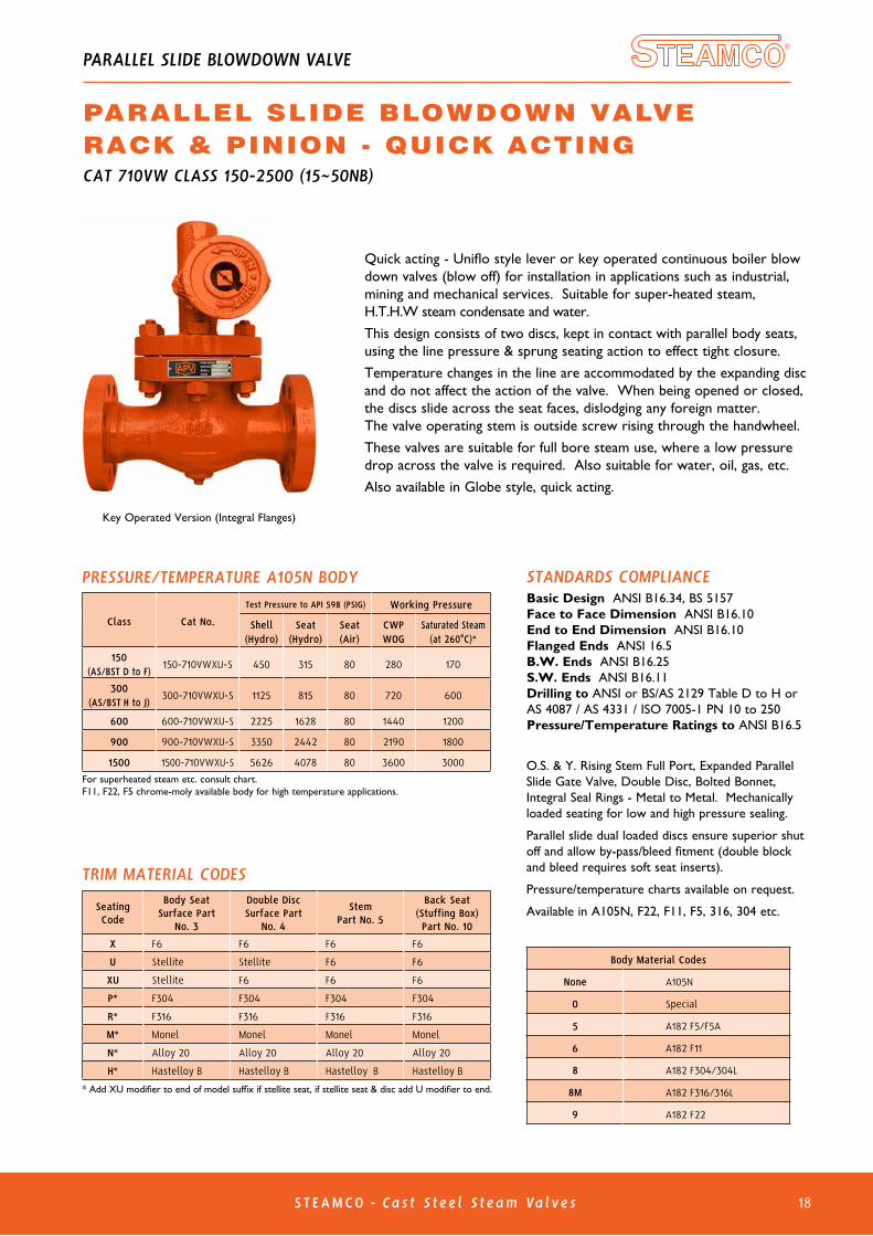
STANDARDS COMPLIANCEBasic Design ANSI B16.34, BS 5157Face to Face Dimension ANSI B16.10End to End Dimension ANSI B16.10Flanged Ends ANSI 16.5B.W. Ends ANSI B16.25S.W. Ends ANSI B16.11Drilling to ANSI or BS/AS 2129 Table D to H or AS 4087 / AS 4331 / ISO 7005-1 PN 10 to 250 Pressure/Temperature Ratings to ANSI B16.5
O.S. & Y. Rising Stem Full Port, Expanded Parallel Slide Gate Valve, Double Disc, Bolted Bonnet, Integral Seal Rings - Metal to Metal. Mechanically loaded seating for low and high pressure sealing.
Parallel slide dual loaded discs ensure superior shut off and allow by-pass/bleed fitment (double block and bleed requires soft seat inserts).
Pressure/temperature charts available on request.
Available in A105N, F22, F11, F5, 316, 304 etc.
Key Operated Version (Integral Flanges)
SeatingCode
Body SeatSurface Part
No. 3
Double DiscSurface Part
No. 4
StemPart No. 5
Back Seat(Stuffing Box)Part No. 10
X F6 F6 F6 F6
U Stellite Stellite F6 F6
XU Stellite F6 F6 F6
P* F304 F304 F304 F304
R* F316 F316 F316 F316
M* Monel Monel Monel Monel
N* Alloy 20 Alloy 20 Alloy 20 Alloy 20
H* Hastelloy B Hastelloy B Hastelloy B Hastelloy B
TRIM MATERIAL CODES
* Add XU modifier to end of model suffix if stellite seat, if stellite seat & disc add U modifier to end.
Body Material Codes
None A105N
0 Special
5 A182 F5/F5A
6 A182 F11
8 A182 F304/304L
8M A182 F316/316L
9 A182 F22
Quick acting - Uniflo style lever or key operated continuous boiler blow down valves (blow off) for installation in applications such as industrial, mining and mechanical services. Suitable for super-heated steam, H.T.H.W steam condensate and water.
This design consists of two discs, kept in contact with parallel body seats, using the line pressure & sprung seating action to effect tight closure.
Temperature changes in the line are accommodated by the expanding disc and do not affect the action of the valve. When being opened or closed, the discs slide across the seat faces, dislodging any foreign matter. The valve operating stem is outside screw rising through the handwheel.
These valves are suitable for full bore steam use, where a low pressure drop across the valve is required. Also suitable for water, oil, gas, etc.
Also available in Globe style, quick acting.
PARALLEL SLIDE BLOWDOWN VALVERACK & PINION - QUICK ACTING
PARALLEL SLIDE BLOWDOWN VALVE
CAT 710VW CLASS 150-2500 (15~50NB)

ST EAMCO - Ca s t S teel S team Va lves20
Description Material Specs.
Body Carbon Steel A216 Gr. WCB
Bonnet Carbon Steel A216 Gr. WCB
Disc Carbon Steel + HF A216 Gr.WCB + Stellite #12
Stem Stainless Steel 17-4PH
Hand Wheel Ductile Iron A536 Gr. 65-45-12
Seat Carbon Steel + HF A105 + Stellite #6
Back Seat Ring Integral Stellite #6
Yoke Sleeve Ductile Iron or Bronze A439 Gr. D2C or B62
Sleeve Gland Carbon Steel A216 Gr. WCB
Gland Flange Carbon Steel A105
Gland Ring Stainless Steel A276 Gr. 420
Wheel Nut Carbon Steel A105
Bonnet Bolt Carbon Steel A193 Gr. B7/B7M
Bonnet Nut Carbon Steel A194 Gr. 2H/2HM
Gland Bolt Carbon Steel A193 Gr. B7
Gland Nut Carbon Steel A194 Gr. 2H
Gland Bolt Pin Carbon Steel A108 Gr. 1020
Bearing - Thrust Ball
Grease Nipple Carbon Steel A307 Gr. B
Set Screw Carbon Steel A307 Gr. B
Name Plate Stainless Steel 304/AL
Packing Asbestos Free Reinforced Graphite*
Gasket Spiral Wound 316 Graphite filled
Standards
Face to Face/End to End ANSI B16.10
Flange Dimensions ANSI B16.5
Basic Design API 600/ISO 10434
Testing API 598
Size (in) 1-1/2” 2” 2-1/2” 3” 4” 5” 6” 8” 10” 12” 14” 16”
A. Face to Face RF 190 216 241 283 305 381 403 419 457 502 762 838
A. Face to Face RTJ 203 232 257 298 321 397 419 435 473 518 788 854
A. End to End BW 190 216 241 283 305 381 403 419 457 502 762 838
B. Valve Open 365 429 457 527 619 800 829 1025 1213 1473 1289 1784
C. Hand Wheel Dia 229 229 229 254 305 350 406 457 508 559 559 559
Weight (Kg) RF/RTJ 20 24 44 50 74 106 137 217 337 580 715 1050
Weight (Kg) BW 16 20 35 37 54 100 110 174 285 495 615 940
Size (in) 18” 20” 24”
A. Face to Face RF 914 991 1143
A. Face to Face RTJ 930 1010 1165
A. End to End BW 914 991 1143
B. Valve Open 1965 2194 2578
C. Hand Wheel Dia 610 660 660
Weight (Kg) RF/RTJ 1235 1655 2320
Weight (Kg) BW 1090 1500 2100
* -180°C to 450°C Chesterton #1600 packing
C
B
A
GEOTHERMAL GATE VALVE
GATE VALVE GEOTHERMAL TRIMCAT AP33XXXXXXXXX-XGE CLASS 300 RISING STEM, NON RISING HANDWHEEL OS&Y OUTSIDE SCREW & YOKE FULL PORT DESIGN (SPECIAL LARGE BORE ALSO AVAILABLE) FLEXIBLE WEDGE
DIMENSIONS (MM)
DIMENSIONS (MM)

ST EAMCO - Ca s t S teel S team Va lves 22
OVERALL DIMENSIONS (MM & IN) & WEIGHT (KG)
*Available in undrilled to accommodate AS/BS or PN/JIS table drilling. ANSI flanges can also be machined to AS/BS table thickness to allow face to face dimension alteration. 1/2” to 1-1/2” see page 44 of APV Cast, Gate, Globe, Check Catalogue (Full Version).
VALVE SIZE (NPS)inch 2 2-1/2 3 4 5 6 8 10 12mm 50 65 80 100 125 150 200 250 300
CLASS 150*(Table D TO F)
A-A1
(RF-BW)inch 8 8-1/2 9-1/2 11-1/2 14 16 19-1/2 24-1/2 27-1/2mm 203 216 241 292 356 406 495 622 698.5
B (Open)inch 13-3/4 14-7/8 16 17-7/8 22-3/8 22-1/2 24-7/8 29-1/8 39-3/8mm 349 378 407 454 569 573 632 740 1000
Cinch 8 10 10 12 15 16 18 20 20mm 200 250 250 300 390 400 450 500 500
Weight(kg)
inch 22 31 37 58 103 111 179 240 410mm 19 25 26 50 95 101 159 215 370
CLASS 300*(Table F TO H)
A-A1
(RF-BW)inch 10-1/2 11-1/2 12-1/2 14 15-3/4 17-1/2 22 24-1/2 28mm 267 292 318 356 400 444.5 559 622 711
B (Open)inch 14-1/4 15-1/2 16-7/8 19 26-3/8 26-5/8 30-1/2 40-7/8 54-1/8mm 362 394 429 482 669 676 774 1040 1375
Cinch 8 10 12 14 16.9 18 20 20 20mm 200 250 300 350 430 450 500 500 500
Weight(kg)
inch 28 47 54 76 150 162 270 340 550mm 22 40 43 61 130 136 232 280 520
CLASS 600*
A-A1
(RF-BW)inch 11-1/2 13 14 17 22 26 31 33mm 292 330 356 432 559 660 787 838
A (RTJ)inch 11-5/8 13-1/8 14-1/8 17-1/8 22-1/8 26-1/8 31-1/8 33-1/8mm 295 333 359 435 562 664 791 841
B (Open)inch 19-1/2 21-1/8 23-1/4 28-1/8 38-5/8 44-3/4 50-3/32 58-2/3mm 495 537 590 714 981 1136 1276 1490
Cinch 10 12 14 16 22 24 24 26-7/8mm 250 300 350 400 550 600 600 680
Weight(kg)
inch 51 62 85 143 340 520 720 950mm 42 51 72 120 284 465 580 830
FEATURESScrew-Down Non-Return Globe ValveGuided loose disc for combination check & stop.Bolted Bonnet, O.S. & Y., Swivel Disc.
STANDARDS COMPLIANCEBasic Design API 600/BS 1873 & ANSI B16.34Face to Face Dimension ANSI B16.10End to End Dimension ANSI B16.10Flanged Ends ANSI 16.5B.W. Ends ANSI B16.25Drilling to ANSI or BS/AS 2129 Table D to H or AS 4087/AS 4331.1/ISO 7005-1/EN 1092-1/PN10 to PN100
* Fitted on larger sizes & higher classes. † Gearboxes on larger sizes .
STANDARD MATERIAL SPECIFICATIONSPart Name Materials
1 Body ASTM A216 Gr. WCB2 Seat Ring ASTM A105 with HF overlay3 Disc ASTM A105 with F6 overlay4 Stem ASTM A182 Gr. F65 Gasket Spiral Wound 316/GRP6 Gasket Ring Joint CAD Plated7 Bonnet ASTM A216 Gr. WCB (or WC6)8 Bonnet Bolt ASTM A193 Gr. B79 Bonnet Nut ASTM A194 Gr. 2H 10 Back Seat Bushing ASTM A182 Gr. F611 Stem Packing Braided graphite (top & Bottom)12 Stem Packing Flexible graphite
13* Lantern Ring ASTM A182 Gr. F614 Pin ASTM A182 Gr. F615 Gland ASTM A182 Gr. F616 Gland Flange ASTM A216 Gr. WCB17 Gland Bolt ASTM A193 Gr. B718 Gland Nut ASTM A194 Gr. 2H19 Yoke Bush Gr. D2C or Bronze B62
20† Handwheel A536/A19721 Wheel Nut ASTM A105
22* Torque Arm ASTM A10523 Guided Spring InconelX750 - Optional
WORKING PRESSUREP143XXXXXXXXXX XU-D 150 CLASS280 PSI CWP (WOG)170 PSI Saturated Steam (at 260ºC)
P151XXXXXXXXXX XU-D 300 CLASS720 PSI CWP (WOG)600 PSI Saturated Steam (at 260ºC)
P171XXXXXXXXXX XU-D 600 CLASS1440 PSI CWP (WOG) 1100 psi at 260°C, 825 psi at 400°C.
For horizontal installations in applications such as industrial, mining and mechanical services, suitable for H.T.H.W., steam, condensate and water.
B
C
A1
2
3
4
65
7
98
10
11
12
13
14
15
16
17
18
19
20
21
SDNR GLOBE VALVE
STOP CHECK GLOBE VALVE SCREW DOWN NON RETURNCAT P143XXXXXXXXXX-D/P151XXXXXXXXXX-D/P171XXXXXXXXXX-D CLASS 150-600
Buttweld ends
Guided Disc
Optional Spring Assisted (SDNR)
23

ST EAMCO - Ca s t S teel S team Va lves27
Globe Valve (combination globe & check valve), Bolted Bonnet, O.S. & Y., Swivel Disc (guided loose disc for combination check & stop). Can also be supplied as standard globe stop valve. Drilling to ANSI, AS 2129 Table D to H or AS 4331.1 /ISO 7005-1 / AS 4087 PN10 to 100.
WORKING PRESSUREP143XXXXXXR 150 CLASS280 PSI CWP (WOG)170 PSI Saturated Steam (at 260ºC)P151XXXXXXR 300 CLASS 720 PSI CWP (WOG)600 PSI Saturated Steam (at 260ºC)For superheated steam consult pressure/temp chartP171XXXXXXR 600 CLASS1440 PSI CWP (WOG)
WC6 body is available for high temperature applications, consult P/T chart.
For installations in application such as industrial, mining & mechanical services. Suitable for super-heated steam, H.T.H.W, steam, condensate and water.Stem is guided for smooth operation. Also available in Bronze, Iron, chrome-moly etc.
OVERALL DIMENSIONS (MM) & WEIGHT (KG)
VALVE SIZE (NPS)
inch 2 2-1/2 3 4 5 6 8 10 12
mm 50 65 80 100 125 150 200 250 300
CLASS 150
(Table D TO F)
L* (RF-BW) mm 102/114 108/146 146/159 152/165 178 203/216 241/248 305/311 305/349
B (Open) mm 373 390 420 500 550 565 670 770 880
C mm 200 250 250 300 390 390 450 550 600
O mm 152 178 191 229 254 279 343 406 483
Weight (kg)RF 22 31 377 58 103 111 179 240
BW 19 25 26 50 95 101 159 215 35
CLASS300
(Table F TO H)
L* (RF-BW) mm 133 127/146 140/159 146/178 178/191 222 267/279 311 349/355
B (Open) mm 390 425 485 580 700 770 900 1020 700
C mm 200 250 300 350 430 450 500 600 600
O mm 165 191 210 254 279 318 381 445 520
Weight (kg)RF 28 47 54 76 150 162 270
BW 22 40 43 61 130 136 232 394
CLASS600
L* (RF-BW) mm 146 165 178 216 279 330 394 419
B (Open) mm 423 498 575 750 1030 1290 1300 1504
C mm 250 300 350 450 600 650 650 650
O mm 165 191 210 273 356 419 510 560
Weight (kg)RF 51 62 85 143 340 520
BW 42 51 72 120 284 465
STANDARD MATERIAL SPECIFICATIONS
* Two patterns are available hence 2 dimensions have been shown.15 to 40NB and 350 to 400NB also available, refer to drawing.
STANDARDS COMPLIANCEBasic Design BS 1873/ANSI B16.34Test API Standard 598 Flanged Ends ANSI B16.5 or BS/AS/PNB.W. Ends ANSI B16.25Face to Face Dimension BS 2820 or ANSI B16.10Pressure/Temperature Ratings to ANSI B16.34.
Customer must specify flow direction
(Horizontal or Vertical)
RIGHT ANGLE GLOBE VALVECAT P143XXXXXX-R/P151XXXXXX-R/P171XXXXXX-R CLASS 150-600
RIGHT ANGLE GLOBE VALVE
Buttweld ends
No Part Material
1 Body ASTM A216 WCB
2 Seat ASTM A105+STL#6 overlay
3 Disc ASTM A105+13CR
4 Disc Cover ASTM A276 410
5 Stem ASTM A182 F6A
6 Gasket SS316+Graphite
7 Bonnet ASTM A216 WCB
8 Back Seat ASTM A276 410
9 Bolt ASTM A193 B7
10 Nut ASTM A194 2H
11 Packing Graphite
12 Gland ASTM A216 410
13 Gland Flange ASTM A216 WCB
14 Bolt ASTM A193 B7
15 Nut ASTM A194 2H
16 Pin AISI 1035
17 Stem Nut Copper Alloy
18 Set Screw ASTM A193 B7
19 Handwheel Malleable Iron
20 Washer A3+ZP
21 Locking Nut ASTM A194 2H
22 Guide Pin AISI 1035
23 Guide Cage AISI 1035
Note: Other body & trim materials are available upon request, such as bronze.
15 1416
1
2
3
4
5
6
7
8
109
12
11
17
18
19
13
22 23
2120
1.6
Od
L*
L*B
C
t
n-ø

ST EAMCO - Ca s t S teel S team Va lves 33
Non return Piston Check valve, lift type, bolted bonnet, guided disc. Flange drilling ANSI 150 to 600 and AS2129 table D to H and PN10 to 100.For horizontal installations in applications such as industrial, mining and mechanical services. Suitable for super-heated steam, H.T.H.W., steam, condensate and water.Guiding of stem assures smooth operation.Other body materials like Bronze and WC6 also available.
*1 Spring Optional. *2 Drain Optional.
WORKING PRESSURESLCLXU-Z 150 CLASS280 PSI CWP (WOG)170 PSI Saturated Steam (at 260°C)SLCLXU-Z 300 CLASS 720 PSI CWP (WOG)600 PSI Saturated Steam (at 260°C)For superheated steam consult pressure/temp chartSLCLXU-Z 600 CLASS1440 PSI CWP (WOG)1100 PSI at 260°C, 825 psi at 400°C. Consult chart for other temperaturesWC6 body is available for high temperature applications
OVERALL DIMENSIONS (MM & INCHES) & WEIGHT (KG)
STANDARD MATERIAL SPECIFICATIONS
Buttweld ends
VALVE SIZE (NPS)inch 2 2-1/2 3 4 5 6 8 10 12mm 50 65 80 100 125 150 200 250 300
CLASS 150(Table D to F)
(PN10~21)
A-A1(RF-BW)
inch 8 8-1/2 9-1/2 11-1/2 14 16 19-1/2 24-1/2 27-1/2
mm 203 216 241 292 356 406 495 622 698.5
Binch 6-7/8 7 7-1/2 8-5/8 9-1/4 12-3/4 15-1/8 17-5/8 21-1/4
mm 175 178 191 219 235 324 384 448 540
Weight(kg)
RF 20 24 35 55 84 96 160 245 345
BW 14 17 26 37 52 80 133 213 294
CLASS 300(Table F to H)(PN25~50)
A-A1(RF-BW)
inch 10-1/2 11-1/2 12-1/2 14 15-3/4 17-1/2 21 24-1/2 28
mm 267 292 318 356 400 444 533 622 711
Binch 7-3/4 8 8-3/4 10-7/8 11-5/8 13-1/4 16-1/4 18-1/4 22-1/8
mm 197 203 222 276 295 337 413 464 562
Weight(kg)
RF 35 37 60 82 110 155 268 380 495
BW 32 35 50 65 70 128 230 270 460
CLASS 600(PN50~100)
A-A1(RF-BW)
inch 11-1/2 13 14 17 20 22 26 31 33
mm 292 330 356 432 508 559 660 787 838
Binch 8-1/4 8-5/8 10-1/2 11-3/4 13-1/4 15 18-3/4 21-5/8 22-5/8
mm 210 219 267 299 337 381 476 549 670
Weight(kg)
RF 40 55 72 120 175 270 420 620 810
BW 31 45 60 85 125 225 365 500 715
Part Material
1 Body ASTM A216 Gr. WCB 2 Seat Ring ASTM A105 with HF overlay
3/4 Disc/Stem ASTM A105 with F6 overlay5 Gasket Stainless Steel/Graphite6 Bonnet/Guide ASTM A216 Gr. WCB 7 Bonnet Nut ASTM A194 Gr. 2H8 Bonnet Bolt ASTM A193 Gr. B7
9*1 Spring Inconel X75010 Gasket Graphite
11*2 Drain Plug A105N
STANDARDS COMPLIANCEBasic Design API 600/BS 1873 and ANSI B16.34Face to Face Dimension ANSI B16.10End to End Dimension ANSI B16.10Flanged Ends ANSI 16.5B.W. Ends ANSI B16.25Drilling to ANSI or BS/AS 2129 Table D to H and PN10 to 100
PISTON CHECK VALVE
PISTON CHECK - LIFT TYPECAT SLCL CLASS 150-600
SLCL-ZSpring Activated
B
1
2
3
4 5
6
7
8
9
10 11
Drain Hole
(Guiding mechanism varies according to size class, refer to drawing)
A
1
3
5
6
8
7
9
4
2
10 11

ST EAMCO - Ca s t S teel S team Va lves34
WORKING PRESSURESLCLXU-Z 150 CLASS 280 PSI CWP (WOG)170 PSI Saturated Steam (at 260°C)SLCLXU-Z 300 CLASS 720 PSI CWP (WOG)600 PSI Saturated Steam (at 260°C)For superheated steam consult pressure/temp chartSLCLXU-Z 600 CLASS1440 PSI CWP (WOG)1100 PSI at 260°C, 825 psi at 400°C. Consult chart for other temperaturesWC6 body is available for high temperature applications
OVERALL DIMENSIONS (MM & INCHES) & WEIGHT (KG)
VALVE SIZE (NPS)inch 2 2-1/2 3 4 5 6 8 10 12mm 50 65 80 100 125 150 200 250 300
CLASS 150(Table D to F)
(PN10~21)
A-A1 (RF-BW)inch 8 8-1/2 9-1/2 11-1/2 14 16 19-1/2 24-1/2 27-1/2mm 203 216 241 292 356 406 495 622 698.5
Binch 6-7/8 7 7-1/2 8-5/8 9-1/4 12-3/4 15-1/8 17-5/8 21-1/4mm 175 178 191 219 235 324 384 448 540
Weight (kg)RF 20 24 35 55 84 96 160 245 345BW 14 17 26 37 52 80 133 213 294
CLASS 300(Table F to H)(PN25~50)
A-A1 (RF-BW)inch 10-1/2 11-1/2 12-1/2 14 15-3/4 17-1/2 21 24-1/2 28mm 267 292 318 356 400 444 533 622 711
Binch 7-3/4 8 8-3/4 10-7/8 11-5/8 13-1/4 16-1/4 18-1/4 22-1/8mm 197 203 222 276 295 337 413 464 562
Weight (kg)RF 35 37 60 82 110 155 268 380 495BW 32 35 50 65 70 128 230 270 460
CLASS 600(PN50~100)
A-A1 (RF-BW)inch 11-1/2 13 14 17 20 22 26 31 33mm 292 330 356 432 508 559 660 787 838
Binch 8-1/4 8-5/8 10-1/2 11-3/4 13-1/4 15 18-3/4 21-5/8 22-5/8mm 210 219 267 299 337 381 476 549 670
Weight (kg)RF 40 55 72 120 175 270 420 620 810BW 31 45 60 85 125 225 365 500 715
SLCL-WSpring Activated
Buttweld ends
*1 Spring Optional. *2 Drain Optional.
STANDARD MATERIAL SPECIFICATIONS
Part Material
1 Body/Guide ASTM A216 Gr. WCB 2 Seat Ring ASTM A105 with HF overlay
3/4 Disc/Stem ASTM A105 with F6 overlay5 Gasket Stainless Steel/Graphite6 Bonnet ASTM A216 Gr. WCB 7 Bonnet Nut ASTM A194 Gr. 2H8 Bonnet Bolt ASTM A193 Gr. B7
9*1 Spring Inconel X750 10 Gasket Graphite
11*2 Drain Plug A105N
STANDARDS COMPLIANCEBasic Design API 600/BS 1873 and ANSI B16.34Face to Face Dimension ANSI B16.10End to End Dimension ANSI B16.10Flanged Ends ANSI 16.5B.W. Ends ANSI B16.25Drilling to ANSI, BS/AS 2129 Table D to H or PN10 to 100
Non return Piston Check valve, lift type, bolted bonnet, guided disc. Flange drilling ANSI 150 to 600 & BS/AS2129 table D to H, and PN10 to 100.
For horizontal installations in applications such as industrial, mining and mechanical services. Suitable for super-heated steam, H.T.H.W., steam, condensate and water.
Guiding of stem assures smooth operation.
Other body materials like Bronze and WC6 also available. (S-Bend Type Body shown)
PISTON CHECK - LIFT TYPE
PISTON CHECK VALVE
CAT SLCL-W CLASS 150-600
A
B
8
7
6
5
4
3
2
1
9
10 11
1
2
3
4
9
5
6
7
8
10 11

ST EAMCO - Ca s t S teel S team Va lves 36
BELLOW SEALED GLOBE VALVE
GLOBE VALVE BELLOW SEALED BOLTED BONNET
1
2
3
4
5
7
8
9
10
11
12
13
14
15
16
17
18
19
20
21
22
23
24
SEAL WELD
SEAL WELDSEAL WELD
TACK WELD
6
• Inconel or 321SS Bellows - For longer life - Maximum corrosion resistance• Flanged, screwed or welded end connections• Welded or bolted bonnet design• Zero stem leakage - Eliminates media loss - Satisfies environmental regulations• Zero maintenance - Lower operating costs/no downtime• Three stem seals for safety - Metallic bellows - Graphite packing - Backseat in open position
• Reduce monitoring costs• Hardfaced seating surface - Stellite 6 for long life• Valve designed, manufactured and tested - To ANSI B16.34/API 602 & 598• Additional alloy and trims available• For applications where leakage into or out of the valve is unacceptable - Heat transfer oil - Toxic fluids - Steam - Regulated media
DESIGN FEATURES
OVERVIEW• ASME B16.34 Design• 15NB - 50NB (1/2 - 2”) Bolted Bonnet• Flange Ends, SW, NPT, BSP or Buttweld ends available 150 to 2500 Class• Design - API 602, BS 5352, MSS SP11, ANSI/ASME B16.34• End Connections - Socket Weld - ANSI/ASME B16.11 Thread - ANSI/ASME B1.20.1 Butt Weld - ANSI/ASME B16.25 Flange - ANSI/ASME B16.5• Test and Inspection - API 598 / BS 5146
No. Part Name
1 Body2 Disc3 Split Ring4 Disc Nut5 Gasket6 Bellows Holder Lower7 Bonnet Bolt8 Bellows9 Stem*10 Bonnet11 Bonnet Upper12 Guide Pin13 Gland Packing**14 Yoke15 Gland16 Gland Flange17 Gland Nut18 Gland Bolt19 Thrust Washer20 Yoke Sleeve21 Handwheel22 Handwheel Washer23 Name Plate24 Handwheel Nut
MATERIALS
* Stem Smoothness ≤ Ra 0.80 µm** Stuffing Box Smoothness ≤ Ra 3.2 µm

ST EAMCO - Ca s t S teel S team Va lves37
GATE VALVE BELLOW SEALED
BELLOW SEALED GATE VALVE
BOLTED BONNET
1
2
3
5
8
9
10
11
12
14
15
16
17
18
19
20
21
22
23
24
7
SEAL WELD
SEAL WELDSEAL WELD
TACK WELD
6
No. Part Name
1 Body2 Disc3 Split Ring5 Gasket6 Bellows Holder Lower7 Bonnet Bolt8 Bellows9 Stem*10 Bonnet11 Bonnet Upper13 Gland Packing**14 Yoke15 Gland16 Gland Flange17 Gland Nut18 Gland Bolt19 Thrust Washer20 Yoke Sleeve21 Handwheel22 Handwheel Washer23 Name Plate24 Handwheel Nut
• Inconel or 321SS Bellows - For longer life - Maximum corrosion resistance• Flanged, screwed or welded end connections• Welded or bolted bonnet design• Zero stem leakage - Eliminates media loss - Satisfies environmental regulations• Zero maintenance - Lower operating costs/no downtime• Three stem seals for safety - Metallic bellows - Graphite packing - Backseat in open position
• Reduce monitoring costs• Hardfaced seating surface - Stellite 6 for long life• Valve designed, manufactured and tested - To ANSI B16.34/API 602 & 598• Additional alloy and trims available• For applications where leakage into or out of the valve is unacceptable - Heat transfer oil - Toxic fluids - Steam - Regulated media
DESIGN FEATURES
OVERVIEW• ASME B16.34 Design• 15NB - 50NB (1/2 - 2”) Bolted Bonnet• Flange Ends, SW, NPT, BSP or Buttweld ends available 150 to 2500 Class• Design - API 602, BS 5352, MSS SP11, ANSI/ASME B16.34• End Connections - Socket Weld - ANSI/ASME B16.11 Thread - ANSI/ASME B1.20.1 Butt Weld - ANSI/ASME B16.25 Flange - ANSI/ASME B16.5• Test and Inspection - API 598 / BS 5146
MATERIALS
* Stem Smoothness ≤ Ra 0.80 µm** Stuffing Box Smoothness ≤ Ra 3.2 µm

View our catalogues at www.australianpipelinevalve.com.au
AUSTRALIAN PIPELINE VALVE BRAND RANGE - CATALOGUES
APV FAMILY OF BRANDS RANGE - CATALOGUES
COMPLETE PRODUCT LINE
“Australian Pipeline Valve
produces isolation,
control and flow reversal
protection products for
severe and critical service
media in utility, steam,
pipelines, oil & gas
and process industries.
APV valves and pipeline
products form the most
competitive portfolio
in the market.”
Oilfield Products Valves & Wellheads
Gate, Globe & Check Valves - Forged Steel
Plug Valves Lubricated, Sleeved & Lined
Gate, Globe & Check Valves - Cast Steel
Diamond Gear Gearboxes
Flowturn Gate, Globe & Check Valves
Flowturn Instrument Valves
Flowturn Ball Valves Multiway & Deadman
Flowturn Strainers & Sight Glasses
Supercheck Wafer Check Valves
Superseal Butterfly Valves
Steamco Steam Valves
Superseal Industrial Ball Valves
TwinLok Tube Fittings Uniflo Check ValvesTorqturn Actuators
Ball Valves Floating & Trunnion Mounted
Ball Valves Floating Small Bore
Ball ValvesSpecial Service
Product Brochure
Contact us for your local stockist/distributor

www.australianpipelinevalve.com.au
QUALITY ASSURANCE AND CERTIFICATIONWe are continually improving all facets of quality assurance. Full metallurgical and test certificates are always supplied for all pressure retaining parts, we also provide it on all major trim components.
We have endeavoured to provide a broad outline of our range and capabilities. Because we are continually developing new products for our customers this catalogue will, to some extent be incomplete. This catalogue is a general overview only, individual drawings and data sheets can be furnished on request.
If you have any requirement in the field of valves, please contact us for a prompt response. Continuous development ofAustralian Pipeline Valve products may necessitate changes in the design or manufacturing processes. Australian Pipeline Valve reserves the right to effect any such changes without prior notice.
© Australian Pipeline Valve 1990 - 2021 Edition
LOCAL DISTRIBUTOR
A D E L A I D E • B R I S B A N E • P E R T H
Global Supply Line is distributor & stockist, supplying worldwide. Full stock list on line www.globalsupplyline.com.au
Contact email: [email protected]