since 1864 cast steel valves jenkins … · jenkins gate valves offer the ultimate in dependable...
TRANSCRIPT

www.autho
rized
parts
.com
JENKINS
SINCE 1864
®
Installation, Marking and Identification
Marking and identification of Jenkins steel valves conforms to ANSI 16.34 Standard Marking System for Valves, Fittings, Flanges and Unions�(MSS SP-25) as well as the appropriate BS valve standard.
It is important to properly identify valves in service to allow for the ordering of replacement parts or address questions or concerns relatingto our products. Body markings and information shown on the identification plate helps to properly identify valves, allowing timely and accurateresponses to such inquiries.
Integrally cast body marking data includes the following information and helps to provide traceability:• Jenkins logo• Pressure class• Valve size• “Steel” symbol for the grade of material (i.e. WCB for carbon steel)• Heat number – on body and bonnet (cast or stamped)
The body markings are supplemented by an identification plate which, depending on valve type and size, is mounted in the most practicableposition. Tag location for gate and globe valves is typically on the valve yoke. Check valve tags are typically mounted on the rim cap.
Identification plates bear the following information:• Catalog number• Valve size• Body material• Disc material• Stem material• Seat and trim material• Fluid recommendation• Pressure and temperature rating
When purchasing valves, reference should also be made to MSS SP-92, “Valve User Guide.” Inquiries relating specifically to Jenkins prod-�ucts may be referred to our factory or customer service department.
Cast Steel Valves
Product Marking
I.D. Tag Marking Information
JENKINSCAT. NO.
SIZE0
100° FPSI/ °F MAX
PSISTEM
DISCBODY
ASME B16.34 / API 600
XXXXXX
SEAT(SIZE)JENKINSSTEEL
(MATERIAL)(CLASS)
(ID)XXXXX YY
zzz
Heat Number
Cast Bonnet MarkingMaterial SymbolPattern NumberFoundry SymbolHeat Number (cast or stamped)(Not on flange edge unless recessed)
I.D. Tag
Ring Joint Number(Stamped)When applicable
Serial Number(Stamped)
Cast or Stampedon raised pad
-3-
WWW.AUTHORIZEDPARTS.COM
WWW.AUTHORIZEDPARTS.COM

www.autho
rized
parts
.com
JENKINS
SINCE 1864
®
General Information • Class 150, 300 and 600 Valves
Cast Steel Gate Valves
• Standard material is ASTM A216 Grade WCB.• Standard trim is XU (13% CR to hardface) which is suitable for a wide range of applications.• See Engineering Data section for end flange dimensions and drilling templates.
-4-
Flexible Wedge• Compensates for deformation of body due to pipe stresses• Will not stick when valve is closed hot and allowed to cool
Welded-in Seat Ring• Seat ring is seal welded to eliminate leak path.
These valves comply with the applicable requirements of the following standards:• API 600• API 598• ANSI B16.34• ANSI B16.10• ANSI B16.5
Features
Basic Standards
Every Jenkins cast steel valve is subjected to a 100% pressure test according to API 598 requirements.�Manufacturer’s material test reports and Inspection and Test Certifications are available upon request.�Some of the additional inspections and tests performed are:
Other inspections or tests can be performed or evaluation criteria applied when specified by the customer.
• Random Radiograph Inspection of Body and Bonnet Castings to ASME B16.34 Appendix B.• Random Chemical Composition and Mechanical Properties Verification of Fasteners to ASTMA A-193/A-194.• Liquid Penetrate Inspection of Seat Rings.• Visual Inspection of Casting to MSS-SP-55.• Receiving, In-process, and Final Dimensional Inspections to Relevant Valve Standards.
Inspection Policy for Jenkins Valves
Notes
WWW.AUTHORIZEDPARTS.COM
WWW.AUTHORIZEDPARTS.COM

www.autho
rized
parts
.com
JENKINS
SINCE 1864
®
Typical Bolted Bonnet Gate Valve Features
Cast Steel Gate Valves
1. Body: Body is cast to provide liberal strength to meet operatingconditions and to permit unobstructed flow. Turbulence, ero-sion and pressure drop are minimized.Flanged End-Jenkins cast steel gate valves are available inflanged end and butt weld ends. All flanged and butt weldingend valves are designed to conform to ANSI B16.5 and ANSIB16.34 standards.
2. Integral Yoke & Bonnet: Some designs incorporate a two-piece bonnet and yoke. All bonnet assemblies are cast andfinished to the same exacting tolerances as the bodies foraccurate alignment of stems and ease of sealing. Bonnet jointvaries from flat face gasket-joint to ring-type bonnet joint,depending on class.
3. Seat Rings: Seat rings are seal welded to eliminate leak pathbehind rings and for long trouble-free service. The surfaces areprecision ground to fit accurately with the disc.
4. Disc: One piece flexible disc provides accurate alignment ofmating seating surfaces so the valve can absorb piping strainswithout leakage. Also, it avoids any tendency to stick in theseated position. Valves are also furnished with solid wedgediscs that have proved successful in millions of applications.
5. Stem: The tee-head disc-stem connection prevents lateralstrain on the stem for smooth, easy operation. Accurately cutthreads engage the yoke sleeve for positive control of discposition.
6. Yoke Sleeve
7. Handwheel Nut
8. Yoke Sleeve Retaining Nut
9. Packing: Packing contains corrosion inhibitor to avoid stempitting. Stuffing box is deep, assuring long packing life.
10. Gland: Gland is a two-piece ball-type which exerts even pres-sure on the packing without binding the stem.
11. Gland Flange
12. Gland Eye Bolts: Eyebolts swing aside for ease in repackingthe stuffing box.
13. Gland Eye Bolt Nuts
14. Bonnet Gasket
15. Bonnet Studs: Number is dependent on valve size and class.16. Bonnet Nuts: Number is dependent on valve size and class.
Hydraulic Grease Fitting: Hydraulic grease fitting providesfor lubrication of yoke sleeve bearing surfaces (not shown).
17. Groove-Pin
18. Bonnet Bushing
19.
20.
Handwheel: Gate valves can also be supplied with gear ormotor operators.
-5-
Jenkins gate valves offer the ultimate in dependable service for steam, air, gas, oil, oil vapor, and high pressure installations. All havestraight-through ports to assure minimum turbulence, erosion, and resistance to flow. They are available in a wide variety of trims.
WWW.AUTHORIZEDPARTS.COM
WWW.AUTHORIZEDPARTS.COM
www.autho
rized
parts
.com
JENKINS
SINCE 1864
®
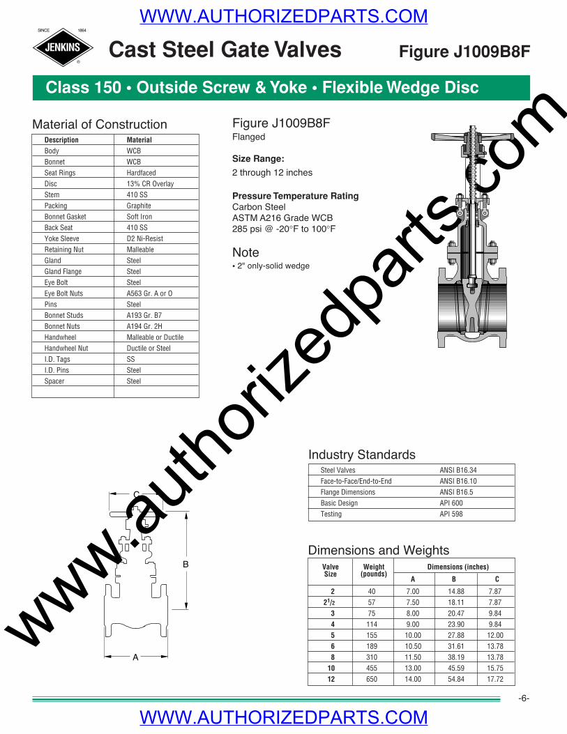
Dimensions and WeightsWeight Dimensions (inches)
(pounds)A B C
2 40 7.00 14.88 7.8721/2 57 7.50 18.11 7.87
3 75 8.00 20.47 9.844 114 9.00 23.90 9.845 155 10.00 27.88 12.006 189 10.50 31.61 13.788 310 11.50 38.19 13.78
10 455 13.00 45.59 15.7512 650 14.00 54.84 17.72
ValveSize
Cast Steel Gate Valves
Class 150 • Outside Screw & Yoke • Flexible Wedge Disc
Figure J1009B8FFlanged
Size Range:
2 through 12 inches
Pressure Temperature RatingCarbon SteelASTM A216 Grade WCB285 psi @ -20°F to 100°F
Note• 2" only-solid wedge
Figure J1009B8F
-6-
Industry StandardsSteel Valves ANSI B16.34Face-to-Face/End-to-End ANSI B16.10Flange Dimensions ANSI B16.5Basic Design API 600Testing API 598
Material of ConstructionDescription Material
Body WCBBonnet WCBSeat Rings HardfacedDisc 13% CR OverlayStem 410 SSPacking GraphiteBonnet Gasket Soft IronBack Seat 410 SSYoke Sleeve D2 Ni-ResistRetaining Nut MalleableGland SteelGland Flange SteelEye Bolt SteelEye Bolt Nuts A563 Gr. A or OPins SteelBonnet Studs A193 Gr. B7Bonnet Nuts A194 Gr. 2HHandwheel Malleable or DuctileHandwheel Nut Ductile or SteelI.D. Tags SSI.D. Pins SteelSpacer Steel
C
B
A
WWW.AUTHORIZEDPARTS.COM
WWW.AUTHORIZEDPARTS.COM
www.autho
rized
parts
.com
JENKINS
SINCE 1864
®
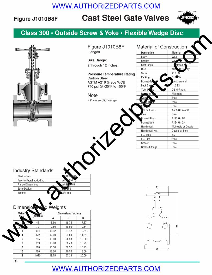
Dimensions and WeightsWeight Dimensions (inches)
(pounds)A B C
2 48 8.50 15.75 7.8721/2 79 9.50 18.98 9.84
3 114 11.12 21.42 9.844 172 12.00 24.80 11.815 235 15.00 28.38 12.006 339 15.88 32.48 15.758 500 16.50 39.57 15.75
10 760 18.00 49.50 18.0012 1020 19.75 57.25 20.00
ValveSize
Figure J1010B8FFlanged
Size Range:
2 through 12 inches
Pressure Temperature RatingCarbon SteelASTM A216 Grade WCB740 psi @ -20°F to 100°F
Note• 2" only-solid wedge
Class 300 • Outside Screw & Yoke • Flexible Wedge Disc
Cast Steel Gate ValvesFigure J1010B8F
-7-
Industry StandardsSteel Valves ANSI B16.34Face-to-Face/End-to-End ANSI B16.10Flange Dimensions ANSI B16.5Basic Design API 600Testing API 598
Material of ConstructionDescription Material
Body WCBBonnet WCBSeat Rings HardfacedDisc 13% CR OverlayStem 410 SSPacking GraphiteBonnet Gasket Spiral WoundBack Seat 410 SSYoke Sleeve D2 Ni-ResistRetaining Nut MalleableGland SteelGland Flange SteelEye Bolt SteelEye Bolt Nuts A563 Gr. A or OPins SteelBonnet Studs A193 Gr. B7Bonnet Nuts A194 Gr. 2HHandwheel Malleable or DuctileHandwheel Nut Ductile or SteelI.D. Tags SSI.D. Pins SteelSpacer SteelGrease Fittings Steel
B
A
C
WWW.AUTHORIZEDPARTS.COM
WWW.AUTHORIZEDPARTS.COM

www.autho
rized
parts
.com
JENKINS
SINCE 1864
®
Dimensions and WeightsWeight Dimensions (inches)
(pounds)A B C
2 84 11.50 18.00 10.0021/2 130 13.00 20.50 10.00
3 160 14.00 22.62 12.004 300 17.00 28.62 14.006 640 22.00 38.62 18.008 1080 26.00 47.25 20.00
10 1550 31.00 58.25 25.0012 2100 33.00 68.12 28.00
Figure J1012B8FFlanged
Size Range:
2 through 12 inches
Pressure Temperature RatingCarbon SteelASTM A216 Grade WCB1480 psi @ -20°F to 100°F
Note• 2" only-solid wedge
ValveSize
Class 600 • Outside Screw & Yoke • Flexible Wedge Disc
Figure J1012B8FCast Steel Gate Valves
-8-
Industry StandardsSteel Valves ANSI B16.34Face-to-Face/End-to-End ANSI B16.10Flange Dimensions ANSI B16.5Basic Design API 600Testing API 598
Material of ConstructionDescription MaterialBody WCBBonnet WCBSeat Rings HardfacedDisc 13% CR OverlayStem 410 SSPacking GraphiteBonnet Gasket Ring JointBack Seat 410 SSYoke Sleeve D2 Ni-ResistRetaining Nut MalleableGland SteelGland Flange SteelEye Bolt SteelEye Bolt Nuts A563 Gr. A or OPins SteelBonnet Studs A193 Gr. B7Bonnet Nuts A194 Gr. 2HHandwheel Malleable or DuctileHandwheel Nut Ductile or SteelI.D. Tags SSI.D. Pins SteelSpacer SteelGrease Fittings Steel
B
A
C
WWW.AUTHORIZEDPARTS.COM
WWW.AUTHORIZEDPARTS.COM

www.autho
rized
parts
.com
JENKINS
SINCE 1864
®
General Information • Class 150, 300 and 600 Valves
Cast Steel Globe Valves
-9-
• Standard material is ASTM A216 Grade WCB.• Standard trim is XU (13% CR to hardface) which is suitable for a wide range of applications.• See Engineering Data section for end flange dimensions and drilling templates.
Welded-in Seat Ring• Seat ring is seal welded to eliminate leak path. behind rings
These valves comply with the applicable requirements of the following standards:• API 598• ANSI B16.34• ANSI B16.10• ANSIB16.5
Features
Basic Standards
Notes
WWW.AUTHORIZEDPARTS.COM
WWW.AUTHORIZEDPARTS.COM
www.autho
rized
parts
.com
JENKINS
SINCE 1864
®
Typical Globe Valve Features
Cast Steel Globe Valves
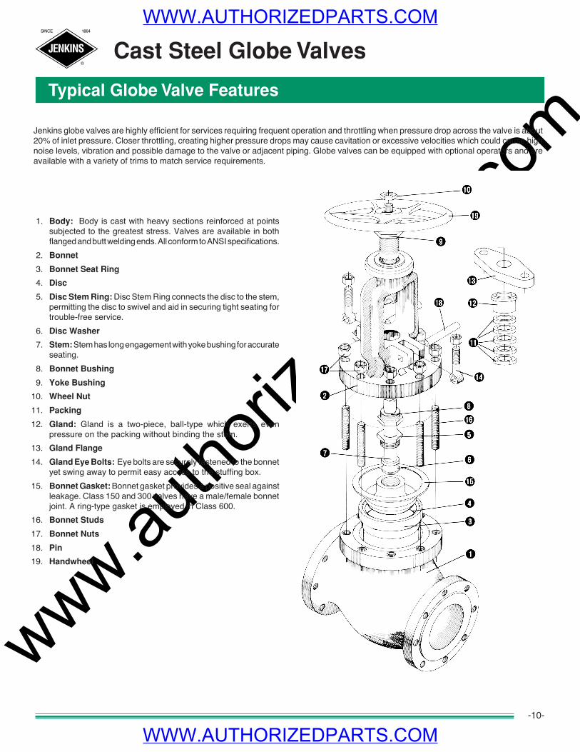
Jenkins globe valves are highly efficient for services requiring frequent operation and throttling when pressure drop across the valve is about20% of inlet pressure. Closer throttling, creating higher pressure drops may cause cavitation or excessive velocities which could cause highnoise levels, vibration and possible damage to the valve or adjacent piping. Globe valves can be equipped with optional operators and areavailable with a variety of trims to match service requirements.
1. Body: Body is cast with heavy sections reinforced at pointssubjected to the greatest stress. Valves are available in bothflanged and butt welding ends. All conform to ANSI specifications.
2. Bonnet
3. Bonnet Seat Ring
4. Disc
5. Disc Stem Ring: Disc Stem Ring connects the disc to the stem,permitting the disc to swivel and aid in securing tight seating fortrouble-free service.
6. Disc Washer
7. Stem: Stem has long engagement with yoke bushing for accurateseating.
8. Bonnet Bushing
9. Yoke Bushing
10. Wheel Nut
11. Packing
12. Gland: Gland is a two-piece, ball-type which exerts evenpressure on the packing without binding the stem.
13. Gland Flange
14. Gland Eye Bolts: Eye bolts are securely fastened to the bonnetyet swing away to permit easy access to the stuffing box.
15. Bonnet Gasket: Bonnet gasket provides a positive seal againstleakage. Class 150 and 300 valves have a male/female bonnetjoint. A ring-type gasket is employed in Class 600.
16. Bonnet Studs
17. Bonnet Nuts
18. Pin
19. Handwheel
-10-
WWW.AUTHORIZEDPARTS.COM
WWW.AUTHORIZEDPARTS.COM
www.autho
rized
parts
.com
JENKINS
SINCE 1864
®
C
B
A
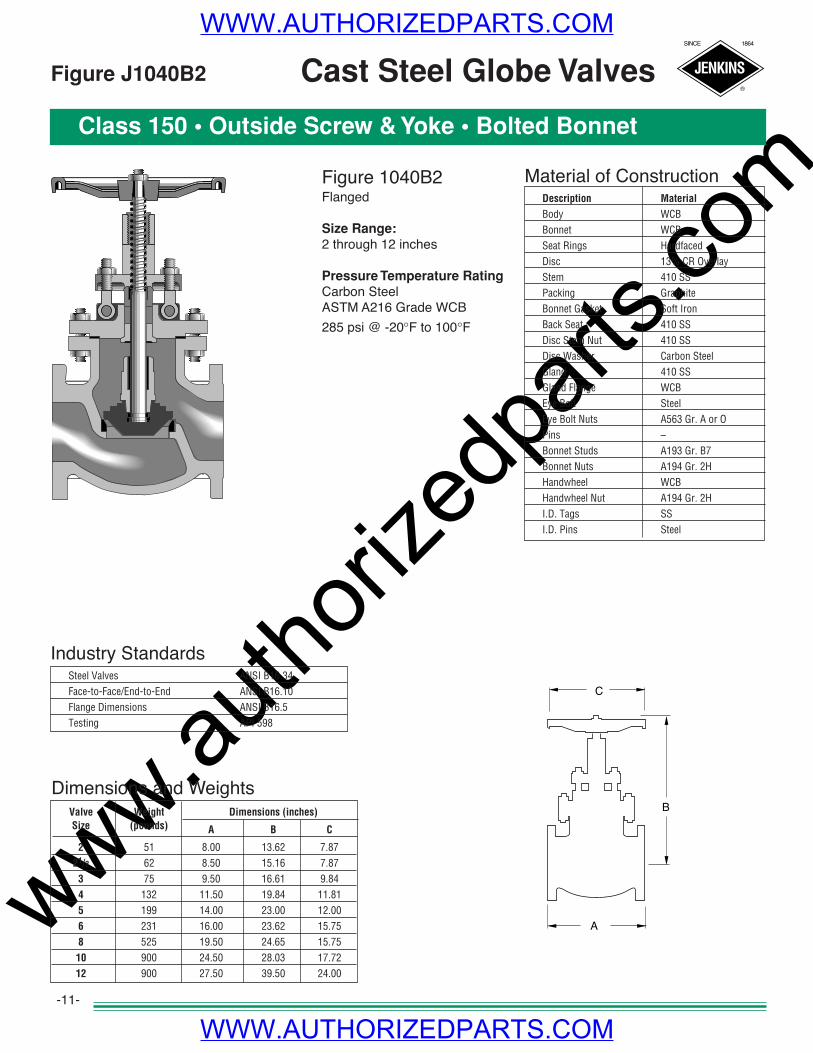
Dimensions and WeightsValve Weight Dimensions (inches)Size (pounds) A B C
2 51 8.00 13.62 7.8721/2 62 8.50 15.16 7.87
3 75 9.50 16.61 9.844 132 11.50 19.84 11.815 199 14.00 23.00 12.006 231 16.00 23.62 15.758 525 19.50 24.65 15.7510 900 24.50 28.03 17.7212 900 27.50 39.50 24.00
Figure 1040B2Flanged
Size Range:2 through 12 inches
Pressure Temperature RatingCarbon SteelASTM A216 Grade WCB285 psi @ -20°F to 100°F
Cast Steel Globe Valves
Class 150 • Outside Screw & Yoke • Bolted Bonnet
Figure J1040B2
-11-
Industry StandardsSteel Valves ANSI B16.34Face-to-Face/End-to-End ANSI B16.10Flange Dimensions ANSI B16.5Testing API 598
Material of ConstructionDescription Material
Body WCBBonnet WCBSeat Rings HardfacedDisc 13% CR OverlayStem 410 SSPacking GraphiteBonnet Gasket Soft IronBack Seat 410 SSDisc Stem Nut 410 SSDisc Washer Carbon SteelGland 410 SSGland Flange WCBEye Bolt SteelEye Bolt Nuts A563 Gr. A or OPins –Bonnet Studs A193 Gr. B7Bonnet Nuts A194 Gr. 2HHandwheel WCBHandwheel Nut A194 Gr. 2HI.D. Tags SSI.D. Pins Steel
WWW.AUTHORIZEDPARTS.COM
WWW.AUTHORIZEDPARTS.COM
www.autho
rized
parts
.com
JENKINS
SINCE 1864
®
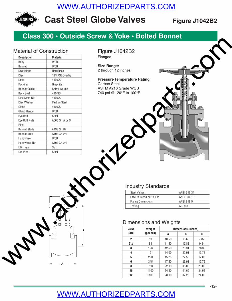
Cast Steel Globe Valves
Dimensions and WeightsValve Weight Dimensions (inches)Size (pounds) A B C
2 59 10.50 16.65 7.8721/2 88 11.50 17.83 9.84
3 128 12.50 20.31 9.844 191 14.00 22.91 13.785 290 15.75 27.50 12.006 345 17.50 25.91 17.728 750 22.00 36.00 20.00
10 1100 24.50 41.65 34.0212 1100 28.00 37.25 24.00
Class 300 • Outside Screw & Yoke • Bolted Bonnet
Figure J1042B2Flanged
Size Range:2 through 12 inches
Pressure Temperature RatingCarbon SteelASTM A216 Grade WCB740 psi @ -20°F to 100°F
Figure J1042B2
-12-
Industry StandardsSteel Valves ANSI B16.34Face-to-Face/End-to-End ANSI B16.10Flange Dimensions ANSI B16.5Testing API 598
Material of ConstructionDescription Material
Body WCBBonnet WCBSeat Rings HardfacedDisc 13% CR OverlayStem 410 SSPacking GraphiteBonnet Gasket Spiral WoundBack Seat 410 SSDisc Stem Nut 410 SSDisc Washer Carbon SteelGland 410 SSGland Flange WCBEye Bolt SteelEye Bolt Nuts A563 Gr. A or OPins –Bonnet Studs A193 Gr. B7Bonnet Nuts A194 Gr. 2HHandwheel WCBHandwheel Nut A194 Gr. 2HI.D. Tags SSI.D. Pins Steel
C
B
A
WWW.AUTHORIZEDPARTS.COM
WWW.AUTHORIZEDPARTS.COM
www.autho
rized
parts
.com
JENKINS
SINCE 1864
®
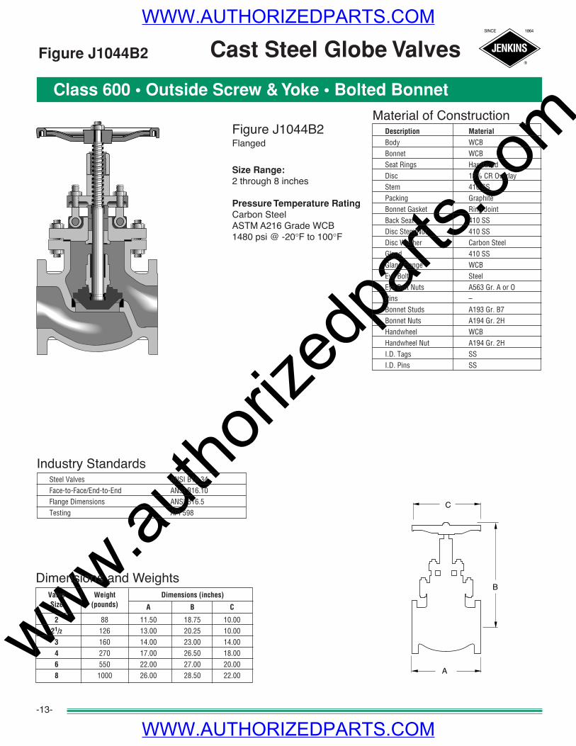
Dimensions and WeightsValve Weight Dimensions (inches)Size (pounds) A B C
2 88 11.50 18.75 10.0021/2 126 13.00 20.25 10.00
3 160 14.00 23.00 14.004 270 17.00 26.50 18.006 550 22.00 27.00 20.008 1000 26.00 28.50 22.00
Figure J1044B2 Cast Steel Globe Valves
Class 600 • Outside Screw & Yoke • Bolted Bonnet
Figure J1044B2Flanged
Size Range:2 through 8 inches
Pressure Temperature RatingCarbon SteelASTM A216 Grade WCB1480 psi @ -20°F to 100°F
-13-
Industry StandardsSteel Valves ANSI B16.34Face-to-Face/End-to-End ANSI B16.10Flange Dimensions ANSI B16.5Testing API 598
Material of ConstructionDescription Material
Body WCBBonnet WCBSeat Rings HardfacedDisc 13% CR OverlayStem 410 SSPacking GraphiteBonnet Gasket Ring JointBack Seat 410 SSDisc Stem Nut 410 SSDisc Washer Carbon SteelGland 410 SSGland Flange WCBEye Bolt SteelEye Bolt Nuts A563 Gr. A or OPins –Bonnet Studs A193 Gr. B7Bonnet Nuts A194 Gr. 2HHandwheel WCBHandwheel Nut A194 Gr. 2HI.D. Tags SSI.D. Pins SS
C
B
A
WWW.AUTHORIZEDPARTS.COM
WWW.AUTHORIZEDPARTS.COM
www.autho
rized
parts
.com
JENKINS
SINCE 1864
®
General Information • Class 150, 300 and 600 Valves
Cast Steel Check Valves
-14-
• Standard material is ASTM A216 Grade WCB.• Standard trim is XU (13% CR to hardface) which is suitable for a wide range of applications.• See Engineering Data section for end flange dimensions and drilling templates.
Disc Type• Class 150 valves-2"-12" and Class 300 valves-sizes 2"-8" feature an internally mounted hinge pin which eliminates a leak path• For class 600 valves, a ring joint bonnet gasket assures positive seal against leakage and accurate alignment of moving parts
Welded-in Seat Ring• Seat ring is seal welded to eliminate leak path. behind rings
These valves comply with the applicable requirements of the following standards:• API 598• ANSI B16.34• ANSI B16.10• ANSI B16.5
Features
Basic Standards
Notes
WWW.AUTHORIZEDPARTS.COM
WWW.AUTHORIZEDPARTS.COM

www.autho
rized
parts
.com
JENKINS
SINCE 1864
®
Typical Swing Check Valve Features
Cast Steel Swing Check Valve
-15-
Check valves are automatically actuated. They are opened and sustained in the open position by the force of velocity pressure, andclosed by the force of gravity. Seating load and resultant tightness is dependent upon back pressure. The disc and associated movingparts may be in a constant state of movement if the velocity pressure is not sufficient to hold the valve in a wide open and stableposition. Premature wear and noisy operation or vibration of the moving parts can be avoided by selecting the size of check valve on thebasis of flow conditions. The minimum velocity required to hold a swing check valve in the wide open and stable position has beendeveloped by analysis of extensive test data and is expressed by the formula:
v= 60 v
The value for v is equal to flow in feet per second and v is the specific volume of fluid in cubic feet per pound. Sizing swing check valveson this basis may often result in the use of valves that are smaller than the pipe in which they are used, necessitating the use of reducersfor installation. The pressure drop will be no greater than that of the larger valve that is only partially open, and valve life will be greatlyextended. The added bonus, of course, is the lower cost of the smaller valve.
There is no tendency for the seating surfaces of swing check valves to gall or score, because the disc meets the flat seat squarelywithout rubbing contact upon closing.
Jenkins cast steel swing check valves can be furnished with outside lever and adjustable weight when so ordered. With the lever andweight mounted so that the weight assists the disc in closing, the valve closes more rapidly when flow stops, thus minimizing reversal offlow and resultant surge and shock. With the lever and weight mounted to balance the weight of the disc, the valve becomes moresensitive to low inlet velocities.
Swing check valves are used to prevent reversal of flow in horizontal or vertical pipe lines. In vertical lines, or for any angle from horizon-tal to vertical, they can be used for upward flow only.
1. Body: Strong construction assuresmaximum safety over the recom-mended pressure and temperaturerange. Both flange and butt weld endsare available.
2. Cap: permits access to hinge anddisc without removing valve from line.
3. Disc: is designed to close on its ownweight to stop backflow from gainingsufficient velocity to create damagingshock.
4. Disc Nut Pin
5. Hinge
6. Cap Studs
7. Cap Stud Nuts
8. Cap Gasket
9. Body Seat Ring (welded in)10. Disc Washer
12. Disc Nut
WWW.AUTHORIZEDPARTS.COM
WWW.AUTHORIZEDPARTS.COM
www.autho
rized
parts
.com
JENKINS
SINCE 1864
®
Dimensions and WeightsValve Weight Dimensions (inches)Size (pounds) A B
2 33 8.00 6.7521/2 57 8.50 7.12
3 59 9.50 7.384 93 11.50 8.505 152 13.00 9.506 165 14.00 10.258 275 19.50 11.8810 440 24.50 13.8812 680 27.50 15.75
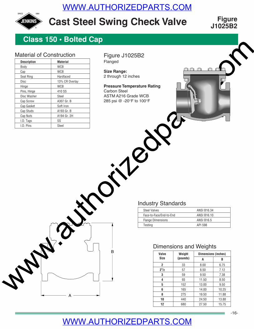
FigureJ1025B2Cast Steel Swing Check Valve
Class 150 • Bolted Cap
Figure J1025B2Flanged
Size Range:2 through 12 inches
Pressure Temperature RatingCarbon SteelASTM A216 Grade WCB285 psi @ -20°F to 100°F
-16-
Industry StandardsSteel Valves ANSI B16.34Face-to-Face/End-to-End ANSI B16.10Flange Dimensions ANSI B16.5Testing API 598
Material of ConstructionDescription Material
Body WCBCap WCBSeat Ring HardfacedDisc 13% CR OverlayHinge WCBPins, Hinge 410 SSDisc Washer SteelCap Screw A307 Gr. BCap Gasket Soft IronCap Studs A193 Gr. BCap Nuts A194 Gr. 2HI.D. Tags SSI.D. Pins Steel
B
A
WWW.AUTHORIZEDPARTS.COM
WWW.AUTHORIZEDPARTS.COM
www.autho
rized
parts
.com
JENKINS
SINCE 1864
®
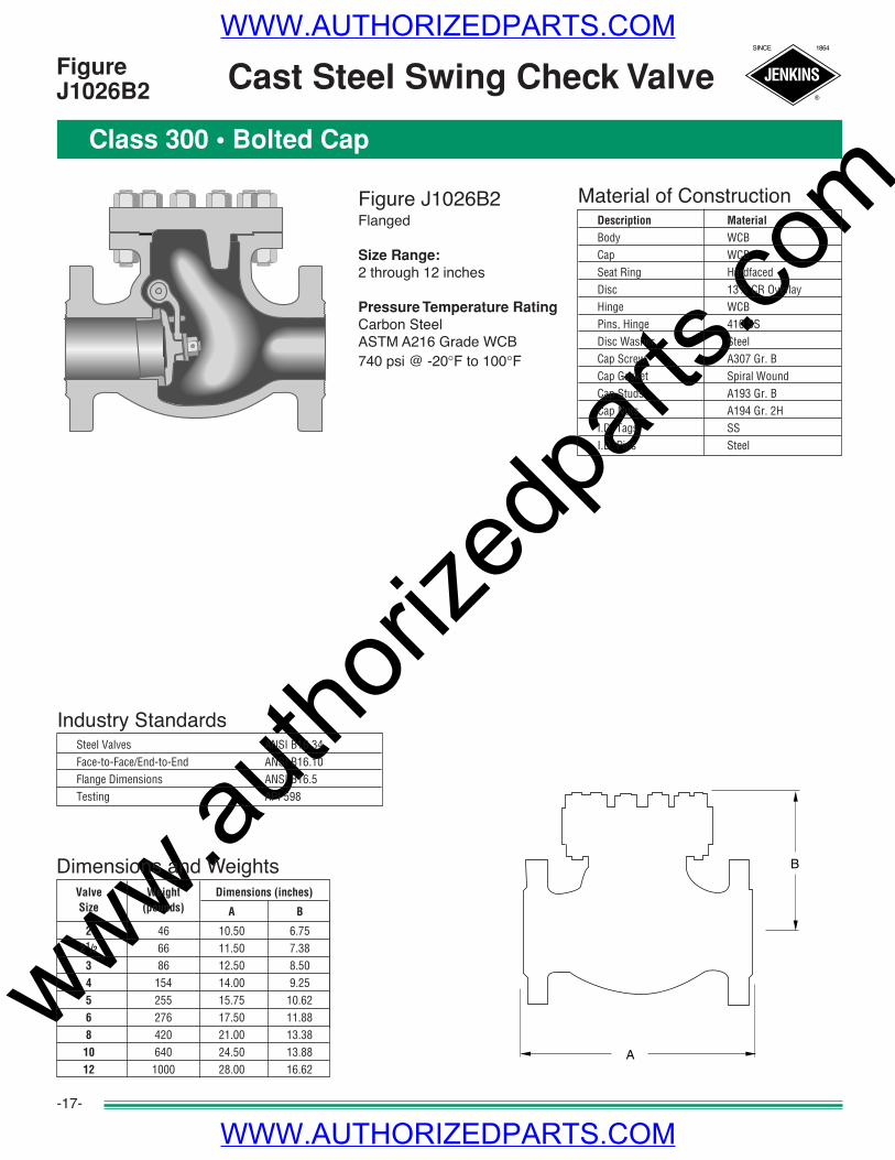
Figure J1026B2Flanged
Size Range:2 through 12 inches
Pressure Temperature RatingCarbon SteelASTM A216 Grade WCB740 psi @ -20°F to 100°F
Material of ConstructionDescription Material
Body WCBCap WCBSeat Ring HardfacedDisc 13% CR OverlayHinge WCBPins, Hinge 410 SSDisc Washer SteelCap Screw A307 Gr. BCap Gasket Spiral WoundCap Studs A193 Gr. BCap Nuts A194 Gr. 2HI.D. Tags SSI.D. Pins Steel
Dimensions and WeightsValve Weight Dimensions (inches)Size (pounds) A B
2 46 10.50 6.7521/2 66 11.50 7.38
3 86 12.50 8.504 154 14.00 9.255 255 15.75 10.626 276 17.50 11.888 420 21.00 13.3810 640 24.50 13.8812 1000 28.00 16.62
FigureJ1026B2 Cast Steel Swing Check Valve
Class 300 • Bolted Cap
-17-
Industry StandardsSteel Valves ANSI B16.34Face-to-Face/End-to-End ANSI B16.10Flange Dimensions ANSI B16.5Testing API 598
B
A
WWW.AUTHORIZEDPARTS.COM
WWW.AUTHORIZEDPARTS.COM
www.autho
rized
parts
.com
JENKINS
SINCE 1864
®
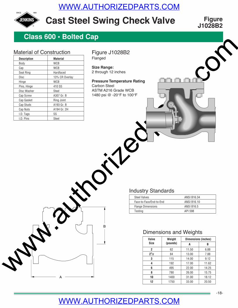
Dimensions and WeightsValve Weight Dimensions (inches)Size (pounds) A B
2 62 11.50 6.8821/2 84 13.00 7.88
3 115 14.00 9.124 192 17.00 11.626 495 22.00 14.258 780 26.00 15.7510 1400 31.00 18.1212 1750 33.00 20.50
Figure J1028B2Flanged
Size Range:2 through 12 inches
Pressure Temperature RatingCarbon SteelASTM A216 Grade WCB1480 psi @ -20°F to 100°F
FigureJ1028B2
Class 600 • Bolted Cap
-18-
Industry StandardsSteel Valves ANSI B16.34Face-to-Face/End-to-End ANSI B16.10Flange Dimensions ANSI B16.5Testing API 598
Material of ConstructionDescription Material
Body WCBCap WCBSeat Ring HardfacedDisc 13% CR OverlayHinge WCBPins, Hinge 410 SSDisc Washer SteelCap Screw A307 Gr. BCap Gasket Ring JointCap Studs A193 Gr. BCap Nuts A194 Gr. 2HI.D. Tags SSI.D. Pins Steel
Cast Steel Swing Check Valve
B
A
WWW.AUTHORIZEDPARTS.COM
WWW.AUTHORIZEDPARTS.COM
www.autho
rized
parts
.com
JENKINS
SINCE 1864
®
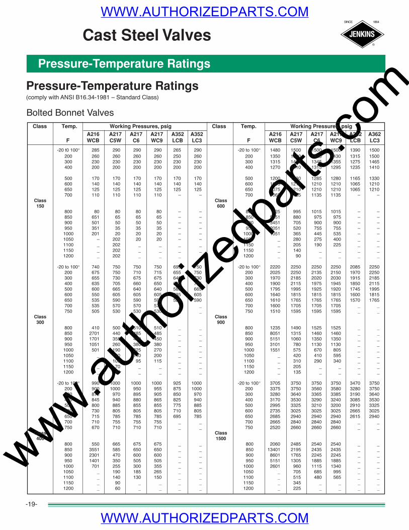
Pressure-Temperature Ratings
Pressure-Temperature Ratings(comply with ANSI B16.34-1981 – Standard Class)
Bolted Bonnet ValvesClass Temp. Working Pressures, psig Class Temp. Working Pressures, psig
A216 A217 A217 A217 A352 A352 A216 A217 A217 A217 A362 A362F WCB C5W C6 WC9 LCB LC3 F WCB C5W C6 WC9 LCB LC3
-20 t0 100° 285 290 290 290 265 290 -20 to 100° 1480 1500 1500 1500 1390 1500200 260 260 260 260 250 260 200 1350 1500 1425 1430 1315 1500300 230 230 230 230 230 230 300 1315 1455 1345 1355 1275 1465400 200 200 200 200 200 200 400 1270 1410 1315 1295 1235 1410
500 170 170 170 170 170 170 500 1200 1330 1285 1280 1165 1330600 140 140 140 140 140 140 600 1095 1210 1210 1210 1065 1210650 125 125 125 125 125 125 650 1075 1210 1210 1210 1065 1210700 110 110 110 110 – – 700 1065 1135 1135 1135 – –
Class Class150 600
800 80 80 80 80 – – 800 825 995 1015 1015 – –850 651 65 65 65 – – 850 5351 880 975 975 – –900 501 50 50 50 – – 900 3451 705 900 900 – –950 351 35 35 35 – – 950 2051 520 755 755 – –1000 201 20 20 20 – – 1000 1051 365 445 535 – –1050 – 202 20 20 – – 1050 _ 280 275 400 _ _1100 _ 202 _ _ _ _ 1150 _ 205 190 225 _ _1150 _ 202 _ _ _ _ 1150 _ 140 _ _ _ _1200 _ 202 _ _ _ _ 1200 _ 90 _ _ _ _
-20 to 100° 740 750 750 750 695 750 -20 to 100° 2220 2250 2250 2250 2085 2250200 675 750 710 715 655 750 200 2025 2250 2135 2150 1970 2250300 655 730 675 675 640 730 300 1970 2185 2020 2030 1915 2185400 635 705 660 650 620 705 400 1900 2115 1975 1945 1850 2115500 600 665 640 640 585 665 500 1795 1995 1925 1920 1745 1995600 550 605 605 605 535 605 600 1640 1815 1815 1815 1600 1815650 535 590 590 590 525 590 650 1610 1765 1765 1765 1570 1765700 535 570 570 570 _ _ 700 1600 1705 1705 1705 _ _750 505 530 530 530 _ _ 750 1510 1595 1595 1595 _ _
Class Class300 900
800 410 500 510 510 _ _ 800 1235 1490 1525 1525 _ _850 2701 440 485 485 _ _ 850 8051 1315 1460 1460 _ _900 1701 355 450 450 _ _ 900 5151 1060 1350 1350 _ _950 1051 260 380 380 _ _ 950 3101 780 1130 1130 _ _1000 501 190 225 270 _ _ 1000 1551 575 670 805 _ _1050 _ 140 140 200 _ _ 1050 _ 420 410 595 _ _1100 _ 105 95 115 _ _ 1100 _ 310 290 340 _ _1150 _ 70 _ _ _ _ 1150 _ 205 _ _ _ _1200 _ 45 _ _ _ _ 1200 _ 135 _ _ _ _
-20 to 100° 990 1000 1000 1000 925 1000 -20 to 100° 3705 3750 3750 3750 3470 3750200 900 1000 950 955 875 1000 200 3375 3750 3560 3580 3280 3750300 875 970 895 905 850 970 300 3280 3640 3365 3385 3190 3640400 845 940 880 865 825 940 400 3170 3530 3290 3240 3085 3530500 800 885 855 855 775 885 500 2995 3325 3210 3200 2910 3325600 730 805 805 805 710 805 600 2735 3025 3025 3025 2665 3025650 715 785 785 785 695 785 650 2685 2940 2940 2940 2615 2940700 710 755 755 755 _ _ 700 2665 2840 2840 2840 _ _750 670 710 710 710 _ _ 750 2520 2660 2660 2660 _ _
Class Class400 1500
800 550 665 675 675 _ _ 800 2060 2485 2540 2540 _ _850 3551 585 650 650 _ _ 850 13401 2195 2435 2435 _ _900 2301 470 600 600 _ _ 900 8601 1765 2245 2245 _ _950 1401 350 505 505 _ _ 950 5151 1305 1885 1885 _ _1000 701 255 300 355 _ _ 1000 2601 960 1115 1340 _ _1050 _ 190 185 265 _ _ 1050 _ 705 685 995 _ _1100 _ 140 130 150 _ _ 1100 _ 515 480 565 _ _1150 _ 90 _ _ _ _ 1150 _ 345 _ _ _ _1200 _ 60 _ _ _ _ 1200 _ 225 _ _ _ _
Cast Steel Valves
-19-
WWW.AUTHORIZEDPARTS.COM
WWW.AUTHORIZEDPARTS.COM

www.autho
rized
parts
.com
JENKINS
SINCE 1864
®
Centigrade to Fahrenheit – Fahrenheit to Centigrade
Locate temperature in middle column. If in degrees Centigrade, read Fahrenheit equivalent in �right-hand column; if in degrees Fahrenheit, read Centigrade equivalent in left-hand column.
Conversion Formulas: °C = 5/9 (°F-32) °F = 9/5 (°C+32)
Temperature Conversions
-20-
Technical Data
WWW.AUTHORIZEDPARTS.COM
WWW.AUTHORIZEDPARTS.COM
www.autho
rized
parts
.com
JENKINS
SINCE 1864
®
-2-
How to Specify and Order the Correct Valves
SizeNominal size of the pipeline into which the valve will be placed must bedetermined. Comprehensive data on flow characteristic and pipe propertiesare contained in the Engineering Data Catalog.
Valve MaterialThe following facts should be considered in determining the correct valvematerial.• The media to be controlled.• The temperature of the media.• The possible extraordinary stresses affecting the valve.• Safety standards and/or piping codes.
Pressure/Temperature RatingPlease pay careful attention that the PRESSURE/TEMPERATURE RATINGSshown on page 19 in this catalog are in keeping with the requirements of theservice.
Valve End ConnectionsConsiderations as to pipeline integrity, future maintenance, corrosion fac-tors, field assembly, weight and safety should be given in determining themethod of connecting the valve in the pipeline.
CAUTION: When servicing, disassembling or disposing of valves containing asbestos gaskets or packing, avoid breathing dust or fibers from these parts.Disposal of asbestos and asbestos related products should comply with local, state and federal laws and regulations.
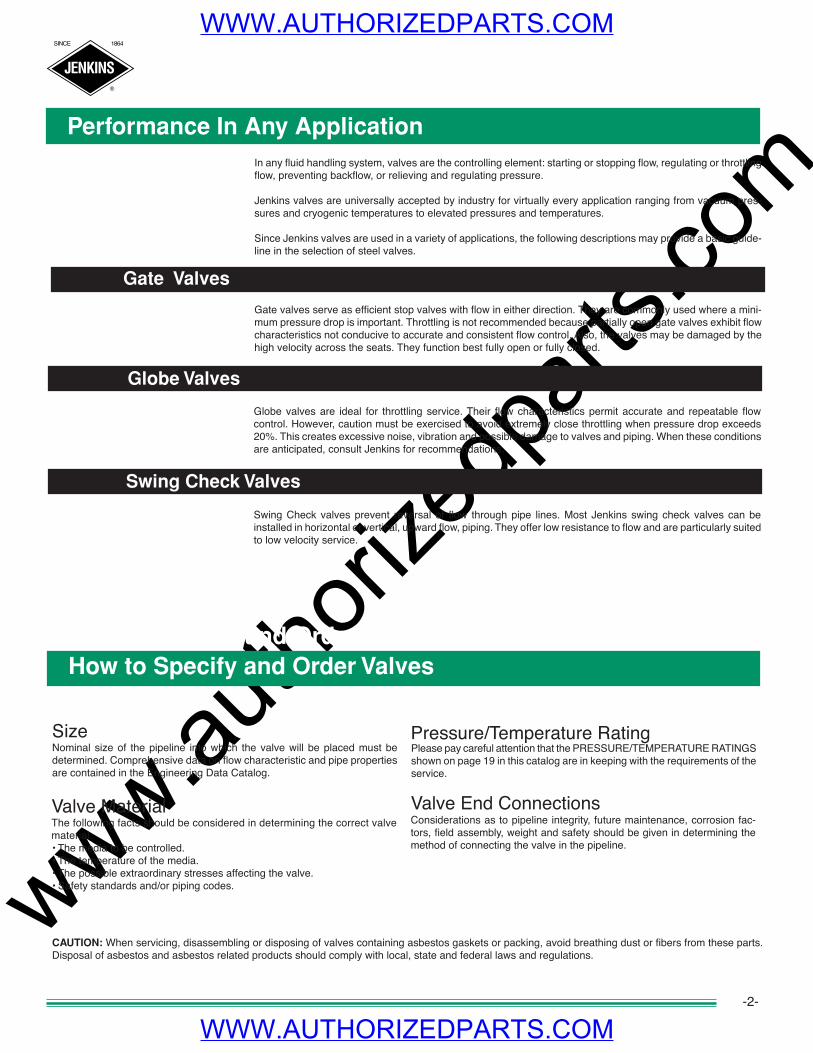
In any fluid handling system, valves are the controlling element: starting or stopping flow, regulating or throttlingflow, preventing backflow, or relieving and regulating pressure.
Jenkins valves are universally accepted by industry for virtually every application ranging from vacuum pres-sures and cryogenic temperatures to elevated pressures and temperatures.
Since Jenkins valves are used in a variety of applications, the following descriptions may provide a basic guide-line in the selection of steel valves.
Gate Valves
Globe Valves
Swing Check Valves
Performance In Any Application
Gate valves serve as efficient stop valves with flow in either direction. They are commonly used where a mini-mum pressure drop is important. Throttling is not recommended because partially open gate valves exhibit flowcharacteristics not conducive to accurate and consistent flow control. Also, the valves may be damaged by thehigh velocity across the seats. They function best fully open or fully closed.
Globe valves are ideal for throttling service. Their flow characteristics permit accurate and repeatable flowcontrol. However, caution must be exercised to avoid extremely close throttling when pressure drop exceeds20%. This creates excessive noise, vibration and possible damage to valves and piping. When these conditionsare anticipated, consult Jenkins for recommendations.
Swing Check valves prevent reversal of flow through pipe lines. Most Jenkins swing check valves can beinstalled in horizontal or vertical, upward flow, piping. They offer low resistance to flow and are particularly suitedto low velocity service.
How to Specify and Order Valves
WWW.AUTHORIZEDPARTS.COM
WWW.AUTHORIZEDPARTS.COM